agilent n9340b handheld spectrum analyzer€¦ · 2 n9340b user™s guide introduction the agilent...
TRANSCRIPT

Agilent N9340B Handheld Spectrum Analyzer
User�s Guide
!"
Notices© Agilent Technologies, Inc. 2008No part of this manual may be reproduced in any form or by any means (including electronic storage and retrieval or translation into a foreign language) without prior agreement and written consent from Agilent Technologies, Inc. as governed by United States and international copyright laws.
Manual Part NumberN9340-90008
EditionFirst edition, May 2008Printed in ChinaAgilent Technologies, Inc. Qianfeng Hi-Tech Industry Park Chengdu Hi-Tech Industrial Development Zone (West District)
WarrantyThe material contained in this document is provided �as is,� and is subject to being changed, without notice, in future editions. Further, to the maximum extent permitted by applicable law, Agilent disclaims all warranties, either express or implied, with regard to this manual and any information contained herein, including but not limited to the implied warranties of merchantability and fitness for a particular purpose. Agilent shall not be liable for errors or for incidental or consequential damages in connection with the furnishing, use, or performance of this document or of any information contained herein. Should Agilent and the user have a separate written agreement with warranty terms covering the material in this document that conflict with these terms, the warranty terms in the separate agreement shall control.
Technology Licenses The hardware and/or software described in this document are furnished under a license and may be used or copied only in accordance with the terms of such license.
Restricted Rights LegendIf software is for use in the performance of a U.S. Government prime contract or subcontract, Software is delivered and licensed as �Commercial computer software� as defined in DFAR 252.227-7014 (June 1995), or as a �commercial item� as defined in FAR 2.101(a) or as �Restricted computer software� as defined in FAR 52.227-19 (June 1987) or any equivalent agency regulation or contract clause. Use, duplication or disclosure of Software is subject to Agilent Technologies� standard commercial license terms, and non-DOD Departments and Agencies of the U.S. Government will receive no greater than Restricted Rights as defined in FAR 52.227-19(c)(1-2) (June 1987). U.S. Government users will receive no greater than Limited Rights as defined in FAR 52.227-14 (June 1987) or DFAR 252.227-7015 (b)(2) (November 1995), as applicable in any technical data.
Chengdu 611731, P.R.China
Software RevisionThis guide is valid for A.01.00 revisions of the Agilent N9340B Handheld Spectrum Analyzer firmware.
A CAUTION notice denotes a hazard. It calls attention to an operating proce-dure, practice, or the like that, if not correctly performed or adhered to, could result in damage to the product or loss of important data. Do not pro-ceed beyond a CAUTION notice until the indicated conditions are fully understood and met.
A WARNING notice denotes a hazard. It calls attention to an operating pro-cedure, practice, or the like that, if not correctly performed or adhered to, could result in personal injury or death. Do not proceed beyond a WARNING notice until the indicated conditions are fully understood and met.
CAUTION
WARNING
Table of Contents
1 OverviewIntroduction 2
Front Panel Overview 4
Top Panel Overview 5
Display Annotations 6
2 Getting StartedChecking Shipment and Order List 10
Power Requirements 11
AC Power Cords 12
Safety Considerations 13
Working with Batteries 16
Powering on the Analyzer for the First Time 18
Preparation for Use 19
Making a Basic Measurement 20
Contact Agilent Technologies 25
3 System SettingVisual and Audio Adjustment 28
System Setting 29
File 31
Show System 35
Show Error 36
Perform a Time Base Calibration 37
Factory Default Settings 38
4 Making MeasurementsMeasuring Multiple Signals 40
Measuring a Low-Level Signal 45
Improving Frequency Resolution and Accuracy 50
Making Distortion Measurements 51
Making a Stimulus Response Transmission Measurement 57
Measuring Stop Band Attenuation of a Low-pass Filter 59
Making a Reflection Calibration Measurement 61
Measuring Return Loss Using the Reflection Calibration Routine 64
Making an Anverage Power Measurement 65
Demodulate the AM and FM signals 70
5 Key ReferenceAmplitude 76
MODE 79
BW/SWP 88
Enter 94
ESC/CLR 95
Frequency 96
Marker 98
MEAS 103
SPAN 114
TRACE 115
LIMIT 120
6 SCPI Command ReferenceSCPI Language Basics 124
Common Commands 128
CALCulate Subsystem 131
DEMOdulation Subsystem 139
DISPlay Subsystem 140
INITiate Subsystem 142
INSTrument Subsystem 143
MEASure Subsystem 144
SENSe Subsystem 155
Status Subsystem 164
SYSTem Subsystem 174
TRACe Subsystem 175
Tracking Generator Subsystem 177
TRIGer Subsystem 180
UNIT Subsystem 182
7 Error MessagesError Message List 185
8 Menu MapAMPTD 190
BW/SWP 191
FREQ 192
MARKER 193
MEAS 194
MODE 195
SPAN 196
SYS 197
TRACE 198
Limit 199
Documentation Conventions:1. A pair of curly brackets { } indicates a softkey, for example {Start} refers to the Start softkey.2. A pair of square brackets [ ] indicates a hardkey, for example, [ENTER] refers to the ENTER hardkey.3. �Analyzer� refers to Agilent N9340B handheld spectrum analyzer in the following chapters.4. �DUT� refers to a device under test.
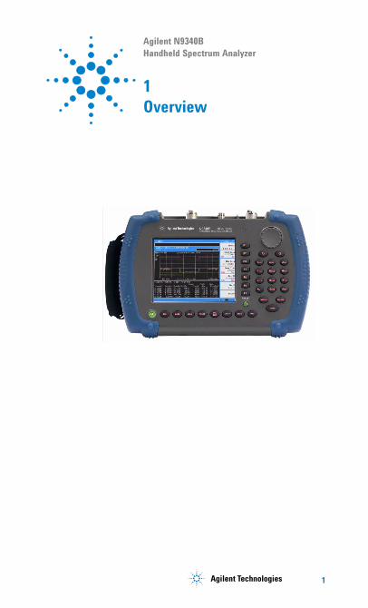
Agilent N9340B Handheld Spectrum Analyzer
1Overview
1!"
1 Overview
Introduction
The Agilent N9340B is a handheld spectrum analyzer with a frequency range is 100 kHz to 3 GHz, tunable to 9 kHz. It has several different measurement modes. Each mode offers a set of automatic measurements that pre- configure the analyzer settings for ease of use. It provides ultimate measurement flexibility in a package that is ruggedized for field environments and convenient for mobile applications.
Functionality and FeatureThe Agilent N9340B provides your with a comprehensive functionality set and measurement convenience, including:
� Power suite provides power measurement functionality on OBW (Occupied Bandwidth), channel power, ACPR (Adjacent Channel Power Ratio), SEM (Spectrum emission mask), field strength and spectrogram.
• Spectrum emission mask is a mask for out- of- channel emissions. it provide a user- defined channel setting and help user judge the signals.
� USB power sensor support supports Agilent U2000 series power sensors for high accuracy power measurement as a power meter.
� Demodulation analysis function provides optional AM/FM and ASK/FSK demodulation analysis function.
� Tracking generator provides an RF source for scalar network analysis (Option- TG3).
• High-sensitivity measurement includes a 3 GHz pre- amplifier (Option- PA3) enabling highly sensitivity measurements, useful in the analysis of low- level signals.
2 N9340B User�s Guide
Overview 1
Optimized UsabilityThe Agilent N9340B handheld spectrum analyzer provides enhanced usability:
• The 6.5-inch TFT colorful LCD screen ( pixels)
enables you to read the scans easily and clearly outdoors.
• Arc-shaped handle and rugged rubber casing ensure a comfortable and firm hold and ruggedness.
• SCPI remote control via USB and LAN port.
• The PC software is convenient for your futher editing and data analysis.
• 4-hour-time battery provides you a continuous work time in the field test.
• The light sensor adjusts the display brightness according to the environment to save power.
• The headphone jack on the top panel is for the audio signal analysis and monitor.
• Back-lit Keys makes you find the right keys in darkness easily.
640 480×
N9340B User�s Guide 3
1 Overview
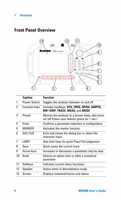
Front Panel Overview
N9340B HANDHELD SPECTRUM ANALYZER
100 kHz - 3.0 GHz
SYS M ODE M EAS TRACE BW/SWP AM PTD SPAN FREQ
ENTER
M ARKER ESC/ CLR
1ABC 2 DEF 3 GHI
4JKL 5M NO 6PQR
7STU 8VWX 9 YZ_
0SAVE LIMIT
PRESET
F1
F2
F3
F4
F5
F6
F7
13
1 2 3 4
56
7
8
9
101112
Caption Function1 Power Switch Toggles the analyzer between on and off2 Function keys Includes hardkeys: SYS, FREQ, SPAN, AMPTD,
BW/SWP, TRACE, MEAS, and MODE3 Preset Returns the analyzer to a known state, also turns
on/off Power save feature (press for 1 sec.)4 Enter Confirms a parameter selection or configuration5 MARKER Activates the marker function6 ESC/CLR Exits and closes the dialog box or clears the
character input7 LIMIT Sets limit lines for quick Pass/Fail judgement8 Save Quick saves the current trace9 Arrow keys Increases or decreases a parameter step by step10 Knob Selects an option item or edits a numerical
parameter11 Softkeys Indicates current menu functions12 Speaker Active when in demodulation mode13 Screen Displays measured traces and status
4 N9340B User�s Guide
Overview 1
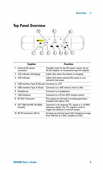
Top Panel Overview
PC
12-18 VDC 55W MAX
50 VDC MAX 33 dBm (2 W) MAX
RF INPUT 50 RF OUT 50 EXT TRIG IN/EXT REF IN
Ext. Power
Charging
1 2
9
3 4 5 7
810
6
Caption Function1 External DC power
connectorProvides input for the DC power source via an AC-DC adapter, or Automotive type DC adapter.
2 LED indicator (Charging) Lights (On) when the battery is charging3 LED indicator Lights (On) when external DC power is con-
nected to the tester4 USB interface Type B (Device) Connects to a PC5 USB interface Type A (Host) Connects to a USB memory stick or disk6 Headphone Connects to a headphone7 LAN Interface Connects to a PC for SCPI remote control8 RF OUT Connector The output for the built-in tracking generator.
Enabled with Option TG3.9 EXT TRIG IN/REF IN (BNC,
Female)Connects to an external TTL signal or a 10 MHz reference signal. The TTL signal is used to trigger the analyzer�s internal sweep
10 RF IN Connector (50 Ω) Accepts an external input with a frequency range from 100 kHz to 3 GHz, tunable to 9 kHz.
N9340B User�s Guide 5
1 Overview
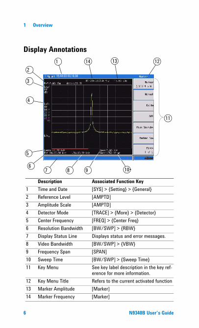
Display Annotations1
2
3
4
5
67 8 9 10
12
11
14 13
15:44:03 03,10,08
Description Associated Function Key1 Time and Date [SYS] > {Setting} > {General} 2 Reference Level [AMPTD] 3 Amplitude Scale [AMPTD] 4 Detector Mode [TRACE] > {More} > {Detector}5 Center Frequency [FREQ] > {Center Freq}6 Resolution Bandwidth [BW/SWP] > {RBW}7 Display Status Line Displays status and error messages.8 Video Bandwidth [BW/SWP] > {VBW}9 Frequency Span [SPAN]10 Sweep Time [BW/SWP] > {Sweep Time}11 Key Menu See key label description in the key ref-
erence for more information.12 Key Menu Title Refers to the current activated function13 Marker Amplitude [Marker]14 Marker Frequency [Marker]
6 N9340B User�s Guide

Overview 1
Instrument Markings
The CE mark shows that the product complies with all relevant European Legal Directives.
The CSA mark is a registered trademark of the Canadian Standards Association.
The C-Tick mark is a registered trademark of the Australian Spectrum Management Agency.
This symbol is an Industrial Scientific and Medical Group 1 Class A product (CISPR 11, Clause 4)
The ISM device complies with Canadian Interference- Causing Equipment Stan-dard- 001.
indicates that the user must refer to specific instructions in use.
The symbol is used to mark a position of the instrument power switch.
indicates this product complies with the WEEE Directive (2002/96/EC) marking requirements and you must not discard this equipment in domestic household waste. Do not dispose in domestic house-hold waste. To return unwanted prod-ucts, contact your local Agilent office, or refer to
http://www.agilent.com/environment/product/
N10149
ISM1-A
ICES/NMB-001
N9340B User�s Guide 7

1 Overview
8 N9340B User�s Guide
Agilent N9340B Handheld Spectrum Analyzer
2Getting Started
Information on checking the analyzer when received, preparation for use, basic instrument use, familiarity with controls, defining preset conditions, updating firmware, and contacting Agilent Technologies.
9 Agilent Technologies 9
2 Getting Started
Checking Shipment and Order List
Check the shipment and order list when you receive the shipment.
• Inspect the shipping container for damages. Signs of damage may include a dented or torn shipping container or cushioning material that indicate signs of unusual stress or compacting.
• Carefully remove the contents from the shipping container, and verify if the standard accessories and your ordered options are included in the shippment, according to the the checklist and “AC Power Cords" on page 12.
• For any question or problem, contact Agilent Technologies Customer Contact Center (CCC) for consultant and service. See “Contact Agilent Technologies" on page 25. For the latest service information please refer to: http://www.agilent.com/find/assist
10 N9340B User�s Guide
Getting Started 2
Power Requirements
The AC power supplied must meet the following requirements:
The AC/DC power supply charger adapter supplied with the analyzer is equipped with a three- wire power cord, in accordance with international safety standards. This power cord grounds the analyzer cabinet when it is connected to an appropriate power line outlet. The power cord appropriate to the original shipping location is included with the analyzer.
Various AC power cables are available from Agilent that are unique to specific geographic areas. You can order additional AC power cords are correct for use in different areas. The AC Power Cords table provides a lists of the available AC power cords, the plug configurations, and identifies the geographic area in which each cable is typically used.
The detachable power cord is the product disconnecting device. It disconnects the main AC circuits from the DC supply before other parts of the product. The front- panel switch is only a standby switch and do not disconnect instrument from AC LINE power.
Voltage: 100 VAC to 240 VAC
Frequency: 50 to 60 Hz
Power: Maximum 62 W
N9340B User�s Guide 11
2 Getting Started
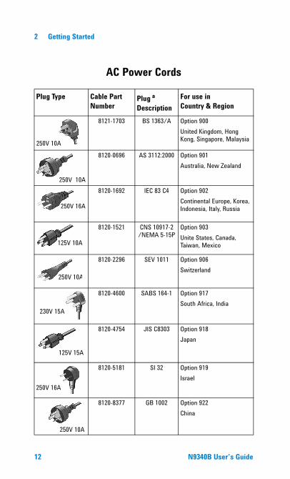
Plug Type Cable Part Number
Plug a
DescriptionFor use in Country & Region
250V 10A
8121-1703 BS 1363/A Option 900United Kingdom, Hong Kong, Singapore, Malaysia
8120-0696 AS 3112:2000 Option 901Australia, New Zealand
250V 16A
8120-1692 IEC 83 C4 Option 902Continental Europe, Korea, Indonesia, Italy, Russia
125V 10A
8120-1521 CNS 10917-2/NEMA 5-15P
Option 903Unite States, Canada, Taiwan, Mexico
250V 10A
8120-2296 SEV 1011 Option 906Switzerland
230V 15A
8120-4600 SABS 164-1 Option 917South Africa, India
8120-4754 JIS C8303 Option 918Japan
250V 16A
8120-5181 SI 32 Option 919Israel
8120-8377 GB 1002 Option 922China
AC Power Cords
250V 10A
250V 10A
125V 15A
12 N9340B User�s Guide

Getting Started 2
Safety Considerations
Agilent has designed and tested the N9340B handheld spectrum analyzer for Measurement, Control and Laboratory Use in accordance with Safety Requirements IEC 61010- 1: 2001, UL 61010- 1 (2004), and CSA C22.2 No.61010- 1- 04. The tester is supplied in a safe condition. The N9340B is also designed for use in Installation Category II and Pollution Degree 2 per IEC 61010 and IEC 60664 respectively.
Read the following safety notices carefully before you start to use a N9340B handheld spectrum analyzer to ensure safe operation and to maintain the product in a safe condition.
WARNING Personal injury may result if the analyzer�s cover is removed. There are no operator-serviceable parts inside. Always contact Agilent qualified personnel for service. Disconnect the product from all voltage sources while it is being opened.
WARNING This product is a Safety Class I analyzer. The main plug should be inserted in a power socket outlet only if provided with a protective earth contact. Any interruption of the protective conductor inside or outside of the product is likely to make the product dangerous. Intentional interruption is prohibited.
WARNING Electrical shock may result when cleaning the analyzer with the power supply connected. Do not attempt to clean internally. Use a dry soft cloth to clean the outside case only.
WARNING Always use the three-pin AC power cord supplied with this product. Failure to ensure adequate earth grounding by not using this cord may cause personal injury and product damage.
N9340B User�s Guide 13
2 Getting Started
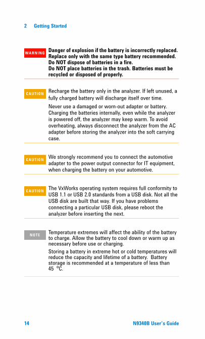
WARNING Danger of explosion if the battery is incorrectly replaced. Replace only with the same type battery recommended. Do NOT dispose of batteries in a fire. Do NOT place batteries in the trash. Batteries must be recycled or disposed of properly.
CAU-CAUTION Recharge the battery only in the analyzer. If left unused, a fully charged battery will discharge itself over time.Never use a damaged or worn-out adapter or battery. Charging the batteries internally, even while the analyzer is powered off, the analyzer may keep warm. To avoid overheating, always disconnect the analyzer from the AC adapter before storing the analyzer into the soft carrying case.
CAU-CAUTION We strongly recommend you to connect the automotive adapter to the power output connector for IT equipment, when charging the battery on your automotive.
CAU-CAUTION The VxWorks operating system requires full conformity to USB 1.1 or USB 2.0 standards from a USB disk. Not all the USB disk are built that way. If you have problems connecting a particular USB disk, please reboot the analyzer before inserting the next.
NOTE Temperature extremes will affect the ability of the battery to charge. Allow the battery to cool down or warm up as necessary before use or charging.Storing a battery in extreme hot or cold temperatures will reduce the capacity and lifetime of a battery. Battery storage is recommended at a temperature of less than 45 oC.
14 N9340B User�s Guide
Getting Started 2
Environmental RequirementsThe N9340B is designed for use under the following conditions:
• Operating temperature:
–10 C to +50 C (with battery)
0 C to +40 C (with adapter)
• Storage temperature: –40 C to +70 C
• Humidity: 95% or less
• Altitude: 9200 m
Electrical RequirementsThe analyzer allows the use of either a lithium battery pack (internal), AC- DC adapter shipped with the analyzer, or optional automotive +12 VDC adapter for its power supply.
Electrostatic Discharge (ESD) PrecautionsThis analyzer was constructed in an ESD protected environment. This is because most of the semiconductor devices used in this analyzer are susceptible to damage by static discharge.
Depending on the magnitude of the charge, device substrates can be punctured of destroyed by contact or proximity of a static charge. The result can cause degradation of device performance, early failure, or immediate destruction.
These charges are generated in numerous ways, such as simple contact, separation of materials, and normal motions of persons working with static sensitive devices.
When handling or servicing equipment containing static sensitive devices, adequate precautions must be taken to prevent device damage or destruction. Only those who are thoroughly familiar with industry accepted techniques for handling static sensitive devices should attempt to service circuitry with these devices.
° °° °
° °
N9340B User�s Guide 15
2 Getting Started
Working with Batteries
Always use the original battery type, as supplied with the analyzer.
Installing a Battery
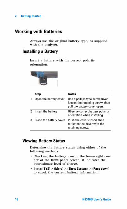
Insert a battery with the correct polarity orientation.
Viewing Battery StatusDetermine the battery status using either of the following methods:
• Checking the battery icon in the lower- right cor-ner of the front- panel screen: it indicates the approximate level of charge.
• Press [SYS] > {More} > {Show System} > {Page down} to check the current battery information.
Step Notes1 Open the battery cover Use a phillips type screwdriver,
loosen the retaining screw, then pull the battery cover open.
2 Insert the battery Observe correct battery polarity orientation when installing.
3 Close the battery cover Push the cover closed, then re-fasten the cover with the retaining screw.
16 N9340B User�s Guide
Getting Started 2
Charging a BatteryThis typically takes about three hours.
1 Insert the battery in the analyzer.
2 Attach the AC- DC adapter and switch on the external power.
3 The charge indicator lights, indicating that the battery is charging. When the battery is fully charged, the green charging indicator turns off.
During charging and discharging, the battery voltage, current, and temperature are monitored. If any of the monitored conditions exceed their safety limits, the battery will terminate any further charging or discharging until the error condition is corrected.
NOTE Only charge the battery when it is installed in the analyzer. Full charge the battery before first using the analyzer.
N9340B User�s Guide 17
2 Getting Started
Powering on the Analyzer for the First Time
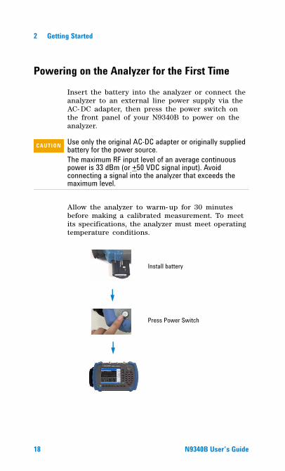
Insert the battery into the analyzer or connect the analyzer to an external line power supply via the AC- DC adapter, then press the power switch on the front panel of your N9340B to power on the analyzer.
Allow the analyzer to warm- up for 30 minutes before making a calibrated measurement. To meet its specifications, the analyzer must meet operating temperature conditions.
CAU-CAUTION Use only the original AC-DC adapter or originally supplied battery for the power source.The maximum RF input level of an average continuous power is 33 dBm (or +50 VDC signal input). Avoid connecting a signal into the analyzer that exceeds the maximum level.
Install battery
Press Power Switch
18 N9340B User�s Guide
Getting Started 2
Preparation for Use
Use [SYS] hardkey to check or set the system settings of your analyzer.
Setting up your N9340B1 Press [SYS] > {Setting} > {General} to set time and
power saving mode:� Press {Time/Date} to set the time and date.
� Press {Power Manager} to select a time for the follow three modes:
2 Press [SYS] > {Setting} > {Language} to select a language displayed on screen.
3 Press [SYS] > {Brightness} and then rotate the knob to adjust display brightness.
4 Press [SYS] > {Key Beep} to toggle the buzzer beep function between on and off.
Checking Instrument Information1 Press [SYS] > {More} > {Show System} to display the
system information.
2 Press [SYS] > {More} > {Option} to display the option information.
3 Press [SYS] > {More} > {Show Error} to display the error information.
Testing buttons Press [SYS] > {More} > {Diagnostics} > {Front Panel} to test all the front panel keys except [PRESET] and power switch.
• turn off backlight• turn off screen display• turn off both backlight and screen display
N9340B User�s Guide 19
2 Getting Started
Making a Basic Measurement
This section provides information on basic analyzer operations. It assumes that you are familiar with the front and top panel buttons and keys, and display annotations of your analyzer. If you are not, please refer to “Front Panel Overview" on page 4, and “Top Panel Overview" on page 5, and “Display Annotations" on page 6.
For more details on making measurements, please refer to “Making Measurements" on page 39”.
Entering DataWhen setting measurement parameters, there are several ways to enter or modify active function values:
1 Using the Front Panel Knob
Increases or decreases the current value.
2 Using the Arrow Keys
Increases or decreases the current value by the step unit defined.
Press [FREQ] > {CF Step} to set the frequency by an auto- coupled step (Step = Span/10, when {CF Step} mode is set to Auto).
3 Using the Numeric Keypad
Enters a specific value. Then press a terminator key (either a specified unit softkey or [ENTER]) to confirm input.
4 Using the Unit Softkeys
Terminates a parameter value which requires a unit input.
5 Using the Enter Key
Terminates an entry or confirms a selection.
20 N9340B User�s Guide
Getting Started 2
Viewing a Signal on the Analyzer1 Use a signal generator to generate a CW signal
of 1.0 GHz, at a power level of 0.0 dBm.
2 Press [SYS] > {Setting} > {PwrOn/Preset} > {Preset Type} and select Default to toggle the preset setting to factory- defined status.
3 Press the green [Preset] key to restore the analyzer to its factory- defined setting.
4 Connect the generator’s RF OUT connector to analyzer’s RF IN connector.
5 Press [FREQ] > 1 > {GHz} to set the analyzer center frequency to 1 GHz.
6 Press [SPAN] > 5 > {MHz} to set the analyzer frequency span to 5 MHz.
7 Press [MARKER] > {Peak Search} to place a marker (M1) at the highest peak (1 GHz) on the display.
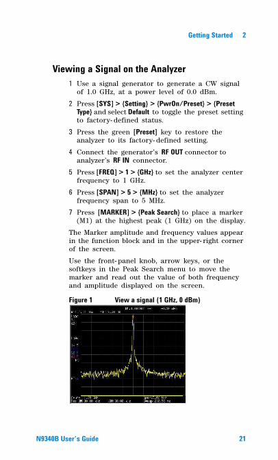
The Marker amplitude and frequency values appear in the function block and in the upper- right corner of the screen.
Use the front- panel knob, arrow keys, or the softkeys in the Peak Search menu to move the marker and read out the value of both frequency and amplitude displayed on the screen.
Figure 1 View a signal (1 GHz, 0 dBm)
N9340B User�s Guide 21
2 Getting Started
Some Helpful Tips
Performing a time-base calibrationThe N9340B provides a manual calibration function to calibrate the time base. The analyzer should warm up for approximately 30 minutes before calibration. Use a BNC cable to connect a 10 MHz reference signal to the EXT TRIG IN connector of the N9340B, then press [SYS] > {More} > {Calibration} > {Time Base} to initiate a calibration.
Selecting a preset typePress [SYS] > {Setting} > {PwrOn/Preset} > {Preset Type} to choose the preset types. The analyzer has three types of preset setting for you to choose from:
� DefaultRestores the analyzer to its factory- defined set-ting. The factory default settings can be found, “Factory Default Settings" on page 38.
� UserRestores the analyzer to a user- defined setting. See “Saving a User- defined Preset" on page 22.
� LastRestores the analyzer to the last time setting.
Saving a User-defined PresetIf you frequently use system settings that are not the factory defaults, refer to the following steps to create a user- defined system settings that can be easily recalled at the power up state:
1 Set analyzer parameters by the knob, the arrow keys or the numeric keypad.
2 Press [SYS] > {Setting} > {PwrOn/Preset} > {Save User} to save the current parameters as the user preset setting.
22 N9340B User�s Guide
Getting Started 2
3 Press [SYS] > {Setting} > {PwrOn/Preset} > {Preset Type User} to set the preset mode to user defined system setting.
4 Press [Preset], the instrument will be set to the state you previously saved.
Saving Multiple Test SetupsTest Setups that are unique and are neccessary to recall frequently can be saved as an instrument state file. Other file types are described on “File Types" on page 31.
Upgrading Firmware
The N9340B allows firmware updating quickly and easily. Perform the following steps for updating the firmware in your instrument:
1 Set up a folder named “N9340DATA” in the root directory of a USB memory stick, that is to be used for transferring the firmware to the instrument.
2 Store the firmware update application into the folder named N9340DATA on the memory stick.
3 Insert the USB memory stick into the correct USB connector on the top panel of the analyzer.
4 Press [SYS] > {More} > {Upgrade} > {Firmware} to activate the firmware updating procedure. The analyzer will perform the update automatically.
CAU-CAUTION When updating firmware, there must be a constant power supply to for at least 10 minutes. If power fails during the updating process it can cause damage to the instrument.
N9340B User�s Guide 23
2 Getting Started
Adding an OptionPressing [SYS] > {More} > {Option} > {Add Option} brings up a dialog box for entering the option license code. Use the numeric keypad to input the option license code and then use the [ENTER] key as a terminator. If the analyzer recognizes the option license code, a message “Option activated successfully” will appear in the status line. If the code is not recognized , a message “Invalid option licence” will appear in the status line.
24 N9340B User�s Guide
Getting Started 2
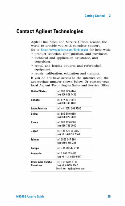
Contact Agilent TechnologiesAgilent has Sales and Service Offices around the world to provide you with complete support. Go to http://www.agilent.com/find/assist for help with:• product selection, configuration, and purchases. • technical and application assistance, and
consulting. • rental and leasing options, and refurbished
equipment.• repair, calibration, education and training.If you do not have access to the internet, call the appropriate number shown below. Or contact your local Agilent Technologies Sales and Service Office.
United States (tel) 800 829 4444(fax) 800 829 4433
Canada (tel) 877 894 4414(fax) 800 746 4866
Latin America (tel) +1 (305) 269 7500
China (tel) 800 810 0189(fax) 800 820 2816
Korea (tel) 080 769 0800(fax) 080 769 0900
Japan (tel) +81 426 56 7832(fax) +81 426 56 7840
Taiwan (tel) 0800 047 866(fax) 0800 286 331
Europe (tel) +31 20 547 2111
Australia (tel) 1 800 629 485(fax) +61 (3) 9210 5947
Other Asia Pacific Countries
(tel) +65 6375 8100(fax) +65 6755 0042Email: [email protected]
N9340B User�s Guide 25

2 Getting Started
26 N9340B User�s Guide
Agilent N9340B Handheld Spectrum Analyzer
3System Setting
Information on System Settings, File types, Saving a file, Quick save a Trace/Screen, Instrument Default Settings.
27Agilent Technologies
3 System Setting
Visual and Audio Adjustment
Display AdjustmentPress [SYS] > {Brightness} to toggles the screen brightness between Auto and Man. When it sets to Auto, the brightness will adjust according to the environment automatically with the built- in light sensor. When it sets to Man, it’s available for you to set a fixed brightness value manually.
Setting button backlightPress [SYS] > {KeyBackLight} > {BackLight} to toggles the button backlight on and off.
Setting Key BeepPress [SYS] > {Key Beep} to activate the key beep function as an indicator of key operation.
28 N9340B User�s Guide
System Setting 3
System SettingIncludes general system settings, displayed language setting, and external input setting.
General system settingsProvides the following system setting options:
Time/DatePress [SYS] > {Setting} > {General} > {Time/Date} to set the date and time of the analyzer.
The analyzer requires you to input the time in a HHMMSS format, and the date in a YYYYMMDD format.
Power ManagerPress [SYS] > {Setting} > {General} > {Power manager} to select a power saving mode from the followings. The three modes provide a choice for setting the idle time limit as 5, 15, 30 minutes or 4 hours.
� Backlight The analyzer turns off the backlight of the LCD screen after a pre- defined idle time. Press any key to re- activate the backlight after the backlight power- saving mode has been triggered.
� LCD The analyzer turns off the LCD display after a pre- defined idle time. Press any key to re- activate the LCD display after the LCD display power- saving mode has been triggered.
� All - Backlight & LCD The analyzer turns off the both the LCD display and the backlight after a pre- defined idle time. Press any key to re- activate the backlight and LCD display after the backlight and LCD power- saving mode has been triggered.
N9340B User�s Guide 29
3 System Setting
Ext Input
Toggles the channel for external input between Ref and Trig. Ref refers to a 10 MHz reference signal; Trig refers to a TTL signal.
Key Access: [SYS] > {Setting} > {Ext Input}
External Reference (Ref)Use the external reference function as follows:
1 Input a 10 MHz signal to the EXT TRIG IN/REF IN connector.
2 Press [SYS] > {Setting} > {Ext Input Ref} to enable the external reference signal input.
The analyzer then turns off its internal reference.
External Trigger (Trig)When an external TTL signal is used for triggering function, the analyzer uses the inner reference as default.
Use the external trigger function as follows:
1 Press [SYS] > {Setting} > {Ext Input Trig} to enable the external TTL signal input.
2 Press [SPAN] > {Zero Span} to activate the Trigger function.
3 Access the associated softkeys to select the rising edge (Ext Rise) or the falling edge (Ext Fall) as the trigger threshold.
NOTE The external Ref and Trig functions are not available at the same time.
NOTE The trace will halt in external trigger mode till the trigger threshold is met or the free run function is activated.
30 N9340B User�s Guide
System Setting 3
FilePressing [SYS] > {File} accesses to the menu that allows you to manage the file saving and loading.
File TypesEach file type has a specific purpose as defined below. Pressing [SYS] > {File} > {File Setup} > {File type} allows the user to select a file type from one of the following:
• Trace (*.DAT) A trace file records trace data and controls.
• Screen (*.JPG) A screen file records graphic information of the current screen.
• State (*.STA) A state file records the current controls and settings of the analyzer. Use this file type for saving test parameters for future recall, such as Frequency, Amplitude and BW settings.
• Pattern (*.PTN) A pattern file records the limit line settings.
• Spectrum Mask (*.MSK) A mask file records the spectrum mask settings. You can use the N9340 PC software to edit a mask file and transfer the mask to your N9340B.
• CSV (*.CSV) A CSV file records the trace data and available for review on PC.
• Setup (*.SET) A setup file records the system setting information, such as language, date/time, and power saving mode. This file type is not used for test parameter setup information.
NOTE A USB memory stick of FAT32 or FAT16 format and with only one memory zone is primarily required when using USB memory stick for file saving and loading.
N9340B User�s Guide 31
3 System Setting
Saving PathPress [SYS] > {File} > {File Setup} > {Save Path} to select a path from one of the following:
• Local memory
• External USB memory stick
Saving a file
Refer to the following three steps to save a file:
1 Press [SYS] > {File} > {File Setup} to select the save path and file type.
2 Edit a file name. A file name can consist of letters and digits. A single key stroke on the numerical keypad inputs a digital number; and consecutive key stroke selects and inputs a letter.
3 Press {Save} to save the file.
When a file saving completes, the message “File Saved” displays on the bottom line of the screen.
Quick saving a trace or a screenPress [0/Save] to quickly save a trace or a screen to either the local memory or an external USB device, depending upon the setup of the save path.
NOTE When selecting a file type, you can edit a file name by pressing the numeric and alphabetic hardkeys on the right side of the analyzer�s front panel.
NOTE When the saving path to USB, files are automatically saved into a folder named as N9340DATA in the root directory of the USB memory stick. If the USB memory stick connection can not be updated, remove the USB memory stick, then cycle the power and re-insert the USB memory stick.
32 N9340B User�s Guide
System Setting 3
Three steps for saving a trace or a screen:
1 Press [SYS] > {File} > {File Setup} > {Shortcut Type} to indicate the shortcut type to either a trace or a screen copy.
2 Press [SYS] > {File} > {File Setup} > {Save Path} to either local memory or an external USB device.
3 Press [Return], [Save] to save a trace or a screen copy to the pre- defined memory. The trace or screen will be automatically assigned with a default file name. A trace will be assigned with a file name, such as HYTRACE, HYTRACE_1, and consecutive decimal numbers appended to the alphabetic file name, such as HYSCREEN, HYSCREEN_1 and consecutive decimal numbers appended to the alphabetic file name.
Quick saving a setupPress [SYS] > {More} >{More} > {SaveSYS Setup} to quick save the current system settings. This does not include the test parameters, such as, Frequency, BW, and Amplitude settings.
Quick recalling a setup� Load defaultPress [SYS] > {More} > {More} > {Re-SYS Setup} > {Load default} to recall the factory default setup.
� User SetupPress [SYS] > {More} > {More} > {Re-SYS Setup} > {User Setup} to recall a customized setup that has been saved previously.
NOTE All the quick saving utility of system state is equal to the saving utility under the [SYS] > {File}.
N9340B User�s Guide 33
3 System Setting
Viewing file listRefer to the following two steps to view file list:
1 Select the directory to view. Press [SYS] > {File} > {View} to toggle the displayed file list from local memory or an external USB memory stick.
2 Select the file type you wish to view. Press [SYS] > {File} > {File setup} > {File type} to select a file type.
Deleting a file
1 Press [SYS] > {File} > {View} to select a directory.
2 Press [SYS] > {File} > {File setup} > {File type} to select a file type.
3 Rotate the knob to highlight a file.
4 Press {Delete} to delete a selected file. The file will be deleted after you press Yes to confirm deleting.
Loading a file
1 Press [SYS] > {File} > {View} to select a directory.
2 Press {File Setup} > {File type} to select a file type.
3 Rotate the knob to highlight a file.
4 Press {Load Now} to recall the pre- saved file.
CAU-CAUTIONBE
Once a file is deleted, it CANNOT be recovered. Care-fully decide whether to delete a file before proceeding.
NOTE A screen file (*.JPG) can not be loaded into the analyzer.
34 N9340B User�s Guide
System Setting 3
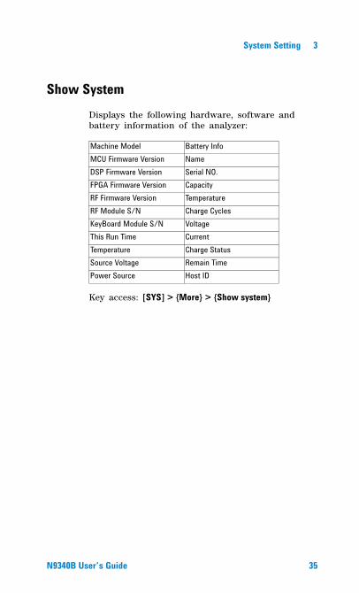
Show SystemDisplays the following hardware, software and battery information of the analyzer:
Key access: [SYS] > {More} > {Show system}
Machine Model Battery InfoMCU Firmware Version NameDSP Firmware Version Serial NO.FPGA Firmware Version CapacityRF Firmware Version TemperatureRF Module S/N Charge CyclesKeyBoard Module S/N VoltageThis Run Time CurrentTemperature Charge StatusSource Voltage Remain TimePower Source Host ID
N9340B User�s Guide 35
3 System Setting
Show ErrorAccesses a list of the 30 most recent error messages reported by the analyzer. The most recent error will appear at the bottom of the list. If the error list is longer than 30 entries, the analyzer reports an error message [�350, Query overflow]. When in remote control, and the error list is greater than 30 entries, the error display is halted and a message at the bottom of the list informs the user that error exceed 30.
Key access: [SYS] > {More} > {Show Error}For more information, refer to “Error Messages" on page 183.
36 N9340B User�s Guide
System Setting 3
Perform a Time Base CalibrationWhen the calibration function is triggered, the current measurement is interrupted and a gauge displays on the LCD. The gauge simply indicates calibration action rather than calibration course, as the calibration time is unpredictable. When the calibration is finished, the LCD displays a calibration, and the interrupted measurement restarts.
Key Access: [SYS] > {More} > {Calibration}
NOTE Time base calibration takes during a short time only when the inner temperature is stable. When the inner temperature is increasing, calibration takes a long-time course or will fail. If the input reference signal is abnormal, the calibration cycle will take a long and unpredictable time to exit, and the LCD displays an error message.
N9340B User�s Guide 37
3 System Setting
Factory Default Settings
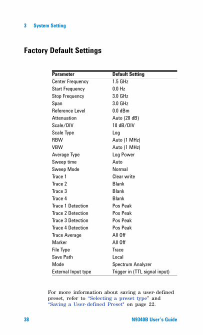
For more information about saving a user- defined preset, refer to “Selecting a preset type” and “Saving a User- defined Preset" on page 22.
Parameter Default SettingCenter Frequency 1.5 GHzStart Frequency 0.0 HzStop Frequency 3.0 GHzSpan 3.0 GHzReference Level 0.0 dBmAttenuation Auto (20 dB)Scale/DIV 10 dB/DIVScale Type LogRBW Auto (1 MHz)VBW Auto (1 MHz)Average Type Log PowerSweep time Auto Sweep Mode NormalTrace 1 Clear writeTrace 2 BlankTrace 3 BlankTrace 4 BlankTrace 1 Detection Pos PeakTrace 2 Detection Pos PeakTrace 3 Detection Pos PeakTrace 4 Detection Pos PeakTrace Average All OffMarker All OffFile Type TraceSave Path LocalMode Spectrum AnalyzerExternal Input type Trigger in (TTL signal input)
38 N9340B User�s Guide

Agilent N9340B Handheld Spectrum Analyzer
4Making Measurements
39!"
4 Making Measurements
Measuring Multiple Signals
This section provides information on measuring multiple signals.
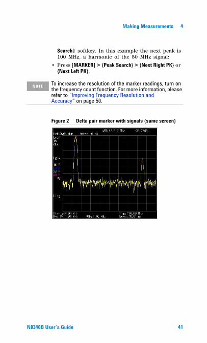
Comparing Signals on the Same Screen The N9340B can easily compare frequency and amplitude signal differences. For example, measuring radio or television signal spectra. The Delta Marker function allows two signals to be compared when both appear on the screen at the same time. In this following example, a 50 MHz input signal is used to measure frequency and amplitude differences between two signals on the same screen. The Delta Marker function is demonstrated in this example.
1 Press [PRESET] to set the analyzer to a factory default setting.
2 Input a signal (0 dB, 50 MHz) to the RF IN con-nector of the analyzer.
3 Set the analyzer start frequency, stop frequency and reference level to view the 50 MHz signal and its harmonics up to 100 MHz:
� Press [FREQ] > 40 > {MHz}� Press [FREQ] > 110 > {MHz}� Press [AMPTD] > 0 > {dBm}
4 Press [MARKER] > {Peak search} to place a marker on the highest peak on the display (50 MHz). The {Next Left PK} and {Next Right PK} softkeys are available to move the marker from peak to peak.
5 Press [MARKER] > {Delta} to anchor the first marker (labeled as M1) and activate a delta marker.
The label on the first marker now reads 1R, indicating that it is the reference point.
6 Move the second marker to another signal peak using the front panel knob or by using the {Peak
40 N9340B User�s Guide
Making Measurements 4
Search} softkey. In this example the next peak is 100 MHz, a harmonic of the 50 MHz signal:
• Press [MARKER] > {Peak Search} > {Next Right PK} or {Next Left PK}.
Figure 2 Delta pair marker with signals (same screen)
NOTE To increase the resolution of the marker readings, turn on the frequency count function. For more information, please refer to �Improving Frequency Resolution and Accuracy" on page 50.
N9340B User�s Guide 41
4 Making Measurements
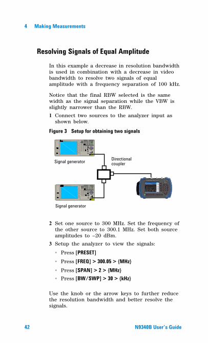
Resolving Signals of Equal Amplitude
In this example a decrease in resolution bandwidth is used in combination with a decrease in video bandwidth to resolve two signals of equal amplitude with a frequency separation of 100 kHz.
Notice that the final RBW selected is the same width as the signal separation while the VBW is slightly narrower than the RBW.
1 Connect two sources to the analyzer input as shown below.
Figure 3Frequency
Ent er
7 M ODOn/ Off
RF
4
1
0
2
9
6
3
On/ Off
Amplit ude FM
Utility
LF Out
Preset
Local
AM I/Q
File
TriggerPulseM
·
Sw eep
8
5
Remot e
StandbyOn
N9310A RF Signal Generator 9 kHz - 3.0 GHz
REVERSE PW R4W M AX 30VDC
LF OUT RF OUT 50
FUNCTIONS
Frequency
Enter
7 M ODOn/ Off
RF
4
1
0
2
9
6
3
On/ Off
Amplitude FM
Ut ili ty
LF Out
Preset
Local
AM I/ Q
File
TriggerPulseM
·
Sw eep
8
5
Remote
StandbyOn
N9310A RF Signal Generator 9 kHz - 3.0 GHz
REVERSE PWR4W MAX 30VDC
LF OUT RF OUT 50
FUN CTIONS
Directional couplerSignal generator
Signal generator
Setup for obtaining two signals
2 Set one source to 300 MHz. Set the frequency of the other source to 300.1 MHz. Set both source amplitudes to –20 dBm.
3 Setup the analyzer to view the signals:
� Press [PRESET]� Press [FREQ] > 300.05 > {MHz}� Press [SPAN] > 2 > {MHz}� Press [BW/SWP] > 30 > {kHz}
Use the knob or the arrow keys to further reduce the resolution bandwidth and better resolve the signals.
42 N9340B User�s Guide
Making Measurements 4
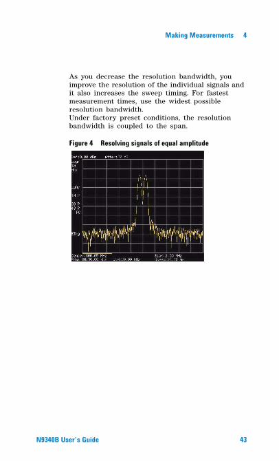
As you decrease the resolution bandwidth, you improve the resolution of the individual signals and it also increases the sweep timing. For fastest measurement times, use the widest possible resolution bandwidth. Under factory preset conditions, the resolution bandwidth is coupled to the span.
Figure 4 Resolving signals of equal amplitude
N9340B User�s Guide 43
4 Making Measurements
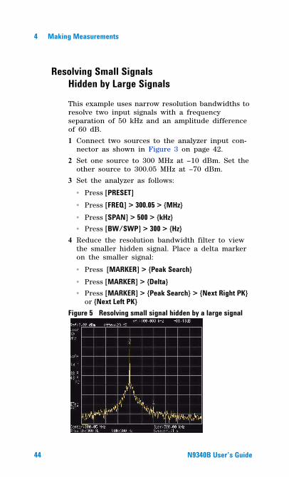
Resolving Small Signals Hidden by Large Signals
This example uses narrow resolution bandwidths to resolve two input signals with a frequency separation of 50 kHz and an amplitude differenceof 60 dB.
1 Connect two sources to the analyzer input con-nector as shown in Figure 3 on page 42.
2 Set one source to 300 MHz at –10 dBm. Set the other source to 300.05 MHz at –70 dBm.
3 Set the analyzer as follows:
� Press [PRESET]� Press [FREQ] > 300.05 > {MHz}� Press [SPAN] > 500 > {kHz}� Press [BW/SWP] > 300 > {Hz}
4 Reduce the resolution bandwidth filter to view the smaller hidden signal. Place a delta marker on the smaller signal:
� Press [MARKER] > {Peak Search}� Press [MARKER] > {Delta}� Press [MARKER] > {Peak Search} > {Next Right PK}
or {Next Left PK}Figure 5 Resolving small signal hidden by a large signal
44 N9340B User�s Guide
Making Measurements 4
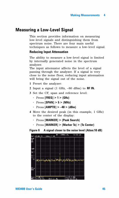
Measuring a Low-Level SignalThis section provides information on measuring low- level signals and distinguishing them from spectrum noise. There are four main useful techniques as follows to measure a low- level signal.
Reducing Input AttenuationThe ability to measure a low- level signal is limited by internally generated noise in the spectrum analyzer.The input attenuator affects the level of a signal passing through the analyzer. If a signal is very close to the noise floor, reducing input attenuation will bring the signal out of the noise.
1 Preset the analyzer:
2 Input a signal (1 GHz, –80 dBm) to RF IN. 3 Set the CF, span and reference level:
� Press [FREQ] > 1 > {GHz}� Press [SPAN] > 5 > {MHz}� Press [AMPTD] > �40 > {dBm}
4 Move the desired peak (in this example, 1 GHz) to the center of the display:
� Press [MARKER] > {Peak Search}� Press [MARKER] > {Marker To} > {To Center}
Figure 6 A signal closer to the noise level (Atten:10 dB)
N9340B User�s Guide 45
4 Making Measurements
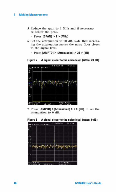
5 Reduce the span to 1 MHz and if necessary re- center the peak.
� Press [SPAN] > 1 > {MHz}6 Set the attenuation to 20 dB. Note that increas-
ing the attenuation moves the noise floor closer to the signal level.
� Press [AMPTD] > {Attenuation} > 20 > {dB}
Figure 7 A signal closer to the noise level (Atten: 20 dB)
7 Press [AMPTD] >{Attenuation} > 0 > {dB} to set the attenuation to 0 dB.
Figure 8 A signal closer to the noise level (Atten: 0 dB)
46 N9340B User�s Guide
Making Measurements 4
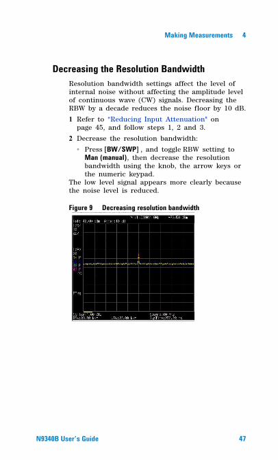
Decreasing the Resolution BandwidthResolution bandwidth settings affect the level of internal noise without affecting the amplitude level of continuous wave (CW) signals. Decreasing the RBW by a decade reduces the noise floor by 10 dB.
1 Refer to “Reducing Input Attenuation" on page 45, and follow steps 1, 2 and 3.
2 Decrease the resolution bandwidth:
� Press [BW/SWP] , and toggle RBW setting to Man (manual), then decrease the resolution bandwidth using the knob, the arrow keys or the numeric keypad.
The low level signal appears more clearly because the noise level is reduced.
Figure 9 Decreasing resolution bandwidth
N9340B User�s Guide 47
4 Making Measurements
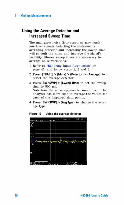
Using the Average Detector and Increased Sweep TimeThe analyzer’s noise floor response may mask low- level signals. Selecting the instruments averaging detector and increasing the sweep time will smooth the noise and improve the signal’s visibility. Slower sweep times are necessary to average noise variations.
1 Refer to “Reducing Input Attenuation" on page 45, and follow steps 1, 2 and 3.
2 Press [TRACE] > {More} > {Detector} > {Average} to select the average detector.
3 Press [BW/SWP] > {Sweep Time} to set the sweep time to 500 ms. Note how the noise appears to smooth out. The analyzer has more time to average the values for each of the displayed data points.
4 Press [BW/SWP] > {Avg Type} to change the aver-age type.
Figure 10 Using the average detector
48 N9340B User�s Guide
Making Measurements 4
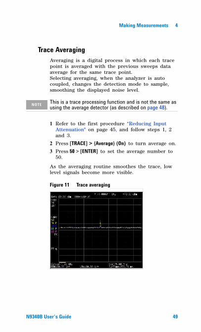
Trace AveragingAveraging is a digital process in which each trace point is averaged with the previous sweeps data average for the same trace point.Selecting averaging, when the analyzer is auto coupled, changes the detection mode to sample, smoothing the displayed noise level.
1 Refer to the first procedure “Reducing Input Attenuation" on page 45, and follow steps 1, 2 and 3.
2 Press [TRACE] > {Average} (On) to turn average on.
3 Press 50 > [ENTER] to set the average number to 50.
As the averaging routine smoothes the trace, low level signals become more visible.
Figure 11 Trace averaging
NOTE This is a trace processing function and is not the same as using the average detector (as described on page 48).
N9340B User�s Guide 49
4 Making Measurements
Improving Frequency Resolution and Accuracy
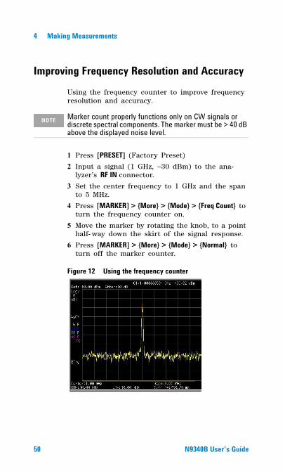
Using the frequency counter to improve frequency resolution and accuracy.
1 Press [PRESET] (Factory Preset)
2 Input a signal (1 GHz, –30 dBm) to the ana-lyzer’s RF IN connector.
3 Set the center frequency to 1 GHz and the span to 5 MHz.
4 Press [MARKER] > {More} > {Mode} > {Freq Count} to turn the frequency counter on.
5 Move the marker by rotating the knob, to a point half- way down the skirt of the signal response.
6 Press [MARKER] > {More} > {Mode} > {Normal} to turn off the marker counter.
Figure 12 Using the frequency counter
NOTE Marker count properly functions only on CW signals or discrete spectral components. The marker must be > 40 dB above the displayed noise level.
50 N9340B User�s Guide
Making Measurements 4
Making Distortion Measurements
This section provides information on measuring and identifying signal distortion.
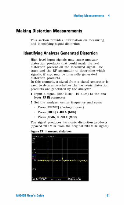
Identifying Analyzer Generated DistortionHigh level input signals may cause analyzer distortion products that could mask the real distortion present on the measured signal. Use trace and the RF attenuator to determine which signals, if any, may be internally generated distortion products.In this example, a signal from a signal generator is used to determine whether the harmonic distortion products are generated by the analyzer.
1 Input a signal (200 MHz, –10 dBm) to the ana-lyzer RF IN connector.
2 Set the analyzer center frequency and span:
� Press [PRESET] (factory preset)
� Press [FREQ] > 400 > {MHz}� Press [SPAN] > 700 > {MHz}
The signal produces harmonic distortion products (spaced 200 MHz from the original 200 MHz signal)
Figure 13 Harmonic distortion
N9340B User�s Guide 51
4 Making Measurements
3 Change the center frequency to the value of the second (400 MHz) harmonic:
� Press [MARKER] > {Peak Search}� Press [MARKER] > {Marker To} > {To Center}
4 Change the span to 50 MHz and re- center the signal:
� Press [SPAN] > 50 > {MHz}� Press [MARKER] > {Peak Search}
5 Set the attenuation to 0 dB:
� Press [AMPTD] > {Attenuation} > 0 > {dB}� Press [MARKER] > {Marker To} > {To Ref}
6 To determine whether the harmonic distortion products are generated by the analyzer, first save the trace data in trace 2 as follows:
� Press [TRACE] > {Trace (2)}� Press [TRACE] > {Clear Write}
7 Allow trace 2 to update (minimum two sweeps), then store the data from trace 2 and place a delta marker on the harmonic of trace 2:
� Press [TRACE] > {View}� Press [MARKER] > {Peak Search}� Press [MARKER] > {Delta}
The figure 14 shows the stored data in trace 2 and the measured data in trace 1. The Marker Delta indicator reads the difference in amplitude between the reference and active trace markers.
52 N9340B User�s Guide
Making Measurements 4
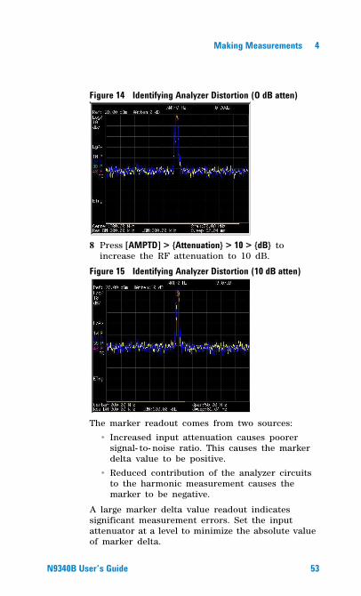
Figure 14 Identifying Analyzer Distortion (O dB atten)
8 Press [AMPTD] > {Attenuation} > 10 > {dB} to increase the RF attenuation to 10 dB.
Figure 15 Identifying Analyzer Distortion (10 dB atten)
The marker readout comes from two sources:
• Increased input attenuation causes poorer signal- to- noise ratio. This causes the marker delta value to be positive.
• Reduced contribution of the analyzer circuits to the harmonic measurement causes the marker to be negative.
A large marker delta value readout indicates significant measurement errors. Set the input attenuator at a level to minimize the absolute value of marker delta.
N9340B User�s Guide 53
4 Making Measurements
Third-Order Intermodulation DistortionTwo- tone, third- order intermodulation (TOI) distortion is a common test in communication systems. When two signals are present in a non- linear system, they may interact and create third- order intermodulation distortion products that are located close to the original signals. System components such as amplifiers and mixers generate these distortion products.
In this example we test a device for third- order intermodulation using markers. Two sources are used, one set to 300 MHz and the other to 301 MHz.
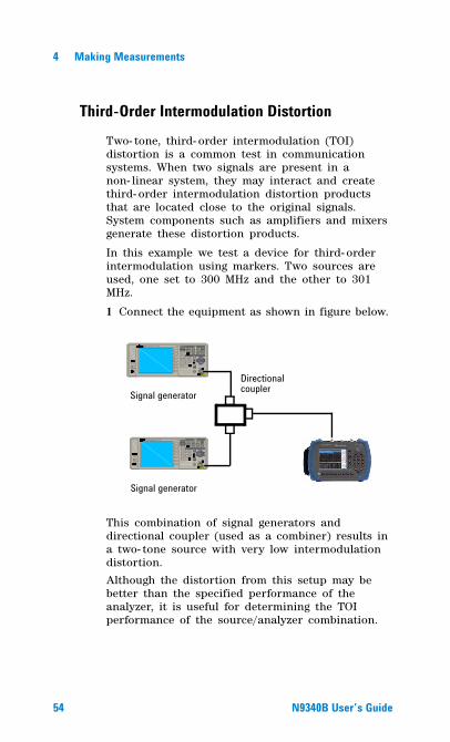
1 Connect the equipment as shown in figure below.
This combination of signal generators and directional coupler (used as a combiner) results in a two- tone source with very low intermodulation distortion.
Although the distortion from this setup may be better than the specified performance of the analyzer, it is useful for determining the TOI performance of the source/analyzer combination.
Frequency
Enter
7 MODOn/ Off
RF
4
1
0
2
9
6
3
On/Off
Amplitude FM
Utility
LF Out
Preset
Local
AM I/Q
File
TriggerPulseM
·
Sweep
8
5
Remote
StandbyOn
N9310A RF Signal Generator 9 kHz - 3.0 GHz
REVERSE PWR4W MAX 30 VDC
LF OUT RF OUT 50
FUNCTIONS
Frequency
Enter
7 MODOn/Off
RF
4
1
0
2
9
6
3
On/ Off
Amplitude FM
Utility
LF Out
Preset
Local
AM I/ Q
File
TriggerPulseM
·
Sw eep
8
5
Remote
StandbyOn
N9310A RF Signal Generator 9 kHz - 3.0 GHz
REVERSE PWR4W MA X 30VDC
LF OUT RF OUT 50
FUNCTIONS
Signal generator
Signal generatorDirectional coupler
54 N9340B User�s Guide
Making Measurements 4
After the performance of the source/analyzer combination has been verified, the DUT (device under test, for example, an amplifier) would be inserted between the directional coupler output and the analyzer input.
2 Set one source (signal generator) to 300 MHz and the other source to 301 MHz. This will define the frequency separation at 1 MHz. Set both sources equal in amplitude, as measured by the analyzer. In this example, they are both set to –5 dBm.
3 Set the analyzer center frequency and span:
� Press [PRESET] (Factory preset)
� Press [FREQ] > 300.5 > {MHz}� Press [SPAN] > 5 > {MHz}
4 Reduce the RBW until the distortion products are visible:
� Press [BW/SWP] > {RBW}, and reduce the RBW using the knob, the arrow keys or the numeric keypad.
5 Move the signal to the reference level:
� Press [MARKER] > {Peak Search}� Press [MARKER] > {Marker To} > {To Ref}
6 Reduce the RBW until the distortion products are visible:
� Press [BW/SWP] > {RBW}, and reduce the RBW using the knob, the arrow keys or the numeric keypad.
7 Activate the second marker and place it on the peak of the distortion product (beside the test signal) using the Next Peak:
� Press [MARKER] > {Delta}
NOTE The coupler used should have a high isolation between the two input ports to limit the sources intermodulation.
N9340B User�s Guide 55
4 Making Measurements
� Press [MARKER] > {Peak Search} > {Next Left (Right) PK}
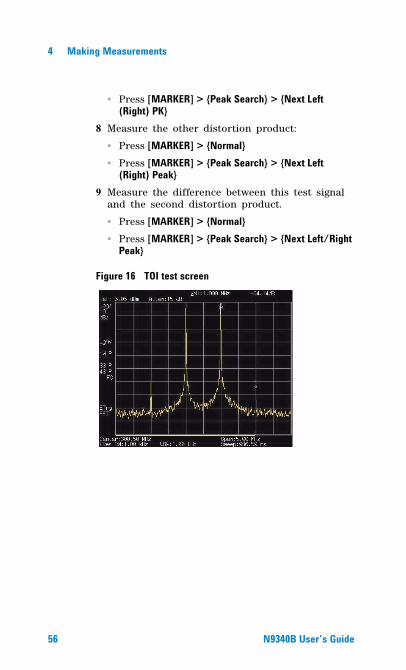
8 Measure the other distortion product:
� Press [MARKER] > {Normal}� Press [MARKER] > {Peak Search} > {Next Left
(Right) Peak}9 Measure the difference between this test signal
and the second distortion product.
� Press [MARKER] > {Normal}� Press [MARKER] > {Peak Search} > {Next Left/Right
Peak}
Figure 16 TOI test screen
56 N9340B User�s Guide
Making Measurements 4
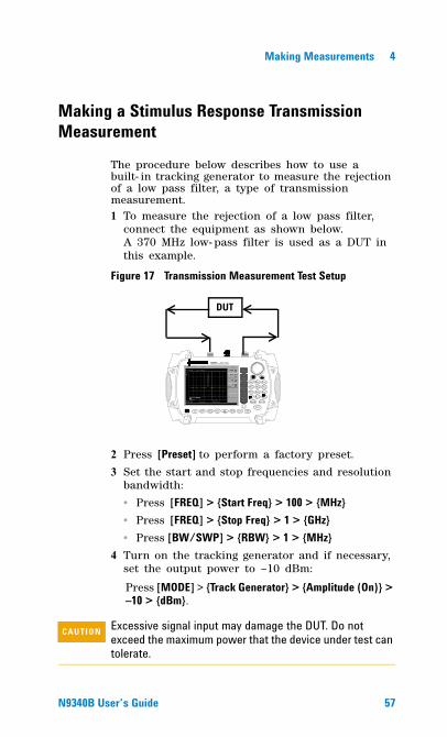
Making a Stimulus Response Transmission Measurement
The procedure below describes how to use a built- in tracking generator to measure the rejection of a low pass filter, a type of transmission measurement.1 To measure the rejection of a low pass filter,
connect the equipment as shown below. A 370 MHz low- pass filter is used as a DUT in this example.
Figure 17 Transmission Measurement Test Setup
N9340A HANDHELD SPECTRUM ANALYZER
100 kHz - 3.0 GHz
PRESET
ENTER
FREQ SPANAMPTDBW/SWPSYS MODE MEAS TRACE
ESC/ CLR
2 DEF 3 GHI1ABC
5M NO4JKL 6PQR
8VWX7STU 9 YZ_
0SAVE LIM IT
M ARKER
DUT
2 Press [Preset] to perform a factory preset.
3 Set the start and stop frequencies and resolution bandwidth:
� Press [FREQ] > {Start Freq} > 100 > {MHz}� Press [FREQ] > {Stop Freq} > 1 > {GHz}� Press [BW/SWP] > {RBW} > 1 > {MHz}
4 Turn on the tracking generator and if necessary, set the output power to –10 dBm:
Press [MODE] > {Track Generator} > {Amplitude (On)} > �10 > {dBm}.
CAU-CAUTION Excessive signal input may damage the DUT. Do not exceed the maximum power that the device under test can tolerate.
N9340B User�s Guide 57
4 Making Measurements
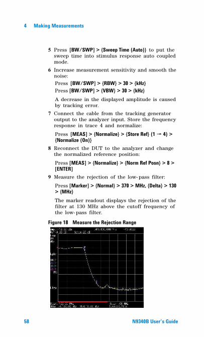
5 Press [BW/SWP] > {Sweep Time (Auto)} to put the sweep time into stimulus response auto coupled mode.
6 Increase measurement sensitivity and smooth the noise:Press [BW/SWP] > {RBW} > 30 > {kHz}Press [BW/SWP] > {VBW} > 30 > {kHz}A decrease in the displayed amplitude is caused by tracking error.
7 Connect the cable from the tracking generator output to the analyzer input. Store the frequency response in trace 4 and normalize:
Press [MEAS] > {Normalize} > {Store Ref} (1→ 4) > {Normalize (On)}
8 Reconnect the DUT to the analyzer and change the normalized reference position:
Press [MEAS] > {Normalize} > {Norm Ref Posn} > 8 > [ENTER]
9 Measure the rejection of the low- pass filter:
Press [Marker] > {Normal} > 370 > MHz, {Delta} > 130 > {MHz}The marker readout displays the rejection of the filter at 130 MHz above the cutoff frequency of the low- pass filter.
Figure 18 Measure the Rejection Range
58 N9340B User�s Guide
Making Measurements 4
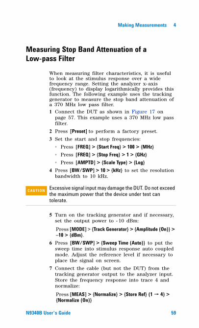
Measuring Stop Band Attenuation of a Low-pass Filter
When measuring filter characteristics, it is useful to look at the stimulus response over a wide frequency range. Setting the analyzer x- axis (frequency) to display logarithmically provides this function. The following example uses the tracking generator to measure the stop band attenuation of a 370 MHz low pass filter.1 Connect the DUT as shown in Figure 17 on
page 57. This example uses a 370 MHz low pass filter.
2 Press [Preset] to perform a factory preset.
3 Set the start and stop frequencies:
� Press [FREQ] > {Start Freq} > 100 > {MHz}� Press [FREQ] > {Stop Freq} > 1 > {GHz}� Press [AMPTD] > {Scale Type} > {Log}
4 Press [BW/SWP] > 10 > {kHz} to set the resolution bandwidth to 10 kHz.
5 Turn on the tracking generator and if necessary, set the output power to - 10 dBm:
Press [MODE] > {Track Generator} > {Amplitude (On)} > �10 > {dBm}.
6 Press [BW/SWP] > {Sweep Time (Auto)} to put the sweep time into stimulus response auto coupled mode. Adjust the reference level if necessary to place the signal on screen.
7 Connect the cable (but not the DUT) from the tracking generator output to the analyzer input. Store the frequency response into trace 4 and normalize:
Press [MEAS] > {Normalize} > {Store Ref} (1→ 4) > {Normalize (On)}
CAU-CAUTION Excessive signal input may damage the DUT. Do not exceed the maximum power that the device under test can tolerate.
N9340B User�s Guide 59
4 Making Measurements
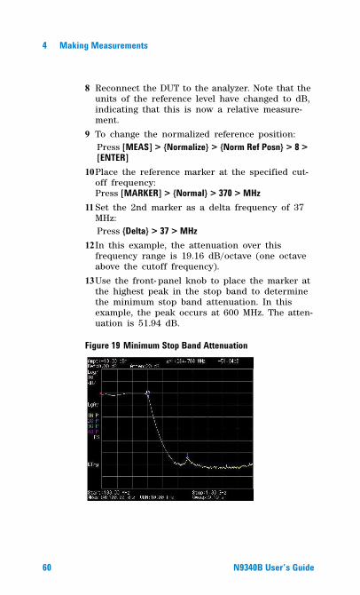
8 Reconnect the DUT to the analyzer. Note that the units of the reference level have changed to dB, indicating that this is now a relative measure-ment.
9 To change the normalized reference position:Press [MEAS] > {Normalize} > {Norm Ref Posn} > 8 > [ENTER]
10Place the reference marker at the specified cut-off frequency: Press [MARKER] > {Normal} > 370 > MHz
11 Set the 2nd marker as a delta frequency of 37 MHz:Press {Delta} > 37 > MHz
12In this example, the attenuation over this frequency range is 19.16 dB/octave (one octave above the cutoff frequency).
13Use the front- panel knob to place the marker at the highest peak in the stop band to determine the minimum stop band attenuation. In this example, the peak occurs at 600 MHz. The atten-uation is 51.94 dB.
Figure 19 Minimum Stop Band Attenuation
60 N9340B User�s Guide
Making Measurements 4
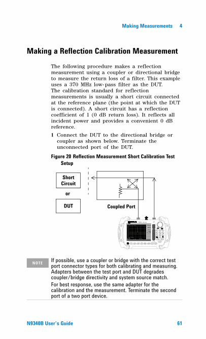
Making a Reflection Calibration Measurement
The following procedure makes a reflection measurement using a coupler or directional bridge to measure the return loss of a filter. This example uses a 370 MHz low- pass filter as the DUT.The calibration standard for reflection measurements is usually a short circuit connected at the reference plane (the point at which the DUT is connected). A short circuit has a reflection coefficient of 1 (0 dB return loss). It reflects all incident power and provides a convenient 0 dB reference.
1 Connect the DUT to the directional bridge or coupler as shown below. Terminate the unconnected port of the DUT.
Figure 20 Reflection Measurement Short Calibration Test Setup
N9340A HANDHELD SPECTRUM ANALYZER
100 kH z - 3.0 GHz
PRESET
ENTER
FREQ SPANAM PTDBW/SWPSYS M ODE M EAS TRACE
ESC/ CLR
2 DEF 3 GHI1 ABC
5M NO4 JKL 6PQR
8 VWX7 STU 9 YZ_
0SAVE LIM IT
M ARKER
Coupled Port
Short Circuit
DUT
or
NOTE If possible, use a coupler or bridge with the correct test port connector types for both calibrating and measuring. Adapters between the test port and DUT degrades coupler/bridge directivity and system source match.For best response, use the same adapter for the calibration and the measurement. Terminate the second port of a two port device.
N9340B User�s Guide 61
4 Making Measurements
2 Connect the tracking generator output of the analyzer to the directional bridge or coupler.
3 Connect the analyzer input to the coupled port of the directional bridge or coupler.
4 Press [Preset] to perform a factory preset.
5 Turn on the tracking generator and if necessary, set the output power to –10 dBm:
Press [MODE] > {Track Generator} > {Amplitude (On)} > �10 > {dBm}
6 Set the start and stop frequencies and resolution bandwidth:
� Press [FREQ] > {Start Freq} > 100 > {MHz}� Press [FREQ] > {Stop Freq} > 1 > {GHz}� Press [BW/Avg] > 1 > MHz
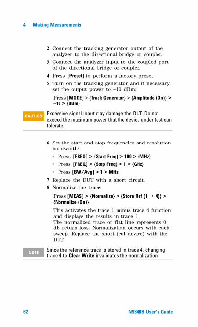
7 Replace the DUT with a short circuit.
8 Normalize the trace:
Press [MEAS] > {Normalize} > {Store Ref (1→ 4)} > {Normalize (On)}This activates the trace 1 minus trace 4 function and displays the results in trace 1. The normalized trace or flat line represents 0 dB return loss. Normalization occurs with each sweep. Replace the short (cal device) with the DUT.
CAU-CAUTION Excessive signal input may damage the DUT. Do not exceed the maximum power that the device under test can tolerate.
NOTE Since the reference trace is stored in trace 4, changing trace 4 to Clear Write invalidates the normalization.
62 N9340B User�s Guide
Making Measurements 4
Figure 21 Short Circuit Normalized
N9340B User�s Guide 63
4 Making Measurements
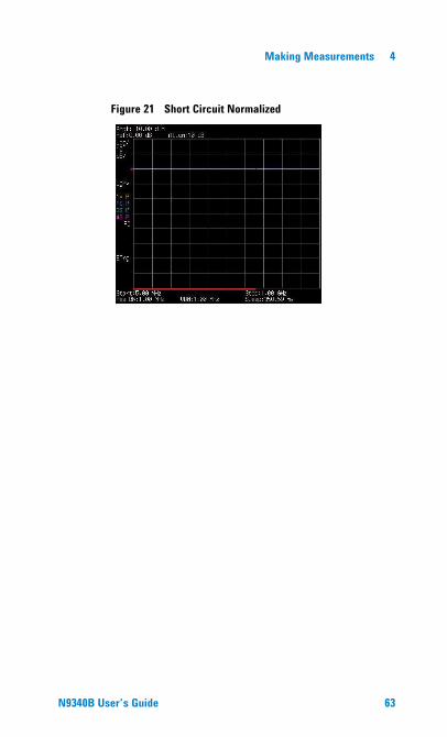
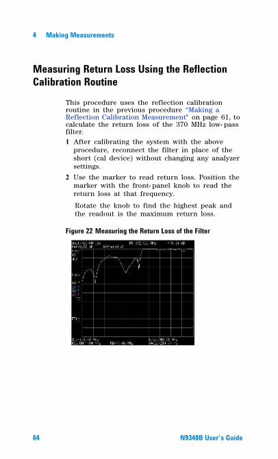
Measuring Return Loss Using the Reflection Calibration Routine
This procedure uses the reflection calibration routine in the previous procedure “Making a Reflection Calibration Measurement" on page 61, to calculate the return loss of the 370 MHz low- pass filter.1 After calibrating the system with the above
procedure, reconnect the filter in place of the short (cal device) without changing any analyzer settings.
2 Use the marker to read return loss. Position the marker with the front- panel knob to read the return loss at that frequency.
Rotate the knob to find the highest peak and the readout is the maximum return loss.
Figure 22 Measuring the Return Loss of the Filter
64 N9340B User�s Guide
Making Measurements 4
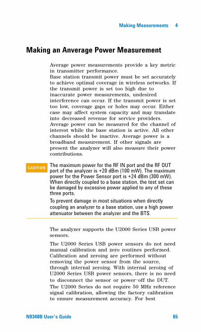
Making an Anverage Power Measurement
Average power measurements provide a key metric in transmitter performance.Base station transmit power must be set accurately to achieve optimal coverage in wireless networks. If the transmit power is set too high due to inaccurate power measurements, undesired interference can occur. If the transmit power is set too low, coverage gaps or holes may occur. Either case may affect system capacity and may translate into decreased revenue for service providers.Average power can be measured for the channel of interest while the base station is active. All other channels should be inactive. Average power is a broadband measurement. If other signals are present the analyzer will also measure their power contributions.
The analyzer supports the U2000 Series USB power sensors.
The U2000 Series USB power sensors do not need manual calibration and zero routines performed. Calibration and zeroing are performed without removing the power sensor from the source, through internal zeroing. With internal zeroing of U2000 Series USB power sensors, there is no need to disconnect the sensor or power-off the DUT. The U2000 Series do not require 50 MHz reference signal calibration, allowing the factory calibration to ensure measurement accuracy. For best
CAU-CAUTION The maximum power for the RF IN port and the RF OUT port of the analyzer is +20 dBm (100 mW). The maximum power for the Power Sensor port is +24 dBm (300 mW). When directly coupled to a base station, the test set can be damaged by excessive power applied to any of these three ports.To prevent damage in most situations when directly coupling an analyzer to a base station, use a high power attenuator between the analyzer and the BTS.
N9340B User�s Guide 65
4 Making Measurements
accuracy, users are recommended to perform external zeroing for input signals below -30 dBm for best accuracy.
Making a Basic Average Power MeasurementTo make an average power measurement, connect the power sensor and cable, zero and calibrate the meter, before making a measurement.Zeroing of the Power Meter will occur automatically:
• Every time the Power Meter functon is used.
• When a 5 degree C. change in instrument temperature occurs.
• Whenever the power sensor is changed.
• Every 24 hours (min.).
• Before measuring low level signals -for example, 10 dB above the lowest specified power the power sensor is capable of.
Calibrating the Power Meter every time you cycle the power on and off.In most situations, you can press {Zero} to complete the two steps (zero and cal) together.
NOTE If you suspect other signals may be present, it is recommended that you turn off all the other channels and measure average power only on the signal of interest.Another option is to measure channel power (which is less accurate), that filters out all other channels (signals). You can measure channel power for CDMA using the CDMA Analyzer or CDMA Over Air tool. For other modulation formats, use their respective analyzers (that is, GSM, 1xEV-DO, or W-CDMA) or measure channel power using either the spectrum analyzer or the Channel Scanner tool.
NOTE Connect the power meter as close as possible to the power amplifier/duplexer output. Do not use a coupled port. Sensors may not be as accurate at the power levels provided by coupled ports.
66 N9340B User�s Guide
Making Measurements 4
To Make a Basic Anverage Power MeasurementYou can follow the steps below to make a basic average power measurement.
1 Press [Preset] to perform a factory preset.
2 Press [MODE] > {Power Meter} > [ENTER] to turn on the power meter.
3 Zero and calibrate the meter. Press {Zeroing} to make a Zero operation of the power sensor followed by a calibration operation.
4 Connect the power sensor to the power Ref 50 MHz port. The anaylzer supports the U2000 Series power sensors.
5 Connect the external attenuation, if required, with the power sensor used.
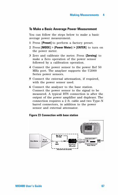
6 Connect the analyzer to the base station. Connect the power sensor to the signal to be measured. A typical BTS connection is after the output of the power amplifier and duplexer. The connection requires a 2 ft. cable and two Type- N barrel connectors, in addition to the power sensor and external attenuator.
Figure 23 Connection with base station
N9340B User�s Guide 67
4 Making Measurements
Setting Power Meter ResolutionYou can choose from four levels of Power Meter resolution. Higher resolutions provide more accuracy but slow the measurement speed.
1 Press [Preset] to perform a factory preset.
2 Press [MODE] > {Power Meter} > [ENTER] to turn on the power meter.
3 Press {Meas Disp} > {Resolution}. Select 1,2,3 or 4. The four options represent different resolution as follow:
• [1] = 1
• [2] = 0.1
• [3] = 0.01
• [4] = 0.001
Setting the Power Meter�s Top and Bottom End-PointsSetting the end points (Disk Range) close to expected measurement value changes the sensitivity of the Power Meter scale resolution. This is an advantage in viewing small changes in power. However, this will not affect the overall range of the sensor.
1 Press [Preset] to perform a factory preset.
2 Press [MODE] > {Power Meter} > [ENTER] to turn on the power meter.
3 Press {Meas Disp} > {Disp Range} to access the end- points menu.
4 Press {Top} and enter the maximum scale value desired using the numeric keypad. Then press {dBm} to complete the setup.
5 Press {Bottom} and enter the minimum scale value desired using the numeric keypad. Then press {dBm} to complete the setup.
68 N9340B User�s Guide
Making Measurements 4
Setting the Power Meter�s Upper and Lower LimitsThe internal Power Meter can be configured to detect when a measurement has failed a user predefined upper and lower limits.
1 Press [Preset] to perform a factory preset.
2 Press [MODE] > {Power Meter} > [ENTER] to turn on the power meter.
3 Press {Meas Setup} > {Limits} to access the limits menu.
4 Press {Limits} to activate the limits function. Each time the softkey is pressed, the selected option changes.
5 Press {Upper Limits} and enter the high limit value using the numeric keypad. Then press {dBm} to complete the setup.
6 Press {Lower Limits} and enter the low limit value using the numeric keypad. Then press {dBm} to complete the setup.
N9340B User�s Guide 69
4 Making Measurements
Demodulate the AM and FM signals
The N9340B provide you the AM and FM demodulation function.
Demodulating an AM SignalThe demodulation functions listed in the menu under [SPAN] > {Demod} allow you to demodulate and hear signal information displayed on the analyzer.
Simply place a marker on a signal of interest, set the analyzer in zero span, activate AM demodulation, turn the speaker on, and then listen.
1 Press [Preset], (Factory Preset).
2 Connect an antenna to the analyzer input.
3 Select a frequency range on the analyzer, such as the range for AM radio broadcasts. For example, the frequency range for AM broadcasts in the United States is 550 kHz to 1650 kHz:Press [FREQ] > {Start Freq} > 550 > {kHz} > {Stop Freq} > 1650 {kHz}.
4 Place a marker on the signal of interest:Press [Marker] > {Peak Search} > {Next Pk Right} or {Next Pk Left}
5 Set the frequency of the signal of interest to center frequency:Press [Marker] > {Peak Search} > {Next Pk Right} or Next Pk Left (as necessary).
6 Reduce the span to 1 MHz by press [SPAN] > 1 > {MHz} and [Maker] > {Marker To} > {To Center}, keeping the signal of interest in the center of the display with 1 MHz span.
7 Set the analyzer into time- domain with zero span:
NOTE The demod submenu is only available in zero span. Press [SPAN] > {Zero} before using demodulation function.
70 N9340B User�s Guide
Making Measurements 4
8Press [SPAN] > {Zero}.
9 Change the resolution bandwidth to 100 kHz:
Press [BW/SWP] > 100 > {kHz}.10Set the top of the signal near the top of the dis-
play by changing the reference level with the front- panel knob:
Press [AMPTD], rotate front- panel knob.
11 Set the amplitude scale to linear and then re- adjust the reference level to keep the signal centered in the display:
Press [AMPTD] > {Scale Type (Lin)}.Press [AMPTD], rotate front- panel knob.
12Set the detector type to sample and turn on AM demodulation:Press [TRACE] > {More} > {Detector} > {Sample}.Press [SPAN] > {Demod} > {AM ON}.
13Listen to the demodulated AM signal (adjust the volume as necessary):Press [SPAN] > {Demod} > {Speaker Vol}, rotate front- panel knob.
14Measure the modulation index (AM depth as a percentage):Press {Sweep Time} > 5 > {s}.
Press [BW/SWP] > {Video BW} > 30 > {Hz}.Press [AMPTD] (use the front- panel knob to adjust the trace to the middle of the screen).
Press [BW/SWP] > {Video BW} > 100 > {Hz}.Press [BW/SWP] > {Sweep Time} > 5 > {ms}.
The middle horizontal graticule line represents 0% AM; the top and bottom horizontal lines represent 100% AM.
N9340B User�s Guide 71
4 Making Measurements
Demodulating an FM SignalThis section demonstrates how to demodulate and listen to an FM signal using the built- in FM demodulator.Using the built in FM demodulator you can tune to an FM signal and view the results of the detector output as displayed in the timedomain. Alternatively, the demodulated signal is also available as an audio output (to the speaker or headphone jack).
1 Perform a factory preset:S
Press [Preset] (Factory Preset, if present).2 Use a signal source or an antenna for an FM
signal to analyze. In this example the signal source is used transmitting at 300 MHz with FM deviation of 10 kHz and FM rate of 1 kHz.
3 Set the center frequency to the center of the FM signal (in this case 300 MHz):
Press [FREQ] > 300 > {MHz}.4 Set the analyzer to zero span for time- domain
analysis:
Press [SPAN] > {Zero Span}.Press [BW/SWP] > {Sweep Time} > 4 > {ms}.
5 Set the resolution bandwidth to capture the full bandwidth of the FM signal. To calculate the required bandwidth use
RBW =((2 x Frequency Deviation)+(2 x Modulation Rate))
In our case the RBW should be: (2 x 10 kHz) + (2 x 1 kHz) = 22 kHz With 1- 3- 10 sequence RBW selections, choose the next highest RBW of 30 kHz:
Press [BW/SWP] > 30 > {kHz}.
NOTE If you are using a broadcast FM signal in the United States, for example, the FM channels are broadcasting between 87.7 MHz to 107.7 MHz.
72 N9340B User�s Guide
Making Measurements 4
6 Turn on the FM demodulator:
Press [SPAN] > {Demod} > {FM ON}.Listen to the FM signal.
Press [SPAN] > {Demod} > {Speaker Vol}, rotate the knob.
Adjust the volume of the internal speaker with the volume knob on the front- panel. Alterna-tively you can also use the headphone jack.
NOTE The option AMA provide the AM/FM modulation analysis mode by pressing [MODE] > {Demodulation Analysis} to measure the modulation rate and other related parameters.
N9340B User�s Guide 73

4 Making Measurements
74 N9340B User�s Guide
Agilent N9340B Handheld Spectrum Analyzer
5Key Reference
This Chapter provides descriptions of the Instrument hardkeys and softkey menu functionality, key access to softkey sub- menus, and instrument parameter control options.
Additional reference information is provided in the Menu Maps section.
75Agilent Technologies
5 Key Reference
Amplitude
Key access: [AMPTD]Activates the reference level function and access the associated softkeys to set functions that affect the way data on the vertical axis is displayed or corrected.
Ref levelKey access: [AMPTD] > {Ref level}Activates the reference level function.
The reference level is the amplitude power or voltage represented by the top graticule on the display. Changing the value of the reference level changes the absolute amplitude level (in the selected amplitude units) of the top graticule line. To change the reference level, use the arrow keys, the knob, or the numeric keypad. Pressing any digit (0 through 9) on the numeric keypad brings up the terminator menu.
AttenuationKey access: [AMPTD] > {Attenuation}Toggles the input attenuation between Auto or Man.
The input attenuation ranges from 1 dB to 51 dB and allows you to set the attenuation level in 1 dB increments when attenuation is set to Man.
The input attenuator, normally coupled to the reference level control, reduces the power level of the analyzer input signal at the input mixer. The attenuator is recoupled when attenuation is set to Auto.
CAU-CAUTION To prevent damage to the input mixer, do not exceed a power level of +33 dBm at the input. A granted power level for stable sensitive measurement is less than 20dBm.
76 N9340B User�s Guide
Key Reference 5
PreampKey access: [AMPTD] > {Preamp}
Toggles the internal preamp between On and Off.Preamp results in a correction being applied to compensate for the gain of the preamp at 20 dBm so that amplitude readings show the actual value at the input connector.
The preamp is set to on in frequency bands from 1 MHz to 3 GHz, otherwise the correction is not applied even though the PA indication still appears.
Scale/DIVKey access: [AMPTD]Sets the logarithmic units per vertical graticule division on the display.
Scale TypeKey access: [AMPTD] > {Scale Type}Toggles the scale type of vertical graticule divisions between logarithmic and linear.
When Scale Type is set to Log, a logarithmic units is activated ranging from 1 to 10 dB per division.
When Scale Type is set to Lin, the vertical divisions are linearly scaled and the default amplitude units are volts. The top of the display is set to the reference- level value and the bottom graticule becomes zero volts. (Each division of the graticule is one- tenth of the reference level in volts.)
NOTE When the preamp is on, a PA indication appears on the left side of the display.
NOTE The Scale/Div function is only available when the Scale Type key is set to Log.
N9340B User�s Guide 77
5 Key Reference
HiSensitivityKey access: [AMPTD] > {HiSensitivity}Press this softkey On to set 0 dB attenuation, - 50 dBm reference level and turn the pre- amplifer on. It’s very helpful to observe the low- level signals with this settings.
Ref OffsetKey access: [AMPTD] > {Ref Offset}Adds an offset value which ranges from - 327.6 dB to +327.6 dB, to the displayed reference level.
Reference- level offsets are used when gain or loss occurs between a device under test and the analyzer input. Thus, the signal level measured by the analyzer may be referred to as the level at the input of an external amplitude conversion device. When an amplitude offset is entered, its value appears in the lower left corner of the display.
Y Axis UnitsKey access: [AMPTD] > {Y Axis Units}Sets the amplitude units.
NOTE Reference-level offsets are only entered by using the numeric keypad. Entering an offset does not affect the trace or the attenuation value.
NOTE Amplitude units are maintained for both logarithmic and linear modes depending on the Scale Type setting.
78 N9340B User�s Guide
Key Reference 5
MODE
Activates the softkey menus to select the measurement mode of your analyzer. The measurement modes are:
• Spectrum Analyzer
• Tracking Generator
• Power Meter
• Demodulation Analysis (Option N9340B - AMA) activated by License Key.
Spectrum AnalyzerKey access: [MODE] > {Tracking Generator}Select the spectrum analyzer mode, and press [ENTER] to make the spectrun analysis and measurement.
Tracking GeneratorKey access: [MODE] > {Tracking Generator}Select this mode, and press [ENTER] to make specified measurement with tracking generator. When selected, the Meas softkey menu for the tracking generator mode will appear.
AmplitudeKey access: [MODE] > {Tracking Generator } > {Amplitude}Activates (On) or deactivates (Off) the output power of the tracking generator. The power level can then be adjusted using the numeric keypad, arrow keys, or knob. Pressing any digit, 0 through 9, on the numeric keypad brings up the selected terminator menu.
N9340B User�s Guide 79
5 Key Reference
Amptd StepKey access: [MODE] > {Tracking Generator } > { Amptd Step}Allows you to set the step size of the power level range of the tracking generator. The default setting is one vertical scale division when in a logarithmic amplitude scale.
Amptd OffsetKey access: [MODE]>{Tracking Generator}> { Amptd Offset}Offsets the displayed power of the tracking generator. Using the amplitude offset capability of the tracking generator allows you to take system losses or gains into account, thereby displaying the actual power delivered to the device under test.
NormalizeKey access: [MODE]>{Tracking Generator } > {Normalize}
� Store Ref (1→ 4)Copies trace 1 into trace 4. Store Ref(1→ 4) must be pressed before pressing Normalize(On). If Normalize(On) is pressed before Store Ref(1→ 4),
CAU-CAUTION Power-level sensitive devices connected to the tracking generator output may be accidentally damaged. This is because the actual source amplitude will be greater than the amplitude indicated on the analyzer, when the power sweep function is being used. The source amplitude value is used as the starting amplitude for a power sweep. The ending amplitude for a power sweep is higher then the source amplitude value and it may actually be set to val-ues beyond specified output levels. Therefore, exercise caution when connecting a power-level sensitive device to the tracking generator output.
NOTE When Amplitude (Off) is selected, the output attenuation on the N9340B is set to the maximum attenuation.
80 N9340B User�s Guide
Key Reference 5
the error message: Store reference trace before turning on Normalize(On) is displayed in the status line, however Normalize has been activate.
� NormalizeNormalize(On) activates the normalize function. On each sweep, the normalized trace (Trace 4) is subtracted from Trace 1 and the result is added to the normalized reference level. The display shows the result of the following calculation:
Trace 1 - Normalized Trace + Normalized Reference Level
The trace data is normalized with respect to the normalized reference level, even if the value of the normalized reference level is changed. This function remains in effect on all subsequent sweeps until it is turned off.
The normalize function is useful for applying correction data to a trace while making a stimulus response measurement using a tracking generator. Normalize will compensate for irregularities of the components used in the test setup, isolating the performance of the DUT. For example, connect the cables and use a thru line in place of the device (DUT) to be measured, between the tracking generator and the analyzer input. Notice that the frequency response is not perfectly flat, showing the response of the cables, as well as the flatness of both the tracking generator and the analyzer. Now press Store Ref(1→ 4), Normalize On. Notice that the displayed trace is now flat, or normalized. The position of the normalized trace can now be moved to a different position on the display by changing the normalized reference position. This may be useful if the device to be tested has positive gain,
NOTE Segmented sweep is not available when Normalize (On) is selected. Trace 1 should be in clear write mode prior to setting normalize to on.
N9340B User�s Guide 81
5 Key Reference
such as an amplifier. Now replace the thru line with the device under test, and an accurate measurement of the gain or loss can be made.
� Norm Ref LvlSets the level (in dB) of the normalized reference.
� Norm Ref PosnOffsets the displayed trace without affecting the instrument gain or attenuation settings. This allows the displayed trace to be moved without decreasing measurement accuracy.
� Ref TraceAllows you to view or blank the reference trace on the display.
Power MeterKey access: [MODE] > {Power Meter}Use the arrow keys to highlight the mode.
Select this mode, and press [ENTER] to make a measurement using the power meter function. When selected, the Power Meter softkey menu will be displayed and many of the instrument hardkeys will be disabled as they are not necessary for this mode.
ZeroingKey access: [MODE] > {Power Meter} > {Zeroing}Access the associated Zeroing submenu.
� ZeroingMake a Zero operation of the power sensor.
The U2000 Series USB Power Sensors have their sensor calibration tables stored in non- volatile memory which means that the reference calibration factor is automatically loaded upon power- up.
82 N9340B User�s Guide
Key Reference 5
� Zero TypeToggles the zeroing type of the Power Sensor between internal and external. When this type is set to EXT, pressing Zeroing will bring up a message which indicates the external signal need be pulled out. This setting is not affected by the preset in Power Meter menu.
Meas DispKey access: [MODE] > {Power Meter} > {Meas Disp}Access the Meas Disp submenu for defining the display range and resolution while in Power Meter mode.
� Disp RangeAccess the associated Disp Range submenu.
� Auto RangeToggles the auto range function between On and Off. When the Auto Range is set to On, the Top and Bottom value of the power meter’s display range will be set automatically according to the measurement data:
Top = Max. data + 0.5
Bottom = Min. data - 0.5
The default setting is Off.
� TopSet the top value of the power meter’ display range.
Range from (Bottom + 0.01) to 200 dBm.
The default value is 20 dBm.
� BottomSet the bottom value of the power meter’ display range.
Range from - 200 to (Top - 0.01) dBm.
The default value is - 70 dBm.
N9340B User�s Guide 83
5 Key Reference
� ResolutionAccess the associated Resolution submenu.
When the measurement suffix is W or %, this parameter represents the number of significant digits. When the measurement suffix is dB or dBm, 1 through 4 represents 1, 0.1, 0.01, and 0.001 dB respectively. The default value is 3.
� Disp ModeChange the display mode between Meter and Chart.
The default mode is Meter.
� Chart ViewAccess the Chart View submenu. This soft key is disabled when the measurement is in process or if the display mode is set to Meter.
This submenu is used to view the measurement chart.
� Home View the first 21 points of current measurement chart.
� End View the lastest 21 points of current measure-ment chart.
� Prev View the previous points of the chart.
� Next View the next points of the chart.
� Continue/PauseContinues or pauses the current measurement. When the measurement is in process, this softkey is displayed as “Pause”; when the measurement is paused, the softkey is displayed as “Continue”.
84 N9340B User�s Guide
Key Reference 5
Meas SetupKey access: [MODE] > {Power Meter} > {Meas Setup}Accesses the Meas Disp submenu which is used to configure the mesurement settings.
� FreqSets a frequency between 1 kHz and 90.0 GHz using the numeric keypad, arrow key or knob. If the frequency does not correspond directly to a frequency in the sensor calibration table, the power sensor calculates the calibration factor using linear interpolation.
� Power RangeAccesses the Power Range submenu.
� Auto RangeEnables and disable auto ranging. When auto ranging is ON, the power sensor selects the best measuring range for the measurement. When auto ranging is OFF, the power sensor remains in the current range and may be manually set by the user.
� RangeSelects the Lower or Upper of power ranges when the Auto Range is Off.
� LimitsAccesses the Limits submenu.
� LimitsEnables or disables the limit function.
� Upper LimitSets a value of the upper test limit for the current measurement. The units used are dependent on the current setting of power unit. When the measured power is greater than the value specified, a failure will be reported.
N9340B User�s Guide 85
5 Key Reference
� Lower LimitSets the lower test limit value for the current measurement. The units used are dependent on the current setting of power unit. When the measured power is less than the value specified, a failure will be reported.
� Limit BeepEnables or disables the limit beep.
� Rel/OffsetAccesses the Rel/Offset submenu.
� RelEnables the comparison of a measurement result to a reference value and sets a reference value on the current measured data.
� OffsetSets a value of the display offset on the current measurement, and enable or disable the display offset. The display offset is applied to the measurement signal after any math calculation.
� AverageAccesses the Average submenu.
� AverageEnables or disables the Average function.
� Avg CountSets a value of the filter length and to set the average count value to be Auto or Manual.
The power sensor automatically sets the number of readings averaged together to satisfy most power measurements averaging requirements. The number of average readings depends on the resolution and the power level settings the power sensor is currently using.
� Step DetectEnables or disables step detection. In AUTO filter mode, the average of the last four values entered into the filter is compared to the entire filter average. If the difference between the two
86 N9340B User�s Guide
Key Reference 5
averages is greater than 12.5%, the digital filter is cleared. The filter will then start storing new measurement data. This feature shortens the filter time required when the input power changes substantially. Note that the result appears to settle faster, although true settling to the final value is unaffected.
� Meas IntervalSets the interval time between two measurements. The default value is 100 ms.
PresetKey access: [MODE] > {Power Meter} > {Preset}Sets the Power Meter softkey menu options to the preset conditions. For example, the Upper and Lower Limits are set to their preset limit values.
N9340B User�s Guide 87
5 Key Reference
BW/SWP
Activates the bandwidth function and accesses the associated softkeys to control resolution bandwidth, video bandwidth and sweep time.
RBWKey access: [BW/SWP] > {RBW}Changes the 3 dB resolution bandwidth on the analyzer from 30 Hz to 1 MHz in a 1, 3, 10 sequence using the knob, step keys or the numeric keypad.
As the resolution bandwidth is decreased, the sweep time is modified to maintain amplitude calibration. Resolution bandwidth is also related to span. As span is decreased, resolution bandwidth decreases. As the resolution bandwidth changes, the video bandwidth, if in auto couple mode, changes to maintain the VBW/RBW ratio.
A “#”mark appears next to RBW on the display when it is not coupled.
VBWKey access: [BW/SWP] > {VBW}Changes the analyzer post- detector filter from 3 Hz to 1 MHz in a 1, 3, 10 sequence using the knob, the step keys, or the numeric keypad.
NOTE If an unavailable bandwidth is entered using the numeric keypad, the closest available bandwidth in the 1, 3, 10 sequence is used.
NOTE In non-zero span mode, the value of RBW is determined by whether the setting for RBW is Auto or Man (manual).
88 N9340B User�s Guide
Key Reference 5
As the video bandwidth is decreased, the sweep time is increased to maintain amplitude calibration.
VBW/RBWKey access: [BW/SWP] > {VBW/RBW}Selects the ratio between the video and resolution bandwidths.
If signal responses near the noise level are visually masked by the noise, the ratio can be set to less than 1 to lower the noise. The knob and step keys change the ratio in a 1, 3, 10 sequence.
Avg TypeKey access: [BW/SWP] > {Avg Type}Accesses the functions to automatically or manually choose from one of the following averaging type:
Log PwrKey access: [BW/SWP] > {Avg Type} > {Log Pwr}Averages the data as appropriate for the logarithmic scaled y- axis.
When average type is set to Log Pwr, “LgAv” appears on the left side of the display.
NOTE If an unavailable bandwidth entered using the numeric keypad, the closest available bandwidth in the 1, 3, 10 sequence is used.
NOTE When preset is set to default, or VBW/RBW is set to Auto, the ratio is set to 1.
N9340B User�s Guide 89
5 Key Reference
PwrKey access: [BW/SWP] > {Avg Type} > {Power}Converts the scale from logarithmic to linear power units, and then averages the power trace data.
With average type set to Pwr, “PAvg” appears on the left side of the display.
VoltageKey access: [BW/SWP] > {Avg Type} > {Voltage}Averages the data as appropriate for the linearly scaled y- axis scale.
With average type set to Voltage, “VAvg” appears on the left side of the display.
There are actually four types of averaging processes within an N9340B. All, except VBW filtering, are affected by this setting. They are listed as follows:
� Trace averagingAverages signal amplitudes on a trace- to- trace basis. (Press Log Pwr or Pwr)� Average detectorAverages signal amplitudes during the time or frequency interval and represents the result as a single measurement point.
� Noise markerAverages signal amplitudes across measurement points to reduce variations for noisy signals.
� VBW filteringPerforms a form of averaging of video signal.
90 N9340B User�s Guide
Key Reference 5
Sweep TimeKey access: [BW/SWP] > {Sweep Time}Selects the sweep time for the analyzer to tune across the displayed frequency span (or, in zero span, the time the analyzer take to sweep the full screen).Inputs may be made using the knob, the arrow keys, or numeric keypad.
In non-zero spansWhen the sweep time is auto- coupled, the analyzer selects the optimum (shortest) sweep time ranging from 10 ms to 1000 s. The auto selection is determined by three measurement settings:
• Frequency Span
• The selected Resolution Bandwidth
• The selected Video Bandwidth
Note that changing one of the three factors above will change the sweep time. The sweep time is in direct ratio to frequency span and is in reverse ratio to the selected resolution bandwidth and video bandwidth when auto- coupled.
In zero spanAuto- coupled does not funtion when in a zero span. The sweep time can only be set manually. The sweep time is selectable from 6 s to 200 s in zero span.
NOTE Reducing the sweep time increases the sweep rate.
CAU-CAUTION With sweep time set to a value less than the minimum auto-coupled value, an annotation �Data out of range� appears in the active function block and the sweep time is automatically converted to the minimum auto-coupled value.
N9340B User�s Guide 91
5 Key Reference
In FFT ModeIn FFT mode, the sweep time default is auto- coupled. The submenu, sweep time is invalid in FFT mode.
SweepKey access: [BW/SWP] > {Sweep}Activates the sweep mode function and accesses associated softkeys to select the trace sweep functions.
Sweep TypeKey access: [BW/SWP] > {Sweep}Toggles the analyzer between the continuous sweep mode and the single sweep mode.
� Sweep (Single) Puts the analyzer in a single sweep mode. In this mode, pressing [BW/SWP] > {Single Sweep} enables a sweep.
� Sweep (Cont) Performs one sweep after another as soon as it is triggered. Pressing [Preset] (When Preset Type is set to Default) or turning the power on, sets the sweep mode to continuous sweep as default.
Sweep ModeKey access: [BW/SWP] > {Sweep} > {Sweep Mode}An N9340B provides two sweep modes to meet different sweep time requirements:
� NormalActivates the default sweep mode.
� FastActivates the fast sweep mode.
92 N9340B User�s Guide
Key Reference 5
Fast sweep mode provides a fast measurement function that decreases the sweep time. Using Fast Sweep will decrease the measurement accuracy.
Single SweepKey access: [BW/SWP] > {Sweep} > {Single Sweep}When the analyzer is in continuous sweep mode and not in a measurement mode ([MEAS] > Measure Off), pressing [BW/SWP] > {Single Sweep} will change the sweep setting to single sweep. It will then begin a sweep after the trigger conditions are met. If the analyzer is already in single sweep, pressing [BW/SWP] > {Single Sweep} will execute a new sweep as soon as the trigger condition is met.
If Average is on ([TRACE] > {More} > {Average On}), pressing [BW/SWP] > {Single Sweep} will halt averaging of the current value, and then continue averaging from the current count number when a single sweep function triggers.
NOTE Fast sweep is valid only when span is no less than 50 MHz. Measurement data is not ganruanteed in fast sweep mode.
N9340B User�s Guide 93
5 Key Reference
Enter
Hardkey function:
• Terminates data entry and enters into the analyzer numerical values keyed from numeric keypad on the front panel.
• Terminate filename entries.
94 N9340B User�s Guide
Key Reference 5
ESC/CLR
Provides mainly two types of functions:
Clear• Clears any numeric entry and cancels the active
function.
• Clears any title entry and cause the title to revert to the previous name.
• Clears input or output overloads
• Clears error messages from the status line along the bottom of the display.
Association with other functionsProvides a permitted setting for triggering other functions such as:
• Activates LIMIT function for pass/fail judgements.
• Activates SAVE function for current trace saving.
CAU-CAUTION When pressing [ESC/CLR], the current parameter annotation in the lower left corner, which is an indicator of available settings of LIMT and SAVE, disappears.
N9340B User�s Guide 95
5 Key Reference
Frequency
Activates the center frequency function, and accesses the menu of frequency functions. The center frequency, or start and stop frequency values appear below the graticule on the display.
Center FrequencyKey access: [FREQ] > {Center Freq}Activates the center frequency function, which allows you to set the horizontal center of the display to a specified frequency.
Start FrequencyKey access: [FREQ] > {Start Freq}Sets the frequency at the left side of the graticule. The left and right sides of the graticule correspond to the start and stop frequencies. When these frequencies are activated, their values are displayed below the graticule in place of center frequency and span.
Stop FrequencyKey access: [FREQ] > {Stop Freq}Sets the frequency at the right side of the graticule. The left and right sides of the graticule correspond to the start and stop frequencies. When these frequencies are activated, their values are displayed below the graticule in place of center frequency and span.
NOTE When changing both the center frequency and the span, change the frequency first since the span can be limited by the frequency value.
96 N9340B User�s Guide
Key Reference 5
CF StepKey access: [FREQ] > {CF Step}Changes the step size for the center frequency function. Once a step size has been selected and the center frequency function is activated, the arrow keys change the center frequency by the step- size value. The step size function is useful for finding harmonics and sidebands beyond the current frequency span of the analyzer. When auto- coupled, the center size is set to one division (10 percent of the span).
N9340B User�s Guide 97
5 Key Reference
Marker
Accesses the marker control softkeys to select the type and number of markers. Markers are diamond- shaped characters that identify points of traces. Up to six pairs of markers may appear on the display simultaneously; only one pair can be controlled at a time. The marker that is controlled is called the “active” marker. Pressing [MARKER] activates the Normal menu key.
MarkerKey access: [MARKER] > {Marker}Selects one of the six possible markers. A marker that has already been selected will become active when it is turned on. If a marker has been turned on and assigned to a specific trace, it will become active on that trace if that marker is selected.
NormalKey access: [MARKER] > {Normal}Activates a single frequency marker at the center of the active trace if a marker is not already displayed. If a marker is displayed before the Normal function is enabled, the marker is enabled at the position of the selected marker. The marker number is indicated above the marker. The knob and/or arrow keys move the marker left or right. If a value is entered from the numeric keypad, the marker is moved to the trace point nearest to that value. Annotation in the active function block and in the upper right corner indicates the frequency and amplitude of the marker (time and amplitude, if in zero span.) Pressing Normal turns off the Delta function and moves the active marker to the delta marker position.
98 N9340B User�s Guide
Key Reference 5
DeltaKey access: [MARKER] > {Delta}Activates a second marker at the position of the first marker. (If no marker is present, two markers appear at the center of the display). The amplitude and frequency (or time) of the first marker is fixed. The marker number is indicated above the delta marker, and the same number is indicated with an R (for example, 1R) above the reference marker. Use the data controls to position the delta marker. Annotation in the active function block and in the upper- right corner of the display indicates the frequency (or time) and amplitude differences between the two markers. The markers will be turned off if the scale type is changed between log and linear.
OffKey access: [MARKER] > {Off}Turns off the active function markers.
NOTE Pressing Delta again moves the reference marker to the active marker position, so you are allowed to make delta measurements from differing reference points without having to turn off the makers and begin again.
NOTE The delta marker function permits signal-to-noise measurements provided the signal is a single spectral component (sinusoid). Place a normal marker on the signal, press Delta, place the delta marker in the noise, and activate Marker Noise. The indicated amplitude indicates signal-to-noise/Hz.
N9340B User�s Guide 99
5 Key Reference
Peak SearchPlace a marker on the highest peak based on the setting of the Search Criteria as follows:� PeakKey access: [MARKER] > {Peak Search}Place a marker on the highest peak.
� Next LF PeakKey access: [MARKER] > {Peak Search} > {Next Left PK}Moves the marker to the next peak to the left of the current marker. The signal peak must exceed the peak threshold value by the peak excursion value. If there is no peak to the right, the marker will not move and the No Peak Found error message will appear on the display.
� Next RT PeakMoves the marker to the next peak to the right of the current marker. The signal peak must exceed the peak threshold value by the peak excursion value. If there is no peak to the right, the marker will not move and the No Peak Found error message will appear on the display.
Key access: [MARKER] > {Peak Search} > {Next Right PK}
� Auto SearchIn non- zero span, pressing Auto Search turns all six markers on and puts them on the six highest peak in the current frequency span.
In zero span, the function is not available.
Key access: [MARKER] > {Peak Search} > {Auto Search}
100 N9340B User�s Guide
Key Reference 5
Marker ToAccesses the following marker function menu keys:
� To CenterKey access: [MARKER] > {To Center}Sets the center frequency of the analyzer to the marker frequency. In Delta mode, pressing [Marker] > {Marker To} > {To Center} sets the center frequency to the marker delta value. The function is not available in zero span.
� To RefKey access: [MARKER] > {Marker To} Changes the reference level to the active marker value, moving the marked point to the reference level (top line of the graticule). In Delta mode, pressing [Marker] > {Marker To} > {To Ref} sets the reference level to the amplitude difference between the markers.
ModeKey access: [MARKER] > {More} > {Mode}Accesses the following menu keys that allows you to change the active marker readout mode.� Normal
Activates the default readout mode. � Freq Count
Activates a frequency counter mode.� Noise
Activates a noise readout mode for evaluating power density.
NOTE When the frequency scale is in log mode, the center frequency is not at the center of the display.
N9340B User�s Guide 101
5 Key Reference
Marker TraceKey access: [MARKER] > {More} > {Marker Trace}Activates a marker on the trace if there are no markers turned on. If a marker is currently active, press Marker Trace until 1, 2, 3, or 4 is underlined. The active marker will be moved to the selected trace.
Selecting Auto will move the marker to the automatically selected trace. The selection order is to look for the lowest numbered trace in the following order of trace modes:
If there is no trace in any of these modes, it selects trace 1 as default.
All OffKey access: [MARKER] > {More} > {All Off}Turns off all of the markers, including markers used for signal track and demodulation. The marker annotation is also removed.
NOTE Frequency counter is properly effective only on CW signals or discrete peaks. For a valid reading, the marker must be greater than 25 dB above the noise. Freq Count function is not supported under Marker Delta condition.
NOTE Noise mode operates only on noise peaks and not supported under Marker Delta condition.
Clear write Max holdMin. hold View
102 N9340B User�s Guide
Key Reference 5
MEAS
Hardkey menu access.
In spectrum analysis mode, pressing [MEAS] brings up the menu for a suite of power measurements such as adjacent channel power, occupied bandwidth, and channel power.
OBWOccupied Bandwidth (OBW) integrates the power of the spectrum in the displayed green frame. The measurement defaults to 99% of the occupied bandwidth power.Occupied bandwidth measurement are made in either single or continuous sweep mode.
Selecting a MethodPress [MEAS] > {OBW} > {Method} to toggle the occupied bandwidth measurement mode between percentage (%) and dBc.
• Setting Percentage (%)
Press {OBW} > {Method} > {Percent} to edit the percentage of signal power used when determining the occupied bandwidth. Press {%} to set the percentage ranging from 10.00% to 99.99%.
• Setting dBcPress {OBW} > {Method} > {dBc} to specify the power level used to determine the emission bandwidth as the number of dB down from the highest signal peak, within the occupied bandwidth span. This function is an independent calculation from the OBW calculation. The x dB bandwidth result is also called the emissions bandwidth (EBW). This sets the green frame (f1 and f2 are the two cross points of the signal and the pair of vertical lines of the displayed green frame) to your specified dB value below the maximum power, and compute the total power in the frame. The emission bandwidth is then calculated ranging from 0.1 dB to 100 dB (the default value is set to 26 dB).
N9340B User�s Guide 103
5 Key Reference
ACPRThe adjacent channel power ratio (ACPR) measures the power ratio between the main channel power and the adjacent channel power.
ACPR measures the total power (rms voltage) in the specified channel. The measurement result reports the ratios of the two adjacent channel powers to the main channel power.
Center FrequencyKey access: [MEAS] > {ACPR} > {Center Freq}Sets the center frequency of the main channel power.
Main ChannelKey access: [MEAS] > {ACPR} > {Main Channel}Specifies the range of integration used in calculating the power in the main channel. Use the knob, the arrow keys, or the numeric keypad to set
the bandwidth.
Adjacent ChannelKey access: [MEAS] > {ACPR} > {Adj Channel}Specifies the range of integration used in calculating the power in the adjacent channel. Use the knob, the arrow keys, or the numeric keypad to
set the bandwidth.
Channel SpaceKey access: [MEAS] > {ACPR} > {Channel Space}Sets the space value between the center frequency of main channel power and that of the adjacent channel power.
104 N9340B User�s Guide
Key Reference 5
Channel PowerChannel power function measures the power and power spectral density in the channel bandwidth specified. One pair of vertical lines of the displayed green frame indicates the edges of the channel bandwidth. The center frequency, reference level, and channel bandwidth must be set by the user.The power calculation method used to determine the channel power is a traditional method known as the integration bandwidth (IBW) method. A swept spectrum is used as the basis for this calculation. Therefore, it is important to set the resolution bandwidth correctly before making this measurement using the following formula:
Where k is a value between 1.2 and 4.0 and n is the number of trace points.
Center FrequencyKey access: [MEAS] > {Channel Power} > {Center Freq}Sets the center frequency of the display.
Integration BandwidthKey access: [MEAS] > {Channel Power} > {Int BW}Specifies the bandwidth of integration bandwidth, which can range from 100 Hz to 3 GHz to calculate the power in a channel. For example, set the main (center) channel bandwidth. The green frame indicates the integration bandwidth.
Channel BandwidthKey access: [MEAS] > {Channel Power} > {Channel BW}Sets the analyzer span for the channel power measurement using the knob, the arrow keys or the numeric keypad. Be sure the span is set between 1 and 10 times the integration bandwidth.
RBW kSpann
-------------×=
N9340B User�s Guide 105
5 Key Reference
Spectrum Emission Mask (SEM)Spectrum Emission Mask measurement includes the in- band and out- of- band spurious emissions. As it applies to W- CDMA (3GPP), this is the power contained in a specified frequency bandwidth at certain offsets relative to the total carrier power. It may also be expressed as a ratio of power spectral densities between the carrier and the specified offset frequency band. For WLAN, the reference power is taken as the peak PSD in the signal, and all offset results are also the peak PSD in that offset as opposed to the integrated power.
Avg NumberKey access: [MEAS] > {More} > {SEM} > {Avg Number}Press Avg Number (On) to specify the number of measurement averages used when calculating the measurement result. The average will be displayed at the end of each sweep.
Meas TypeKey access: [MEAS] > {More} > {SEM} > {Meas Type}Displays a menu where you can select a measurement reference type, Total Pwr Ref or PSD Ref. When Total Pwr Ref is selected, the power in the carrier is used as the reference in computing the relative power values for the offsets. When PSD Ref is selected, the mean power spectral density of the carrier is used in computing the relative power spectral density values for the offsets.
Ref Channelaccesses the softkeys that enable you to change the reference channel settings:
� Chan Integ BWKey access: [MEAS] > {SEM} > {Ref Channel}Specifies the integration bandwidth used in calculating the power in the main channel.
106 N9340B User�s Guide
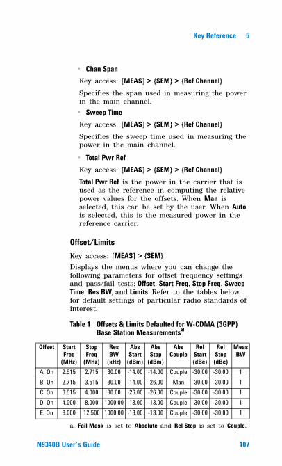
Key Reference 5
� Chan SpanKey access: [MEAS] > {SEM} > {Ref Channel}Specifies the span used in measuring the power in the main channel.
� Sweep TimeKey access: [MEAS] > {SEM} > {Ref Channel}Specifies the sweep time used in measuring the power in the main channel.
� Total Pwr RefKey access: [MEAS] > {SEM} > {Ref Channel}Total Pwr Ref is the power in the carrier that is used as the reference in computing the relative power values for the offsets. When Man is selected, this can be set by the user. When Auto is selected, this is the measured power in the reference carrier.
Offset/LimitsKey access: [MEAS] > {SEM} Displays the menus where you can change the following parameters for offset frequency settings and pass/fail tests: Offset, Start Freq, Stop Freq, Sweep Time, Res BW, and Limits. Refer to the tables below for default settings of particular radio standards of interest.
Table 1 Offsets & Limits Defaulted for W-CDMA (3GPP) Base Station Measurementsa
a. Fail Mask is set to Absolute and Rel Stop is set to Couple.
Offset Start Freq
(MHz)
Stop Freq
(MHz)
Res BW
(kHz)
Abs Start
(dBm)
Abs Stop
(dBm)
Abs Couple
Rel Start (dBc)
Rel Stop (dBc)
Meas BW
A. On 2.515 2.715 30.00 -14.00 -14.00 Couple -30.00 -30.00 1B. On 2.715 3.515 30.00 -14.00 -26.00 Man -30.00 -30.00 1C. On 3.515 4.000 30.00 -26.00 -26.00 Couple -30.00 -30.00 1D. On 4.000 8.000 1000.00 -13.00 -13.00 Couple -30.00 -30.00 1E. On 8.000 12.500 1000.00 -13.00 -13.00 Couple -30.00 -30.00 1
N9340B User�s Guide 107
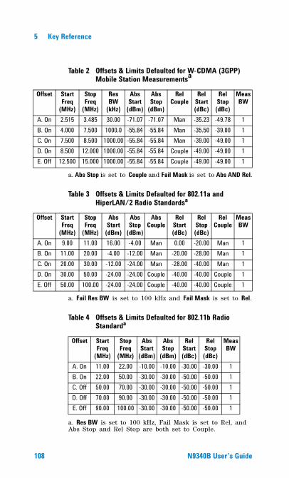
5 Key Reference
Table 2 Offsets & Limits Defaulted for W-CDMA (3GPP) Mobile Station Measurementsa
a. Abs Stop is set to Couple and Fail Mask is set to Abs AND Rel.
Table 3 Offsets & Limits Defaulted for 802.11a and HiperLAN/2 Radio Standardsa
a. Fail Res BW is set to 100 kHz and Fail Mask is set to Rel.
Table 4 Offsets & Limits Defaulted for 802.11b Radio Standarda
a. Res BW is set to 100 kHz, Fail Mask is set to Rel, and Abs Stop and Rel Stop are both set to Couple.
Offset Start Freq
(MHz)
Stop Freq
(MHz)
Res BW
(kHz)
Abs Start
(dBm)
Abs Stop
(dBm)
Rel Couple
Rel Start (dBc)
Rel Stop (dBc)
Meas BW
A. On 2.515 3.485 30.00 -71.07 -71.07 Man -35.23 -49.78 1B. On 4.000 7.500 1000.0 -55.84 -55.84 Man -35.50 -39.00 1C. On 7.500 8.500 1000.00 -55.84 -55.84 Man -39.00 -49.00 1D. On 8.500 12.000 1000.00 -55.84 -55.84 Couple -49.00 -49.00 1E. Off 12.500 15.000 1000.00 -55.84 -55.84 Couple -49.00 -49.00 1
Offset Start Freq
(MHz)
Stop Freq
(MHz)
Abs Start
(dBm)
Abs Stop
(dBm)
Abs Couple
Rel Start(dBc)
Rel Stop(dBc)
Rel Couple
Meas BW
A. On 9.00 11.00 16.00 -4.00 Man 0.00 -20.00 Man 1B. On 11.00 20.00 -4.00 -12.00 Man -20.00 -28.00 Man 1C. On 20.00 30.00 -12.00 -24.00 Man -28.00 -40.00 Man 1D. On 30.00 50.00 -24.00 -24.00 Couple -40.00 -40.00 Couple 1E. Off 50.00 100.00 -24.00 -24.00 Couple -40.00 -40.00 Couple 1
Offset Start Freq
(MHz)
Stop Freq
(MHz)
Abs Start
(dBm)
Abs Stop
(dBm)
Rel Start(dBc)
Rel Stop(dBc)
Meas BW
A. On 11.00 22.00 -10.00 -10.00 -30.00 -30.00 1B. On 22.00 50.00 -30.00 -30.00 -50.00 -50.00 1C. Off 50.00 70.00 -30.00 -30.00 -50.00 -50.00 1D. Off 70.00 90.00 -30.00 -30.00 -50.00 -50.00 1E. Off 90.00 100.00 -30.00 -30.00 -50.00 -50.00 1
108 N9340B User�s Guide
Key Reference 5
OffsetKey access: [MEAS] > {SEM} > {Offset/Limits}Selects the offset pairs (upper and lower) that the softkeys affect, and displays the memory selection menu from A to E (where you can store up to 5 sets of values for Start Freq, Stop Freq, Sweep Time, Res BW, Meas BW, Abs Start, Abs Stop, and so forth). Press Offset until the letter of the desired offset (A, B, C, D, or E) is underlined. Only one selection at a time is shown on this key label.
Start FreqKey access: [MEAS] > {SEM} > {Offset/Limits}Specifies the inner limit (frequency closest to the carrier) for both segments of the specified offset pair. When Start Freq (Off) is selected, the offset pair is not measured.
Stop FreqKey access: [MEAS] > {SEM} > {Offset/Limits}Specifies the outer limit (frequency furthest from the carrier) for both segments of the specified offset pair. The minimum frequency difference between Start Freq and Stop Freq is limited to 100 Hz.
Sweep TimeKey access: [MEAS] > {SEM} > {Offset/Limits}Specifies the sweep time for the currently selected offset, and toggles this function between Auto and Manual for each offset.
Res BWKey access: [MEAS] > {SEM} > {Offset/Limits}Specifies the resolution bandwidth used in measuring the offset pair. When set to Auto, the Res BW from the default tables for “Offset/Limits" on page 107 are used. When set to Man, the allowed range is 1 kHz to 1MHz.
N9340B User�s Guide 109
5 Key Reference
Abs StartAmptKey access: [MEAS] > {SEM} > {Offset/Limits} > {More}Enables you to enter an absolute level limit at Start Freq for the currently selected offset ranging from –200.00 to +50.00 dBm with 0.01 dB resolution.
Abs StopAmptKey access: [MEAS] > {SEM} > {Offset/Limits} > {More}Enters an absolute level limit at Stop Freq for the currently selected offset ranging from –200.00 to +50.00 dBm with 0.01 dB resolution, and to toggle this function between Couple and Man. If set to Couple, this is coupled to Abs Start to make a flat limit line. If set to Man, Abs Start and Abs Stop you can enter different values to make a sloped limit line.
Rel StartAmptKey access: [MEAS] > {SEM} > {Offset/Limits} > {More}Enters a relative level limit at Start Freq ranging from –150.00 to +50.00 dBc with 0.01 dB resolution.
Rel StopAmptKey access: [MEAS] > {SEM} > {Offset/Limits} > {More}Enters a relative level limit at Stop Freq ranging from –150.00 to +50.00 dBc with 0.01 dB resolution, and to toggle this function between Couple and Man. If set to Couple, this is coupled to Rel Start to make a flat limit line. If set to Man, Rel Start and Rel Stop you can enter different values to make a sloped limit line.
110 N9340B User�s Guide
Key Reference 5
Meas BWKey access: [MEAS] > {SEM} > {Offset/Limits} > {More} > {More}Specifies the bandwidth to use when measuring the offset. When using the front panel, only the currently selected offset is affected. All the offsets are affected when remote control. This is the multiplier applied to the resolution bandwidth to determine the bandwidth to integrate when calculating the power. Meas BW is now restricted to be 1 and not changeable.
Fail MaskKey access: [MEAS] > {SEM} > {Offset/Limits} > {More} > {More}Displays the menu to select one of the following logic keys for fail conditions between the measurement results and the test limits:
� AbsoluteSets the limit test to show Fail if one offset is larger than the corresponding limit for Abs Start and/or Abs Stop. This is the default selection for each offset for BTS measurements.
� RelativeSets the limit test to show Fail if one offsets spectrum emission mask measurement results is larger than the corresponding limit for Rel Start and/or Rel Stop.
� Abs AND RelSet the limit test to show fail if one offset’s emission mask measurement results is larger than both the corresponding limit for Abs Start and Stop and the limit for Rel Start and Rel Stop.
� Abs or RelSet the limit test to show fail if one offset’s the absolute emission mask measurement results is larger than the corresponding limit for Abs Start and Stop or the limit for Rel Start and Rel Stop.
N9340B User�s Guide 111
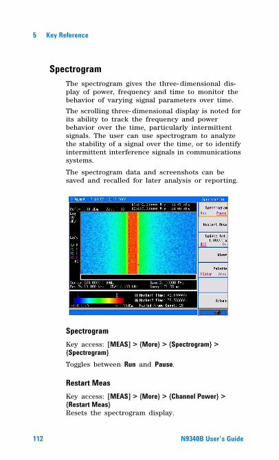
5 Key Reference
SpectrogramThe spectrogram gives the three- dimensional dis-play of power, frequency and time to monitor the behavior of varying signal parameters over time.
The scrolling three- dimensional display is noted for its ability to track the frequency and power behavior over the time, particularly intermittent signals. The user can use spectrogram to analyze the stability of a signal over the time, or to identify intermittent interference signals in communications systems.
The spectrogram data and screenshots can be saved and recalled for later analysis or reporting.
SpectrogramKey access: [MEAS] > {More} > {Spectrogram} > {Spectrogram}Toggles between Run and Pause.
Restart MeasKey access: [MEAS] > {More} > {Channel Power} > {Restart Meas}Resets the spectrogram display.
112 N9340B User�s Guide
Key Reference 5
Update IntervalKey access: [MEAS] > {More} > {Channel Power} > {Update Int.}Enables you to set the interval of time to update data to 1 or more seconds. Or, you may set it to automatically determine the Update Interval that provides the maximum data collection speed.A data sample is taken every time interval for display on the spectrogram. Increasing the update time allows data capturing over a longer period of time in the spectrogram.
Spec ViewKey access: [MEAS] > {More} > {Channel Power}Enables you to page up and down in the captured spectrogram.
PaletteKey access: [MEAS] > {More} > {Channel Power} > {Palette}Toggles the spectrogram color mode between full color and grayscale.
N9340B User�s Guide 113
5 Key Reference
SPAN
Hardkey menu access.
Accesses the softkey submenu of span functions. Pressing [SPAN] allows you to change the frequency range. The frequency- span readout describes the total displayed frequency range. To determine frequency span per horizontal graticule division (when in linear frequency scale type), divide the frequency span by 10.
SpanKey access: [SPAN] > {Span}Enter a frequency span range value.
FullKey access: [SPAN] > {Full}Changes the span to the full frequency range of the analyzer.
ZeroKey access: [SPAN] > {Zero}Changes the frequency span to zero. In this mode, the current center frequency is displayed in the time domain (the x axis is displayed in units of time), like a conventional oscilloscope.
Last SpanKey access: [SPAN] > {Last Span}Changes the span to the previous span setting.
114 N9340B User�s Guide
Key Reference 5
TRACE
Accesses the trace keys to store and manipulate trace information. Each trace comprises a series of data points in which amplitude information is stored. The analyzer updates the data for any active trace with each successive sweep.
TraceKey access: [TRACE] > {Trace}Selects the trace (1- 4) for current use.
Clear WriteKey access: [TRACE] > {Clear Write} Erases any previously stored trace data and continuously updates the display during following sweeps of the analyzer. This function is activated for trace 1 at power on and factory preset.
Max HoldKey access: [TRACE] > {Max Hold}Maintains the diplayed maximum level for each trace point of the selected trace. A trace point is updated if a new maximum level is detected in successive sweeps.
NOTE Changing the vertical scale (Amplitude, Scale Type, Log or Line), or pressing PRESET, or turning averaging on (TRACE, Average (On)) or switching widow in Zone Span restarts the held trace.
N9340B User�s Guide 115
5 Key Reference
Minimum HoldKey access: [TRACE] > {Min Hold}Maintains the minimum level for each trace point of the selected trace, and updates each trace point if a new minimum level is detected in successive sweeps.
ViewKey access: [TRACE] > {View}Holds and displays the amplitude data of the selected trace. The trace register is not updated as the analyzer sweeps. If a trace is deactivated by pressing Blank, the stored trace data can be retrieved by pressing View.
BlankKey access: [TRACE] > { Blank}Stores the amplitude data for the selected trace and removes it from the display. The selected trace register will not be updated as the analyzer sweeps. This function is activated for traces 2, 3 and 4 at power- on and Factory Preset.
DetectorKey access: [TRACE] > {More} > {Detector} Selects a specific detector type, or allows the system to auto select the appropriate detector for a measurement.
NOTE Changing the vertical scale (Amplitude, Scale Type, Log or Line), or pressing PRESET, or turning averaging on (TRACE, Average (On)) or switching widow in Zone Span restarts the held trace.
116 N9340B User�s Guide
Key Reference 5
For every trace point displayed, there is a finite time during which the data for that point is collected. The analyzer has the ability to look at all of the data evaluated during that time and present a single point of trace data based on the detector mode. We call the interval during which data for that trace point is being collected, the “bucket”. Thus a trace is more than a series of single points. It is actually a series of trace “buckets”. The data may be sampled many times within each bucket.
With the detector sets to Auto, Pressing [TRACE] > {More} > {Average} and select On changes the detector. The Auto choice depends on marker, and trace functions, and the trace averaging function. If a marker function or measurement is running, the Auto choice of detector is either Average or Sample. When one of the detectors (such as Average) is manually selected instead of Auto, that detector is used without regard to other analyzer settings.
� AutoSelects peak detector as the default. If a measurement condition arises where a different detector type is better, the system will use the alternate selection.
� NormalSelects the maximum and minimum video signal values alternately. When selecting the normal detector, “N” appears in the upper- left corner.
� AverageMeasures the average value of the amplitude across each trace interval (bucket). When Average is selected, “A” appears on the upper- left corner.
� Pos PeakObtains the maximum video signal between the last display point and the present display point and stores this value in memory. It is used primarily when measuring sinusoidal (spectral) components. When Positive Peak is selected, “P” appears in the upper- left corner.
N9340B User�s Guide 117
5 Key Reference
� SamplePrimarily used to display noise (or noise- like) signals. It should not be used to measure the accurate amplitude of non noise- like signals.
In sample mode, the instantaneous signal value at the present display point is placed in memory. When Sample detector is selected, “S” appears in the upper- left corner of the display.
� Neg PeakSimilar to peak detector, but selects the minimum video signal value. Not to be used to measure the most accurate amplitude. When in Negative Peak mode, an “N” also appears in the upper- left corner.
AverageKey access: [TRACE] > {More} > {Average}Initiates a digital averaging routine that averages the trace points in a number of successive sweeps resulting in trace “smoothing”. Increasing the average number will further smooth the trace. For the information of the type of averaging please refer to “Avg Type" on page 89.
The average is restarted when any of the following occurs:
• A new average number is entered.
• Any related parameter (e.g., center frequency) is changed.
Press Average (Off) to turn off averaging.
The number of sweeps can only be set using the numeric keypad, not the knob or arrow keys.
118 N9340B User�s Guide
Key Reference 5
Save TraceKey access: [TRACE] > {More} > {Save trace}Saves a current trace into a file (*.DAT).
The analyzer uses the filename of the preceding file saved, but adds an integer in 1, 2, 3 sequence to the end of the filename to differentiate it from others.
If there is no record of saved trace in the analyzer, the default file name of the current saved trace will be “HYTRACE.DAT”.
Save AsKey access: [TRACE] > {More} > {Save as}Saves a current trace to a file/directory, with a user- defined filename.
The filename is entered using the numeric keypad and terminated by pressing [ENTER].Numbers, alpha characters and underline are all valid components of a filename.
Recall TraceKey access: [TRACE] > {More} > {Recall trace}The user may recalls a saved trace as the current activated trace.
N9340B User�s Guide 119
5 Key Reference
LIMIT
Limit LineKey access: [Limit] > {Limit Line}Activates an adjustable horizontal line that is used as a visual reference line.
The limit line, used for trace arithmetic, has amplitude values that correspond to its vertical position when compared to the reference level. The value of the display line appears in both the active function block and on the left side of the display. The arrow keys, knob, or numeric keypad may be used to adjust the display line. Pressing any digit, 0 through 9, on the numeric keypad brings up the selected terminator menu. To deactivate the display line, press Display Line (Off).
Limit PatternKey access: [Limit] > {Limit Pattern}Turns on the limit pattern function and turns off the limit line function simultaneously.
Set PatternKey access: [Limit] > {Set Pattern}Allows you to set a limit pattern for measurements.
You can create or edit limit points up to four points to define the limit line.
Pressing X Axis Unite to toggle the frequency domain or time domain before you set the parameter of limit point.
120 N9340B User�s Guide
Key Reference 5
Limit TypeKey access: [Limit] > {Limit Type}Defines the limit you are editing as either an upper or lower limit. An upper limit fails if trace 1 exceeds the limit. A lower limit fails if trace 1 falls below the limit.
BeepKey access: [Limit] > {Beep}Turns the Beep feature on or off. When on, it sounds an alarm as an indicator of a measurement limit failure.
Save PatternKey access: [Limit] > {Save Pattern}Saves the parameters of the current limit pattern in a file (*.PTN).
Enter the user defined filename using the numeric keypad and press [ENTER] as a terminator.
Number, alpha characters and underline are all valid components of a filename.
Recall PatternKey access: [Limit] > {Recall Pattern}Recalls files previously saved containing the limit parameters that may be frequently used for test purposes.
N9340B User�s Guide 121

5 Key Reference
122 N9340B User�s Guide
Agilent N9340B Handheld Spectrum Analyzer
6SCPI Command Reference
This charpter contains basic information on using SCPI commands to control the analyzer.
123Agilent Technologies
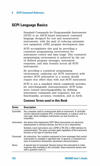
6 SCPI Command Reference
SCPI Language Basics
Standard Commands for Programmable Instruments (SCPI) is an ASCII- based instrument command language designed for test and measurement instruments, with the goal of reducing automatic test equipment (ATE) program development time.
SCPI accomplishes this goal by providing a consistent programming environment for instrument control and data usage. This consistent programming environment is achieved by the use of defined program messages, instrument responses, and data formats across all SCPI instruments.
By providing a consistent programming environment, replacing one SCPI instrument with another SCPI instrument in a system should require less effort than with non- SCPI instrument.
SCPI is not a standard which completely provides for interchangeable instrumentation. SCPI helps move toward interchangeability by defining instrument commands and responses, but not functionality, accuracy, resolution, and so forth.
Common Terms used in this Book
Terms DescriptionController: Any computer used to communicate with an instrument. A controller
can be a personal computer (PC), a minicomputer, or a plug-in card in a card cage. Some intelligent instruments can also function as controllers.
Instrument: Any device that implements SCPI. Most instruments are electronic measurement or stimulus devices, but this is not a requirement.Similarly, most instruments use a GPIB or RS-232 or USB interface for communication. The same concepts apply regardless of the instrument function or the type of interface used.
Command: An instruction. You combine commands to form messages that control instruments to complete a specified task. In general, a command con-sists of mnemonics (keywords), parameters and punctuation.
Query: A special type of command. Queries instruct the instrument to make response data available to the controller. Query keywords always end with a question mark (?).
124 N9340B User�s Guide
SCPI Command Reference 6
Basic Knowledge RequirementProgramming with SCPI requires knowledge of:
• Computer programming languages, such as C or C++.
• The language of your instrument. A N9340B employs SCPI as its programming language.
Command CategoriesSCPI command falls into two categories:
• Subsystem commands
• Common commands
Use a computer to control the signal generator (but operate the line power switch manually). Computer programming procedures for the spectrum analyzer involve selecting a programming statement and then adding the specified programming codes to that statement to achieve the desired operating conditions.
Command SyntaxCommand syntax includes standard notations and statement rules.
Command Statement Rules Overview• Command statements read from left to right
• Use either long form or short form of keywords, but do not use both
• No separating space between the keywords, only use a colon to separate keywords of different levels
• Always separating a keyword from a variable with a space
• Always separating a variable from its unit with a space (if variable has a unit)
N9340B User�s Guide 125
6 SCPI Command Reference
Standard NotationsA command consists of mnemonics (keywords), parameters and punctuation. Before you start to program your analyzer, familiarize yourself with the standard notation of each of them.
KeywordsMany commands have both a long and a short form: use either one. (a combination of the two is not allowed). Consider the:FREQuency command for example:
• Short form :FREQ
• Long form :FREQuency
SCPI is not case sensitive, so fREquEncy is just as valid as FREQUENCY, but FREQ and FREQUENCY are the only valid forms of the FREQuency command.
In this documentation, upper case letters indicate the short form of the keyword. The upper case and lower case letters indicate the long form of the keyword.
Punctuation• A vertical bar "|" dictates a choice of one ele-
ment from a list. For example: <A>|<B> indicates that either A or B can be selected, but not both.
• Square brackets "[ ]" indicates that the enclosed items are optional.
• Angle brackets "< >" indicates a variable value to be defined.
• A question mark "?" after a command indicates that this command is a query. The instrument should return a data to the controller.
• A curly brackets “{ }” indicates a variable parameters to be defined.
126 N9340B User�s Guide
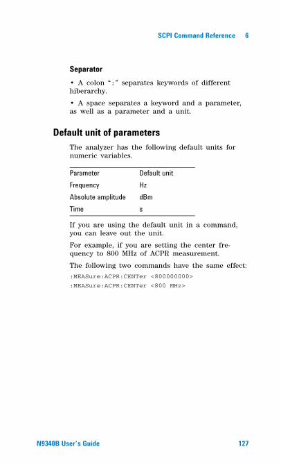
SCPI Command Reference 6
Separator• A colon “:” separates keywords of different hiberarchy.
• A space separates a keyword and a parameter, as well as a parameter and a unit.
Default unit of parametersThe analyzer has the following default units for numeric variables.
If you are using the default unit in a command, you can leave out the unit.
For example, if you are setting the center fre-quency to 800 MHz of ACPR measurement.
The following two commands have the same effect::MEASure:ACPR:CENTer <800000000>
:MEASure:ACPR:CENTer <800 MHz>
Parameter Default unitFrequency HzAbsolute amplitude dBmTime s
N9340B User�s Guide 127
6 SCPI Command Reference
Common Commands
These commands are specified in IEEE Standard 488.2- 1992, IEEE Standard Codes, Formats, Protocols and Common Commands for Use with ANSI/IEEE Std 488.1- 1987. New York, NY, 1992.
Clear Status*CLS
This command clears the error queue of the analyzer.
Standard Event Status Enable*ESE <number>*ESE?
Sets the bits in the standard event status enable register. This register monitors I/O errors and synchronization conditions such as operation complete, request control, query error, device dependent error, execution error, command error and power on. A summary bit is generated on execution of the command.
Query returns the state of the standard event status enable register.
Range:. Integer, 0 to 255
Standard Event Status Register Query*ESR?
Queries and clears the standard event status event register. (This is a destructive read.)
Range: Integer, 0 to 255
128 N9340B User�s Guide
SCPI Command Reference 6
Identification Query*IDN?
This command returns an instrument identification information string. The response is organized into four fields by commas. The field definitions are as follows:
• Manufacturer
• Model
• Serial number
• Firmware version
Operation Complete*OPC*OPC?
Sets bit 0 in the standard event status register to “1” when all pending operations have finished.
The query stops any new commands from being processed until the current processing is complete. Then it returns a “1”, and the program continues. This query can be used to synchronize events of other instruments on the external bus.
*OPC and *OPC? are currently effective only when immediately preceded by the :INITiate:IMMediate command.
Reset*RST
This command returns the instrument to a factory defined condition that is appropriate for remote programming operation.
N9340B User�s Guide 129
6 SCPI Command Reference
Service Request Enable*SRE <integer>*SRE?
This command sets the value of the service request enable register.
The query returns the value of the register.
Range: Integer, 0 to 255
Read Status Byte Query*STB?
Returns the value of the status byte register with-out erasing its contents.
Self Test Query*TST?
This query is used for a self test.
Wait-to-Continue*WAI
This command causes the instrument to wait until all pending commands are completed before exe-cuting any additional commands. There is no query form to the command.
130 N9340B User�s Guide
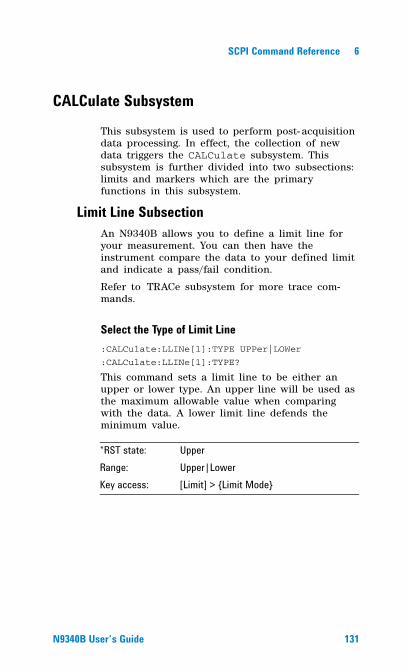
SCPI Command Reference 6
CALCulate Subsystem
This subsystem is used to perform post- acquisition data processing. In effect, the collection of new data triggers the CALCulate subsystem. This subsystem is further divided into two subsections: limits and markers which are the primary functions in this subsystem.
Limit Line SubsectionAn N9340B allows you to define a limit line for your measurement. You can then have the instrument compare the data to your defined limit and indicate a pass/fail condition.
Refer to TRACe subsystem for more trace com-mands.
Select the Type of Limit Line:CALCulate:LLINe[1]:TYPE UPPer|LOWer
:CALCulate:LLINe[1]:TYPE?
This command sets a limit line to be either an upper or lower type. An upper line will be used as the maximum allowable value when comparing with the data. A lower limit line defends the minimum value.
*RST state: UpperRange: Upper|LowerKey access: [Limit] > {Limit Mode}
N9340B User�s Guide 131
6 SCPI Command Reference
Control Limit line Buzzer:CALCulate:LLINe[1]:BUZZer[:STATe] OFF|ON|0|1
:CALCulate:LLINe[1]:BUZZer[:STATe]?
This command toggles the audio warning between on and off. If data exceeds the limit line the buzzer will sound an alarm.
Control Limit Line Testing:CALCulate:LLINe[1]:[STATe] OFF|ON|0|1
:CALCulate:LLINe[1]:[STATe]?
This command toggles the limit line testing between on and off.
If the limit line is turned on, limit pattern is automatically turned off.
Set Limit Line Y-axis value:CALCulate:LLINe[1]:Y <value>
:CALCulate:LLINe[1]:Y?
This command sets the Y- axis value of a limit line.
Limit line Y- axis value is set independently and is not affected by the X- axis units.
*RST state: OffKey access: [Limit] > {Beep}
*RST state: OffKey access: [Limit] > {Limit Line}
*RST value: 0 dBmAvailable unit: dBm, -dBm, mV, uVKey access: [Limit] > {Limit Line}
132 N9340B User�s Guide
SCPI Command Reference 6
Control Limit Pattern Testing:CALCulate:LLINe[1]:PATTern[:STATe] OFF|ON|0|1
:CALCulate:LLINe[1]:PATTern[:STATe]?
This command toggles the usage of limit pattern between on and off.
If the limit pattern is turned on, limit line is automatically turned off.
Set Limit Pattern X-axis Units:CALCulate:LLINe[1]:PATTern:DOMain FREQ|TIME
:CALCulate:LLINe[1]:PATtern:DOMain?
This command selects how the limit pattern points are defined: according to the frequency or sweep time setting of the spectrum analyzer. The query command returns a string of FREQ or TIME.
Define Limit Pattern Values:CALCulate:LLINe[1]:DATA <x-axis>,<ampl>{,<x-axis>,<ampl>}
:CALCulate:LLINe[1]:DATA?
This command defines limit pattern values, and destroys all existing data. A N9340B allows you to set as many as four points to compose the limit pattern by connecting them together.
<x- axis> can be a frequency or time axis.
*RST state: OffKey access: [Limit] > {Limit Pattern}
*RST state: FrequencyRange: FREQ|TIMEKey access: [Limit] > {Set pattern} > {X axis unit}
*RST state: OffKey access: [Limit] > {Set Pattern}
N9340B User�s Guide 133
6 SCPI Command Reference
• <x-axis> – are variables in frequency or time domain as specified by :CALCulate:LLINe[1]:PATTern:DOMain
FREQ|TIME.
• <ampl> – amplitude values are in the current Y- axis units.
CALCulate:MARKer Subsection
Markers All Off on All Traces:CALCulate:MARKer:AOFF
This command turns off all markers on all traces.
Markers All On :CALCulate:MARKer:ALL
This command turns on all the markers and places them on six highest peaks.
Domain Valid unitFrequency Hz, kHz, MHz, GHzTime ms, ms, s, ks
Key access: [Marker] > {More} > {All Off}
*RST state: OffKey access: [Marker] > {Peak search} > {Auto search}
134 N9340B User�s Guide
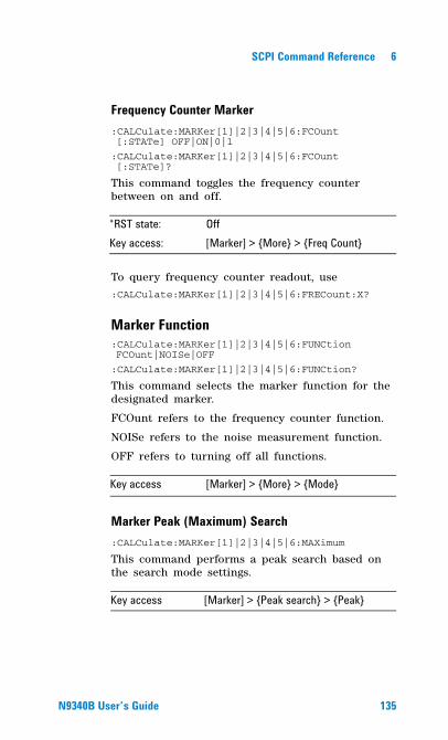
SCPI Command Reference 6
Frequency Counter Marker:CALCulate:MARKer[1]|2|3|4|5|6:FCOunt [:STATe] OFF|ON|0|1
:CALCulate:MARKer[1]|2|3|4|5|6:FCOunt [:STATe]?
This command toggles the frequency counter between on and off.
To query frequency counter readout, use:CALCulate:MARKer[1]|2|3|4|5|6:FRECount:X?
Marker Function:CALCulate:MARKer[1]|2|3|4|5|6:FUNCtion FCOunt|NOISe|OFF
:CALCulate:MARKer[1]|2|3|4|5|6:FUNCtion?
This command selects the marker function for the designated marker.
FCOunt refers to the frequency counter function.
NOISe refers to the noise measurement function.
OFF refers to turning off all functions.
Marker Peak (Maximum) Search:CALCulate:MARKer[1]|2|3|4|5|6:MAXimum
This command performs a peak search based on the search mode settings.
*RST state: OffKey access: [Marker] > {More} > {Freq Count}
Key access [Marker] > {More} > {Mode}
Key access [Marker] > {Peak search} > {Peak}
N9340B User�s Guide 135
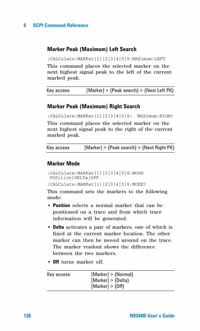
6 SCPI Command Reference
Marker Peak (Maximum) Left Search:CALCulate:MARKer[1]|2|3|4|5|6:MAXimum:LEFT
This command places the selected marker on the next highest signal peak to the left of the current marked peak.
Marker Peak (Maximum) Right Search:CALCulate:MARKer[1]|2|3|4|5|6: MAXimum:RIGHt
This command places the selected marker on the next highest signal peak to the right of the current marked peak.
Marker Mode:CALCulate:MARKer[1]|2|3|4|5|6:MODE POSition|DELTa|OFF
:CALCulate:MARKer[1]|2|3|4|5|6:MODE?
This command sets the markers to the following mode:
• Position selects a normal marker that can be positioned on a trace and from which trace information will be generated.
• Delta activates a pair of markers, one of which is fixed at the current marker location. The other marker can then be moved around on the trace. The marker readout shows the difference between the two markers.
• Off turns marker off.
Key access [Marker] > {Peak search} > {Next Left PK}
Key access [Marker] > {Peak search} > {Next Right PK}
Key access: [Marker] > {Normal} [Marker] > {Delta} [Marker] > {Off}
136 N9340B User�s Guide
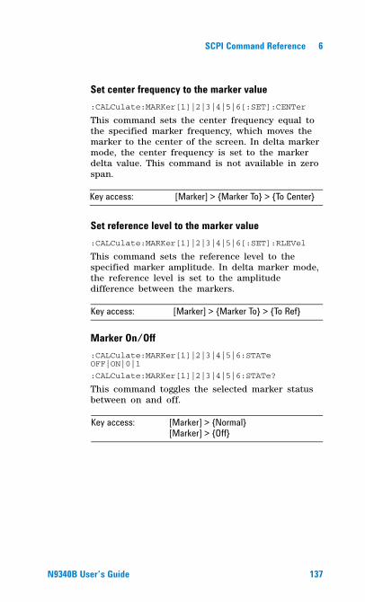
SCPI Command Reference 6
Set center frequency to the marker value:CALCulate:MARKer[1]|2|3|4|5|6[:SET]:CENTer
This command sets the center frequency equal to the specified marker frequency, which moves the marker to the center of the screen. In delta marker mode, the center frequency is set to the marker delta value. This command is not available in zero span.
Set reference level to the marker value:CALCulate:MARKer[1]|2|3|4|5|6[:SET]:RLEVel
This command sets the reference level to the specified marker amplitude. In delta marker mode, the reference level is set to the amplitude difference between the markers.
Marker On/Off:CALCulate:MARKer[1]|2|3|4|5|6:STATe OFF|ON|0|1
:CALCulate:MARKer[1]|2|3|4|5|6:STATe?
This command toggles the selected marker status between on and off.
Key access: [Marker] > {Marker To} > {To Center}
Key access: [Marker] > {Marker To} > {To Ref}
Key access: [Marker] > {Normal} [Marker] > {Off}
N9340B User�s Guide 137
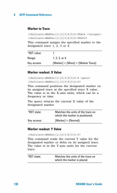
6 SCPI Command Reference
Marker to Trace:CALCulate:MARKer[1]|2|3|4|5|6:TRACe <integer>
:CALCulate:MARKer[1]|2|3|4|5|6:TRACe?
This command assigns the specified marker to the designated trace 1, 2, 3 or 4.
Marker readout: X Value:CALCulate:MARKer[1]|2|3|4|5|6:X <para>
:CALCulate:MARKer[1]|2|3|4|5|6:X?
This command positions the designated marker on its assigned trace at the specified trace X value. The value is in the X- axis units, which can be a frequency or time.
The query returns the current X value of the designated marker.
Marker readout: Y Value:CALCulate:MARKer[1]|2|3|4|5|6:Y?
This command reads the current Y value for the designated marker or delta on its assigned trace. The value is in the Y- axis units for the current trace.
*RST value: 1Range: 1, 2, 3, or 4Key access: [Marker] > {More} > {Marker Trace}
*RST state: Matches the units of the trace on which the marker is positioned.
Key access: [Marker] > {Normal}
*RST state: Matches the units of the trace on which the marker is placed.
138 N9340B User�s Guide
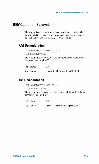
SCPI Command Reference 6
DEMOdulation Subsystem
This sub tree commands are used to control the demodulation after the measure has been loaded by[:SENSe]:FREQuency:SPAN:ZERO
AM Demodulation:DEMod:AM:STATe OFF|ON|0|1
:DEMod:AM:STATe?
This command toggles AM demodulation function between on and off.
FM Demodulation:DEMod:FM:STATe OFF|ON|0|1
:DEMod:FM:STATe?
This command toggles FM demodulation function between on and off.
*RST state: OffKey access: [Span] > {Demode} > {AM (On)}
*RST state: Off
Key access: [SPAN] > {Demode} > {FM (On)}
N9340B User�s Guide 139
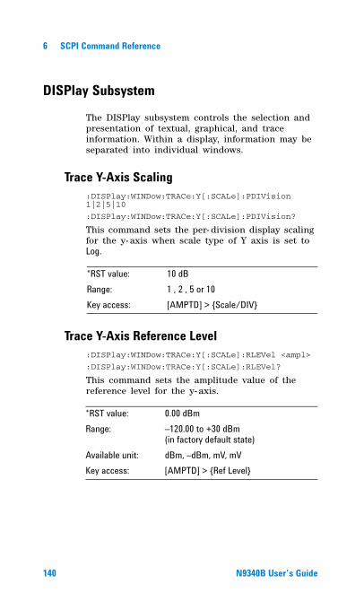
6 SCPI Command Reference
DISPlay Subsystem
The DISPlay subsystem controls the selection and presentation of textual, graphical, and trace information. Within a display, information may be separated into individual windows.
Trace Y-Axis Scaling:DISPlay:WINDow:TRACe:Y[:SCALe]:PDIVision 1|2|5|10
:DISPlay:WINDow:TRACe:Y[:SCALe]:PDIVision?
This command sets the per- division display scaling for the y- axis when scale type of Y axis is set to Log.
Trace Y-Axis Reference Level:DISPlay:WINDow:TRACe:Y[:SCALe]:RLEVel <ampl>
:DISPlay:WINDow:TRACe:Y[:SCALe]:RLEVel?
This command sets the amplitude value of the reference level for the y- axis.
*RST value: 10 dBRange: 1 , 2 , 5 or 10Key access: [AMPTD] > {Scale/DIV}
*RST value: 0.00 dBmRange: �120.00 to +30 dBm
(in factory default state)Available unit: dBm, �dBm, mV, mVKey access: [AMPTD] > {Ref Level}
140 N9340B User�s Guide
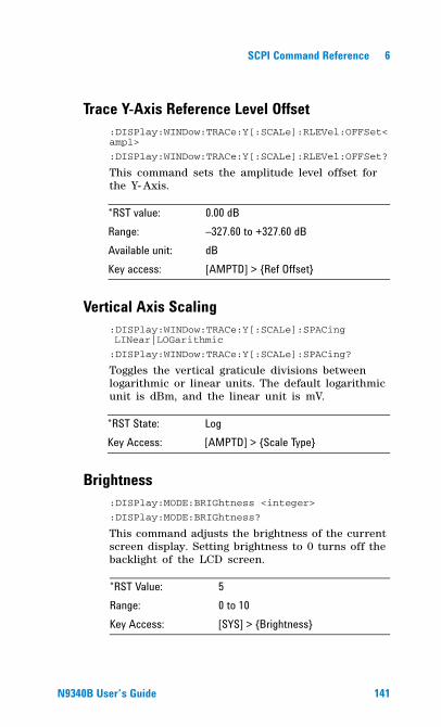
SCPI Command Reference 6
Trace Y-Axis Reference Level Offset:DISPlay:WINDow:TRACe:Y[:SCALe]:RLEVel:OFFSet<ampl>
:DISPlay:WINDow:TRACe:Y[:SCALe]:RLEVel:OFFSet?
This command sets the amplitude level offset for the Y- Axis.
Vertical Axis Scaling:DISPlay:WINDow:TRACe:Y[:SCALe]:SPACing LINear|LOGarithmic
:DISPlay:WINDow:TRACe:Y[:SCALe]:SPACing?
Toggles the vertical graticule divisions between logarithmic or linear units. The default logarithmic unit is dBm, and the linear unit is mV.
Brightness:DISPlay:MODE:BRIGhtness <integer>
:DISPlay:MODE:BRIGhtness?
This command adjusts the brightness of the current screen display. Setting brightness to 0 turns off the backlight of the LCD screen.
*RST value: 0.00 dBRange: �327.60 to +327.60 dBAvailable unit: dBKey access: [AMPTD] > {Ref Offset}
*RST State: LogKey Access: [AMPTD] > {Scale Type}
*RST Value: 5Range: 0 to 10Key Access: [SYS] > {Brightness}
N9340B User�s Guide 141
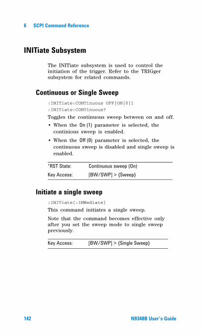
6 SCPI Command Reference
INITiate Subsystem
The INITiate subsystem is used to control the initiation of the trigger. Refer to the TRIGger subsystem for related commands.
Continuous or Single Sweep:INITiate:CONTinuous OFF|ON|0|1
:INITiate:CONTinuous?
Toggles the continuous sweep between on and off.
• When the On (1) parameter is selected, the continious sweep is enabled.
• When the Off (0) parameter is selected, the continuous sweep is disabled and single sweep is enabled.
Initiate a single sweep:INITiate[:IMMediate]
This command initiates a single sweep.
Note that the command becomes effective only after you set the sweep mode to single sweep previously.
*RST State: Continuous sweep (On)Key Access: [BW/SWP] > {Sweep}
Key Access: [BW/SWP] > {Single Sweep}
142 N9340B User�s Guide
SCPI Command Reference 6
INSTrument Subsystem
This subsystem includes commands for querying and selecting instrument measurement mode.
Select One button measurement:INSTrument:MEASure OFF|CHPower|ACPR|OBW|CHP|SEM|FS|
:INSTrument:MEASure?
Selects the one- button measurement among channel power, adjacent channel power ratio, occupied bandwidth, spectrum emission mask and field strength.
Use this command to select a power measurement firstly, then use other commands to set the parameters of this power measurement.
*RST State: OffKey Access: [MEAS]
N9340B User�s Guide 143
6 SCPI Command Reference
MEASure Subsystem
Provides programming information for the keys associated with the measurements available when you press the front- panel Measure key.
OBW Subsection
Selecting the OBW method:MEASure:OBW:METHod PERCent|XDB:MEASure:OBW:METHod?
Sets the method of OBW measurement as percent or xdB.
Setting Percentage (%) method of OBW:MEASure:OBW:PERCent <para>
:MEASure:OBW:PERCent?
Edits the percentage of signal power used when determining the occupied bandwidth. The percentage ranges from 10.00% to 99.99%.
Setting dBc method of OBW:MEASure:OBW:XDB <para>:MEASure:OBW:XDB?
Specifies the power level used to determine the emission bandwidth as the number of dB down from the highest signal point, within the occupied bandwidth span.
Return the measurement result:MEASure:OBW?
Returns the x dB and percent value in OBW.
NOTE This sub tree command must be used after the measure has been loaded by :INSTrument:MEASure ACPR|OBW|CHP|SEM|FS
144 N9340B User�s Guide
SCPI Command Reference 6
ACPR Subsection
Center freq:MEASure:ACPR:CENTer <freq>
:MEASure:ACPR:CENTer?
Sets the center frequency of the main channel power.
Main channel:MEASure:ACPR:MAIN <freq>
:MEASure:ACPR:MAIN?
Specifies the range of integration used in calculating the power in the main channel.
Adjacent channel:MEASure:ACPR:ADJacent <freq>
:MEASure:ACPR:ADJacent?
Specifies the range of integration used in calculating the power in the adjacent channel.
Channel space:MEASure:ACPR:SPACe <freq>
:MEASure:ACPR:SPACe?
Sets the space value between the center frequency of main channel power and that of the adjacent channel power.
Main Channel Power:MEASure:ACPR:MPOWer?
Return the main channel power of ACPR measurement.
N9340B User�s Guide 145
6 SCPI Command Reference
Low Adjacent Channel Power:MEASure:ACPR:LPOWer?
Return the lower adjacent channel power of ACPR measurement.
Upper Adjacent Channel Power:MEASure:ACPR:UPOWer?
Return the upper adjacent channel power of ACPR measurement.
Low Adjacent Channel Power Ratio:MEASure:ACPR:LRATio?
Return the lower adjacent channel power to main channel power ratio.
Upper Adjacent Channel Power Ratio:MEASure:ACPR:URATio?
Return the upper adjacent channel power to main channel power ratio.
146 N9340B User�s Guide
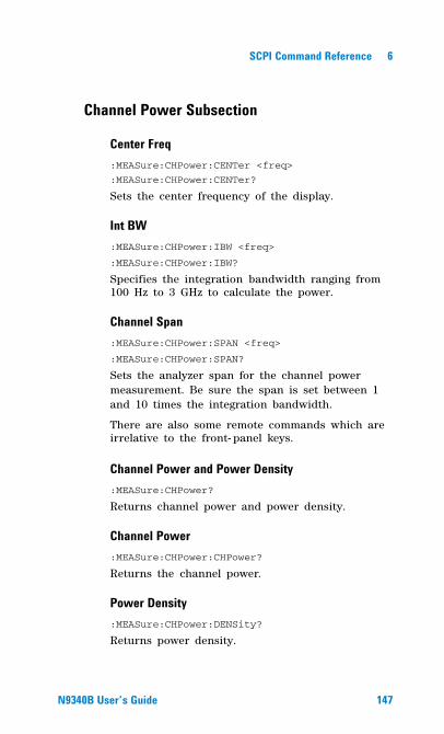
SCPI Command Reference 6
Channel Power Subsection
Center Freq:MEASure:CHPower:CENTer <freq>
:MEASure:CHPower:CENTer?
Sets the center frequency of the display.
Int BW:MEASure:CHPower:IBW <freq>
:MEASure:CHPower:IBW?
Specifies the integration bandwidth ranging from 100 Hz to 3 GHz to calculate the power.
Channel Span:MEASure:CHPower:SPAN <freq>
:MEASure:CHPower:SPAN?
Sets the analyzer span for the channel power measurement. Be sure the span is set between 1 and 10 times the integration bandwidth.
There are also some remote commands which are irrelative to the front- panel keys.
Channel Power and Power Density:MEASure:CHPower?
Returns channel power and power density.
Channel Power:MEASure:CHPower:CHPower?
Returns the channel power.
Power Density:MEASure:CHPower:DENSity?
Returns power density.
N9340B User�s Guide 147
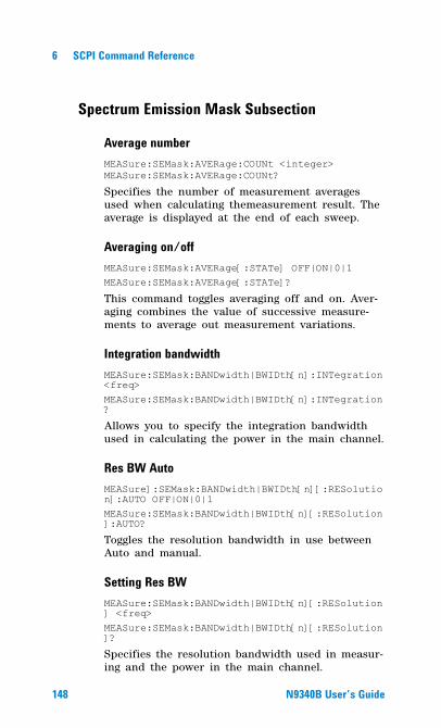
6 SCPI Command Reference
Spectrum Emission Mask Subsection
Average numberMEASure:SEMask:AVERage:COUNt <integer>MEASure:SEMask:AVERage:COUNt?
Specifies the number of measurement averages used when calculating themeasurement result. The average is displayed at the end of each sweep.
Averaging on/offMEASure:SEMask:AVERage[:STATe] OFF|ON|0|1 MEASure:SEMask:AVERage[:STATe]?
This command toggles averaging off and on. Aver-aging combines the value of successive measure-ments to average out measurement variations.
Integration bandwidthMEASure:SEMask:BANDwidth|BWIDth[n]:INTegration <freq>MEASure:SEMask:BANDwidth|BWIDth[n]:INTegration?
Allows you to specify the integration bandwidth used in calculating the power in the main channel.
Res BW AutoMEASure]:SEMask:BANDwidth|BWIDth[n][:RESolution]:AUTO OFF|ON|0|1 MEASure:SEMask:BANDwidth|BWIDth[n][:RESolution]:AUTO?
Toggles the resolution bandwidth in use between Auto and manual.
Setting Res BWMEASure:SEMask:BANDwidth|BWIDth[n][:RESolution] <freq> MEASure:SEMask:BANDwidth|BWIDth[n][:RESolution]?
Specifies the resolution bandwidth used in measur-ing and the power in the main channel.
148 N9340B User�s Guide
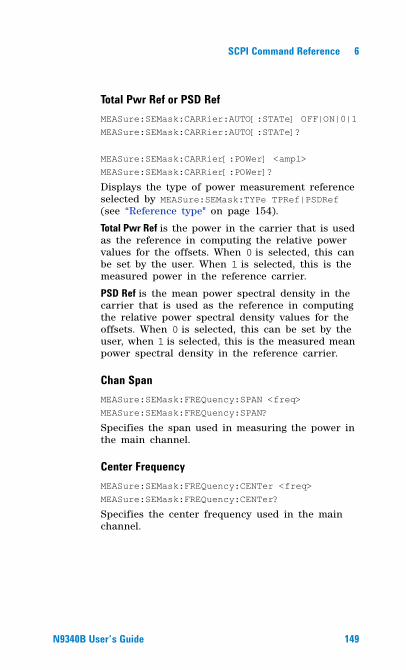
SCPI Command Reference 6
Total Pwr Ref or PSD RefMEASure:SEMask:CARRier:AUTO[:STATe] OFF|ON|0|1MEASure:SEMask:CARRier:AUTO[:STATe]?
MEASure:SEMask:CARRier[:POWer] <ampl> MEASure:SEMask:CARRier[:POWer]?
Displays the type of power measurement reference selected by MEASure:SEMask:TYPe TPRef|PSDRef (see “Reference type" on page 154).
Total Pwr Ref is the power in the carrier that is used as the reference in computing the relative power values for the offsets. When 0 is selected, this can be set by the user. When 1 is selected, this is the measured power in the reference carrier.
PSD Ref is the mean power spectral density in the carrier that is used as the reference in computing the relative power spectral density values for the offsets. When 0 is selected, this can be set by the user, when 1 is selected, this is the measured mean power spectral density in the reference carrier.
Chan SpanMEASure:SEMask:FREQuency:SPAN <freq> MEASure:SEMask:FREQuency:SPAN?
Specifies the span used in measuring the power in the main channel.
Center FrequencyMEASure:SEMask:FREQuency:CENTer <freq>MEASure:SEMask:FREQuency:CENTer?
Specifies the center frequency used in the main channel.
N9340B User�s Guide 149
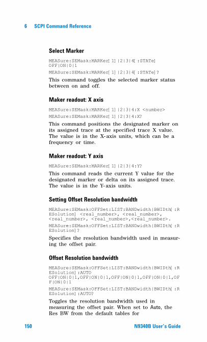
6 SCPI Command Reference
Select MarkerMEASure:SEMask:MARKer[1]|2|3|4[:STATe] OFF|ON|0|1 MEASure:SEMask:MARKer[1]|2|3|4[:STATe]?
This command toggles the selected marker status between on and off.
Maker readout: X axisMEASure:SEMask:MARKer[1]|2|3|4:X <number> MEASure:SEMask:MARKer[1]|2|3|4:X?
This command positions the designated marker on its assigned trace at the specified trace X value. The value is in the X- axis units, which can be a frequency or time.
Maker readout: Y axisMEASure:SEMask:MARKer[1]|2|3|4:Y?
This command reads the current Y value for the designated marker or delta on its assigned trace. The value is in the Y- axis units.
Setting Offset Resolution bandwidthMEASure:SEMask:OFFSet:LIST:BANDwidth|BWIDth[:RESolution] <real_number>, <real_number>, <real_number>, <real_number>,<real_number>. MEASure:SEMask:OFFSet:LIST:BANDwidth|BWIDth[:RESolution]?
Specifies the resolution bandwidth used in measur-ing the offset pair.
Offset Resolution bandwidthMEASure:SEMask:OFFSet:LIST:BANDwidth|BWIDth[:RESolution]:AUTO OFF|ON|0|1,OFF|ON|0|1,OFF|ON|0|1,OFF|ON|0|1,OFF|ON|0|1 MEASure:SEMask:OFFSet:LIST:BANDwidth|BWIDth[:RESolution]:AUTO?
Toggles the resolution bandwidth used in measuring the offset pair. When set to Auto, the Res BW from the default tables for
150 N9340B User�s Guide
SCPI Command Reference 6
“Offset/Limits" on page 107 are used. When set to Man, the range of settings is the range of available Res BWs of the analyzer, except the maximum is further limited to not exceed (Stop Freq - Start Freq).
Setting Meas BWMEASure:SEMask:OFFSet:LIST:BANDwidth|BWIDth:MEASure <Integer>, <Integer>, <Integer>, <Integer>,<Integer>.MEASure:SEMask:OFFSet:LIST:BANDwidth|BWIDth:MEASure?
Enables you to specify the bandwidth to use when measuring the offset. This is the multiplier applied to the resolution bandwidth to determine the bandwidth to integrate when calculating the power.
Setting Start FreqMEASure:SEMask:OFFSet:LIST:FREQuency:STARt <freq>,<freq>,<freq>,<freq>,<freq>MEASure:SEMask:OFFSet:LIST:FREQuency:STARt?
Specifies the inner limit (frequency closest to the carrier) for both segments of the specified offset pair. When Start Freq (Off) is selected, the offset pair is not measured.
Setting Stop FreqMEASure:SEMask:OFFSet:LIST:FREQuency:STOP <freq>,<freq>,<freq>,<freq>,<freq>MEASure:SEMask:OFFSet:LIST:FREQuency:STOP?
Specifies the outer limit (frequency furthest from the carrier) for both segments of the specified off-set pair. The lower range is limited to the setting of Start Freq.
N9340B User�s Guide 151
6 SCPI Command Reference
Turn on/off offsetMEASure:SEMask:OFFSet:LIST:STATe OFF|ON|0|1,OFF|ON|0|1,OFF|ON|0|1,OFF|ON|0|1,OFF|ON|0|1MEASure:SEMask:OFFSet:LIST:STATe?
Turn on/off the offsets for measurement.
Offsets that are turned off, for the currently selected offset will return a - 999.0 when queried.
Offset Sweep TimeMEASure:SEMask:OFFSet:LIST:SWEeptime:AUTO OFF|ON|0|1,OFF|ON|0|1,OFF|ON|0|1,OFF|ON|0|1,OFF|ON|0|1MEASure:SEMask:OFFSet:LIST:SWEeptime:AUTO?
Toggles this function between Auto and Manual for each offset.
Setting Offsets Sweep TimeMEASure:SEMask:OFFSet:LIST:SWEeptime <time>,<time>,<time>,<time>,<time>MEASure:SEMask:OFFSet:LIST:SWEeptime?
Specifies the sweep time for the currently selected offset.
Setting Offset Abs Start MEASure:SEMask:OFFSet:LIST:STARt:ABSolute <ampl>,<ampl>,<ampl>,<ampl>,<ampl>MEASure:SEMask:OFFSet:LIST:STARt:ABSolute?
Enables you to enter an absolute level limit at Start Freq for the currently selected offset.
Setting Offset Rel StartMEASure:SEMask:OFFSet:LIST:STARt:RCARrier <ampl>,<ampl>,<ampl>,<ampl>,<ampl>MEASure:SEMask:OFFSet:LIST:STARt:RCARrier?
Enables you to enter a relative level limit at Start Freq for the currently selected offset.
152 N9340B User�s Guide
SCPI Command Reference 6
Couple Offset Abs StopMEASure:SEMask:OFFSet:LIST:STOP:ABSolute:COUPle OFF|ON|0|1,OFF|ON|0|1,OFF|ON|0|1,OFF|ON|0|1,OFF|ON|0|1MEASure:SEMask:OFFSet:LIST:STOP:ABSolute:COUPle?
toggle this function between Couple and Man. If set to Couple, this is coupled to Abs Start to make a flat limit line. If set to Man, Abs Start and Abs Stop you can enter different values to make a sloped limit line.
Setting Offset Abs StopMEASure:SEMask:OFFSet:LIST:STOP:ABSolute <ampl>,<ampl>,<ampl>,<ampl>,<ampl>MEASure:SEMask:OFFSet:LIST:STOP:ABSolute?
Enables you to enter an absolute level limit at Stop Freq for the currently selected offset.
Couple Offset Rel StopMEASure:SEMask:OFFSet:LIST:STOP:RCARrier:COUPle OFF|ON|0|1,OFF|ON|0|1,OFF|ON|0|1,OFF|ON|0|1,OFF|ON|0|1MEASure:SEMask:OFFSet:LIST:STOP:RCARrier:COUPle?
Toggle this function between Couple and Man. If set to Couple, this is coupled to Rel Start to make a flat limit line. If set to Man, Rel Start and Rel Stop you can enter different values to make a sloped limit line.
Setting Offset Rel StartMEASure:SEMask:OFFSet:LIST:STOP:RCARrier <ampl>,<ampl>,<ampl>,<ampl>,<ampl>MEASure:SEMask:OFFSet:LIST:STOP:RCARrier?
Enables you to enter a relative level limit at Stop Freq for the currently selected offset.
N9340B User�s Guide 153
6 SCPI Command Reference
Fail MaskMEASure:SEMask:OFFSet:LIST:TEST ABSolute|RELative|AND|OR,ABSolute|RELative|AND|OR,ABSolute|RELative|AND|OR,ABSolute|RELative|AND|OR,ABSolute|RELative|AND|OR MEASure:SEMask:OFFSet:LIST:TEST?
Displays the menu to select one of the following logic keys for fail conditions between the measure-ment results and the test limits: Absolute, Relative, Abs AND Rel, and Abs OR Rel.
Sweep Time AutoMEASure:SEMask:SWEeptime:AUTO OFF|ON|0|1MEASure:SEMask:SWEeptime:AUTO?
Toggles the sweep time between auto and manual.
Sweep TimeMEASure:SEMask:SWEeptime <time>MEASure:SEMask:SWEeptime?
Specifies the sweep time used in measuring the power in the main channel.
Reference typeMEASure:SEMask:TYPe TPRef|PSDRefMEASure:SEMask:TYPe?
Selects the measurement reference type as Total Pwr Ref or PSD Ref.
When Total Pwr Ref is selected, the power in the carrier is used as the reference in computing the relative power values for the offsets.
When PSD Ref is selected, the mean power spec-tral density of the carrier is used in computing the relative power spectral density values for the off-sets.
154 N9340B User�s Guide
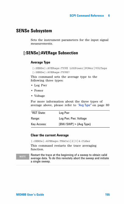
SCPI Command Reference 6
SENSe Subsystem
Sets the instrument parameters for the input signal measurements.
[:SENSe]:AVERage Subsection
Average Type [:SENSe]:AVERage:TYPE LOGPower|POWer|VOLTage
[:SENSe]:AVERage:TYPE?
This command sets the average type to the following three types:
• Log Pwr
• Power
• Voltage
For more information about the three types of average above, please refer to �Avg Type" on page 89
Clear the current Average[:SENSe]:AVERage:TRACe1|2|3|4:CLEar
This command restarts the trace averaging function.
*RST State: Log PwrRange: Log Pwr, Pwr, Voltage
Key Access: [BW/SWP] > {Avg Type}
NOTE Restart the trace at the beginning of a sweep to obtain valid average data. To do this remotely abort the sweep and initiate a single sweep.
N9340B User�s Guide 155
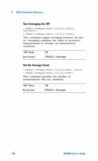
6 SCPI Command Reference
Turn Averaging On/Off[:SENSe]:AVERage:TRACe 1|2|3|4[:STATe] OFF|ON|0|1
[:SENSe]:AVERage:TRACe 1|2|3|4[:STATe]?
This command toggles averaging between off and on. Averaging combines the value of successive measurements to average out measurement variations.
Set the Average Count[:SENSe]:AVERage:TRACe 1|2|3|4:COUNt <value>
[:SENSe]:AVERage:TRACe 1|2|3|4:COUNt?
This command specifies the number of measurements that are combined.
*RST State: Off
Key Access: [TRACE] > {Average}
*RST Value: 100Key Access: [TRACE] > {Average}
156 N9340B User�s Guide
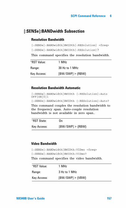
SCPI Command Reference 6
[:SENSe]:BANDwidth Subsection
Resolution Bandwidth[:SENSe]:BANDwidth|BWIDth[:RESolution] <freq>
[:SENSe]:BANDwidth|BWIDth[:RESolution]?
This command specifies the resolution bandwidth.
Resolution Bandwidth Automatic[:SENSe]:BANDwidth|BWIDth [:RESolution]:Auto OFF|ON|0|1
[:SENSe]:BANDwidth|BWIDth [:RESolution]:Auto?
This command couples the resolution bandwidth to the frequency span. Auto- couple resolution bandwidth is not available in zero span..
Video Bandwidth[:SENSe]:BANDwidth|BWIDth:VIDeo <freq>
[:SENSe]:BANDwidth|BWIDth:VIDeo?
This command specifies the video bandwidth.
*RST Value: 1 MHz
Range: 30 Hz to 1 MHzKey Access: [BW/SWP] > {RBW}
*RST State: On
Key Access: [BW/SWP] > {RBW}
*RST Value: 1 MHzRange: 3 Hz to 1 MHzKey Access: [BW/SWP] > {VBW}
N9340B User�s Guide 157
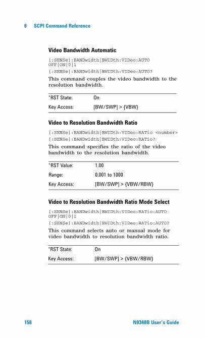
6 SCPI Command Reference
Video Bandwidth Automatic[:SENSe]:BANDwidth|BWIDth:VIDeo:AUTO OFF|ON|0|1
[:SENSe]:BANDwidth|BWIDth:VIDeo:AUTO?
This command couples the video bandwidth to the resolution bandwidth.
Video to Resolution Bandwidth Ratio[:SENSe]:BANDwidth|BWIDth:VIDeo:RATio <number>
[:SENSe]:BANDwidth|BWIDth:VIDeo:RATio?
This command specifies the ratio of the video bandwidth to the resolution bandwidth.
Video to Resolution Bandwidth Ratio Mode Select[:SENSe]:BANDwidth|BWIDth:VIDeo:RATio:AUTO OFF|ON|0|1
[:SENSe]:BANDwidth|BWIDth:VIDeo:RATio:AUTO?
This command selects auto or manual mode for video bandwidth to resolution bandwidth ratio.
*RST State: OnKey Access: [BW/SWP] > {VBW}
*RST Value: 1.00Range: 0.001 to 1000Key Access: [BW/SWP] > {VBW/RBW}
*RST State: OnKey Access: [BW/SWP] > {VBW/RBW}
158 N9340B User�s Guide
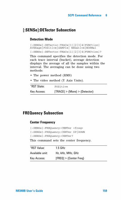
SCPI Command Reference 6
[:SENSe]:DETector Subsection
Detection Mode[:SENSe]:DETector:TRACe[1]|2|3|4[FUNCtion] AVERage|POSitive|SAMPle| NEGative|NORMal
[:SENSe]:DETector:TRACe[1]|2|3|4[FUNCtion]?
This command specifies the detection mode. For each trace interval (bucket), average detection displays the average of all the samples within the interval. The averaging can be done using two methods:
• The power method (RMS)
• The video method (Y Axis Units).
FREQuency Subsection
Center Frequency[:SENSe]:FREQuency:CENTer <freq>
[:SENSe]:FREQuency:CENTer UP|DOWN
[:SENSe]:FREQuency:CENTer?
This command sets the center frequency.
*RST State: POSitive
Key Access: [TRACE] > {More} > {Detector}
*RST Value: 1.5 GHzAvailable unit: Hz, kHz, MHz, GHzKey Access: [FREQ] > {Center Freq}
N9340B User�s Guide 159
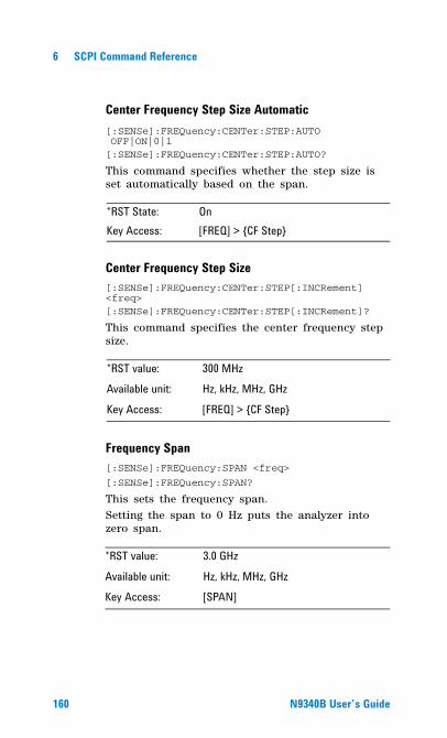
6 SCPI Command Reference
Center Frequency Step Size Automatic[:SENSe]:FREQuency:CENTer:STEP:AUTO OFF|ON|0|1[:SENSe]:FREQuency:CENTer:STEP:AUTO?
This command specifies whether the step size is set automatically based on the span.
Center Frequency Step Size [:SENSe]:FREQuency:CENTer:STEP[:INCRement] <freq>[:SENSe]:FREQuency:CENTer:STEP[:INCRement]?
This command specifies the center frequency step size.
Frequency Span[:SENSe]:FREQuency:SPAN <freq>
[:SENSe]:FREQuency:SPAN?
This sets the frequency span. Setting the span to 0 Hz puts the analyzer into zero span.
*RST State: OnKey Access: [FREQ] > {CF Step}
*RST value: 300 MHzAvailable unit: Hz, kHz, MHz, GHz
Key Access: [FREQ] > {CF Step}
*RST value: 3.0 GHz
Available unit: Hz, kHz, MHz, GHzKey Access: [SPAN]
160 N9340B User�s Guide
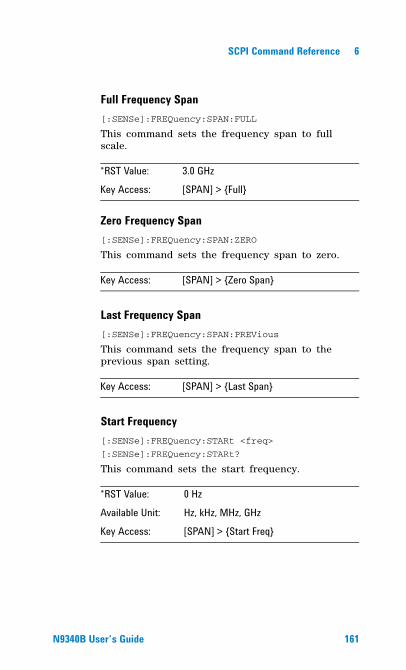
SCPI Command Reference 6
Full Frequency Span[:SENSe]:FREQuency:SPAN:FULL
This command sets the frequency span to full scale.
Zero Frequency Span[:SENSe]:FREQuency:SPAN:ZERO
This command sets the frequency span to zero.
Last Frequency Span[:SENSe]:FREQuency:SPAN:PREVious
This command sets the frequency span to the previous span setting.
Start Frequency[:SENSe]:FREQuency:STARt <freq>
[:SENSe]:FREQuency:STARt?
This command sets the start frequency.
*RST Value: 3.0 GHzKey Access: [SPAN] > {Full}
Key Access: [SPAN] > {Zero Span}
Key Access: [SPAN] > {Last Span}
*RST Value: 0 HzAvailable Unit: Hz, kHz, MHz, GHz
Key Access: [SPAN] > {Start Freq}
N9340B User�s Guide 161
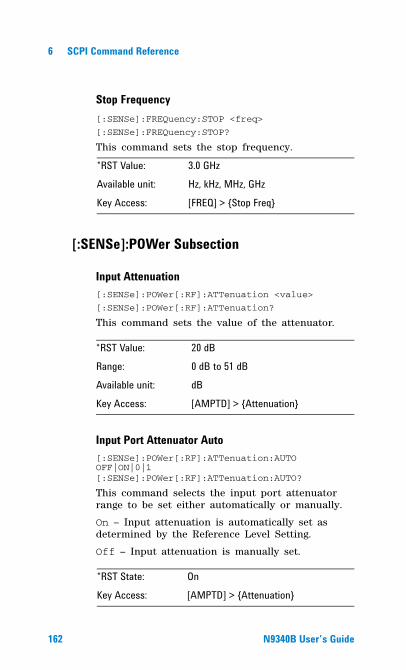
6 SCPI Command Reference
Stop Frequency[:SENSe]:FREQuency:STOP <freq>
[:SENSe]:FREQuency:STOP?
This command sets the stop frequency.
[:SENSe]:POWer Subsection
Input Attenuation[:SENSe]:POWer[:RF]:ATTenuation <value>
[:SENSe]:POWer[:RF]:ATTenuation?
This command sets the value of the attenuator.
Input Port Attenuator Auto[:SENSe]:POWer[:RF]:ATTenuation:AUTO OFF|ON|0|1[:SENSe]:POWer[:RF]:ATTenuation:AUTO?
This command selects the input port attenuator range to be set either automatically or manually.
On – Input attenuation is automatically set as determined by the Reference Level Setting.
Off – Input attenuation is manually set.
*RST Value: 3.0 GHzAvailable unit: Hz, kHz, MHz, GHz
Key Access: [FREQ] > {Stop Freq}
*RST Value: 20 dBRange: 0 dB to 51 dBAvailable unit: dB
Key Access: [AMPTD] > {Attenuation}
*RST State: On
Key Access: [AMPTD] > {Attenuation}
162 N9340B User�s Guide
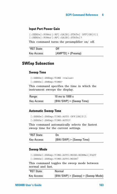
SCPI Command Reference 6
Input Port Power Gain[:SENSe]:POWer[:RF]:GAIN[:STATe] OFF|ON|0|1[:SENSe]:POWer[:RF]:GAIN[:STATe]?
This command turns the preamplifier on/ off.
SWEep Subsection
Sweep Time [:SENSe]:SWEep:TIME <value>
[:SENSe]:SWEep:TIME?
This command specifies the time in which the instrument sweeps the display.
Automatic Sweep Time [:SENSe]:SWEep:TIME:AUTO OFF|ON|0|1
[:SENSe]:SWEep:TIME:AUTO?
This command automatically selects the fastest sweep time for the current settings.
Sweep Mode [:SENSe]:SWEep:TIME:AUTO:MODE:NORMal|FAST
[:SENSe]:SWEep:TIME:AUTO:MODE?
This command toggles the sweep mode between normal and fast.
*RST State: OffKey Access: [AMPTD] > {Preamp}
Range: 10 ms to 1000 sKey Access: [BW/SWP] > {Sweep Time}
*RST State: OnKey Access: [BW/SWP] > {Sweep Time}
*RST State: NormalKey Access: [BW/SWP] > {Sweep} > {Sweep Mode}
N9340B User�s Guide 163
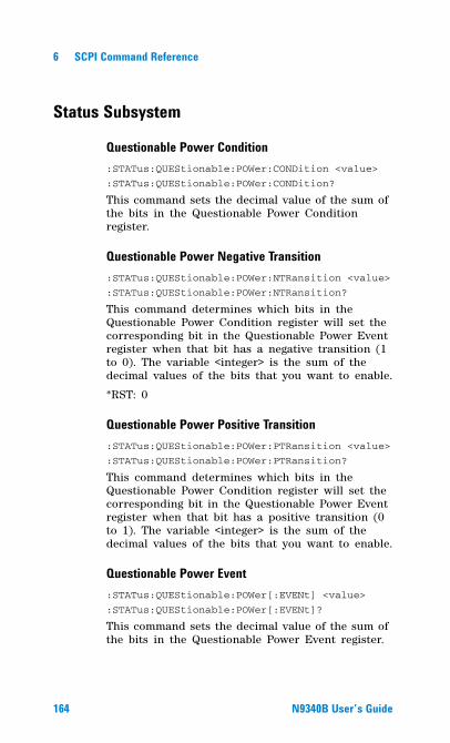
6 SCPI Command Reference
Status Subsystem
Questionable Power Condition:STATus:QUEStionable:POWer:CONDition <value>
:STATus:QUEStionable:POWer:CONDition?
This command sets the decimal value of the sum of the bits in the Questionable Power Condition register.
Questionable Power Negative Transition:STATus:QUEStionable:POWer:NTRansition <value>
:STATus:QUEStionable:POWer:NTRansition?
This command determines which bits in the Questionable Power Condition register will set the corresponding bit in the Questionable Power Event register when that bit has a negative transition (1 to 0). The variable <integer> is the sum of the decimal values of the bits that you want to enable.
*RST: 0
Questionable Power Positive Transition:STATus:QUEStionable:POWer:PTRansition <value>
:STATus:QUEStionable:POWer:PTRansition?
This command determines which bits in the Questionable Power Condition register will set the corresponding bit in the Questionable Power Event register when that bit has a positive transition (0 to 1). The variable <integer> is the sum of the decimal values of the bits that you want to enable.
Questionable Power Event:STATus:QUEStionable:POWer[:EVENt] <value>
:STATus:QUEStionable:POWer[:EVENt]?
This command sets the decimal value of the sum of the bits in the Questionable Power Event register.
164 N9340B User�s Guide
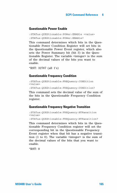
SCPI Command Reference 6
Questionable Power Enable:STATus:QUEStionable:POWer:ENABle <value>
:STATus:QUEStionable:POWer:ENABle?
This command determines which bits in the Ques-tionable Power Condition Register will set bits in the Questionable Power Event register, which also sets the Power Summary bit (bit 3) in the Ques-tionable Register. The variable <integer> is the sum of the decimal values of the bits you want to enable.
*RST: 32767 (all 1’s)
Questionable Frequency Condition:STATus:QUEStionable:FREQuency:CONDition <value>
:STATus:QUEStionable:FREQuency:CONDition?
This command sets the decimal value of the sum of the bits in the Questionable Frequency Condition register.
Questionable Frequency Negative Transition:STATus:QUEStionable:FREQuency:NTRansition <value>
:STATus:QUEStionable:FREQuency:NTRansition?
This command determines which bits in the Ques-tionable Frequency Condition register will set the corresponding bit in the Questionable Frequency Event register when that bit has a negative transi-tion (1 to 0). The variable <integer> is the sum of the decimal values of the bits that you want to enable.
*RST: 0
N9340B User�s Guide 165
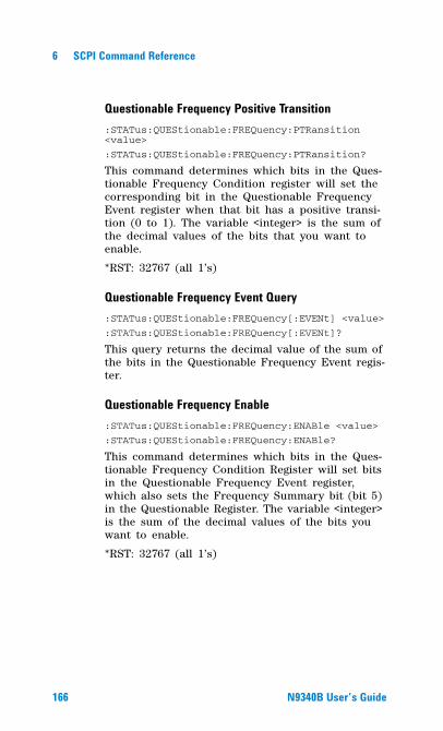
6 SCPI Command Reference
Questionable Frequency Positive Transition:STATus:QUEStionable:FREQuency:PTRansition <value>
:STATus:QUEStionable:FREQuency:PTRansition?
This command determines which bits in the Ques-tionable Frequency Condition register will set the corresponding bit in the Questionable Frequency Event register when that bit has a positive transi-tion (0 to 1). The variable <integer> is the sum of the decimal values of the bits that you want to enable.
*RST: 32767 (all 1’s)
Questionable Frequency Event Query:STATus:QUEStionable:FREQuency[:EVENt] <value>
:STATus:QUEStionable:FREQuency[:EVENt]?
This query returns the decimal value of the sum of the bits in the Questionable Frequency Event regis-ter.
Questionable Frequency Enable:STATus:QUEStionable:FREQuency:ENABle <value>
:STATus:QUEStionable:FREQuency:ENABle?
This command determines which bits in the Ques-tionable Frequency Condition Register will set bits in the Questionable Frequency Event register, which also sets the Frequency Summary bit (bit 5) in the Questionable Register. The variable <integer> is the sum of the decimal values of the bits you want to enable.
*RST: 32767 (all 1’s)
166 N9340B User�s Guide
SCPI Command Reference 6
Questionable Condition:STATus:QUEStionable:CONDition <value>
:STATus:QUEStionable:CONDition?
This command sets the decimal value of the sum of the bits in the Questionable Condition register.
Questionable Negative Transition:STATus:QUEStionable:NTRansition <value>
:STATus:QUEStionable:NTRansition?
This command determines which bits in the Ques-tionable Condition register will set the correspond-ing bit in the Questionable Event register when that bit has a negative transition (1 to 0). The variable <integer> is the sum of the decimal values of the bits that you want to enable.
*RST: 0
Questionable Positive Transition:STATus:QUEStionable:PTRansition <value>
:STATus:QUEStionable:PTRansition?
This command determines which bits in the Ques-tionable Condition register will set the correspond-ing bit in the Questionable Event register when that bit has a positive transition (0 to 1). The vari-able <integer> is the sum of the decimal values of the bits that you want to enable.
*RST: 32767 (all 1’s)
Questionable Event Query:STATus:QUEStionable[:EVENt] <value>
:STATus:QUEStionable[:EVENt]?
This command sets the decimal value of the sum of the bits in the Questionable Event register.
N9340B User�s Guide 167
6 SCPI Command Reference
Questionable Enable:STATus:QUEStionable:ENABle <value>:STATus:QUEStionable:ENABle?
This command determines which bits in the Ques-tionable Condition Register will set bits in the Questionable Event register, which also sets the Questionable Status Summary bit (bit3) in the Sta-tus Byte Register. The variable <integer> is the sum of the decimal values of the bits you want to enable.*RST: 0
Operation Condition:STATus:OPERation:CONDition <value>:STATus:OPERation:CONDition?
This command sets the decimal value of the sum of the bits in the Status Operation Condition register.
Operation Negative Transition:STATus:OPERation:NTRansition <value>:STATus:OPERation:NTRansition?
This command determines which bits in the Opera-tion Condition register will set the corresponding bit in the Operation Event register when that bit has a negative transition (1 to 0). The variable <integer> is the sum of the decimal values of the bits that you want to enable.*RST: 0
Operation Positive Transition:STATus:OPERation:PTRansition <value>:STATus:OPERation:PTRansition?
This command determines which bits in the Operation Condition register will set the corresponding bit in the Operation Event register when that bit has a positive transition (0 to 1). The variable <integer> is the sum of the decimal values of the bits that you want to enable.*RST: 32767 (all 1’s)
168 N9340B User�s Guide
SCPI Command Reference 6
Operation Event:STATus:OPERation[:EVENt] <value>
:STATus:OPERation[:EVENt]?
This command sets the decimal value of the sum of the bits in the Operation Event register.
Operation Enable:STATus:OPERation:ENABle <value>
:STATus:OPERation:ENABle?
This command determines which bits in the Operation Condition Register will set bits in the Operation Event register, which also sets the Operation Status Summary bit (bit 7) in the Status Byte Register. The variable <integer> is the sum of the decimal values of the bits you want to enable.
*RST: 0
Preset the Status Byte:STATUs:PRESet
Sets bits in most of the enable and transition registers to their default state.
Questionable Calibration Condition:STATus:QUEStionable:CALibration:CONDition <value>
:STATus:QUEStionable:CALibration:CONDition?
This command sets the decimal value of the sum of the bits in the Questionable Calibration Condition register.
Questionable Calibration Negative Transition:STATus:QUEStionable:CALibration:NTRansition <value>
:STATus:QUEStionable:CALibration:NTRansition?
This command determines which bits in the Questionable Calibration Condition register will set the corresponding bit in the Questionable Calibration Event register when that bit has a
N9340B User�s Guide 169
6 SCPI Command Reference
negative transition (1 to 0). The variable <integer> is the sum of the decimal values of the bits that you want to enable.
*RST: 0
Questionable Calibration Positive Transition:STATus:QUEStionable:CALibration:PTRansition <value>
:STATus:QUEStionable:CALibration:PTRansition?
This command determines which bits in the Ques-tionable Calibration Condition register will set the corresponding bit in the Questionable Calibration Event register when that bit has a positive transi-tion (0 to 1). The variable <integer> is the sum of the decimal values of the bits that you want to enable.
*RST: 32767 (all 1’s)
Questionable Calibration Event Query:STATus:QUEStionable:CALibration[:EVENt] <value>
:STATus:QUEStionable:CALibration[:EVENt]?
This query returns the decimal value of the sum of the bits in the Questionable Calibration Event reg-ister. The data in this register is latched until it is queried. Once queried, the data is cleared.
Questionable Calibration Enable:STATus:QUEStionable:CALibration:ENABle <value>
:STATus:QUEStionable:CALibration:ENABle?
This command determines which bits in the Questionable Calibration Condition Register will set bits in the Questionable Calibration Event register, which also sets the Calibration Summary bit (bit 8) in the Questionable Register. The variable <integer> is the sum of the decimal values of the bits you want to enable.
170 N9340B User�s Guide
SCPI Command Reference 6
Questionable Integrity Uncalibrated Condition:STATus:QUEStionable:INTegrity:UNCalibrated:CONDition <value>
:STATus:QUEStionable:INTegrity:UNCalibrated:CONDition?
This command sets the decimal value of the sum of the bits in the Questionable Integrity Uncalibrated Condition register.
Questionable Integrity Uncalibrated Negative Transition:STATus:QUEStionable:INTegrity:UNCalibrated:NTRansition <value>
:STATus:QUEStionable:INTegrity:UNCalibrated:NTRansition?
This command determines which bits in the Questionable Integrity Uncalibrated Condition register will set the corresponding bit in the Questionable Integrity Uncalibrated Event register when that bit has a negative transition (1 to 0). The variable <integer> is the sum of the decimal values of the bits that you want to enable.
*RST: 0
Questionable Integrity Uncalibrated Positive Transition:STATus:QUEStionable:INTegrity:UNCalibrated:PTRansition <value>
:STATus:QUEStionable:INTegrity:UNCalibrated:PTRansition?
This command determines which bits in the Ques-tionable Integrity Uncalibrated Condition register will set the corresponding bit in the Questionable Integrity Uncalibrated Event register when that bit has a positive transition (0 to 1). The variable <integer> is the sum of the decimal values of the bits that you want to enable.
*RST: 32767 (all 1’s)
N9340B User�s Guide 171
6 SCPI Command Reference
Questionable Integrity Uncalibrated Event:STATus:QUEStionable:INTegrity:UNCalibrated[:EVENt] <value>
:STATus:QUEStionable:INTegrity:UNCalibrated[EVENt]?
This command sets the decimal value of the sum of the bits in the Questionable Integrity Uncalibrated Event register.
Questionable Integrity Uncalibrated Enable:STATus:QUEStionable:INTegrity:UNCalibrated:ENABle <value>
:STATus:QUEStionable:INTegrity:UNCalibrated:ENABle?
This command determines which bits in the Questionable Integrity Uncalibrated Condition Register will set bits in the Questionable Integrity Uncalibrated Event register, which also sets the Data Uncalibrated Summary bit (bit 3) in the Questionable Integrity Register. The variable <integer> is the sum of the decimal values of the bits you want to enable.
*RST: 32767
Questionable Integrity Condition:STATus:QUEStionable:INTegrity:CONDition <value>
:STATus:QUEStionable:INTegrity:CONDition?
This command sets the decimal value of the sum of the bits in the Questionable Integrity Condition register.
Questionable Integrity Negative Transition:STATus:QUEStionable:INTegrity:NTRansition <value>
:STATus:QUEStionable:INTegrity:NTRansition?
This command determines which bits in the Ques-tionable Integrity Condition register will set the corresponding bit in the Questionable Integrity Event register when that bit has a negative transi-
172 N9340B User�s Guide
SCPI Command Reference 6
tion (1 to 0). The variable <integer> is the sum of the decimal values of the bits that you want to enable.
*RST: 0
Questionable Integrity Positive Transition:STATus:QUEStionable:INTegrity:PTRansition <value>
:STATus:QUEStionable:INTegrity:PTRansition?
This command determines which bits in the Ques-tionable Integrity Condition register will set the corresponding bit in the Questionable Integrity Event register when that bit has a positive transi-tion (0 to 1). The variable <integer> is the sum of the decimal values of the bits that you want to enable.
*RST: 32767 (all 1’s)
Questionable Integrity Event:STATus:QUEStionable:INTegrity[:EVENt] <value>
:STATus:QUEStionable:INTegrity[:EVENt]?
This command sets the decimal value of the sum of the bits in the Questionable Integrity Event regis-ter.
Questionable Integrity Enable:STATus:QUEStionable:INTegrity:ENABle <value>
:STATus:QUEStionable:INTegrity:ENABle ?
This command determines which bits in the Ques-tionable Integrity Condition Register will set bits in the Questionable Integrity Event register, which also sets the Integrity Summary bit (bit 9) in the Questionable Register. The variable <integer> is the sum of the decimal values of the bits you want to enable.
*RST: 32767 (all 1’s)
N9340B User�s Guide 173
6 SCPI Command Reference
SYSTem Subsystem
This subsystem is used to set the controls and parameters associated with the overall system settings. These functions are not related to instrument performance.
Ext Input:SYSTem:CONFigure:PORT REF|TRIGger
:SYSTem:CONFigure:PORT?
This command toggles the channel for external input between Ref and Trig.
Date Query:SYSTem:DATE?
This query inquires the date of the real- time clock of the analyzer.
Time Query:SYSTem:TIME?
This query inquires the time of the real- time clock of the analyzer.
Error Information Query:SYSTem:ERRor[:NEXT]?
This query inquiries the earlier entry to the error queue and then deletes that entry. .
Key Access: [SYS] > {Setting} > {Ext input}
Key Access: [SYS] > {Show Error}
174 N9340B User�s Guide
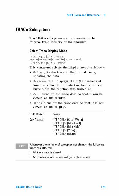
SCPI Command Reference 6
TRACe Subsystem
The TRACe subsystem controls access to the internal trace memory of the analyzer.
Select Trace Display Mode :TRACe[1]|2|3|4:MODE WRITe|MAXHole|MINHole|VIEW|BLANk
:TRACe[1]|2|3|4:MODE?
This command selects the display mode as follows:
• Write puts the trace in the normal mode, updating the data.
• Maximum Hold displays the highest measured trace value for all the data that has been mea-sured since the function was turned on.
• View turns on the trace data so that it can be viewed on the display.
• Blank turns off the trace data so that it is not viewed on the display.
*RST State: WriteKey Access: [TRACE] > {Clear Write}
[TRACE] > {Max Hold} [TRACE] > {Min Hold} [TRACE] > {View} [TRACE] > {Blank}
NOTE Whenever the number of sweep points change, the following functions affected:� All trace data is erased� Any traces in view mode will go to blank mode.
N9340B User�s Guide 175
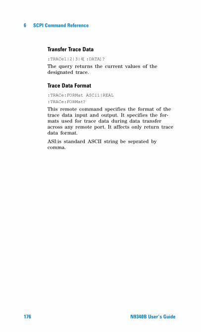
6 SCPI Command Reference
Transfer Trace Data:TRACe1|2|3|4[:DATA]?
The query returns the current values of the designated trace.
Trace Data Format:TRACe:FORMat ASCii|REAL:TRACe:FORMat?
This remote command specifies the format of the trace data input and output. It specifies the for-mats used for trace data during data transfer across any remote port. It affects only return trace data format.
ASI:is standard ASCII string be seprated by comma.
176 N9340B User�s Guide
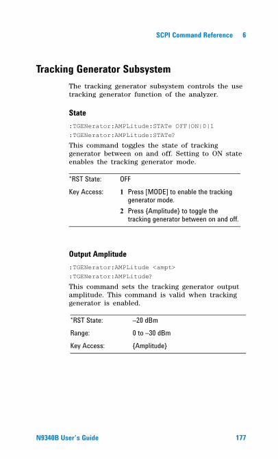
SCPI Command Reference 6
Tracking Generator SubsystemThe tracking generator subsystem controls the use tracking generator function of the analyzer.
State:TGENerator:AMPLitude:STATe OFF|ON|0|1:TGENerator:AMPLitude:STATe?
This command toggles the state of tracking generator between on and off. Setting to ON state enables the tracking generator mode.
Output Amplitude:TGENerator:AMPLitude <ampt>:TGENerator:AMPLitude?
This command sets the tracking generator output amplitude. This command is valid when tracking generator is enabled.
*RST State: OFF
Key Access: 1 Press [MODE] to enable the tracking generator mode.
2 Press {Amplitude} to toggle the tracking generator between on and off.
*RST State: �20 dBmRange: 0 to �30 dBmKey Access: {Amplitude}
N9340B User�s Guide 177
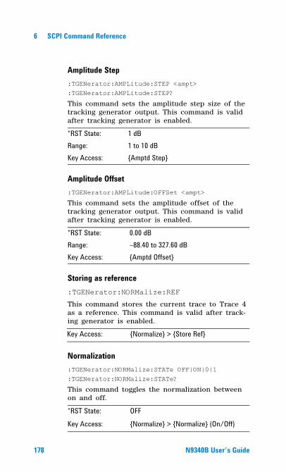
6 SCPI Command Reference
Amplitude Step:TGENerator:AMPLitude:STEP <ampt>:TGENerator:AMPLitude:STEP?
This command sets the amplitude step size of the tracking generator output. This command is valid after tracking generator is enabled.
Amplitude Offset:TGENerator:AMPLitude:OFFSet <ampt>
This command sets the amplitude offset of the tracking generator output. This command is valid after tracking generator is enabled.
Storing as reference:TGENerator:NORMalize:REF
This command stores the current trace to Trace 4 as a reference. This command is valid after track-ing generator is enabled.
Normalization:TGENerator:NORMalize:STATe OFF|ON|0|1:TGENerator:NORMalize:STATe?
This command toggles the normalization between on and off.
*RST State: 1 dBRange: 1 to 10 dBKey Access: {Amptd Step}
*RST State: 0.00 dBRange: �88.40 to 327.60 dBKey Access: {Amptd Offset}
Key Access: {Normalize} > {Store Ref}
*RST State: OFFKey Access: {Normalize} > {Normalize} (On/Off)
178 N9340B User�s Guide
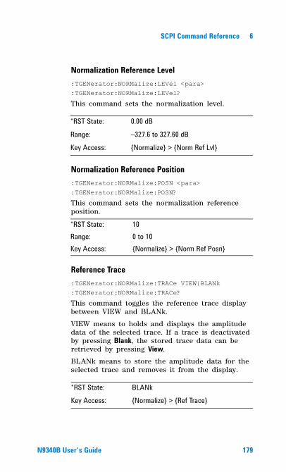
SCPI Command Reference 6
Normalization Reference Level:TGENerator:NORMalize:LEVel <para>:TGENerator:NORMalize:LEVel?
This command sets the normalization level.
Normalization Reference Position:TGENerator:NORMalize:POSN <para>:TGENerator:NORMalize:POSN?
This command sets the normalization reference position.
Reference Trace:TGENerator:NORMalize:TRACe VIEW|BLANk:TGENerator:NORMalize:TRACe?
This command toggles the reference trace display between VIEW and BLANk.
VIEW means to holds and displays the amplitude data of the selected trace. If a trace is deactivated by pressing Blank, the stored trace data can be retrieved by pressing View.
BLANk means to store the amplitude data for the selected trace and removes it from the display.
*RST State: 0.00 dB
Range: �327.6 to 327.60 dBKey Access: {Normalize} > {Norm Ref Lvl}
*RST State: 10Range: 0 to 10Key Access: {Normalize} > {Norm Ref Posn}
*RST State: BLANkKey Access: {Normalize} > {Ref Trace}
N9340B User�s Guide 179
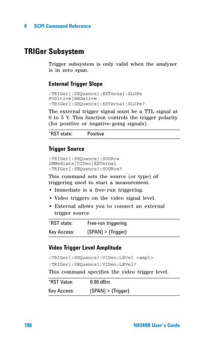
6 SCPI Command Reference
TRIGer SubsystemTrigger subsystem is only valid when the analyzer is in zero span.
External Trigger Slope:TRIGer[:SEQuence]:EXTernal:SLOPe POSitive|NEGative:TRIGer[:SEQuence]:EXTernal:SLOPe?
The external trigger signal must be a TTL signal at 0 to 5 V. This function controls the trigger polarity (for positive or negative- going signals).
Trigger Source:TRIGer[:SEQuence]:SOURce IMMediate|VIDeo|EXTernal:TRIGer[:SEQuence]:SOURce?
This command sets the source (or type) of triggering used to start a measurement. • Immediate is a free- run triggering.
• Video triggers on the video signal level.
• External allows you to connect an external trigger source.
Video Trigger Level Amplitude:TRIGer[:SEQuence]:VIDeo:LEVel <ampl>
:TRIGer[:SEQuence]:VIDeo:LEVel?
This command specifies the video trigger level.
*RST state: Positive
*RST state: Free-run triggeringKey Access: [SPAN] > {Trigger}
*RST Value: 0.00 dBmKey Access: [SPAN] > {Trigger}
180 N9340B User�s Guide
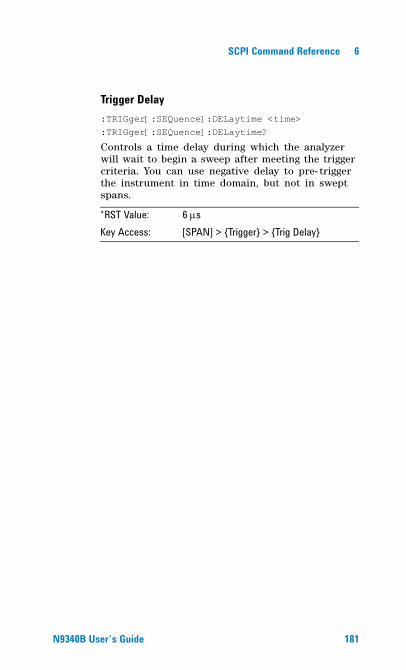
SCPI Command Reference 6
Trigger Delay:TRIGger[:SEQuence]:DELaytime <time>:TRIGger[:SEQuence]:DELaytime?
Controls a time delay during which the analyzer will wait to begin a sweep after meeting the trigger criteria. You can use negative delay to pre- trigger the instrument in time domain, but not in swept spans.
*RST Value: 6 μsKey Access: [SPAN] > {Trigger} > {Trig Delay}
N9340B User�s Guide 181
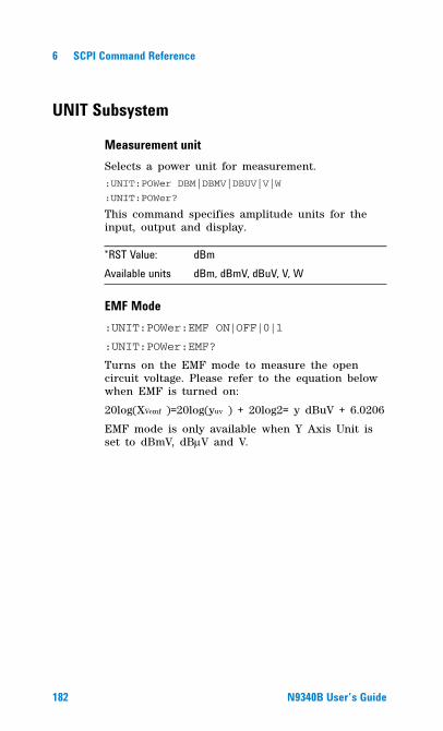
6 SCPI Command Reference
UNIT Subsystem
Measurement unitSelects a power unit for measurement.:UNIT:POWer DBM|DBMV|DBUV|V|W
:UNIT:POWer?
This command specifies amplitude units for the input, output and display.
EMF Mode:UNIT:POWer:EMF ON|OFF|0|1
:UNIT:POWer:EMF?
Turns on the EMF mode to measure the open circuit voltage. Please refer to the equation below when EMF is turned on:
20log(XVemf )=20log(yuv ) + 20log2= y dBuV + 6.0206
EMF mode is only available when Y Axis Unit is set to dBmV, dBμV and V.
*RST Value: dBmAvailable units dBm, dBmV, dBuV, V, W
182 N9340B User�s Guide
Agilent N9340B Handheld Spectrum Analyzer
7Error Messages
This chapter contains Error Message information and definitions used by the analyzer.
183Agilent Technologies

7 Error Messages
184 N9340B User�s Guide
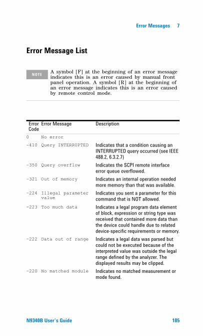
Error Messages 7
Error Message List
NOTE A symbol [F] at the beginning of an error message indicates this is an error caused by manual front panel operation. A symbol [R] at the beginning of an error message indicates this is an error caused by remote control mode.
Error Code
Error Message Description
0 No error
�410 Query INTERRUPTED Indicates that a condition causing an INTERRUPTED query occurred (see IEEE 488.2, 6.3.2.7)
�350 Query overflow Indicates the SCPI remote interface error queue overflowed.
�321 Out of memory Indicates an internal operation needed more memory than that was available.
�224 Illegal parameter value
Indicates you sent a parameter for this command that is NOT allowed.
�223 Too much data Indicates a legal program data element of block, expression or string type was received that contained more data than the device could handle due to related device-specific requirements or memory.
�222 Data out of range Indicates a legal data was parsed but could not be executed because of the interpreted value was outside the legal range defined by the analyzer. The displayed results may be clipped.
�220 No matched module Indicates no matched measurement or mode found.
N9340B User�s Guide 185
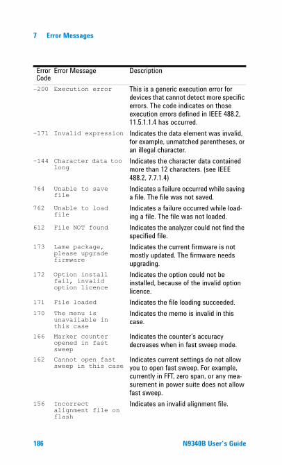
7 Error Messages
�200 Execution error This is a generic execution error for devices that cannot detect more specific errors. The code indicates on those execution errors defined in IEEE 488.2, 11.5.1.1.4 has occurred.
�171 Invalid expression Indicates the data element was invalid, for example, unmatched parentheses, or an illegal character.
�144 Character data too long
Indicates the character data contained more than 12 characters. (see IEEE 488.2, 7.7.1.4)
764 Unable to save file
Indicates a failure occurred while saving a file. The file was not saved.
762 Unable to load file
Indicates a failure occurred while load-ing a file. The file was not loaded.
612 File NOT found Indicates the analyzer could not find the specified file.
173 Lame package, please upgrade firmware
Indicates the current firmware is not mostly updated. The firmware needs upgrading.
172 Option install fail, invalid option licence
Indicates the option could not be installed, because of the invalid option licence.
171 File loaded Indicates the file loading succeeded.170 The menu is
unavailable in this case
Indicates the memo is invalid in this case.
166 Marker counter opened in fast sweep
Indicates the counter�s accuracy decreases when in fast sweep mode.
162 Cannot open fast sweep in this case
Indicates current settings do not allow you to open fast sweep. For example, currently in FFT, zero span, or any mea-surement in power suite does not allow fast sweep.
156 Incorrect alignment file on flash
Indicates an invalid alignment file.
Error Code
Error Message Description
186 N9340B User�s Guide
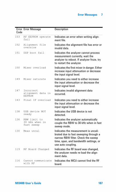
Error Messages 7
153 RF EEPROM operate fail
Indicates an error when writing align-ment file.
152 Alignment file oversize
Indicates the alignment file has error or invalid data.
151 DSP boot fail Indicates the analyzer cannot process measurement currently, wait the analyzer to reboot. If analyzer froze, try to restart the analyzer.
150 Mixer overload Indicates the first mixer in danger. Either increase input attenuation or decrease the input signal level.
149 Mixer saturate Indicates you need to either increase the input attenuation or decrease the input signal level.
147 Incorrect alignment data in EEPROM
Indicates invalid alignment data occurred.
143 Final IF overload Indicates you need to either increase the input attenuation or decrease the input signal level.
138 USB device NOT ready
Indicates the USB device is not detected.
136 RBW limit to 30 kHz when in fast sweep
Indicates the analyzer automatically couple the RBW to 30 kHz when in fast sweep mode.
130 Meas uncal Indicates the measurement is uncali-brated due to fast sweeping through a narrow RBW filter. Check the sweep time, span, and bandwidth settings, or use auto coupling.
119 RF Board Changed Indicates the RF board was changed, the analyzer needs re-load the align-ment data.
116 Cannot communicate with RF
Indicates the MCU cannot find the RF board.
Error Code
Error Message Description
N9340B User�s Guide 187

7 Error Messages
188 N9340B User�s Guide
Agilent N9340B Handheld Spectrum Analyzer
8Menu Map
This chapter contains Menu Maps that visually present the menus and submenus that are accessed by pressing the Hardkeys and Softkey menu selections in the instrument.
This is a quick reference guide for the experienced user.
189Agilent Technologies
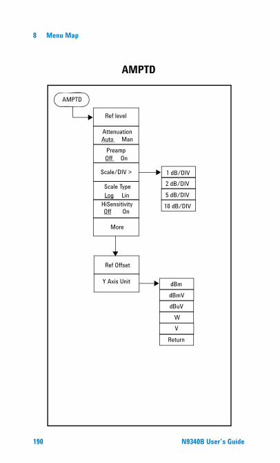
8 Menu Map
AMPTD
AMPTD
Ref level
AttenuationAuto Man
PreampOff On
Scale/DIV >
Scale TypeLog Lin
HiSensitivity
More
dBm
1 dB/DIV2 dB/DIV
5 dB/DIV10 dB/DIV
dBmVdBuV
WV
Return
Off On
Y Axis Unit
Ref Offset
190 N9340B User�s Guide
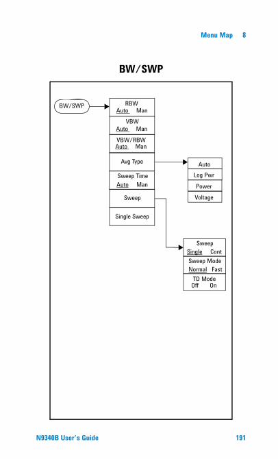
Menu Map 8
BW/SWP RBW
VBW
VBW/RBW
Avg Type
Sweep TimeAuto Man
Sweep
Single Sweep
AutoLog Pwr
PowerVoltage
TD Mode
Auto Man
Auto Man
Auto Man
Sweep Single ContSweep ModeNormal Fast
Off On
BW/SWP
N9340B User�s Guide 191
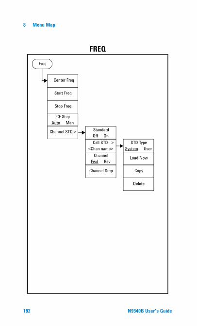
8 Menu Map
Freq
Center Freq
CF StepAuto Man
Start Freq
Stop Freq
Channel STD > StandardOff On
Call STD ><Chan name>
ChannelFwd Rev
Channel Step
STD TypeSystem User
Load Now
Copy
Delete
FREQ
192 N9340B User�s Guide
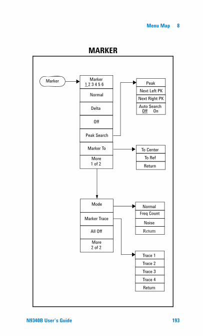
Menu Map 8
Marker Marker
Normal
Delta
Off
Peak Search
Marker To
More
Peak
Auto Search
1 2 3 4 5 6Next Left PK
Next Right PK
1 of 2
To CenterTo Ref
Return
Mode
All Off
Marker Trace
NormalFreq Count
NoiseReturn
More2 of 2
Trace 1
Trace 3Trace 4
Trace 2
Return
Off On
MARKER
N9340B User�s Guide 193
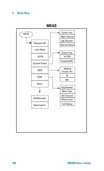
8 Menu Map
MEAS
MEAS
Measure Off
Limit Mask
ACPR
Channel Power
OBW Method
%
dBc
Center FreqInt BW
Channel BW
Center Freq
Adj ChannelChannel Space
Main Channel
Percent dBc
SEM
More
FieldStrength
Spectrogram
Avg NumberMeas Type
Ref ChannelOffset/Limit
Fail Setting
194 N9340B User�s Guide
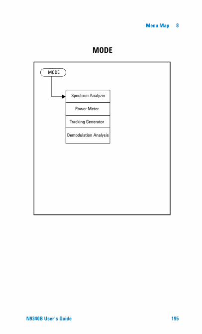
Menu Map 8
MODE
MODE
Spectrum Analyzer
Tracking Generator
Power Meter
Demodulation Analysis
N9340B User�s Guide 195
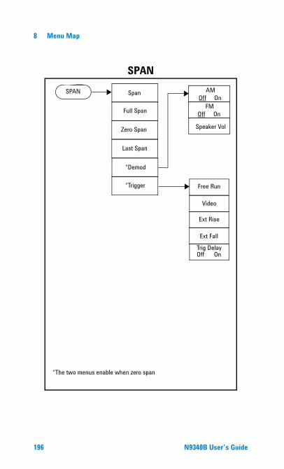
8 Menu Map
SPAN Span
Full Span
Zero Span
Last Span
*Demod
*Trigger
*The two menus enable when zero span
AMOff On
FMOff On
Speaker Vol
Free Run
Video
Ext Rise
Ext Fall
Off OnTrig Delay
SPAN
196 N9340B User�s Guide
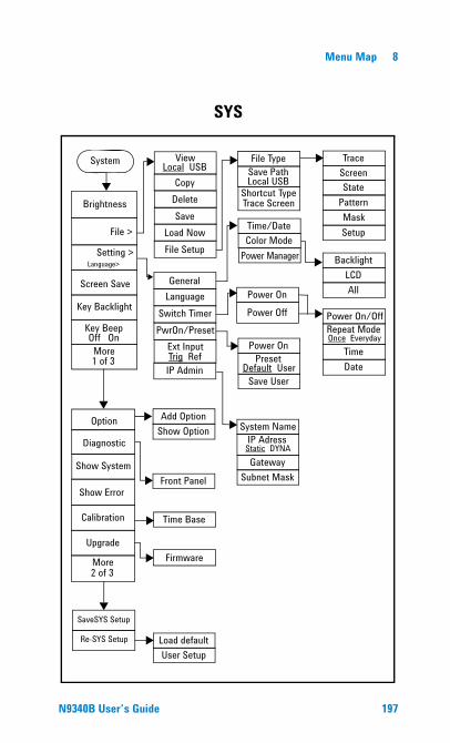
Menu Map 8
SYS
System
Brightness
Setting >
Key Backlight
File >
General
Ext InputTrig Ref
Language
More1 of 3
Show System
Show Error
Calibration
More2 of 3
Option
Diagnostic
IP Admin
ViewLocal USB
CopyDeleteSave
Load NowFile Setup
Time Base
PresetDefault User
Front Panel
Time/DateColor Mode
Power Manager
File TypeSave Path
Backlight
TraceScreenState
Pattern
Load defaultUser Setup
MaskSetup
Re-SYS Setup
Add OptionShow Option
Screen Save
Language> LCDAll
Shortcut Type
Switch TimerPwrOn/PresetKey Beep
Power On
Save User
UpgradeFirmware
SaveSYS Setup
IP AdressStatic DYNA
System Name
GatewaySubnet Mask
Local USB
Trace Screen
Power OnPower Off
Repeat ModeOnce Everyday
Power On/Off
TimeDate
Off On
N9340B User�s Guide 197
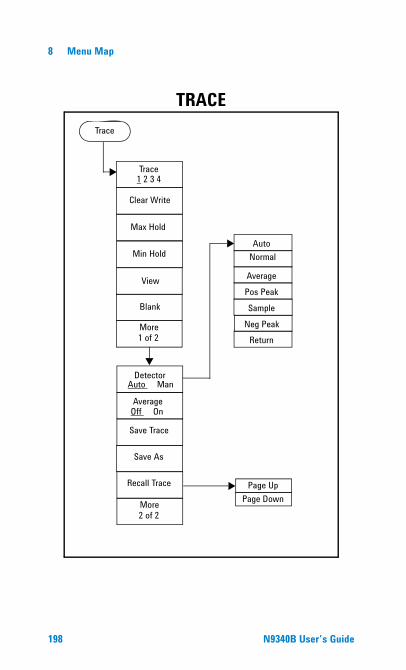
8 Menu Map
Trace
Trace
Clear Write
Max Hold
Min Hold
View
Blank
More
1 2 3 4
1 of 2
Detector
Save Trace
Average
AutoNormal
AveragePos Peak
More2 of 2
Auto Man
Off On
Save As
Recall Trace
SampleNeg Peak
Return
Page UpPage Down
TRACE
198 N9340B User�s Guide
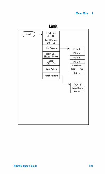
Menu Map 8
Limit Type
Beep
Save Pattern
Upper Lower
Limit Limit Line
Limit Pattern
Recall Pattern
Off On
Off On
Off On
Point 1Point 2
Point 3Point 4
X Axis Unit
Return
Set Pattern
Freq Time
Page UpPage Down
Return
Limit
N9340B User�s Guide 199

8 Menu Map
200 N9340B User�s Guide
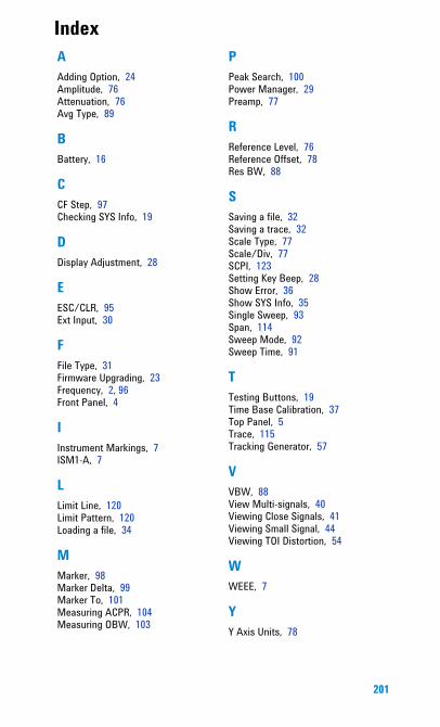
Index
AAdding Option, 24Amplitude, 76Attenuation, 76Avg Type, 89BBattery, 16
CCF Step, 97Checking SYS Info, 19
DDisplay Adjustment, 28
EESC/CLR, 95Ext Input, 30
FFile Type, 31Firmware Upgrading, 23Frequency, 2, 96Front Panel, 4
IInstrument Markings, 7ISM1-A, 7
LLimit Line, 120Limit Pattern, 120Loading a file, 34
MMarker, 98Marker Delta, 99Marker To, 101Measuring ACPR, 104Measuring OBW, 103
PPeak Search, 100Power Manager, 29Preamp, 77
RReference Level, 76Reference Offset, 78Res BW, 88
SSaving a file, 32Saving a trace, 32Scale Type, 77Scale/Div, 77SCPI, 123Setting Key Beep, 28Show Error, 36Show SYS Info, 35Single Sweep, 93Span, 114Sweep Mode, 92Sweep Time, 91
TTesting Buttons, 19Time Base Calibration, 37Top Panel, 5Trace, 115Tracking Generator, 57
VVBW, 88View Multi-signals, 40Viewing Close Signals, 41Viewing Small Signal, 44Viewing TOI Distortion, 54
WWEEE, 7
YY Axis Units, 78
201

202
DECLARATION OF CONFORMITY According to EN ISO/IEC 17050-1:2004
Generic DoC example
Manufacturer’s Name: Agilent Technologies (Chengdu) Co., Ltd.
Manufacturer’s Address:
Qianfeng Hi-Tech Industry Park, Chengdu Hi-Tech Industrial Development Zone (West District), Chengdu, 611731 P.R.C.
Declares under sole responsibility that the product as originally delivered Product Name: Handheld Spectrum Analyzer Model Number: N9340B Product Options: This declaration covers all options of the above product(s) complies with the essential requirements of the following applicable European Directives, and carries the CE marking accordingly:
Low Voltage Directive (2006/95/EC) EMC Directive (89/336/EEC, amended by 93/68/EEC)
and conforms with the following product standards: EMC Standard Limit IEC 61326:2002/ EN 61326:1997+A1:1998 +A2:2001+A3:2003 Reference Standards CISPR 11:1990 / EN 55011:1990 Class A Group 1 IEC 61000-4-2:1995 / EN 61000-4-2:1995 4 kV/4 kV contact/air IEC 61000-4-3:1995 / EN 61000-4-3/1996 3 V/m, 80-1000 MHz IEC 61000-4-4:1995 / EN 61000-4-4:1995 0.5 kV signal lines, 1 kV power lines IEC 61000-4-5:1995 / EN 61000-4-5:1995 0.5 kV line-line, 1 kV line-ground IEC 61000-4-6:1996 / EN 61000-4-6:1996 3 V, 0.15-80 MHz IEC 61000-4-8:1993 / EN 61000-4-8:1993 30 A/m (only on sensitive equipment) IEC 61000-4-11:1994 / EN 61000-4-11:1994 1 cycle, >95% Canada: ICES-001:2004 Australia/New Zealand: AS/NZS CISPR 11:2004 The product was tested in a typical configuration with Agilent Technologies test systems. Safety IEC 61010-1:2001 / EN 61010-1:2001
Canada: CAN/CSA-C22.2 No. 61010-1-04, USA: ANSI/UL 61010-1:2004,
Supplementary Information: This DoC applies to above-listed products placed on the EU market after:
Mar 28, 2008
Date Shi Wen
Quality Manager
For further information, please contact your local Agilent Technologies sales office, agent or distributor, or Agilent Technologies Deutschland GmbH, Herrenberger Straße 130, D 71034 Böblingen, Germany.
Template: A5971-5302-2, Rev. B.01 N9340B Rev 1.0

www.agilent.com
© Agilent Technologies, Inc. 2008
Printed in China May 2008
*N9340-90008*N9340-90008
!"