agilent l4600a radio test set - rl...
TRANSCRIPT

AgilentL4600A Radio Test Set 2 MHz to 2.5 GHz Technical Overview
Designed with portability, ruggedness, and ease-of-use in mind.
This radio test set simplifies radio testing and bridges the gapbetween repair facilities and harsh operational field environments – use the same radio test set for testing, troubleshooting, and repair!
2
Tough Enough for the Military (Option 340) The L4600A is the U.S. Army AN/PRM-35 program's Operational Tester. A single-box measurement solution makes sense only if it can stand up to harsh field use and unexpected weather. We designed the Agilent L4600A radio test set to be portable, rugged, and weather resistant.
A magnesium alloy case with extensive internalRF shielding protects the components and reducesinterference that could impact measurement accuracy,and makes the radio test set easy to handle and carry.
Gasket sealed ports, a water-resistant rubber membrane,and a dust-proof case design (no fan, no vents) addsto the ongoing confidence of your measurements.
The soft carry case and rubber bumpers protect theradio test set from damage during transportation and use.
We know that you'll want to add new capabilities as radios add complexity, so we made sure that all functionality upgrades will be implemented through firmware or hardware inside the case. The Agilent L4600A radio test set grows in functionality without growing in size. The field-rugged design is never compromised by awkward external modules.
Tests Military SINCGARS Radioswith Guided Measurements (Option 340)
A single softkey selection, from the L4600A's main menu, activates an easy step-by-step "Guided Measurement" mode. In this mode, connection diagrams along with directions help guide you through a set of tests that once completed, give you the knowledge and confidence that you are deploying athoroughly tested and working SINCGARS radio that will transmit and receive your call when it really counts.
Requires Less Training (Option 340)
The "Guided Measurement" mode requires less training, so all testing can be completed and interpreted by new people and people with little training; this reduces the need for in-depth measurement knowledge.
Helps Eliminate Radios that areMisdiagnosed with "No Fault Found"
Make measurements properly and accurately so that good radios are not taken out of service.
Designed to be Versatile
The L4600A builds upon the proven performance ofAgilent’s industry leading wireless base station test set.It was designed to meet the needs of a multitude of radio tests and provide fast, reliable measurements of a radio's transmitter and receiver parameters as well as finding faults in antennas, cables, power amplifiers, and interconnects.
Isolates Antenna and Cable Problems
Many radio faults lie in the cabling and/or antenna and not with the radio. Measure antenna's VSWR or return loss and find distance to fault in cables.
Built-In Bench Top Functionality
In addition to its extensive operational capability,the L4600A fulfills the needs of the more advanced user with built-in "bench top" functionality.
Using the menu driven interface, the L4600A can betransformed into a signal generator (for receiver test),a tuned receiver (for transmitter test),a network analyzer (for antenna/cable test),or a spectrum analyzer (for troubleshooting).
Software-Defined ArchitectureLowers Your Cost of Ownership
The L4600A exploits a software-defined architecture thatprotects your investment with upgradable firmware and guards against obsolescence or the need to buy additional test sets. When a change of protocol is required, there is no need to change the radio test set. This saves money bymaking the radio test set more flexible and reduces thenumber of radio test sets that have to be maintained.
Future Upgrades to Additional Radio Formats
Upgradable firmware, with license-key enabled upgrades, allows for future updates and enhancements to the capability of the test set. This enables you to easily add non-hardware options or update functional improvements in the field, with-out the need to return the radio test set to the factory. Upgradable firmware being developed will enable the L4600A in the future to test JTRS radios up to 2.5 GHz as well as other radio formats.2
All-In-One Radio Test SetThe Agilent L4600A Radio Test Set does it all!

3
Easy Access in a Rugged, Lightweight, Protective Case
Battery LED Indicators Changes color to indicate battery status.
Magnesium Alloy Case Provides enhanced heat distribution in a strong, lightweight, protective shell that keeps the test set free of moister and dirt – completely sealed with no vents or fans.
Gasket Sealed Ports Protect components from moisture and harsh weather.Color Display
High resolution, 10.4" transfl ective sealed color display stays viewable in darkness, shade, direct sunlight, and at wide viewing angles.
Rubber Bumpers Protect the unit in rugged fi eld environments.
Compact Flash and PCMCIA Cards Enables storage of test data in .xls fi le format, screen captures as PNG graphics fi les, and a mechanism for fi rmware upgrades.
Large Backlit-Keys Protected by a water-resistant rubber membrane, enables easy navigation under all lighting and weather conditions – even with gloves on.
Help Button Displays measurement information.
Battery Access Panel Quickly change batteries through an easy access panel – no tools required. With two batteries installed, you can "hot-swap" batteries which allows for continuous uninterrupted use – no need to power down the test set.
LAN Port Enables data to be easily captured and transmitted to your network – allows remote control of the test set.

4
Easier to Interpret Test Results (Option 340)
Using the set of "Guided Measurements" requires lesstraining, so all testing can be completed and interpreted by operators with minimal training.
With a set of "Guided Measurements", tests can be made to confirm the radio's receiver sensitivity, verify the proper operation of the squelch circuit, or just measure the power and frequency accuracy of the radio to verify that it istransmitting properly.
Clearly Defined Test Setups (Option 340)
Make measurements quickly by following step-by-steptest setup instructions.
Perform FM Transmitter Test
The Radio Analyzer mode operates as an FM transmitter and demodulator, can use multiple filters, and measures the parameters related to a radio's transmitter. This allows you to analyze the signal that the radio is sending. Included in this mode, are frequency error (by showing offset from the set frequency), channel power, FM deviation,FM distortion, audio frequency, and SINAD.
Perform FM Receiver Test
The L4600A operates as a signal generator enabling testing of the radio's receiver.
Use the internal arbitrary waveform generator to simulate up to two FM signals: one tone at the radio's squelch fre-quency and one tone to simulate audio. For example, set up a receiver test for SINCGARS radios with a 150 Hz squelch tone (CTCSS) and an FM modulation source of 900 Hz (audio frequency test tone).
4
Designed with Portability, Ruggedness, and Ease-of-Use in MindSubstantially simplifies testing military radios in the harsh operational field environmentas well as providing comprehensive diagnostic capabilities in repair facilities.
Perform Tests Anywhere,Anytime, Regardless
of the Weather

5
Perform Functions Typically Only Availablein a High-Cost Network Analyzer
The L4600A performs specific RF measurements thatsimplify transmission line (cable) and antenna analysis: Return Loss, VSWR/SWR, Insertion Loss, andDistance-to-Fault (DTF). A softkey on the main menuactivates Antenna/Cable mode and allows you to perform:- One Port Insertion Loss- Distance to Fault- Two Port Insertion Loss- Return Loss
Find Defective CablesUsing One Port Insertion Loss
When you only have access to one end of a cable, you can perform a One-Port Insertion Loss measurement. There is no need to connect both ends of the cable or the device to the L4600A radio test set; the measurement is accurate for results up to 10 dB.
This can be especially useful when measuring the loss of a cable connected to an antenna or routed through a vehicle and only one end is easily accessible.
Measure Two-Port Insertion Lossof a Cable or other Device
When you have access to both ends of a cable, you can perform a Two-Port Insertion Loss measurement andmeasure the loss of a cable, attenuator, or other device by sweeping it over its specified frequency range.
Use Up to Four Markers to DesignateDistances to Faults in an Anntenna System
The Distance to Fault measurement uses markers todisplay the four worst faults of an antenna system.The results shown on the easy to understand displayhighlight problem locations or distance-to-fault.
Determine Return Loss (VSWR vs. Frequency)
VSWR or Return Loss vs. Frequency is useful for detecting problems in an anntenna feedline system or the cable of an antenna.
Isolate Cable and Antenna ProblemsBecause many radio faults lie in the cabling and/or antenna and not withthe radio, you can avoid returning good radios for repair, thus avoidingradio system down time — and that saves money!
Reduce or EliminateMis-diagnosed Radios with
"No Fault Found"

6
Drive-by-Test, Over-the-Air MeasurementsResolve Radio Installation Failures
Modulation Measurements• Spectrum Analyzer• Radio Analyzer•
The L4600A was designed as an operational andintermediate level radio tester, that enables you to quickly verify if a radio is transmitting the correct frequency and power.
You can efficiently and easily determine if the radio isfunctional. No need to connect to the radio under test.Simply connect the supplied antenna, key up a radio,and measure radio parameters over-the-air.
The L4600A contains an arbitrary waveform generator which enables testing of the receiver portion of the radio. With this arbitrary waveform generator, two FM signals can be used as modulation sources: modulate the carrier with both a test tone and a squelch tone. For example, set up a receiver test for a SINCGARS radio with an FM modulation source of 150 Hz squelch tone (CTCSS) and 900 Hz (audio frequency test tone).
If the SINCGARS radio is working, a display similar to the following shows a supplied FM Dual Tone (150 Hz along with 900 Hz) imposed on the 75 MHz CW and thendemodulated on the Radio Analyzer screen.
Save/Recall States
You don't have to remember the settings you were using when you see an issue during testing. With the press of a button, simply save the instrument state. Later, return to the same radio test set state - this can greatly enhanceproductivity by allowing the radio test set to return to aparticular setup and repeat a measurement.
Save/Recall on Compact Flash / PCMCIA Cards
Store test data, configure and define test parameters (as pass or fail), and save these files internally for future use or save them to Compact Flash or PCMCIA cards.
LAN
CompactFlash
PCMCIA
Upgrade with a Compact Flash / PCMCIA Card
Adding features with upgraded firmware is easy - install a Compact Flash or PCMCIA card with new firmware, cycle power, and follow the simple on screen prompts to install the new instrument firmware.
Remote Monitoring / Remote ControllableUsing a LAN Connection
Remote monitoring allows someone from a remote location to monitor and control the L4600A radio test set over aLAN connection.
Take control of the radio test set remotely - this allowsconfirmation of what the operational tester actually sees. This technique can greatly enhance abilities to confirm whether a radio actually has a real problem or not - it can help reduce or eliminate misdiagnosed radios that end up as "No Fault Found".
Convenient FeaturesSimplify your tasks.

7
Troubleshoot with aReal Spectrum Analyzer
Utilize a spectrum analyzer with a noise floor < –150 dBm for frequencies > 375 MHz. The selectable frequency span width ranges from 1 kHz to 2.5 GHz (usable to 2.7 GHz) with an effective resolution bandwidth as narrow as 10 Hz.Built-in spectrum emissions masks, occupied BW, Spectrogram, and Marker functions equip you with the functionality needed to troubleshoot complicated radio problems.
Create FM Modulated Signals with theBuilt-In Arbitrary Waveform Generator
The signal generator can be used simultaneously with other measurement functions so that the L4600A radio test set can act as both the source and the measurement device when making measurements.
Built-In Bench Top FunctionalityNo need to carry armfuls of tools.
Multiple Toolsare Built-In
8
Check that the Receiver is Workingon Your P25 Radio (Option 225)
Produce a C4FM I/Q moduation and transmit the signal to verify that your P25 radio is receiving the signal.
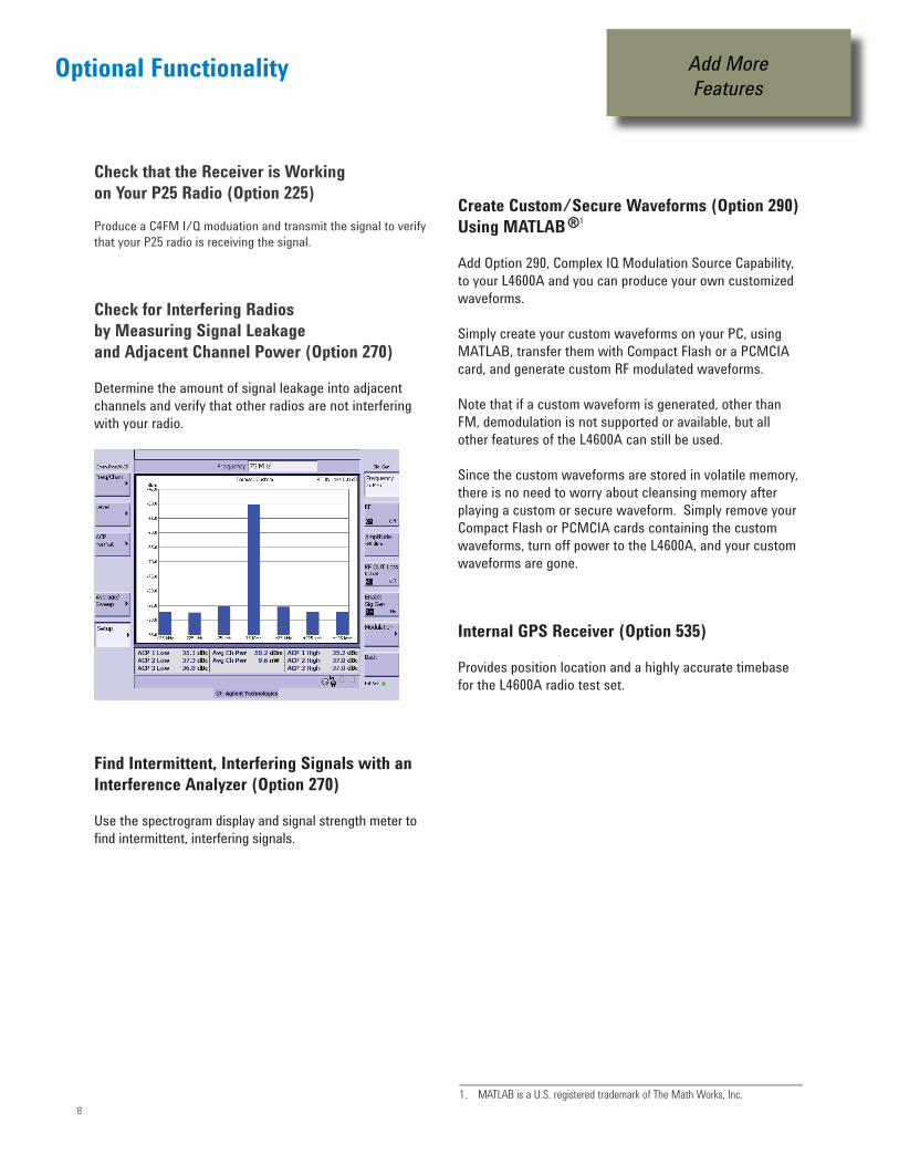
Check for Interfering Radiosby Measuring Signal Leakageand Adjacent Channel Power (Option 270)
Determine the amount of signal leakage into adjacentchannels and verify that other radios are not interfering with your radio.
Find Intermittent, Interfering Signals with an Interference Analyzer (Option 270)
Use the spectrogram display and signal strength meter to find intermittent, interfering signals.
Create Custom/Secure Waveforms (Option 290)Using MATLAB ®1
Add Option 290, Complex IQ Modulation Source Capability, to your L4600A and you can produce your own customized waveforms.
Simply create your custom waveforms on your PC, using MATLAB, transfer them with Compact Flash or a PCMCIA card, and generate custom RF modulated waveforms.
Note that if a custom waveform is generated, other than FM, demodulation is not supported or available, but all other features of the L4600A can still be used.
Since the custom waveforms are stored in volatile memory, there is no need to worry about cleansing memory after playing a custom or secure waveform. Simply remove your Compact Flash or PCMCIA cards containing the custom waveforms, turn off power to the L4600A, and your custom waveforms are gone.
Internal GPS Receiver (Option 535)
Provides position location and a highly accurate timebase for the L4600A radio test set.
Optional Functionality Add MoreFeatures
1. MATLAB is a U.S. registered trademark of The Math Works, Inc.

9
Specifications describe the L4600A radio test set's warrantedperformance and are valid over the entire operating/environmental range unless otherwise noted.
The distinction among specifications, typical performance, and nominal values are described as follows:• Bold type indicates a warranted, hard specification.
Specifications describe the performance of parameters covered by the product warranty (temperature = –10 to +50 °C, unless otherwise noted).
• Italics type indicates a typical value. Typical describes additional product performance information that is not covered by the product warranty. It is performance beyond specification that 80% of the units exhibit with a 95% confidence level over the temperature range 20 to 30 °C. Typical performance does not include measurement uncertainty.
• Normal type indicates a nominal value. Nominal values indicate expected performance, or describe product performance that is
useful in the application of the product, but is not covered by the product warranty.
Conditions Required for Meeting Specifications
• The L4600A radio test set is within its calibration cycle.
• The L4600A radio test set is under auto-couple control.
• Any L4600A radio test set that has been stored at a temperature range inside the allowed storage range, but outside the allowedoperating range must be stored at an ambient temperature within the allowed operating range for at least two hours before being turned on.
General Specifications
Unless otherwise noted, the following specifications apply to allmeasurements/tools using Port 2 (RF In).
Frequency accuracy: Using internal time base > 15 minute warm-up: ≤ ± 1 ppm Internal frequency aging: ± 1 ppm aging/year Using GPS lock (Option 535) for > 15 minutes: ≤ ± 0 .03 ppm
Input frequency range (L4600A Option 520): 2 MHz to 30 MHzInput frequency range (L4600A STD): 30 MHz to 1000 MHzInput frequency range (L4600A Option 525): 1000 MHz to 2500 MHz (Usable to 2700 MHz)
Maximum input power level (L4600A STD): +20 dBm ( 0.1 W)
Maximum input power level (L4600A Option 803): +50 dBm (100 W) Option 803 40 dB Attenuator Frequency range: DC to 3000 MHz Attenuation accuracy: ± 0.5 dB Maximum power: +50 dBm (100 W)
Maximum input power level (L4600A Option 804): +47 dBm ( 50 W) Option 804 40 dB Attenuator Frequency range: DC to 3000 MHz Attenuation accuracy: ± 0.5 dB Maximum power: +47 dBm (50 W)
Maximum input damage level: Applies to Port 1 (RF Out/SWR) and Port 2 (RF In): (L4600A STD): +30 dBm ( 1 W) (L4600A Option 803): >+50 dBm (100 W) (L4600A Option 804): >+47 dBm ( 50 W)
Frequency and time reference: Can use internal timebase or the following external signals:
Even second; pulse Required power level 1.000 MHz ≥ 0 dBm 2.048 MHz ≥ 0 dBm 4.950 MHz ≥ 0 dBm 10.000 MHz ≥ 0 dBm 13.000 MHz ≥ 0 dBm 15.000 MHz ≥ 0 dBm 19.6608 MHz ≥ 0 dBm GPS Receiver (Option 535) Uses external GPS antenna, SMA (m)
Display: Scale: 1 to 20 dB/div. settable in 1 dB increments Number of points: 256 Number of divisions: 10
Specifications

10
Spectrum Analyzer (Port 2)
Input frequency range (L4600A Option 520): 2 MHz to 30 MHz Input frequency range (L4600A STD): 30 MHz to 1000 MHzInput frequency range (L4600A Option 525):1000 MHz to 2500 MHz (Usable to 2700 MHz)
Reference level range: –150 to +100 dBm
Dynamic range: +50 dBm to –150 dBm (with Option 803 external 40 dB attenuator, 30 Hz RBW) +47 dBm to –150 dBm (with Option 804 external 40 dB attenuator, 30 Hz RBW)
Input attenuation: 0 to 30 dB automatically selected, 10 dB manually controllable
Amplitude measurement accuracy (L4600A STD): 30 to 1000 MHz, 0 to –30 dBm signal, at +20 to +30 °C ambient ± 1 dB, ± 0.6 dB (Typical)
Resolution bandwidth: 10 Hz to 1 MHz
Span: 1 kHz to 2.6995 GHz
Trace update: Span: 2.6995 GHz (auto couple) = 5.1 s 60 MHz (auto couple) = 400 ms 1 MHz (100 Hz RBW) = 1.2 s
Simultaneous dynamic range: > 90 dB (CW signals at 300 kHz separation, span 500 kHz, 30 Hz RBW)
SSB phase noise: ≤ –85 dBc (30 kHz offset)
Spurious responses: Range control set to auto, high sensitivity mode internally generated. 50 ohm load on input: < –115 dBm Crossing spurs : ≤ –50 dBc
Displayed average noise level: –150 dBm (30 Hz RBW, 375 MHz to 1000 MHz) –110 dBm (30 Hz RBW, 30 MHz to 375 MHz)
Port 2 VSWR: < 2:1
Signal Generator (Port 1) (CW and Complex IQ Modulation Modes)
Input frequency range (L4600A Option 520): 2 MHz to 30 MHz Input frequency range (L4600A STD): 30 MHz to 1000 MHzInput frequency range (L4600A Option 525): 1000 MHz to 2500 MHz
Output level range (CW): –23 to –90 dBmOutput level range (Complex IQ Modulation): –28 to –90 dBm
Level Accuracy (CW): ± 3 dB (30 to 1000 MHz, –50 to –60 dBm) ± 2.1 dB (Typical), (30 to 1000 MHz, –50 to –60 dBm)
Level Accuracy (Complex IQ Modulation): ± 3 dB (30 to 1000 MHz, –50 to –60 dBm) ± 1.6 dB (Typical), (30 to 1000 MHz, –50 to –60 dBm)
Phase Noise (CW and Complex IQ Modulation): –90 dBc/Hz, at 30 kHz offset
Specifications continued

1111
Antenna/Cable Tester1
Frequency range (L4600A Option 520): 2 MHz to 30 MHz Frequency range (L4600A STD): 30 MHz to 1000 MHzFrequency range (L4600A Option 525): 1000 MHz to 2500 MHz
Frequency resolution: < 500 Hz
Immunity to interfering signals: +20 dBm (with interference rejection turned on)
Measurement speed: Full span: < 17 ms/point 60 MHz span: < 7 ms/point
One-Port Return Loss (Port 1)Return loss, Port 1 (L4600A STD): 30 MHz to 1000 MHz With ≥ 4 averages: Range: > 20 dB, > 40 dB (Typical) Resolution: 0.1 dB Display range: –5 to +150 dB VSWR range: 1 to 500
Two-Port Insertion Loss (Port 1 to Port 2)
Measurement uses 10 dB attenuators(from Option 851 Type-N Calibration Kit, Coax Accessories)
Usable range: > 100 dB (in wide range mode)
Accuracy: ± 1 dB (over 0 to 60 dB, ≥ 16 averages, in high accuracy mode) Readout resolution: ± 0.1 dB
Distance to Fault (Port 1) Range (m): 1 m to 300 m Resolution: (1.5x10⁸) (Vf)/(f2-f1) meters where Vf is relative propagating velocity of the cable (Typically 1% of measurement distance) VSWR range: 1 to 500
Example table illustrating the effects of data points and span vs. mea-sured distance and resolution (Vf of 93.1%):
Data Points Span Measured Distance Resolution
256 140 MHz 127.68 m 50 cm (19.6 in) 512 140 MHz 255.36 m 50 cm (19.6 in) 512 280 MHz 127.68 m 25 cm ( 9.8 in)1024 560 MHz 127.68 m 12.5 cm ( 4.9 in)
Option 220 RF Channel Scanner(Includes Adjacent Channel Power Measurement)
Frequency range (L4600A Option 520): 2 MHz to 30 MHz Frequency range (L4600A STD): 30 MHz to 1000 MHzFrequency range (L4600A Option 525): 1000 MHz to 2500 MHz (Usable to 2700 MHz)
Power measurement range: +20 dBm to –125 dBm, (10 kHz RBW, 375 MHz to 1000 MHz) +20 dBm to –85 dBm, (10 kHz RBW, 30 MHz to 375 MHz) (up to +47 dBm with optional external attenuator)
Frequency readout accuracy: Timebase accuracy +3 Hz + 1 / (measurement time X duty cycle)
RF channel power accuracy: ± 1 dB (100 MHz to 1000 MHz)
Adjacent channel power accuracy: ± 0.75 dBc
Specifications continued
1. For each of the following measurements, a short self-calibration procedure must be run prior to making the measurement.

1212
Physical DimensionsWidth: 14.5 in (368 mm)Height: 11.6 in (295 mm)Depth: 5.3 in (135 mm)Weight (without batteries): 20.6 lbs ( 9.3 kg), fully hardware optionedWeight (with two batteries): 22.8 lbs (10.3 kg), fully hardware optioned
Operating TemperatureSpecified temperature range: –10 to +50 °C (+14 to +122 °F)
Storage Temperature –51 to +71 °C (–60 to +160 °F)
MIL-PRF-28800F, Class 2HumidityShock, FunctionalVibrationWater Resistance (Drip-Proof)Fungus ResistanceSalt AtmosphereDust ExposureAcoustic NoiseSolar RadiationElectromagnetic CompatibilityAltitude 30,000 ft (operating) 50,000 ft (non-operating) (exceeds MIL-PRF-28800F, Class 2)
PowerPower supply External DC input +9 V to +25 VDC (55 Watts)
Internal: Battery 10.8 V, 7.2 A hours, lithium ion (One battery is shipped standard, but unit will accept two batteries) Battery life: Approximately 1.7 hour per battery (time varies depending upon instrument mode) Discharge Temperature Limits: –10 °C to 60 °C, ≤ 80% RH Charge Temperature Limits: 0 °C to 45 °C, ≤ 80% RH Storage Temperature Limits: –20 °C to 60 °C, ≤ 80% RH
Calibration Cycle: One Year
Warranty Duration: One Year
Display10.4" Transflective VGA and color LCD
Interface Ports• 1, LAN port: 10 Base-T• 1, PCMCIA Flash Memory Card Slot• 1, Compact Flash Memory Card Slot (Type 1 & 2)• 1, Stereo headphone jack• 1, General purpose input/output: TTL level (reserved for future use)• 1, RS-232 (DB-9) (reserved for future use)• 2, USB 1.1 (reserved for future use)
Inputs• Port 2 RF In: 50 ohm, Type-N (f)• External DC Input: +9 V to +25 VDC, 55 Watts• Frequency Reference (Ext Ref In): Input power: –10 to + 10 dBm Connector: 50 ohm BNC (f)• External Trigger (Even Second Sync/Ext Trigger In): Connector: High Impedance BNC (f) Level: TTL Compatible
OutputsPort 1 RF Out/SWR: Connector: 50 ohm, Type-N (f)
Optional Connectors• Option 530 FM Audio Demodulation Out (Voice Out) Connector: 5-pin (MIL-C-55116) Output: FM audio
• Option 535 GPS Antenna Connector: SMA (f) Output: 5 V at 50 mA
0
General
Port 1RF Out/SWR
GPS Antenna (Option 535)
FM Audio Out (Option 530)
External DC Input
Port 2RF In
RS-232Serial 2
ExternalTrigger
FrequencyReference

13
Ordering - L4600A Radio Test Set
Standard Accessories• 1, Battery 10.8 V, 7.2 A hours, lithium ion• 1, External Power Supply, AC/DC Adapter 24 VDC, 100 W• 1, Telescopic Antenna, 300 MHz, BNC (m), 50 ohm • 1, 128 MB PCMCIA Flash Memory Card• 1, CD-ROM, Containing .pdf Manuals and Application Notes• 1, Cable, 600 millimeter (2 ft), Type-N (m) to Type-N (m)• 1, Cable, Coax RG214, 3,048 millimeter (10 ft), Type-N (m) to Type-N (m)• 1, Shoulder strap
Ordering - Options
Frequency Extension Options L4600A-520 Frequency Extension, 2 MHz to 30 MHzL4600A-525 Frequency Extension, 1000 MHz to 2500 MHz
Test Set Firmware Enhancement Options(License Key Enabled and Software)L4600A-340 PRM-35 Sequencer SW (Requires L4600A-220 Channel Scanner)
Technical Options (License Key Enabled) L4600A-220 Channel ScannerL4600A-225 P25 Rx CapabilityL4600A-270 Interference AnalyzerL4600A-290 Complex IQ Modulation Source Capability (Adds the capability to load arbitrary waveforms into the L4600A radio test set through a PCMCIA Flash memory card.)
Hardware Options (Return to Agilent)L4600A-530 5-pin Connector with FM Audio Demodulation Out (Voice Out) L4600A-535 GPS Receiver for Precision Frequency Reference, Time & Location - Includes GPS antenna, SMA (m)
Accessory Options L4600A-801 Soft Carry BagL4600A-803 40 dB, 100 W High-Power Attenuator, Type-N (m) to Type-N (f)L4600A-804 40 dB, 50 W High-Power Attenuator, Type-N (m) to Type-N (f)L4600A-805 Paper Manual, L4600A User's and Measurement GuideL4600A-819 Additional Battery 10.8 V, 7.2 A-HR lithium ionL4600A-820 Battery, External Power Supply, Battery Charger, DC Car AdapterL4600A-821 NATO DC Adapter KitL4600A-840 Transit Case with Handle and WheelsL4600A-841 Hard-Sided Case, No Wheels
L4600A-851 Type-N Calibration Kit, Coax Accessories • 1, Open, 50 ohm, Type-N (m) • 1, Short, 50 ohm, DC to 6 GHz, Type-N (m) • 1, Load, 50 ohm, Type-N (m) • 2, 10 dB Attenuator, Fixed 6 GHz, Type-N (m) to Type-N (f) • 2, Adapter, 50 ohm, Type-N (f) to Type-N (f)
L4600A-852 BNC Cable/Adapter Kit • 1, Cable, RG58C/U, 1.2 meter (4 ft), BNC (m) to BNC (m) • 2, Adapter, BNC (f) to Type-N (m) • 2, Adapter, BNC (f) to Type-N (f) • 2, Adapter, BNC (f) to BNC (f), 50 ohm
L4600A-854 TNC Cable/Adapter Kit • 1, Cable, Coax, 2 meter (6.56 ft), TNC (m) to TNC (m) • 1, Adapter, TNC (m) to Type-N (f) • 1, Adapter, TNC (m) to BNC (f) • 2, Adapter, TNC (f) to Type-N (m) • 1, Adapter, TNC (f) to TNC (f)
Service Options L4600A-R1280A Return to Agilent for Warranty and ServiceL4600A-R1282A Return to Agilent for Calibration
Ordering - USA Army's Primary Operational Tester for SINCGARS Radios (AN/PRM-35)To order an L4600A Radio Test Set with the Army Unique Configuration, AN/PRM-35, place an order with the following options:
L4600A Radio Test Set (with Standard Accessories1)
L4600A-220 Channel Scanner L4600A-340 PRM-35 Sequencer SW (Requires L4600A-220 Channel Scanner)L4600A-530 5-pin Connector with FM Audio Demodulation Out (Voice Out) L4600A-801 Soft Carry BagL4600A-804 40 dB, 50 W High-Power Attenuator, Type-N (m) to Type-N (f)L4600A-819 Additional Battery 10.8 V, 7.2 A hours, lithium ionL4600A-819 Additional Battery 10.8 V, 7.2 A hours, lithium ionL4600A-851 Type-N Calibration Kit, Coax Accessories • 1, Open, 50 ohm, Type-N (m) • 1, Short, 50 ohm, DC to 6 GHz, Type-N (m) • 1, Load, 50 ohm, Type-N (m) • 2, 10 dB Attenuator, Fixed 6 GHz, Type-N (m) to Type-N (f) • 2, Adapter, 50 ohm, Type-N (f) to Type-N (f)L4600A-852 BNC Cable/Adapter Kit • 1, Cable, RG58C/U, 1.2 meter (4 ft), BNC (m) to BNC (m) • 2, Adapter, BNC (f) to Type-N (m) • 2, Adapter, BNC (f) to Type-N (f) • 2, Adapter, BNC (f) to BNC (f), 50 ohmL4600A-854 TNC Cable/Adapter Kit • 1, Cable, Coax, 2 meter (6.56 ft), TNC (m) to TNC (m) • 1, Adapter, TNC (m) to Type-N (f) • 1, Adapter, TNC (m) to BNC (f) • 2, Adapter, TNC (f) to Type-N (m) • 1, Adapter, TNC (f) to TNC (f)
Additional Agilent LiteratureFor more information about Agilent’s solutions for the Radio Test industry, visit our Web site at: http://www.agilent.com/find/radio_test
Ordering Information
1. Refer to the list of Standard Accessories on this page.

14
www.agilent.com/find/open
Agilent Open simplifies the process of
connecting and programming test systems
to help engineers design, validate and
manufacture electronic products. Agilent
offers open connectivity for a broad range
of system-ready instruments, open industry
software, PC-standard I/O and global
support, which are combined to more easily
integrate test system development.
Microsoft® and Windows® are U.S. registered trademarks of Microsoft Corporation.
Pentium® is a U.S. registered trademark of Intel Corporation.
MATLAB® is a U.S. registered trademark of The Math Works, Inc.
www.agilent.com
For more information on Agilent
Technologies’ products, applications
or services, please contact your local
Agilent office. The complete list is
available at:
www.agilent.com/find/contactus
Phone or Fax
United States:(tel) 800 829 4444(fax) 800 829 4433
Canada:(tel) 877 894 4414(fax) 800 746 4866
China:(tel) 800 810 0189(fax) 800 820 2816
Europe:(tel) 31 20 547 2111
Japan:(tel) (81) 426 56 7832(fax) (81) 426 56 7840
Korea:(tel) (080) 769 0800(fax) (080) 769 0900
Latin America:(tel) (305) 269 7500
Taiwan:(tel) 0800 047 866 (fax) 0800 286 331
Other Asia Pacific Countries:(tel) (65) 6375 8100 (fax) (65) 6755 0042Email: [email protected]: 11/08/06
Product specifications and descriptions
in this document subject to change
without notice.
© Agilent Technologies, Inc. 2008
Printed in USA, June 19, 2008
5989-8218EN
www.agilent.com/find/emailupdates
Get the latest information on the products
and applications you select.
www.agilent.com/find/agilentdirect
Quickly choose and use your test
equipment solutions with confidence.
Agilent Email Updates
Agilent Direct
AgilentOpen
Remove all doubt
Our repair and calibration services will get
your equipment back to you, performing
like new, when promised. You will get
full value out of your Agilent equipment
throughout its lifetime. Your equipment
will be serviced by Agilent-trained
technicians using the latest factory
calibration procedures, automated repair
diagnostics and genuine parts. You will
always have the utmost confidence in
your measurements.
Agilent offers a wide range of additional
expert test and measurement services for
your equipment, including initial start-up
assistance onsite education and training,
as well as design, system integration,
and project management.
For more information on repair and
calibration services, go to
www.agilent.com/find/removealldoubt