agilent infinitylab quick change valve g5632a instructionsusing a low pressure valve on the high...
TRANSCRIPT

Agilent InfinityLab Quick Change Valve G5632A InstructionsAgilent InfinityLab Quick Change Valve G5632A Instructions
Contents
Typical Applications 2Alternating Column Regeneration (2 position/10 port valves only) 2Dual column selection 3Sample Enrichment and Sample Cleanup 4
Delivery Checklist 6
Specifications 7
Install the Valve Heads 8
Installing the Capillaries 13Installation of Stainless Steel Cladded PEEK Capillaries 13Connecting the Capillaries 14
Replacement Parts 16
Agilent Technologies

Typical ApplicationsIn this chapter, the following applications are described:
• Alternating column regeneration
• Dual column selection
• Sample enrichment
• Sample cleanup
Alternating Column Regeneration (2 position/10 port valves only)Advantages:
• High sample throughput
• Increased productivity
• High efficiency
Gradient elution is frequently used for fast separation of complex samples in LC. Since the gradient elution requires the column to regenerate before subsequent runs, an automated column regeneration system saves valuable analysis time. Agilent's 2-position/10-port valve for the 1290 Infinity TCC enables the simultaneous analysis of one sample on one LC column while a second, identical column is flushed and equilibrated by an additional regeneration pump. At the end of the run, the valve switches to the second position and the next sample is separated on the previously flushed and equilibrated column, while the first column is now flushed and equilibrated by the regeneration pump. Up to 50 % of analysis time is often required to equilibrate columns. Using alternating column regeneration saves time and provides higher sample throughput.
NOTE The applications are described for a 2 position/10 port valve or 2 position/6 port valve. How to use a 2 pos/10 port valve as an 2 position/6 port valve, see “Installing the Capillaries” on page 13.
2

Figure 1 Alternate Column Regeneration (Time Scheme)
Dual column selectionAdvantages:
• Increase productivity
• Higher instrument up-time
Quickly change between two different stationary phases to check your separation selectivity, or use two identical stationary phases to have the second column immediately available after the first one loses efficiency, for example with complex matrices.
3

Sample Enrichment and Sample CleanupAdvantages:
• Easy automation of sample preparation
• Higher reproducibility
• Increased productivity and sensitivity
Sample cleanup is essential for samples with complex matrices, such as biological fluids, food extracts and waste water. Before injection into an LC or LC/MS system, the sample matrix must be separated from the analytes of interest. Otherwise, contaminants can disrupt separation and detection or even damage the analytical column.
Sample Enrichment
Sample Cleanup
4

Enrichment methodsEnrichment methods are the techniques of choice to obtain highest sensitivity and to remove the sample matrix in such applications as proteomics, drug metabolism and environmental trace analysis. The analytes are retained and concentrated on the pre-column, while the sample matrix is passed to waste. After the valve switch, a second pump backflushes the analytes out of the pre-column onto the separation column. This allows injection of large volumes onto the pre-column, significantly expanding sensitivity in the range of ten to several thousands.
Stripping methodsStripping methods handle analytes and matrices in the opposite way to enrichment methods. Matrix components are retained on the pre-column while the analytes pass through to the separation column. After the valve switches, an additional pump backflushes the matrix components out of the pre-column to waste, while the analytes are separated on the main column. Backflushing prepares the pre-column for the next injection.
5

Delivery ChecklistTable 1 G5632A Bio-inert 2pos/10port Valve Head kit
Description Amount Unit Comment
2 position/10 port valve head, 600 bar, bio-inert (5067-4132)
1 ea
Capillary kit for 2 position/10 port bio-inert valve (5067-5419)
1 ea Optional
Table 2 Content of the Capillary kit for 2 position/10 port bio-inert valve (P/N 5067-5419)
Description Amount Unit Comment
Capillary PEEK 0.18 mm x 1.5 m (0890-1763) 1 EA column outlet to valve, valve to detector and Port 5 to Port 10 in the Automated Column Regeneration setup
Fingertight fitting long, 10/pk (5062-8541) 1 PK
Capillary 700 x 0.17 mm ID, titanium (G5611-60501) 1 EA Regeneration pump to the valve
Capillary PK/ST 0.17 mm x 300 mm RLO/RLO (bio-inert) (G5667-81003)
2 EA Valve to column inlet
Capillary PK/ST 0.17 mm x 400 mm RLO/RLO (bio-inert) (G5667-81004)
1 EA Valve Outlet to Detector
Waste tubing, 2 m (0890-1713) 2 m Valve to waste
Column Holder Clips (2/Pk) (G7116-68003) 1 PK
Plastic fitting (0100-1259) 4 EA
6

SpecificationsTable 3 G5632A (5067-4132), Bio-inert 2ps/10pt Valve head, 600 bar
Type Specification
Maximum pressure 600 bar
Typical application Anything a 2ps/6pt valve can do plus alternating column regeneration.
Port size Accepts 10-32 male threaded fittings
Liquid contacts PEEK, ceramic
pH range 0 – 14*
* incompatible with some mineral acids. For more information see Solvent Information.
7

Install the Valve HeadsThe valve drives are factory-installed in the Agilent 1290 Infinity Thermostatted Column Compartment (G1316C), the Agilent InfinityLab LC Multicolumn Thermostat (G7116A/B) and in the Agilent 1290 Infinity Valve Drive. The valve heads are interchangeable and can be easily mounted.
At the first installation, the dummy valve has to be removed from the valve drive. To make this possible, the transportation lock (G1316C) or transportation protection (G7116A/B) have to be removed by unscrewing them from the front. The valve head can be installed by mounting it onto the valve drive and fastening the nut manually (do not use any tools).
Be sure that the guide pin snaps into the groove of the valve drive thread.
NOTE The valves are mounted on pull-out rails to allow easy installation of capillaries. Push the valve gently into its housing until it snaps into the inner position, push it again and it slides out.
When all capillaries are installed, push the valve back into its housing, see “Install the Valve Head and Connect Capillaries” on page 9.
8

Install the Valve Head and Connect Capillaries
For bio-inert modules use bio-inert parts only!
CAUTION The valve actuator contains sensitive optical parts, which need to be protected from dust and other pollution. Pollution of these parts can impair the accurate selection of valve ports and therefore bias measurement results.
➔ Always install a valve head for operation and storage. For protecting the actuator, a dummy valve head can be used instead of a functional valve. Do not touch parts inside the actuator.
CAUTION Column Damage or Bias Measurement ResultsSwitching the valve to a wrong position can damage the column or bias measurement results.
➔ Fit the lobe to the groove to make sure the valve is switched to the correct position.
CAUTION Valve DamageUsing a low pressure valve on the high pressure side can damage the valve.
➔ When using multiple column compartments as part of a method development solution, make sure that the high pressure valve head is connected to the autosampler and the low pressure valve head is connected to the detector.
9

CAUTION Sample degradation and contamination of the instrumentMetal parts in the flow path can interact with the bio-molecules in the sample leading to sample degradation and contamination.
➔ For bio-inert applications, always use dedicated bio-inert parts, which can be identified by the bio-inert symbol or other markers described in this manual.
➔ Do not mix bio-inert and non-inert modules or parts in a bio-inert system.
CAUTION Wrong combination of fitting with valveThe InfinityLab Quick Turn fitting (5067-5966) is not compatible with the G5639A Bio-inert 4-Column Selector Valve. Misuse can lead to extra dead volume and leaks.
➔ As fitting, use UHP fitting (5067-5403) instead.
NOTE For information about the compatibility mode of 800 bar valve heads see Information on RFID Tag Technical Note (01200-90134).
NOTE For a correct installation of the valve head, the outside pin (red) must completely fit into the outside groove on the valve drive’s shaft (red). A correct installation is only possible if the two pins (green and blue) on the valve head fit into their corresponding grooves on the valve drive’s actuator axis. Their match depends on the diameter of the pin and groove.
NOTE The tag reader reads the valve head properties from the valve head RFID tag during initialization of the module. Valve properties will not be updated, if the valve head is replaced while the module is on. Selection of valve port positions can fail, if the instrument does not know the properties of the installed valve.
NOTE To allow correct valve identification, power off the valve drive for at least 10 s.
NOTE For firmware requirements see Information on new RFID Tag Assembly Version Technical Note (01200-90133) which is included to each valve head.
10
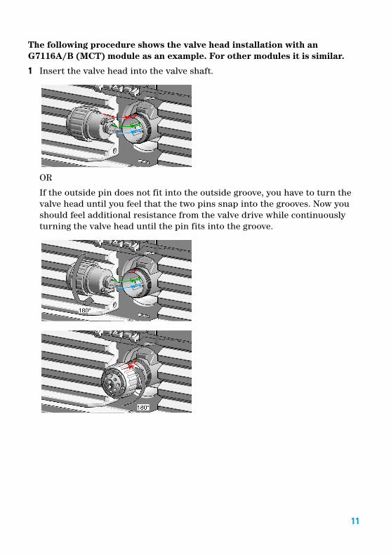
The following procedure shows the valve head installation with an G7116A/B (MCT) module as an example. For other modules it is similar.
1 Insert the valve head into the valve shaft.
OR
If the outside pin does not fit into the outside groove, you have to turn the valve head until you feel that the two pins snap into the grooves. Now you should feel additional resistance from the valve drive while continuously turning the valve head until the pin fits into the groove.
11

2 When the outer pin is locked into the groove, manually screw the nut onto the valve head.
NOTEFasten the nut manually. Do not use any tools.
3 Install all required capillary connections to the valve.
4 Push the valve head until it snaps in and stays in the rear position.
5 Power on or power-cycle your module, so the valve head gets recognized during module initialization.
12

Installing the CapillariesThe 2pos/10port valve can be used here in the same way as a 2pos/6port valve; just follow the re-routing diagram below. The red arrows mean that you have to take the according installation diagram of the 2pos/6port valve but have to mount for example the capillary connected to port 6 of the 2pos/6port valve at port 2 of the 2pos/10port valve. The ports 1 and 8 have to be connected with a high pressure suitable capillary connection (SST, Titanium or PEEK coated SST) and the ports 9 and 10 need to be plugged with Plastic fittings (0100-1259).
Figure 2 Re-routing of 2 position/10 port valve to match 2 position/6 port valve
Installation of Stainless Steel Cladded PEEK CapillariesThe Agilent 1260 Infinity Bio-inert LC System uses PEEK capillaries, which are cladded with stainless steel. These capillaries combine the high pressure stability of steel with the inertness of PEEK. They are used in the high pressure flow path after sample introduction (needle seat capillary) through the column compartment/heat exchangers to the column. Such capillaries need to be installed carefully in order to keep them tight without damaging them by overtightening.
CAUTION Strong force/torque will damage SST cladded PEEK capillaries
➔ Be careful when installing stainless steel cladded PEEK capillaries.
➔ For correct installation see Agilent 1260 Infinity Bio-inert Quaternary LC System Manual.
13

Connecting the Capillaries
Flow DiagramA schematic of the valve flow switching pattern is shown below. The numbered circles represent the ports in the valve stator and stator face assembly. The slots represent the connecting passages in the rotor seal.
The following table gives you an overview about the different connection setups with and without installed Bio-inert Heat Exchanger ( 9 μL internal volume, 600 bar max pressure) (G5616-81000) or Quick-Connect Heat Exchanger Bio-inert (G7116-60041).
14

Table 4 Column regeneration setup (column 1 = left, column 2 = right)
Port Connection without additional heat exchangers
Connection with additional heat exchangers
1 Column 2 inlet ( Capillary PK/ST 0.17 mm x 300 mm RLO/RLO (bio-inert) (G5667-81003))
Right heat exchanger inlet connection (directly or with Capillary PK/ST0.17 mm x 300 mm RLO/RLO (bio-inert) (G5667-81003) connected to bio-inert union)
2 Capillary from Eluent pump / Autosampler Capillary from Eluent pump / Autosampler
3 Column 1 inlet ( Capillary PK/ST 0.17 mm x 300 mm RLO/RLO (bio-inert) (G5667-81003))
Left heat exchanger inlet connection (directly or with Capillary PK/ST 0.17 mm x 300 mm RLO/RLO (bio-inert) (G5667-81003) connected to bio-inert union)
4 Regeneration Pump to valve (Capillary 700 x 0.17 mm ID, titanium (G5611-60501))
Regeneration Pump to valve (Capillary 700 x 0.17 mm ID, titanium (G5611-60501))
5 Connection from Port 5 to Port 10 (Capillary PEEK 0.18 mm x 1.5 m (0890-1763))
Connection from Port 5 to Port 10 (Capillary PEEK 0.18 mm x 1.5 m (0890-1763))
6 Outlet Column 1 to valve (Capillary PEEK 0.18 mm x 1.5 m (0890-1763))
Outlet Column 1 to valve (Capillary PEEK 0.18 mm x 1.5 m (0890-1763))
7 From valve to detector (Capillary PEEK 0.18 mm x 1.5 m (0890-1763))
From valve to detector (Capillary PEEK 0.18 mm x 1.5 m (0890-1763))
8 Outlet Column 2 to valve (Capillary PEEK 0.18 mm x 1.5 m (0890-1763))
Outlet Column 2 to valve (Capillary PEEK 0.18 mm x 1.5 m (0890-1763))
9 Waste (Waste tubing, 2 m (0890-1713)) Waste (Waste tubing, 2 m (0890-1713))
15

Replacement Parts
p/n Description
5068-0040 Stator head assembly
5068-0041 Rotor Seal (PEEK)
5068-0095 Stator face seal
1535-4045 Bearing ring
5068-0059 Stator screws
*G5632-90001**G5632-90001*G5632-90001
Part Number:G5632-90001 Rev. B
Edition: 10/2018Printed in Germany
© Agilent Technologies, Inc2012-2018
Agilent Technologies, IncHewlett-Packard-Strasse 8
76337 Waldbronn, Germany