agilent infiniium 90000 q-series oscilloscopes user’s … · operating procedure, practice, or...
TRANSCRIPT
Notices© Agilent Technologies, Inc. 2008, 2012
No part of this manual may be reproduced in any form or by any means (including electronic storage and retrieval or translation into a foreign language) without prior agreement and written consent from Agilent Technologies, Inc. as governed by United States and international copyright laws.
Manual Part Number
54932-97000
Edition
October 1, 2012
Available in electronic format only
Agilent Technologies, Inc.1900 Garden of the Gods Road Colorado Springs, CO 80907 USA
Warranty
The material contained in this docu-ment is provided “as is,” and is sub-ject to being changed, without notice, in future editions. Further, to the max-imum extent permitted by applicable law, Agilent disclaims all warranties, either express or implied, with regard to this manual and any information contained herein, including but not limited to the implied warranties of merchantability and fitness for a par-ticular purpose. Agilent shall not be liable for errors or for incidental or consequential damages in connection with the furnishing, use, or perfor-mance of this document or of any information contained herein. Should Agilent and the user have a separate written agreement with warranty terms covering the material in this document that conflict with these terms, the warranty terms in the sep-arate agreement shall control.
Technology Licenses
The hardware and/or software described in this document are furnished under a license and may be used or copied only in accordance with the terms of such license.
Restricted Rights Legend
If software is for use in the performance of a U.S. Government prime contract or subcontract, Software is delivered and licensed as “Commercial computer software” as defined in DFAR 252.227-7014 (June 1995), or as a “commercial item” as defined in FAR 2.101(a) or as “Restricted computer software” as defined in FAR 52.227-19 (June 1987) or any equivalent
agency regulation or contract clause. Use, duplication or disclosure of Software is subject to Agilent Technologies’ standard commercial license terms, and non-DOD Departments and Agencies of the U.S. Government will receive no greater than Restricted Rights as defined in FAR 52.227-19(c)(1-2) (June 1987). U.S. Government users will receive no greater than Limited Rights as defined in FAR 52.227-14 (June 1987) or DFAR 252.227-7015 (b)(2) (November 1995), as applicable in any technical data.
Safety Notices
CAUTION
A CAUTION notice denotes a haz-ard. It calls attention to an operat-ing procedure, practice, or the like that, if not correctly performed or adhered to, could result in damage to the product or loss of important data. Do not proceed beyond a CAUTION notice until the indicated conditions are fully understood and met.
WARNING
A WARNING notice denotes a hazard. It calls attention to an operating procedure, practice, or the like that, if not correctly per-formed or adhered to, could result in personal injury or death. Do not proceed beyond a WARNING notice until the indicated condi-tions are fully understood and met.
See also Appendix A, “Safety Notices,” starting on page 83.
Trademarks
Windows® is a trademark or registered trademark of Microsoft Corporation in the United States and/or other countries.
Agilent Infiniium 90000 Q-Series Oscilloscopes User’s Guide 3
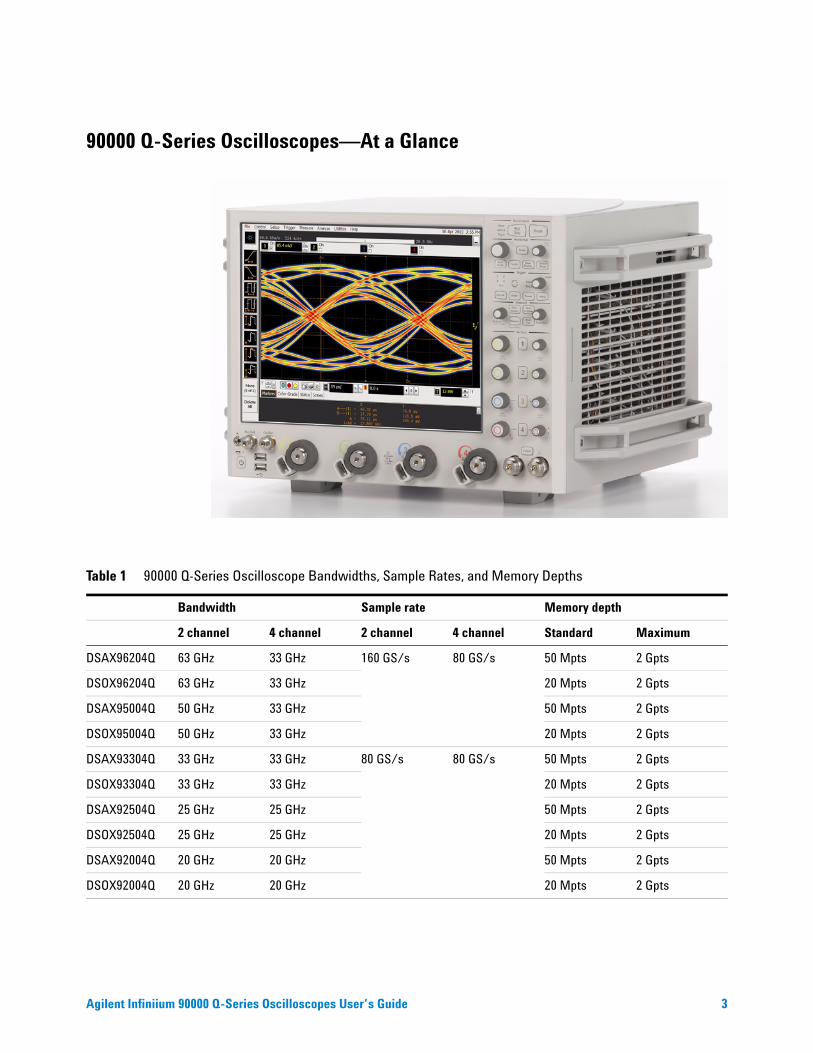
90000 Q-Series Oscilloscopes—At a Glance
Table 1 90000 Q-Series Oscilloscope Bandwidths, Sample Rates, and Memory Depths
Bandwidth Sample rate Memory depth
2 channel 4 channel 2 channel 4 channel Standard Maximum
DSAX96204Q 63 GHz 33 GHz 160 GS/s 80 GS/s 50 Mpts 2 Gpts
DSOX96204Q 63 GHz 33 GHz 20 Mpts 2 Gpts
DSAX95004Q 50 GHz 33 GHz 50 Mpts 2 Gpts
DSOX95004Q 50 GHz 33 GHz 20 Mpts 2 Gpts
DSAX93304Q 33 GHz 33 GHz 80 GS/s 80 GS/s 50 Mpts 2 Gpts
DSOX93304Q 33 GHz 33 GHz 20 Mpts 2 Gpts
DSAX92504Q 25 GHz 25 GHz 50 Mpts 2 Gpts
DSOX92504Q 25 GHz 25 GHz 20 Mpts 2 Gpts
DSAX92004Q 20 GHz 20 GHz 50 Mpts 2 Gpts
DSOX92004Q 20 GHz 20 GHz 20 Mpts 2 Gpts
4 Agilent Infiniium 90000 Q-Series Oscilloscopes User’s Guide
Ease of use with high performance
The Agilent Technologies Infiniium oscilloscopes combine unprecedented ease- of use with high- performance digitizing oscilloscope functionality to simplify your design and analysis measurement tasks.
• Traditional oscilloscope front- panel interface provides direct access to the controls needed for most troubleshooting tasks.
• Graphical user interface with menus, windows, dialogs boxes, and toolbars provides easy access to dozens of configuration and analysis tools, ensuring you can set up and make the most complex measurements.
• All models offer 80 GSa/s sampling rate on all four channels.
• Models with bandwidths from 20 GHz to 63 GHz.
Display shows waveforms and graphical user interface
• Graphical interface allows direct interaction with waveforms, including drag- and- drop positioning and instant waveform zoom.
• Touchscreen display allows oscilloscope operation without an external pointing device.
• Waveforms displayed in color, making correlation easy.
• Current configuration parameters displayed near the waveform display and are colorcoded to make identification easy.
• Graphical interface menus and toolbars simplify complex measurement setups.
Horizontal controls set sweep speed and position
• Intensified waveforms on main sweep window make it easy to see what will appear in the zoom window.
Acquisition and general controls start and stop the oscilloscope and do basic setup
• Run and stop controls for continuous or single acquisitions.
• Clear display before one or more acquisitions.
• Default setup and Autoscale set initial configuration.
Hard disk drive and USB 2.0 port for saving and restoring setups and measurement results
• Store measurement displays for inclusion in reports and test setup guides.
• Store oscilloscope setups to repeat tests another time.
• Hard disk stores oscilloscope operating system.
Agilent Infiniium 90000 Q-Series Oscilloscopes User’s Guide 5
Trigger setup controls set mode and basic parameters
• Select Edge, Glitch, or Advanced Modes.
• Choose input source and slope.
• Use graphical user interface to simplify configuration of pattern, state, delay, and violation trigger modes.
• Use auxiliary trigger to increase triggering flexibility.
Vertical controls set attenuation, and position
• Color- coded knobs make it easy to find the controls that affect each waveform.
Marker and quick measurements help measure waveform parameters
• Waveform markers A and B to check voltage or Δ- time at any point on the displayed waveform.
6 Agilent Infiniium 90000 Q-Series Oscilloscopes User’s Guide
In This Book
This book gives you the information you need to begin using the Infiniium 90000 Q- Series oscilloscopes. It contains four chapters:
Chapter 1, “Setting Up the Oscilloscope,” starting on page 13 contains inspection, power requirements, air flow, and setup information.
Chapter 2, “Working in Comfort,” starting on page 27 contains recommendations for working comfortably and safely while operating the Infiniium oscilloscope.
Chapter 3, “Using the Oscilloscope,” starting on page 31 gives an overview of the front and back panel inputs and outputs, front- panel controls, and graphical user interface, and tells you how to perform basic operations with the oscilloscope.
Chapter 4, “Accessing the Online Help,” starting on page 79 describes the Infiniium oscilloscope application’s online help contents and navigation. The online help describes how to use the Infiniium oscilloscope application in more detail.
For More Information
• For detailed information on how the oscilloscope makes measurements and how to use the oscilloscope, see the Infiniium oscilloscope application’s online help.
• For information on controlling the oscilloscope from a remote computer, see the Oscilloscopes Programmer’s Reference found in the Infiniium oscilloscope application’s online help.
• For information on testing and servicing the oscilloscope, see the Service Guide manual found in the Infiniium oscilloscope application’s online help.
Agilent Infiniium 90000 Q-Series Oscilloscopes User’s Guide 7
Contents90000 Q-Series Oscilloscopes—At a Glance 3
In This Book 6
1 Setting Up the Oscilloscope
To inspect package contents 14
To inspect options and accessories 15
Environmental Conditions 15
To position for proper airflow 16
To connect the mouse, keyboard, and LAN 17
To connect power 18
18
18Power Supply Protection Features 19
To connect oscilloscope probes 19
19
To connect threaded RF cables 21
To tilt the oscilloscope for easier viewing 21
To turn on the oscilloscope 22
To verify basic oscilloscope operation 23
Installing application programs on Infiniium 24
Changing Windows Operating System Settings 25
To turn off the oscilloscope 26
To clean the oscilloscope 26
8 Agilent Infiniium 90000 Q-Series Oscilloscopes User’s Guide
2 Working in Comfort
About Repetitive Strain Injury 28
What is RSI? 28What causes RSI? 28What if I experience discomfort? 28
Mice and Other Input Devices 29
3 Using the Oscilloscope
Front Panel Inputs and Outputs 32
Channel 1-4 Inputs 32RealEdge 1R, 3R Channel Inputs 32Ground 33Aux Out 33Cal Out 33Probe Compensation Terminal 33USB Host Ports 33
Front or Back Panel Inputs and Outputs 34
Trig Out 34Aux Trig 34
Back Panel Inputs and Outputs 35
Motherboard I/O 35USB Device Port 3510 MHz In, 10 MHz Out 36100 MHz In, 100 MHz Out 36
Agilent Infiniium 90000 Q-Series Oscilloscopes User’s Guide 9
Front Panel Controls (Keys and Knobs) 37
Acquisition Run Controls 38To start and stop waveform acquisition 38
Setup and Display Controls 39To set the oscilloscope to a known starting condition 39To clear the waveform display 39To enable or disable the touch screen 40
Horizontal Controls 40To adjust the horizontal scale and horizontal position 40To magnify a part of the waveform using Zoom 41
Vertical Controls 42To turn an analog channel on or off 42To adjust the analog channel’s vertical scale and offset 43
Trigger Controls 43To set the oscilloscope to trigger on an edge 44
Measure Controls 45To use the markers 46To use the quick measurements 46
10 Agilent Infiniium 90000 Q-Series Oscilloscopes User’s Guide
Using the Graphical Interface 48
Graphical User Interface Layout 48Measurement Toolbar 49Tab Display Area 50Waveform Display Area 51Menu Control and Menus 52Horizontal and Trigger Toolbar 52
To perform basic user interface operations 54To select a command from the menu bar 57To select a command from a context-sensitive menu 58To start and stop waveform acquisition 61To clear the waveform display 61To print the screen 62To change waveform brightness 62To turn a channel on or off 63To adjust the vertical offset 63To adjust vertical scaling 65To access the channel setup 66To set the horizontal reference point 67To adjust horizontal scale 68To adjust horizontal position 69To access the horizontal setup 70To zoom on a section of the waveform 71To move the markers using the graphical interface 72To make a measurement on a waveform 73To access the trigger setup 75To set an edge trigger 76To set dialog box preferences 77
Removable Hard Drive 78
78To recover your Infiniium hard disk 78
Infiniium Hard Drive Recovery 78
4 Accessing the Online Help
To access the online help 79
To navigate through the online help 81
To access context-sensitive information 81

Agilent Infiniium 90000 Q-Series Oscilloscopes User’s Guide 11
A Safety Notices
Warnings 83
Safety Symbols 84
Index

12 Agilent Infiniium 90000 Q-Series Oscilloscopes User’s Guide
s1 13
Agilent Infiniium 90000 Q-Series Oscilloscopes User’s Guide
1Setting Up the Oscilloscope
To inspect package contents 14
To inspect options and accessories 15
Environmental Conditions 15
To position for proper airflow 16
To connect power 18
To connect oscilloscope probes 19
To connect oscilloscope probes 19
To connect threaded RF cables 21
To turn on the oscilloscope 22
To verify basic oscilloscope operation 23
Installing application programs on Infiniium 24
Changing Windows Operating System Settings 25
To turn off the oscilloscope 26
To clean the oscilloscope 26
This chapter shows you how to set up your Infiniium oscilloscope, connect power and accessories, and verify general operation.
14 Agilent Infiniium 90000 Q-Series Oscilloscopes User’s Guide
1 Setting Up the Oscilloscope
To inspect package contents
✔ Inspect the shipping container for damage.
Keep a damaged shipping container or cushioning material until you have inspected the contents of the shipment for completeness and have checked the oscilloscope mechanically and electrically.
✔ Inspect the oscilloscope.
• If there is mechanical damage or a defect, or if the oscilloscope does not operate properly or does not pass performance tests, notify your Agilent Technologies Sales Office.
• If the shipping container is damaged, or the cushioning materials show signs of stress, notify the carrier and your Agilent Technologies Sales Office. Keep the shipping materials for the carrier’s inspection. The Agilent Technologies Sales Office will arrange for repair or replacement at Agilent’s option without waiting for claim settlement.
✔ Verify that you received the following items in the Infiniium oscilloscope packaging.
• Infiniium oscilloscope.
• Power cord.
• Keyboard.
• Mouse (USB optical).
• Touchscreen stylus.
• Front panel cover.
• Calibration cable (the 50 GHz and 62 GHz bandwidth models include a second calibration cable for the RealEdge inputs).
• Connector saver adapters (quantity 5 for 20 GHz, 25 GHz, and 33 GHz bandwidth models; additional 2 for 50 GHz and 63 GHz bandwidth models).
• ESD wrist strap.
• Quick Start sheet.
If anything is missing, contact your nearest Agilent Technologies Sales Office. If the shipment was damaged, contact the carrier, then contact the nearest Agilent Technologies Sales Office.
Setting Up the Oscilloscope 1
Agilent Infiniium 90000 Q-Series Oscilloscopes User’s Guide 15
To inspect options and accessories
✔ Verify that you received the options and accessories you ordered and that none were damaged.
If anything is missing, contact your nearest Agilent Technologies Sales Office. If the shipment was damaged, or the cushioning materials show signs of stress, contact the carrier and your Agilent Technologies Sales Office.
For a complete list of options and accessories available for the 90000 Q- Series oscilloscopes, see the Infiniium 90000 Q- Series Oscilloscopes Data Sheet.
Environmental Conditions
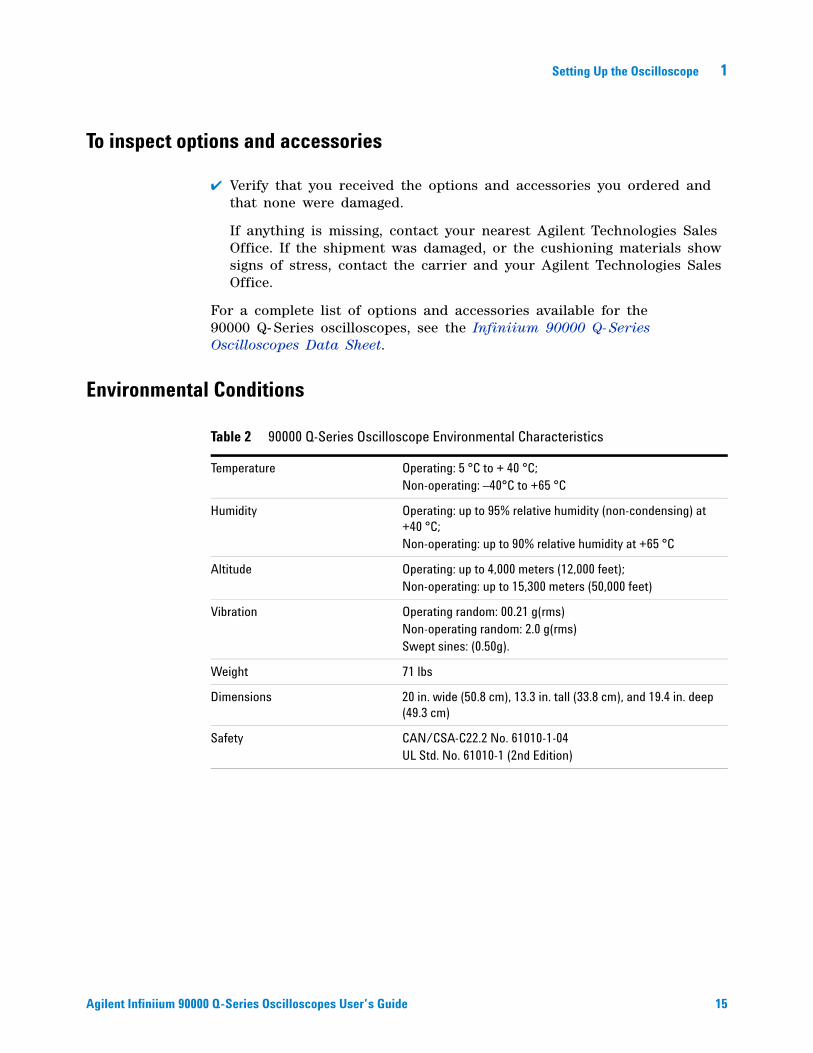
Table 2 90000 Q-Series Oscilloscope Environmental Characteristics
Temperature Operating: 5 °C to + 40 °C;Non-operating: –40°C to +65 °C
Humidity Operating: up to 95% relative humidity (non-condensing) at +40 °C;Non-operating: up to 90% relative humidity at +65 °C
Altitude Operating: up to 4,000 meters (12,000 feet);Non-operating: up to 15,300 meters (50,000 feet)
Vibration Operating random: 00.21 g(rms)Non-operating random: 2.0 g(rms)Swept sines: (0.50g).
Weight 71 lbs
Dimensions 20 in. wide (50.8 cm), 13.3 in. tall (33.8 cm), and 19.4 in. deep (49.3 cm)
Safety CAN/CSA-C22.2 No. 61010-1-04UL Std. No. 61010-1 (2nd Edition)
16 Agilent Infiniium 90000 Q-Series Oscilloscopes User’s Guide
1 Setting Up the Oscilloscope
To position for proper airflow
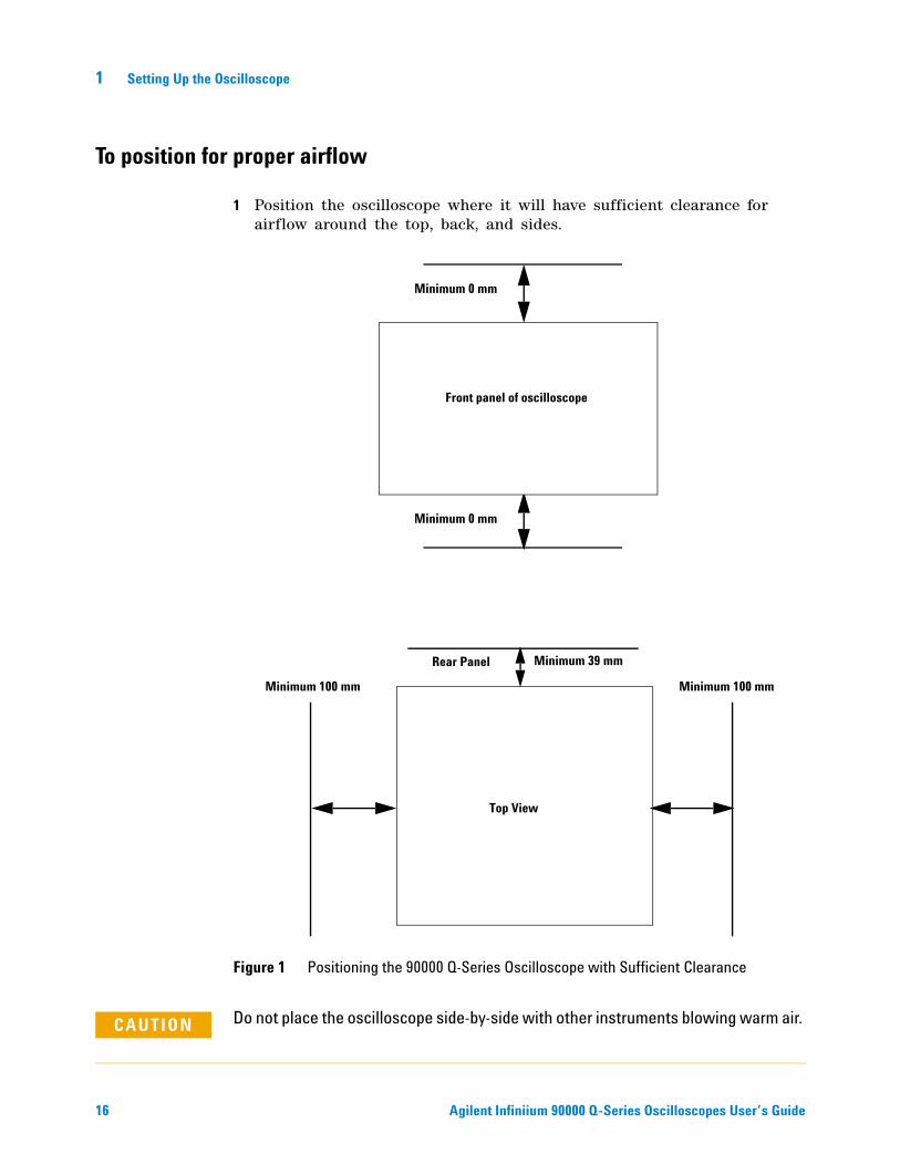
1 Position the oscilloscope where it will have sufficient clearance for airflow around the top, back, and sides.
Figure 1 Positioning the 90000 Q-Series Oscilloscope with Sufficient Clearance
Minimum 0 mm
Minimum 0 mm
Front panel of oscilloscope
Minimum 100 mm Minimum 100 mm
Minimum 39 mm
Top View
Rear Panel
CAUTION Do not place the oscilloscope side-by-side with other instruments blowing warm air.
Setting Up the Oscilloscope 1
Agilent Infiniium 90000 Q-Series Oscilloscopes User’s Guide 17
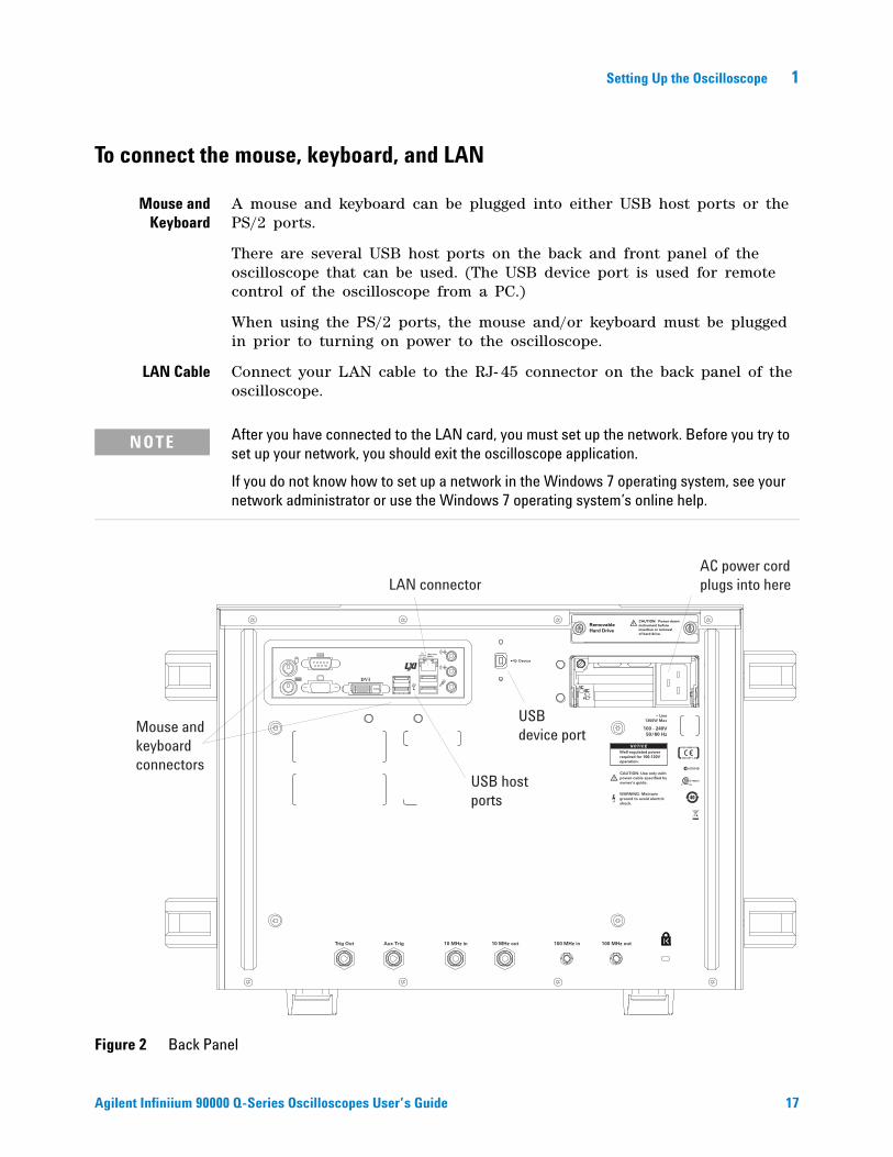
To connect the mouse, keyboard, and LAN
Mouse andKeyboard
A mouse and keyboard can be plugged into either USB host ports or the PS/2 ports.
There are several USB host ports on the back and front panel of the oscilloscope that can be used. (The USB device port is used for remote control of the oscilloscope from a PC.)
When using the PS/2 ports, the mouse and/or keyboard must be plugged in prior to turning on power to the oscilloscope.
LAN Cable Connect your LAN cable to the RJ- 45 connector on the back panel of the oscilloscope.
NOTE After you have connected to the LAN card, you must set up the network. Before you try to set up your network, you should exit the oscilloscope application.
If you do not know how to set up a network in the Windows 7 operating system, see your network administrator or use the Windows 7 operating system’s online help.
Figure 2 Back Panel
(Non Auto-MDIX)
DVI
CAUTION: Power downinstrument beforeinsertion or removalof hard drive.
RemovableHard Drive
N10149
~ Line1350W Max
100 - 240V50/60 Hz
10 MHz inTrig Out 10 MHz out 100 MHz in 100 MHz out
CAUTION: Use only withpower cable specified byowner’s guide.
WARNING: Maintainground to avoid electricshock.
Aux Trig
169323
Device
NOTICEWell-regulated powerrequired for 100-120Voperation.
LAN connector
USB hostports
Mouse andkeyboardconnectors
AC power cordplugs into here
USBdevice port
18 Agilent Infiniium 90000 Q-Series Oscilloscopes User’s Guide
1 Setting Up the Oscilloscope
To connect power
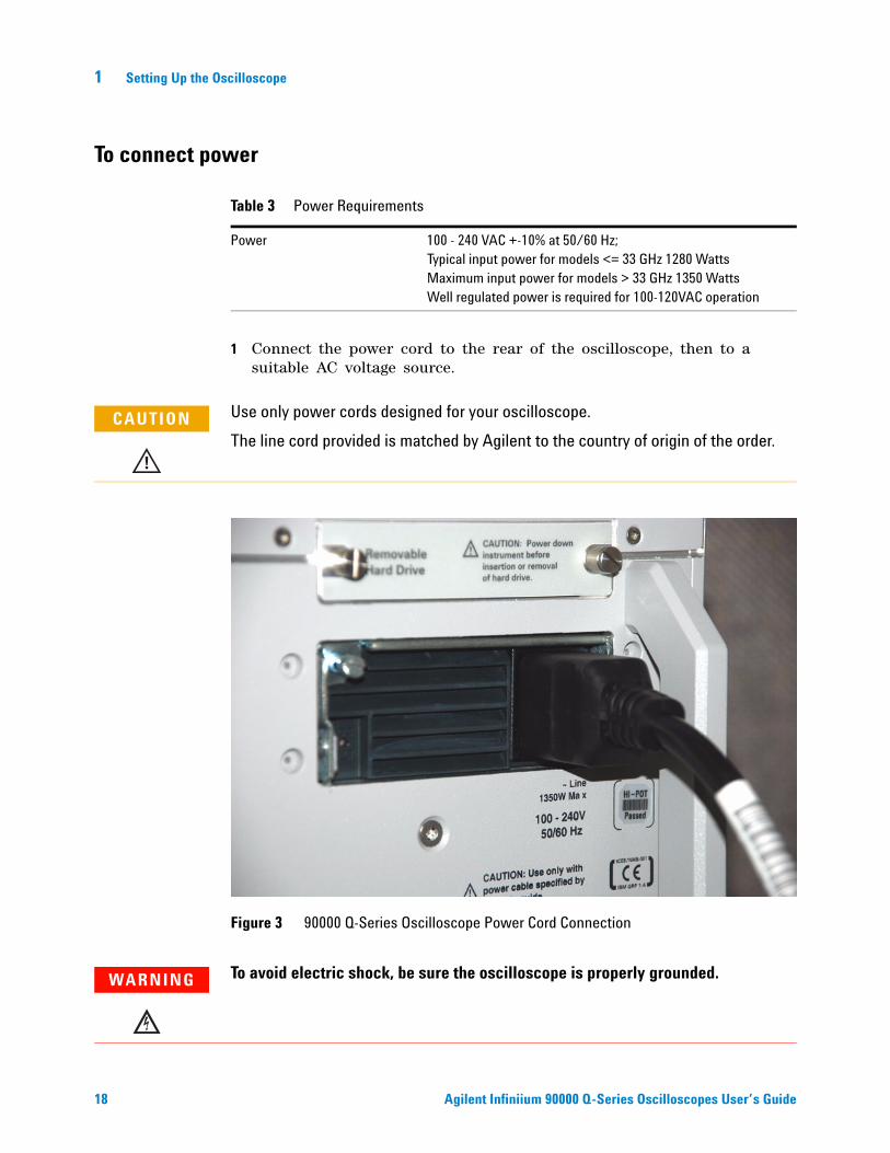
1 Connect the power cord to the rear of the oscilloscope, then to a suitable AC voltage source.
Table 3 Power Requirements
Power 100 - 240 VAC +-10% at 50/60 Hz;Typical input power for models <= 33 GHz 1280 WattsMaximum input power for models > 33 GHz 1350 WattsWell regulated power is required for 100-120VAC operation
CAUTION Use only power cords designed for your oscilloscope.
The line cord provided is matched by Agilent to the country of origin of the order.
Figure 3 90000 Q-Series Oscilloscope Power Cord Connection
WARNING To avoid electric shock, be sure the oscilloscope is properly grounded.
Setting Up the Oscilloscope 1
Agilent Infiniium 90000 Q-Series Oscilloscopes User’s Guide 19
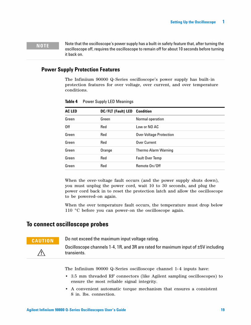
Power Supply Protection Features
The Infiniium 90000 Q- Series oscilloscope’s power supply has built- in protection features for over voltage, over current, and over temperature conditions.
When the over- voltage fault occurs (and the power supply shuts down), you must unplug the power cord, wait 10 to 30 seconds, and plug the power cord back in to reset the protection latch and allow the oscilloscope to be powered- on again.
When the over temperature fault occurs, the temperature must drop below 110 °C before you can power- on the oscilloscope again.
To connect oscilloscope probes
The Infiniium 90000 Q- Series oscilloscope channel 1- 4 inputs have:
• 3.5 mm threaded RF connectors (like Agilent sampling oscilloscopes) to ensure the most reliable signal integrity.
• A convenient automatic torque mechanism that ensures a consistent 8 in. lbs. connection.
NOTE Note that the oscilloscope’s power supply has a built-in safety feature that, after turning the oscilloscope off, requires the oscilloscope to remain off for about 10 seconds before turning it back on.
Table 4 Power Supply LED Meanings
AC LED DC/FLT (Fault) LED Condition
Green Green Normal operation
Off Red Low or NO AC
Green Red Over-Voltage Protection
Green Red Over Current
Green Orange Thermo Alarm Warning
Green Red Fault Over Temp
Green Red Remote On/Off
CAUTION Do not exceed the maximum input voltage rating.
Oscilloscope channels 1-4, 1R, and 3R are rated for maximum input of ±5V including transients.
20 Agilent Infiniium 90000 Q-Series Oscilloscopes User’s Guide
1 Setting Up the Oscilloscope
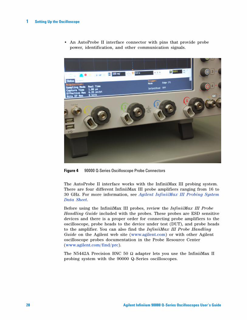
• An AutoProbe II interface connector with pins that provide probe power, identification, and other communication signals.
The AutoProbe II interface works with the InfiniiMax III probing system. There are four different InfiniiMax III probe amplifiers ranging from 16 to 30 GHz. For more information, see Agilent InfiniiMax III Probing System Data Sheet.
Before using the InfiniiMax III probes, review the InfiniiMax III Probe Handling Guide included with the probes. These probes are ESD sensitive devices and there is a proper order for connecting probe amplifiers to the oscilloscope, probe heads to the device under test (DUT), and probe heads to the amplifier. You can also find the InfiniiMax III Probe Handling Guide on the Agilent web site (www.agilent.com) or with other Agilent oscilloscope probes documentation in the Probe Resource Center (www.agilent.com/find/prc).
The N5442A Precision BNC 50 Ω adapter lets you use the InfiniiMax II probing system with the 90000 Q- Series oscilloscopes.
Figure 4 90000 Q-Series Oscilloscope Probe Connectors
Setting Up the Oscilloscope 1
Agilent Infiniium 90000 Q-Series Oscilloscopes User’s Guide 21
To connect threaded RF cables
You can connect threaded RF cables to the Infiniium 90000 Q- Series oscilloscope inputs.
For input channels 1 through 4, you can connect 3.5 mm threaded RF cables, and you can use the automatic torque “clutch” mechanism to ensure a consistent 8 in. lbs. connection.
The Aux Out and Cal Out connectors also work with 3.5 mm threaded RF cables.
For RealEdge input channels 1R and 3R (on the 50 GHz and 62 GHz bandwidth models), you can connect 1.85 mm threaded RF cables, and you will need a torque wrench to apply the necessary 8 in. lbs. of torque.
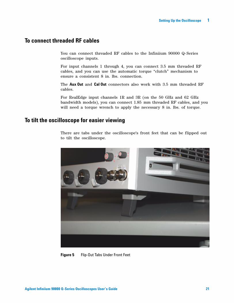
To tilt the oscilloscope for easier viewing
There are tabs under the oscilloscope's front feet that can be flipped out to tilt the oscilloscope.
Figure 5 Flip-Out Tabs Under Front Feet
22 Agilent Infiniium 90000 Q-Series Oscilloscopes User’s Guide
1 Setting Up the Oscilloscope
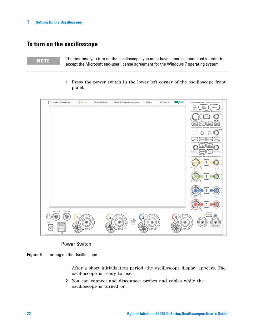
To turn on the oscilloscope
1 Press the power switch in the lower left corner of the oscilloscope front panel.
After a short initialization period, the oscilloscope display appears. The oscilloscope is ready to use.
2 You can connect and disconnect probes and cables while the oscilloscope is turned on.
NOTE The first time you turn on the oscilloscope, you must have a mouse connected in order to accept the Microsoft end-user license agreement for the Windows 7 operating system.
Figure 6 Turning on the Oscilloscope
1R 3R
Aux
Run Control
Horizontal
LevelTrigger
Measure
Vertical
Position Touch Turn
Aux Out Cal Out
for Vernier
Push
Push
to Zero
Pushfor Vernier
Pushto Zero
Push
(Push for 50%)
for Vernier
(Push to Toggle)
(Hold to Reset)
to Zero
Push
MenuSource Slope Sweep
AutoScale
DefaultSetup
ClearDisplay
MultiPurpose
1
2
3
4
RunStop
Single
PrintScreen
Zoom
Touch
ShortCutMarkers
RealEdge
Digital Storage OscilloscopeDSO-X 96204Q 160 GSa/s62 GHz
Power Switch
Setting Up the Oscilloscope 1
Agilent Infiniium 90000 Q-Series Oscilloscopes User’s Guide 23
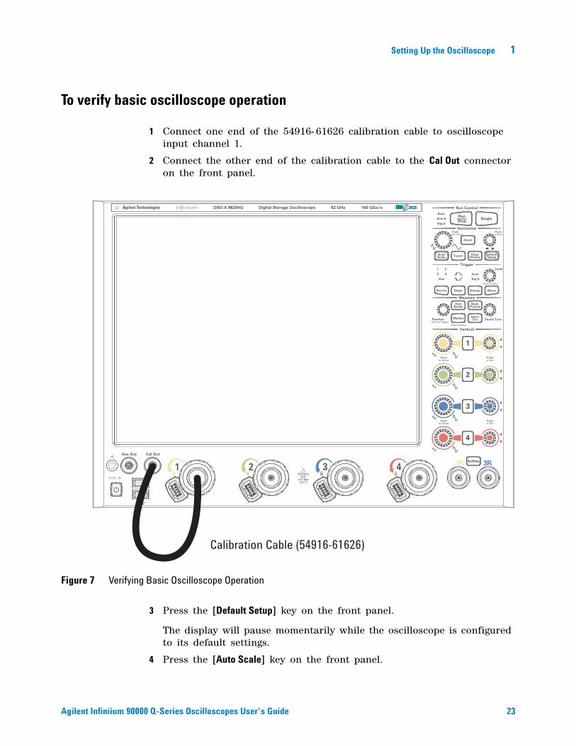
To verify basic oscilloscope operation
1 Connect one end of the 54916- 61626 calibration cable to oscilloscope input channel 1.
2 Connect the other end of the calibration cable to the Cal Out connector on the front panel.
3 Press the [Default Setup] key on the front panel.
The display will pause momentarily while the oscilloscope is configured to its default settings.
4 Press the [Auto Scale] key on the front panel.
Figure 7 Verifying Basic Oscilloscope Operation
1R 3R
Aux
Run Control
Horizontal
LevelTrigger
Measure
Vertical
Position Touch Turn
Aux Out Cal Out
for Vernier
Push
Push
to Zero
Pushfor Vernier
Pushto Zero
Push
(Push for 50%)
for Vernier
(Push to Toggle)
(Hold to Reset)
to Zero
Push
MenuSource Slope Sweep
AutoScale
DefaultSetup
ClearDisplay
MultiPurpose
1
2
3
4
RunStop
Single
PrintScreen
Zoom
Touch
ShortCutMarkers
RealEdge
Digital Storage OscilloscopeDSO-X 96204Q 160 GSa/s62 GHz
Calibration Cable (54916-61626)
24 Agilent Infiniium 90000 Q-Series Oscilloscopes User’s Guide
1 Setting Up the Oscilloscope
The display will pause momentarily while the oscilloscope adjusts the time/div setting and vertical scale. You should then see a square wave with about four cycles on screen and a peak- to- peak amplitude of approximately 4 divisions.
If you do not see the waveform, make sure your power source is adequate, the oscilloscope is properly powered on, and the probe is connected securely to the front- panel channel input and to the probe calibration output.
5 Move the mouse around the mouse surface and verify that the on- screen pointer follows the mouse movement.
6 Touch the pointer of the touch screen stylus to the surface of the screen and move it around while verifying that the pointer follows the movement.
Installing application programs on Infiniium
Infiniium has an open Windows operating system, which lets you install your own application software. Agilent has verified that the following applications are compatible with the Infiniium oscilloscope application.
• Agilent Vector Signal Analysis.
• Agilent VEE Pro.
• Amherst Systems Oscilloscope Tools.
• Microsoft Office.
• MathWorks MATLAB.
• Mathsoft MathCad 2001i.
• McAfee VirusScan.
• Symantec Norton AntiVirus.
If you install an application other than those which Agilent has tested, it is possible that it could break the oscilloscope application. This would potentially require you to recover the oscilloscope hard drive using the hard drive’s hidden recovery partition.
NOTE Before installing any software, you should exit the oscilloscope application.
Setting Up the Oscilloscope 1
Agilent Infiniium 90000 Q-Series Oscilloscopes User’s Guide 25
Changing Windows Operating System Settings
There are many Windows operating system settings that can be changed to suit your own personal preferences. However, there are some operating system settings that you should avoid changing because it will interfere with the proper operation of the oscilloscope.
• Do not change the Power Options.
• Do not change the System Properties Hardware Tab settings.
• Do not change the Regional and Language Options Advanced Tab settings.
• Do not remove Fonts.
• Regarding Display Settings:
• Do not change the screen resolution from 1024 by 768 pixels or the color quality from Highest (32 bit).
• Do not change the Font size to Extra Large.
• Do not use a Menu font size greater than 14 points.
• Do not use the Administrative Tools to enable or disable Internet Information Services (Web Server). Use the Infiniium Web Control dialog box to enable or disable the Web Server.
• Do not delete or modify the Infiniium Administrator user account.
NOTE Before changing any Windows operating system settings outside of the oscilloscope application you should exit the oscilloscope application.
26 Agilent Infiniium 90000 Q-Series Oscilloscopes User’s Guide
1 Setting Up the Oscilloscope
To turn off the oscilloscope
1 Momentarily press the power switch at the lower left corner of the oscilloscope front panel. The oscilloscope will go through a normal Windows operating system shutdown process.
To clean the oscilloscope
• Clean the oscilloscope with a soft cloth dampened with a mild soap and water solution.
CAUTION Do not use too much liquid in cleaning the oscilloscope. Water can enter the Infiniium front panel, damaging sensitive electronic components.

s1 27
Agilent Infiniium 90000 Q-Series Oscilloscopes User’s Guide
2Working in Comfort
About Repetitive Strain Injury 28
Mice and Other Input Devices 29
To optimize your comfort and productivity, it is important that you set up your work area correctly and use your Infiniium oscilloscope properly. With that in mind, we have developed some setup and use recommendations for you to follow based on established ergonomic principles.
Improper and prolonged use of keyboards and input devices are among those tasks that have been associated with repetitive strain injury (RSI) to soft tissues in the hands and arms. If you experience discomfort or pain while using the oscilloscope, discontinue use immediately and consult your physician as soon as possible. For more information on RSI you may wish to consult the “About Repetitive Strain Injury” section, next.
Please study the recommendations offered here in this chapter. Included are references to relevant parts of international standards, regulations, and guidelines, such as ISO 9241 and the European Community Display Screen Equipment directive. You may also wish to consult your employer’s human resources department or other relevant departments for guidance specific to your company.
28 Agilent Infiniium 90000 Q-Series Oscilloscopes User’s Guide
2 Working in Comfort
About Repetitive Strain Injury
Because your comfort and safety are our primary concern, we strongly recommend that you use the Infiniium oscilloscope in accordance with established ergonomic principles and recommendations. Scientific literature suggests that there may be a relationship between injury to soft tissues—especially in the hands and arms—and prolonged improper use of keyboards or other equipment requiring repeated motions of the hands and forearms. This literature also suggests that there are many other risk factors that may increase the chance of such injury, commonly called Repetitive Strain Injury.
What is RSI?
Repetitive Strain Injury (RSI—also known as cumulative trauma disorder or repetitive motion injury) is a type of injury where soft tissues in the body, such as muscles, nerves, or tendons, become irritated or inflamed. RSI has been a reported problem for those who perform repetitive tasks such as assembly line work, meatpacking, sewing, playing musical instruments, and computer work. RSI also has been observed in those who frequently engage in activities such as carpentry, knitting, housework, gardening, tennis, windsurfing and lifting children.
What causes RSI?
The specific causes of RSI have not been established. Nevertheless, the incidence of RSI has been associated with a variety of risk factors, including:
• Too many uninterrupted repetitions of an activity or motion.
• Performing an activity in an awkward or unnatural posture.
• Maintaining static posture for prolonged periods.
• Failing to take frequent short breaks.
• Other environmental and psychosocial factors.
In addition, there have been reports associating the occurrence of RSI with the use of keyboards, mice, and other input devices. Also, certain medical conditions, such as rheumatoid arthritis, obesity, and diabetes, may predispose some people to this type of injury.
What if I experience discomfort?
If you are experiencing any discomfort, seek professional medical advice immediately. Typically, the earlier a problem is diagnosed and treated, the easier it is to resolve.
Working in Comfort 2
Agilent Infiniium 90000 Q-Series Oscilloscopes User’s Guide 29
Mice and Other Input Devices
Various aspects of using mice and other input devices may increase your risk of discomfort or injury. Observing the following recommendations may reduce that risk.
• Try to keep your hand, wrist, and forearm in a neutral position while using your mouse or other input device.
• If you use your thumb to rotate the ball on a trackball or spaceball, keep it in a relaxed, natural shape, and maintain a neutral posture in your hand, wrist, and forearm.
• Hold the mouse gently by draping your fingers over it. Keep your hand relaxed and fingers loose. Do not grip the mouse tightly.
• It takes very little pressure or force from your fingers to activate the buttons or scroll wheel on your mouse, scrolling mouse, trackball, or other input device. Using too much force can place unnecessary stress on the tendons and muscles in your hands, wrists, and forearms.
• If you are using a scrolling mouse, be sure to keep your fingers and hand in a relaxed, neutral position when activating the scroll wheel. Also, this type of mouse features software that can minimize the number of mouse movements or button clicks.
• When using a mouse, trackball, or other input device, position it as close to the keyboard as possible, and keep it at the same level as you do not have to stretch while using it.
• Be sure to keep your mouse and trackball clean. Regular removal of accumulated dust and dirt helps ensure proper tracking and reduces unnecessary hand and wrist motions.

30 Agilent Infiniium 90000 Q-Series Oscilloscopes User’s Guide
2 Working in Comfort
s1 31
Agilent Infiniium 90000 Q-Series Oscilloscopes User’s Guide
3Using the Oscilloscope
Front Panel Inputs and Outputs 32
Front or Back Panel Inputs and Outputs 34
Back Panel Inputs and Outputs 35
Front Panel Controls (Keys and Knobs) 37
Using the Graphical Interface 48
To recover your Infiniium hard disk 78
This chapter tells how to use the Infiniium 90000 Q- Series oscilloscope’s inputs and outputs, front- panel controls, and graphical user interface.
• The familiar front- panel oscilloscope interface with knobs and keys is optimized for common tasks and basic measurements. See “Front Panel Controls (Keys and Knobs)" on page 37.
• The Infiniium oscilloscope application’s graphical interface with menus, windows, dialog boxes, and toolbars provides easy logical access to dozens of configuration and analysis tools, making it easy for you to set up and make the most complex measurements.
The Infiniium oscilloscope application also provides online help, which gives detailed information on using the oscilloscope. See “Using the Graphical Interface" on page 48.
32 Agilent Infiniium 90000 Q-Series Oscilloscopes User’s Guide
3 Using the Oscilloscope
Front Panel Inputs and Outputs
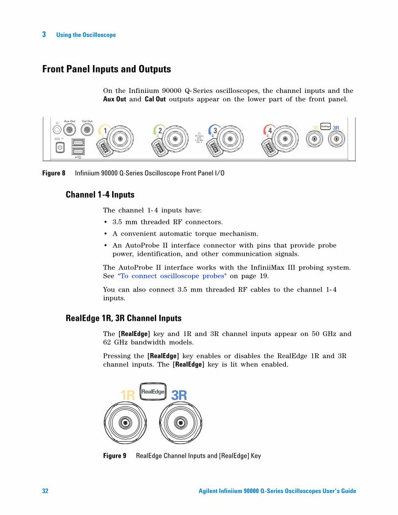
On the Infiniium 90000 Q- Series oscilloscopes, the channel inputs and the Aux Out and Cal Out outputs appear on the lower part of the front panel.
Channel 1-4 Inputs
The channel 1- 4 inputs have:
• 3.5 mm threaded RF connectors.
• A convenient automatic torque mechanism.
• An AutoProbe II interface connector with pins that provide probe power, identification, and other communication signals.
The AutoProbe II interface works with the InfiniiMax III probing system. See “To connect oscilloscope probes" on page 19.
You can also connect 3.5 mm threaded RF cables to the channel 1- 4 inputs.
RealEdge 1R, 3R Channel Inputs
The [RealEdge] key and 1R and 3R channel inputs appear on 50 GHz and 62 GHz bandwidth models.
Pressing the [RealEdge] key enables or disables the RealEdge 1R and 3R channel inputs. The [RealEdge] key is lit when enabled.
Figure 8 Infiniium 90000 Q-Series Oscilloscope Front Panel I/O
1R 3R
Aux Out Cal Out
RealEdge
Figure 9 RealEdge Channel Inputs and [RealEdge] Key
1R 3RRealEdge
Using the Oscilloscope 3
Agilent Infiniium 90000 Q-Series Oscilloscopes User’s Guide 33
When enabled, the RealEdge 1R and 3R channel inputs take over the standard channels 1- 4, except for the trigger circuitry on channels 2 and 4. When RealEdge is enabled, you can still trigger on signals connected to the channel 2 and 4 inputs (but you cannot capture or display data from these signals).
You can connect 1.85 mm threaded RF cables to the RealEdge 1R and 3R channel inputs.
Ground
The ground plug is convenient for ESD wrist straps.
Aux Out
This output signal is selected by the Infiniium oscilloscope application's Calibration Output dialog box. It can be a DC level, the probe compensation signal (a square wave used to adjust compensated passive probes), the trigger out signal, or a demo signal.
Cal Out
This calibration output is used when performing user calibration on the oscilloscope.
A calibration cable is included with the oscilloscope. The 50 GHz and 62 GHz bandwidth models include a second calibration cable for the RealEdge channel inputs.
You can also use the Infiniium oscilloscope application’s Calibration Output dialog box (under the Utilities menu) to select other output signals, just like you can for the Aux Out output.
Probe Compensation Terminal
This terminal has a square wave signal that is used to adjust compensated passive probes.
You can also output a DC level on this terminal using the Infiniium oscilloscope application's Calibration Output dialog box.
USB Host Ports
There are two USB host ports on the front panel, next to the power switch.
34 Agilent Infiniium 90000 Q-Series Oscilloscopes User’s Guide
3 Using the Oscilloscope
Front or Back Panel Inputs and Outputs
These inputs and outputs appear on the back panel in 50 GHz and 62 GHz bandwidth models, and they appear on the front panel in other bandwidth models.
Trig Out
Pulses corresponding to oscilloscope triggers can be sent to this BNC output.
Aux Trig
You can set up the oscilloscope to trigger on the auxiliary trigger signal connected to this BNC input.
Using the Oscilloscope 3
Agilent Infiniium 90000 Q-Series Oscilloscopes User’s Guide 35
Back Panel Inputs and Outputs
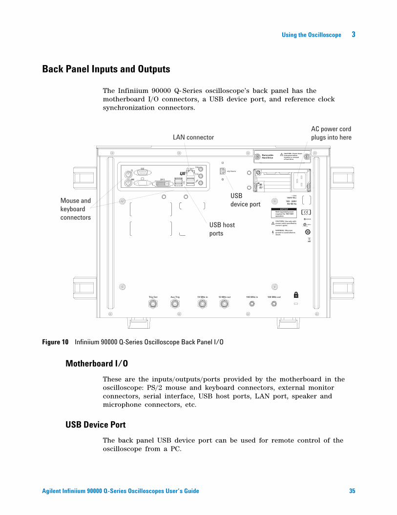
The Infiniium 90000 Q- Series oscilloscope’s back panel has the motherboard I/O connectors, a USB device port, and reference clock synchronization connectors.
Motherboard I/O
These are the inputs/outputs/ports provided by the motherboard in the oscilloscope: PS/2 mouse and keyboard connectors, external monitor connectors, serial interface, USB host ports, LAN port, speaker and microphone connectors, etc.
USB Device Port
The back panel USB device port can be used for remote control of the oscilloscope from a PC.
Figure 10 Infiniium 90000 Q-Series Oscilloscope Back Panel I/O
(Non Auto-MDIX)
DVI
CAUTION: Power downinstrument beforeinsertion or removalof hard drive.
RemovableHard Drive
N10149
~ Line1350W Max
100 - 240V50/60 Hz
10 MHz inTrig Out 10 MHz out 100 MHz in 100 MHz out
CAUTION: Use only withpower cable specified byowner’s guide.
WARNING: Maintainground to avoid electricshock.
Aux Trig
169323
Device
NOTICEWell-regulated powerrequired for 100-120Voperation.
LAN connector
USB hostports
Mouse andkeyboardconnectors
AC power cordplugs into here
USBdevice port
36 Agilent Infiniium 90000 Q-Series Oscilloscopes User’s Guide
3 Using the Oscilloscope
10 MHz In, 10 MHz Out
The 10 MHz In BNC connector is used to synchronize the oscilloscope's horizontal timebase system to a reference clock that you provide. The clock that you provide must meet the following specifications:
• Amplitude: 178 mV peak to 1 V peak.
• Frequency: 10 MHz ±5 ppm high- quality sine wave or square wave.
To use an external reference clock, connect the external clock to the 10 MHz In BNC connector; then, in the Infiniium oscilloscope application's Horizontal Setup dialog box (under Setup > Horizontal...), enable the 10 MHz External Reference Clock.
You can use the 10 MHz Out BNC connector to send the oscilloscope’s 10 MHz reference clock output signal to another instrument’s reference clock input.
100 MHz In, 100 MHz Out
The 100 MHz IN SMA connector is used to synchronize the oscilloscope's horizontal timebase system to a reference clock that you provide. The clock that you provide must meet the following specifications:
• Amplitude: 178 mV peak to 1 V peak.
• Frequency: 100 MHz ±5 ppm high- quality sine wave or square wave.
To use a 100 MHz external reference clock, connect the external clock to the 100 MHz In SMA connector; then, in the Infiniium oscilloscope application's Horizontal Setup dialog box (under Setup > Horizontal...), enable the 100 MHz External Reference Clock.
You can use the 100 MHz Out SMA connector to send the oscilloscope’s 100 MHz reference clock output signal to another instrument’s reference clock input.
Using the Oscilloscope 3
Agilent Infiniium 90000 Q-Series Oscilloscopes User’s Guide 37
Front Panel Controls (Keys and Knobs)
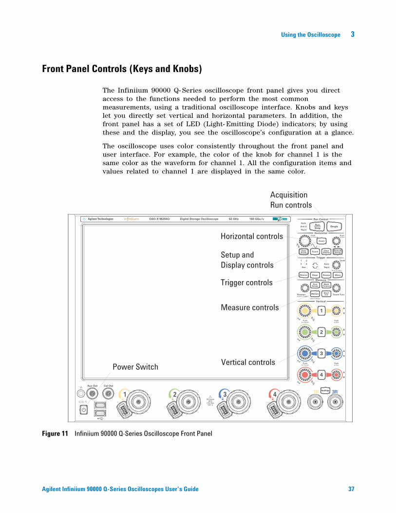
The Infiniium 90000 Q- Series oscilloscope front panel gives you direct access to the functions needed to perform the most common measurements, using a traditional oscilloscope interface. Knobs and keys let you directly set vertical and horizontal parameters. In addition, the front panel has a set of LED (Light- Emitting Diode) indicators; by using these and the display, you see the oscilloscope’s configuration at a glance.
The oscilloscope uses color consistently throughout the front panel and user interface. For example, the color of the knob for channel 1 is the same color as the waveform for channel 1. All the configuration items and values related to channel 1 are displayed in the same color.
Figure 11 Infiniium 90000 Q-Series Oscilloscope Front Panel
1R 3R
Aux
Run Control
Horizontal
LevelTrigger
Measure
Vertical
Position Touch Turn
Aux Out Cal Out
for Vernier
Push
Push
to Zero
Pushfor Vernier
Pushto Zero
Push
(Push for 50%)
for Vernier
(Push to Toggle)
(Hold to Reset)
to Zero
Push
MenuSource Slope Sweep
AutoScale
DefaultSetup
ClearDisplay
MultiPurpose
1
2
3
4
RunStop
Single
PrintScreen
Zoom
Touch
ShortCutMarkers
RealEdge
Digital Storage OscilloscopeDSO-X 96204Q 160 GSa/s62 GHz
Power Switch
Horizontal controls
Trigger controls
AcquisitionRun controls
Measure controls
Vertical controls
Setup andDisplay controls
38 Agilent Infiniium 90000 Q-Series Oscilloscopes User’s Guide
3 Using the Oscilloscope
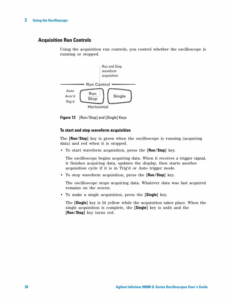
Acquisition Run Controls
Using the acquisition run controls, you control whether the oscilloscope is running or stopped.
To start and stop waveform acquisition
The [Run/Stop] key is green when the oscilloscope is running (acquiring data) and red when it is stopped.
• To start waveform acquisition, press the [Run/Stop] key.
The oscilloscope begins acquiring data. When it receives a trigger signal, it finishes acquiring data, updates the display, then starts another acquisition cycle if it is in Trig’d or Auto trigger mode.
• To stop waveform acquisition, press the [Run/Stop] key.
The oscilloscope stops acquiring data. Whatever data was last acquired remains on the screen.
• To make a single acquisition, press the [Single] key.
The [Single] key is lit yellow while the acquisition takes place. When the single acquisition is complete, the [Single] key is unlit and the [Run/Stop] key turns red.
Figure 12 [Run/Stop] and [Single] Keys
Run Control
Horizontal
RunStop
Single
Run and Stopwaveformacquisition
Using the Oscilloscope 3
Agilent Infiniium 90000 Q-Series Oscilloscopes User’s Guide 39
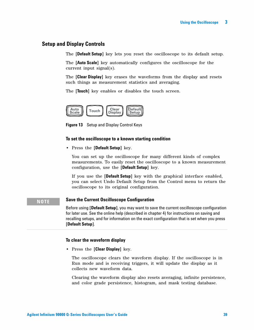
Setup and Display Controls
The [Default Setup] key lets you reset the oscilloscope to its default setup.
The [Auto Scale] key automatically configures the oscilloscope for the current input signal(s).
The [Clear Display] key erases the waveforms from the display and resets such things as measurement statistics and averaging.
The [Touch] key enables or disables the touch screen.
To set the oscilloscope to a known starting condition
• Press the [Default Setup] key.
You can set up the oscilloscope for many different kinds of complex measurements. To easily reset the oscilloscope to a known measurement configuration, use the [Default Setup] key.
If you use the [Default Setup] key with the graphical interface enabled, you can select Undo Default Setup from the Control menu to return the oscilloscope to its original configuration.
To clear the waveform display
• Press the [Clear Display] key.
The oscilloscope clears the waveform display. If the oscilloscope is in Run mode and is receiving triggers, it will update the display as it collects new waveform data.
Clearing the waveform display also resets averaging, infinite persistence, and color grade persistence, histogram, and mask testing database.
Figure 13 Setup and Display Control Keys
AutoScale
DefaultSetup
ClearDisplayTouch
NOTE Save the Current Oscilloscope Configuration
Before using [Default Setup], you may want to save the current oscilloscope configuration for later use. See the online help (described in chapter 4) for instructions on saving and recalling setups, and for information on the exact configuration that is set when you press [Default Setup].
40 Agilent Infiniium 90000 Q-Series Oscilloscopes User’s Guide
3 Using the Oscilloscope
To enable or disable the touch screen
• To enable or disable the touch screen, press the front panel [Touch] key.
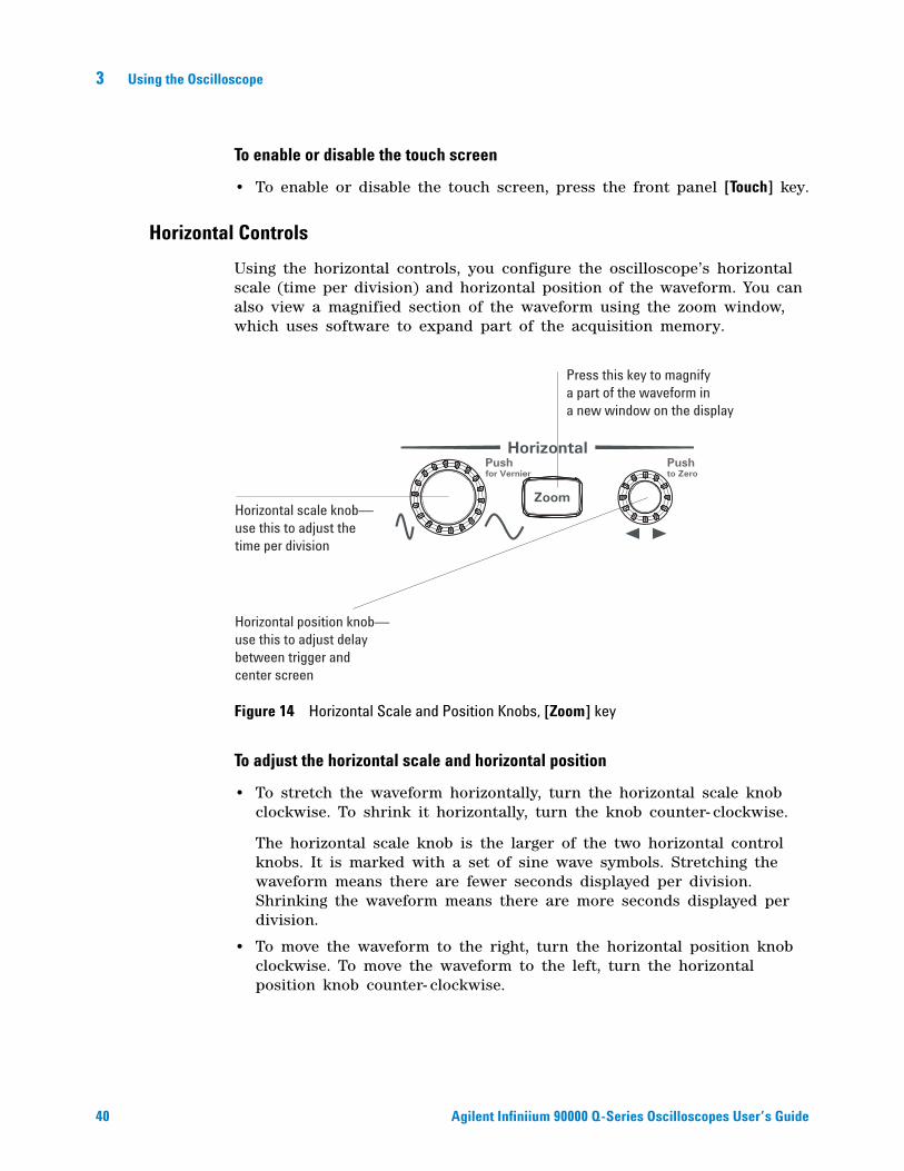
Horizontal Controls
Using the horizontal controls, you configure the oscilloscope’s horizontal scale (time per division) and horizontal position of the waveform. You can also view a magnified section of the waveform using the zoom window, which uses software to expand part of the acquisition memory.
To adjust the horizontal scale and horizontal position
• To stretch the waveform horizontally, turn the horizontal scale knob clockwise. To shrink it horizontally, turn the knob counter- clockwise.
The horizontal scale knob is the larger of the two horizontal control knobs. It is marked with a set of sine wave symbols. Stretching the waveform means there are fewer seconds displayed per division. Shrinking the waveform means there are more seconds displayed per division.
• To move the waveform to the right, turn the horizontal position knob clockwise. To move the waveform to the left, turn the horizontal position knob counter- clockwise.
Figure 14 Horizontal Scale and Position Knobs, [Zoom] key
HorizontalPushfor Vernier
Pushto Zero
ZoomHorizontal scale knob—use this to adjust thetime per division
Horizontal position knob—use this to adjust delaybetween trigger andcenter screen
Press this key to magnifya part of the waveform ina new window on the display
Using the Oscilloscope 3
Agilent Infiniium 90000 Q-Series Oscilloscopes User’s Guide 41
Moving the waveform to the right shows more of the pre- trigger data (data acquired before the trigger event). Moving the waveform to the left shows more of the post- trigger data (data acquired after the trigger event).
The horizontal position knob is the smaller of the two horizontal control knobs. It is marked with a set of arrows. There is a detent programmed into the software so there is a momentary pause at zero while you are turning the knob. Continuing to turn the knob will move the horizontal position through zero.
To magnify a part of the waveform using Zoom
• To turn on zoom, press the [Zoom] key. To turn it off, press the [Zoom] key again.
The waveform display area splits into two regions. The top one is the main timebase. The bottom is the zoomed timebase, which represents a software expansion of the acquired waveform data. A section of the waveform in the main sweep window is highlighted to indicate the part shown in the delayed sweep window.
The horizontal scale and horizontal position controls now change how the waveform is shown in the delayed sweep window. The horizontal scale will change the amount of magnification, while the position will change the part of the waveform in the main window that is shown in the Zoomed window.
42 Agilent Infiniium 90000 Q-Series Oscilloscopes User’s Guide
3 Using the Oscilloscope
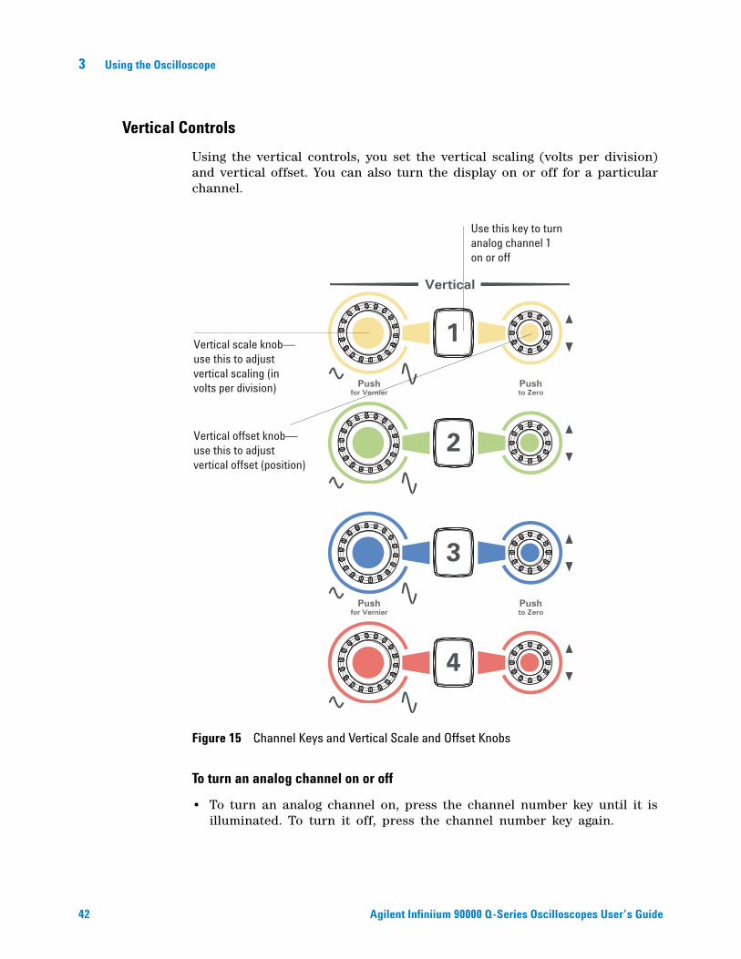
Vertical Controls
Using the vertical controls, you set the vertical scaling (volts per division) and vertical offset. You can also turn the display on or off for a particular channel.
To turn an analog channel on or off
• To turn an analog channel on, press the channel number key until it is illuminated. To turn it off, press the channel number key again.
Figure 15 Channel Keys and Vertical Scale and Offset Knobs
Vertical
for Vernier
Push
Push
to Zero
Push
for Vernier
to Zero
Push
1
2
3
4
Use this key to turnanalog channel 1on or off
Vertical scale knob—use this to adjustvertical scaling (involts per division)
Vertical offset knob—use this to adjustvertical offset (position)
Using the Oscilloscope 3
Agilent Infiniium 90000 Q-Series Oscilloscopes User’s Guide 43
If you are not using a particular analog channel, you can turn it off. This simplifies the waveform display and also increases the display update rate. While a analog channel is turned off, data acquisition continues for that channel. Therefore, you can still use the analog channel as a source for functions.
To adjust the analog channel’s vertical scale and offset
• To make the waveform bigger, turn the vertical scale knob clockwise. To make it smaller, turn the knob counter- clockwise.
The vertical scale knob is the larger of the two knobs for a channel. It is marked with a set of sine wave symbols. Decreasing the vertical scale makes the waveform bigger. There are fewer volts displayed per division. Increasing the vertical scale makes the waveform smaller. There are more volts displayed per division.
• To move the waveform toward the top of the display, turn the vertical offset knob clockwise. To move it toward the bottom of the display, turn the knob counter- clockwise.
The vertical offset knob is the smaller of the two knobs for a channel. It is marked with a set of arrows.
Trigger Controls
Using the trigger controls, you set the conditions on which the oscilloscope will trigger and acquire an input signal. You can set up a variety of trigger conditions. Edge triggers can be selected from the front panel, and the parameters for edge triggering can be set up here as well.
Trigger configuration settings you make using the graphical interface are reflected in the front- panel status indicators, and will remain set unless you change them (either using the front panel or the graphical interface) or press the [Default Setup] key. See “Using the Graphical Interface" on page 48 for information on accessing the graphical interface.
NOTE Using an Analog Channel as External Trigger
Any analog channel can be used as a trigger source. If you need an external trigger but do not need all analog channels, you can use an analog channel as an external trigger without displaying it by turning the analog channel display off.
44 Agilent Infiniium 90000 Q-Series Oscilloscopes User’s Guide
3 Using the Oscilloscope
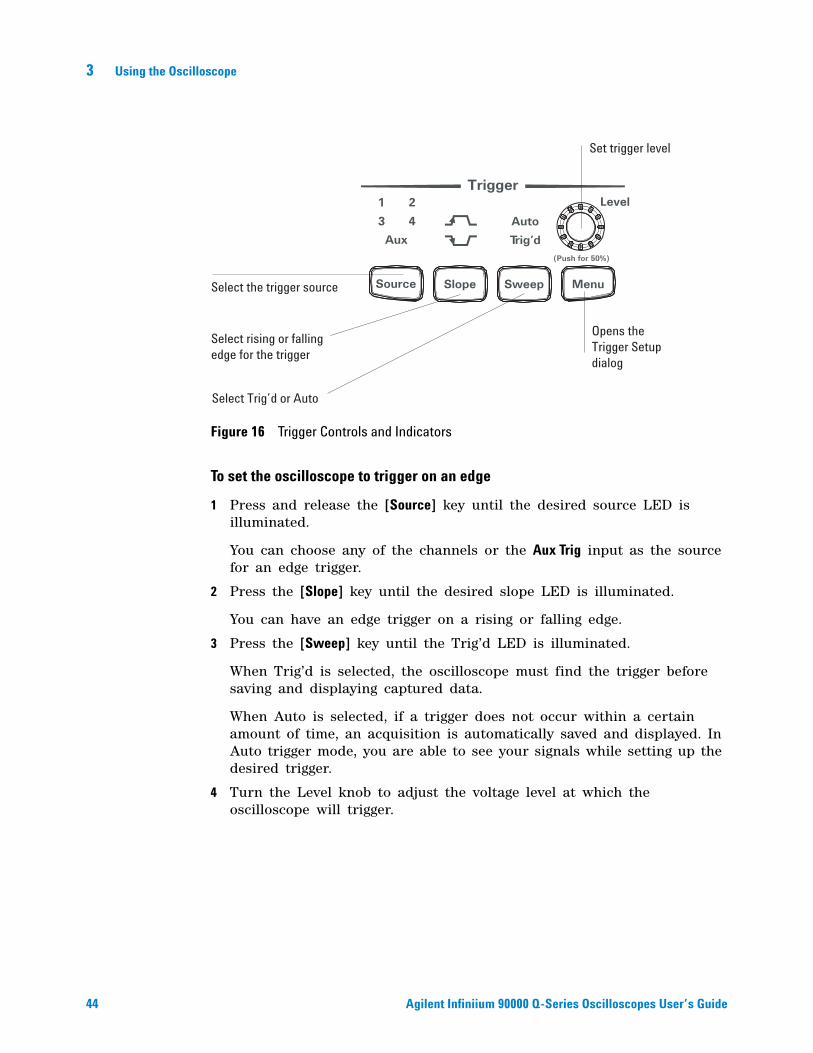
To set the oscilloscope to trigger on an edge
1 Press and release the [Source] key until the desired source LED is illuminated.
You can choose any of the channels or the Aux Trig input as the source for an edge trigger.
2 Press the [Slope] key until the desired slope LED is illuminated.
You can have an edge trigger on a rising or falling edge.
3 Press the [Sweep] key until the Trig’d LED is illuminated.
When Trig’d is selected, the oscilloscope must find the trigger before saving and displaying captured data.
When Auto is selected, if a trigger does not occur within a certain amount of time, an acquisition is automatically saved and displayed. In Auto trigger mode, you are able to see your signals while setting up the desired trigger.
4 Turn the Level knob to adjust the voltage level at which the oscilloscope will trigger.
Figure 16 Trigger Controls and Indicators
Aux
LevelTrigger
(Push for 50%)
MenuSource Slope SweepSelect the trigger source
Select rising or fallingedge for the trigger
Set trigger level
Select Trig’d or Auto
Opens theTrigger Setupdialog
Using the Oscilloscope 3
Agilent Infiniium 90000 Q-Series Oscilloscopes User’s Guide 45
Measure Controls
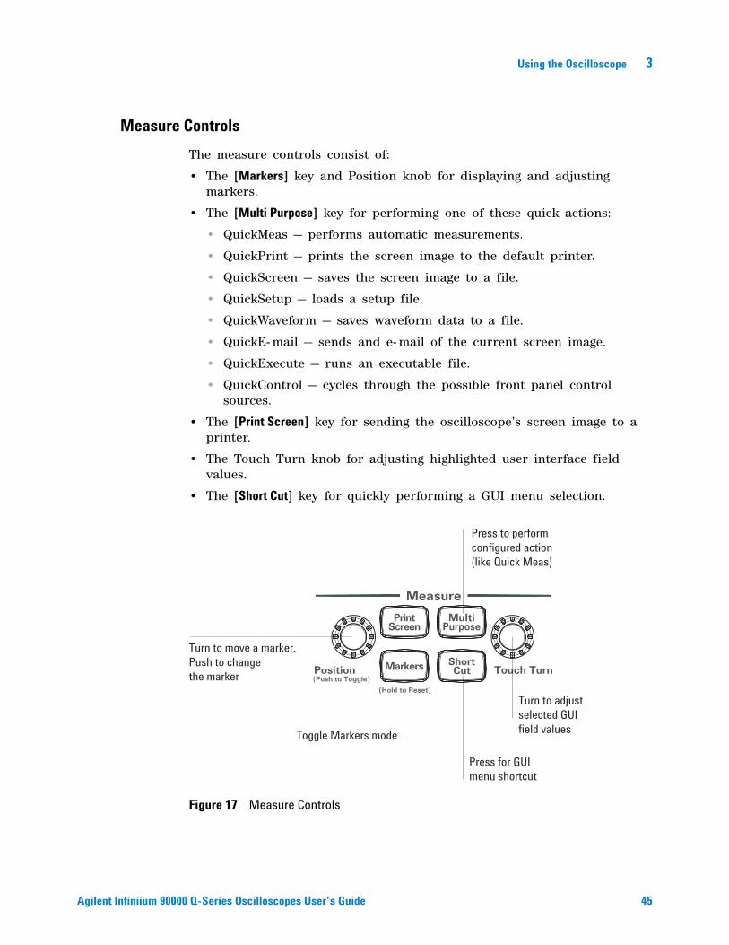
The measure controls consist of:
• The [Markers] key and Position knob for displaying and adjusting markers.
• The [Multi Purpose] key for performing one of these quick actions:
• QuickMeas — performs automatic measurements.
• QuickPrint — prints the screen image to the default printer.
• QuickScreen — saves the screen image to a file.
• QuickSetup — loads a setup file.
• QuickWaveform — saves waveform data to a file.
• QuickE- mail — sends and e- mail of the current screen image.
• QuickExecute — runs an executable file.
• QuickControl — cycles through the possible front panel control sources.
• The [Print Screen] key for sending the oscilloscope’s screen image to a printer.
• The Touch Turn knob for adjusting highlighted user interface field values.
• The [Short Cut] key for quickly performing a GUI menu selection.
Figure 17 Measure Controls
Measure
Position Touch Turn(Push to Toggle)
(Hold to Reset)
MultiPurpose
PrintScreen
ShortCutMarkers
Turn to move a marker,Push to changethe marker
Press for GUImenu shortcut
Toggle Markers mode
Press to performconfigured action(like Quick Meas)
Turn to adjustselected GUIfield values
46 Agilent Infiniium 90000 Q-Series Oscilloscopes User’s Guide
3 Using the Oscilloscope
To use the markers
Markers make it easier to make precise measurements because the marker measurement readouts show exact voltage and time positions for the markers. The measurements are based on actual waveform data from the acquisition system, not on approximations based on the display position, so you can be sure that the values are highly accurate.
Using the marker and measurement controls, you control two sets of markers within the oscilloscope graticule. You use markers to make more accurate measurements of waveform events than you could make visually.
Both time and voltage differences between the markers are updated continuously on the screen. By default, the markers track the source waveform. Voltage measurements from the markers are the value of the waveform at the time set with the marker arrow keys.
• To select the type of marker mode that you want to use, press the [Markers] key until the mode appears in the pop- up dialog box.
• To turn on Marker A, push the Position knob until the marker that you want to move appears in the pop- up dialog box.
Marker A has a solid line pattern on the waveform display. It is associated with the first available source on the display.
• To turn on Marker B, push the Position knob until the marker that you want to move appears in the pop- up dialog box.
Marker B has a dashed line pattern on the waveform display. It is associated with the first available source on the display.
• To move a marker, turn the Position knob.
In Measurement Marker mode, the marker position cannot be changed.
To use the quick measurements
The action taken when the [Multi Purpose] key is pressed depends on the feature selected in the Customize Multipurpose dialog box. The default feature is QuickMeas (quick measurements), which is described as follows.
• To turn on the quick measurement display, press the [Multi Purpose] key.
The five preset measurements defined in the Quick Measurement configuration are enabled and results are displayed on the screen for the first waveform source. The factory default measurements are: Vp- p, Period, Frequency, Rise time, and Fall time.
• To measure parameters for another waveform, press the [Multi Purpose] key until that waveform is the one shown in the measurement readout.
Continuing to press the [Multi Purpose] key cycles through each of the waveforms available.
Using the Oscilloscope 3
Agilent Infiniium 90000 Q-Series Oscilloscopes User’s Guide 47
• To turn off the quick measurement display, press and release the [Multi Purpose] key until the measurements are turned off.
The measurement results disappear from the screen.
See the Infiniium oscilloscope application’s online help (described in Chapter 4) for information on how to configure the quick measurement capability, using the Customize Measurement feature of the graphical interface.
48 Agilent Infiniium 90000 Q-Series Oscilloscopes User’s Guide
3 Using the Oscilloscope
Using the Graphical Interface
With the graphical interface for the Infiniium oscilloscope, you can access all the configuration and measurement features of the oscilloscope through an easy- to- use system of menus, tool bars, dialog boxes, icons, and buttons.
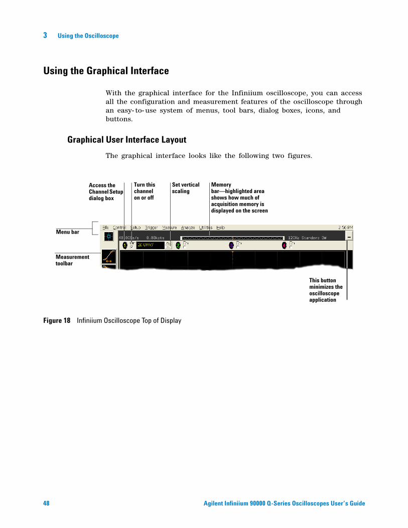
Graphical User Interface Layout
The graphical interface looks like the following two figures.
Figure 18 Infiniium Oscilloscope Top of Display
Menu bar
Measurement toolbar
Set vertical scaling
Turn this channel on or off
Access the Channel Setup dialog box
Memory bar—highlighted area shows how much of acquisition memory is displayed on the screen
This button minimizes the oscilloscope application
Using the Oscilloscope 3
Agilent Infiniium 90000 Q-Series Oscilloscopes User’s Guide 49
To make it easy to see which controls affect each waveform, the oscilloscope uses color consistently throughout the graphical interface. These colors match the ones used on the front- panel channel inputs. For example, the color of the waveform for channel 1 matches the color for that channel. If channel 1 is the trigger signal, all of the trigger configuration items, including the trigger level reference icon (at the right side of the waveform display area), will match that color. The buttons associated with that channel, vertical scaling and offset settings, ground reference indicator, and measurements done on that channel also have the same color.
The graphical interface is arranged so that the most common functions affecting the waveform display are located around the edge of the waveform viewing area. These include the measurement toolbar, horizontal and trigger toolbar, and vertical toolbar.
Measurement Toolbar
The measurement toolbar contains icons representing the most commonly used automatic measurements built into the oscilloscope.
Drag and Drop Measurements By dragging one of the measurement icons to a waveform in the waveform display area, you can make that measurement on the waveform. As you drag a measurement icon around the screen, the icon outline changes color to match the color of the closest waveform. This makes it easy to see which waveform will be measured when you drop the
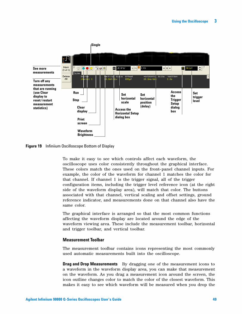
Figure 19 Infiniium Oscilloscope Bottom of Display
Set trigger level
Set horizontal scale
Run
Turn off any measurements that are running (use Clear display to reset/restart measurement statistics)
Set horizontal position (delay)
Stop
Clear display
See more measurements
Access the Horizontal Setup dialog box
Access the Trigger Setup dialog box
Print screen
Waveform Brightness
Single
50 Agilent Infiniium 90000 Q-Series Oscilloscopes User’s Guide
3 Using the Oscilloscope
icon. For those measurements that are done on waveform features, the measurement is made at the feature closest to the location where you dropped the icon. For example, you might want to measure the rise time of the fifth rising edge; dropping the rise time measurement icon at that edge will cause the measurement to be made on that edge.
You can also make a measurement by simply clicking the icon on the measurement toolbar, then selecting the source to be measured in the dialog box that appears. When you start a measurement this way, any measurements on waveform- specific features will measure the feature closest to the horizontal reference indicator.
Each waveform can have multiple simultaneous measurements and the measurements can all be of the same type, if desired. For example, you can have three pulse width measurements on different parts of the same waveform.
Geometric Measurement Indicators For each measurement currently running, a geometric indicator at the measurement location on the waveform corresponds to an identical indicator in the measurement results readout. This makes it easy for you to verify that the readout shows results for the correct waveform and the correct feature on that waveform. See Figure 41 for an example.
Tool Tips To find out what a particular measurement tool does, move the mouse pointer over it for a moment. A small popup will appear that describes the measurement.
Other Measurement Features There are more measurements available than will fit on a single toolbar. Click the More (1 of 2) or More (2 of 2) icons to see other measurements. Clicking Clear All will remove all selected measurements from the waveform display area.
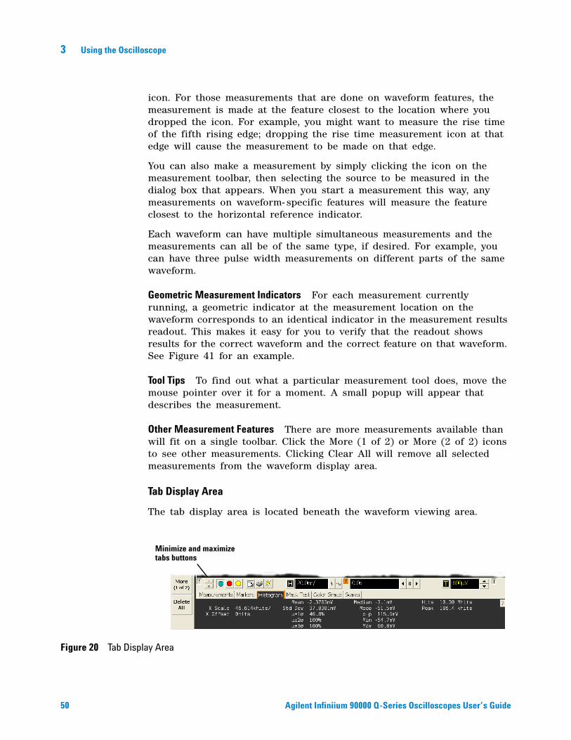
Tab Display Area
The tab display area is located beneath the waveform viewing area.
Figure 20 Tab Display Area
Minimize and maximize tabs buttons
Using the Oscilloscope 3
Agilent Infiniium 90000 Q-Series Oscilloscopes User’s Guide 51
The display area shows information and statistics for the particular tab that is selected. The type of markers that are shown in the waveform viewing area depend on the tab that you have selected. The selected tab has an orange border to reflect the type of markers being displayed. For example, when the Histogram tab is selected, the markers are histogram markers and are used to define the histogram window.
Waveform Display Area
The waveform display area shows the waveforms, and optionally, the results of your measurements. Several display options, including a grid, are available and can be configured using the graphical interface.
Waveform Manipulation When using the graphical interface, two features are available that can simplify your work with waveforms:
• Direct Manipulation — you can use the mouse to click and drag waveforms to new vertical positions, which changes the vertical offset, or to new horizontal positions, which changes the horizontal position or delay value.
• Zoom — you can click and drag a rectangular area on the display, then click the Waveform Zoom menu item to zoom on that section of displayed waveforms. The oscilloscope does this in one of two ways. If acquisition is stopped, the magnification is done by the oscilloscope software. If acquisition is running, the oscilloscope automatically adjusts the vertical scaling and offset and the horizontal scale and position to present the zoomed section of the waveforms.
See “To zoom on a section of the waveform” on page 71.
Ground Reference Indicators A small symbol is shown at the right side of the waveform display area for each waveform that is on, including channels, waveform memories, and functions. This symbol represents the ground reference point for each channel; it moves when you change the vertical offset. You can also drag this symbol up and down using the mouse or touch screen; doing so automatically changes the vertical offset for that waveform.
NOTE Avoid Overdriving Vertical Input Amplifiers
When zooming on a waveform with the oscilloscope running, be careful to keep the signal within the screen vertically to avoid overdriving the vertical input amplifiers. Overdriving causes waveform distortion and erroneous measurement results.
52 Agilent Infiniium 90000 Q-Series Oscilloscopes User’s Guide
3 Using the Oscilloscope
Menu Control and Menus
The display looks like Figure 18 and Figure 19, including a menu bar, measurement toolbar (if enabled), and graphical controls for vertical, horizontal, trigger, and acquisition.
You can use the menu bar for most oscilloscope configuration functions. Context- sensitive menus, which pop up to provide a selection of commands within particular regions of the user interface, are available in the following regions:
• Memory bar.
• Waveform display area.
• Measurement toolbar.
• Horizontal and acquisition controls.
You display a context- sensitive menu by clicking the right mouse button with the pointer in one of these regions. For more information on context- sensitive menus, see “To select a command from a context- sensitive menu" on page 58.
Vertical Settings and Controls The top of the waveform display area includes the vertical settings and controls. All channels are shown with the corresponding vertical scaling settings in volts per division. Each has a checkbox allowing you to turn that channel on or off, and a set of controls allowing you to change the vertical scaling. Clicking directly on the vertical scaling value displays a pop- up numeric keypad allowing you to set a precise vertical scale.
Horizontal and Trigger Toolbar
At the bottom of the waveform display area is the horizontal and trigger toolbar. This toolbar includes the run/stop controls, the horizontal controls, and the trigger controls.
Run/Stop Control See Figure 19. At the left side of the Horizontal and Trigger toolbar are six icons:
• The leftmost is a blue- green octagon. Clicking this starts an acquisition. (Same as pressing the [Run] key on the front panel.)
• The next control is a red octagon. Clicking this stops acquisition. (Same as pressing the [Stop] key on the front panel.)
• The next control is a yellow octagon. Clicking this starts a single acquisition. (Same as pressing the [Single] key on the front panel.)
• The next control is a small windshield wiper. Clicking this clears acquired waveform data from the display. (Same as pressing the [Clear Display] key on the front panel.)
Using the Oscilloscope 3
Agilent Infiniium 90000 Q-Series Oscilloscopes User’s Guide 53
• The next control is a printer. Clicking prints the screen to the default printer.
• The rightmost control is the waveform brightness control.
Horizontal settings and controls The middle of the Horizontal and Trigger toolbar contains the horizontal settings and controls. Leftmost is a button, labeled with an “H.” Clicking this displays the horizontal setup dialog box.
Next is the current horizontal scale. Clicking this displays a pop- up numeric keypad so you can set a particular horizontal scale. Or, you can click the two icons to the right of the horizontal scale setting to cycle through the preset speeds. The left icon shrinks the waveform, which decreases the horizontal scale and increases the time per division. The right icon stretches the waveform, which increases the horizontal scale and decreases the time per division.
Next is the horizontal position (delay) setting. Clicking this displays a pop- up numeric keypad that lets you set a particular position. Or, you can use the three icons to the right. The left arrow moves the waveform to the left, the center “0” resets the delay to zero, and the right arrow moves the waveform to the right.
Across the toolbar are three vertical arrows. These are the left, center, and right horizontal reference indicators. Clicking one of these arrows moves the horizontal position to the respective horizontal reference position on the display—left, center, or right. Assuming the horizontal position is at zero:
• Left means the information on the display is all post- trigger.
• Center means the information to the left of center is pretrigger; to the right is post- trigger.
• Right means the information on the display is pretrigger.
The horizontal position value represents the time relative to the trigger at the respective horizontal reference. When you change the horizontal scale, the waveforms expand and contract about this reference position.
Trigger settings and controls The right side of the Horizontal and Trigger toolbar contains the trigger settings and controls. These will vary depending on the current trigger configuration, which can be set using the front panel and the graphical interface. Advanced trigger configuration items are available only through the graphical interface. You can click the button labeled with a “T” to bring up the trigger setup dialog box.
When the scope is set for edge trigger on a particular channel, the trigger level setting is shown. You can click it to display a pop- up numeric keypad that lets you set a particular trigger level. You can also click the up and down arrows to the right of the setting to increase or decrease the trigger
54 Agilent Infiniium 90000 Q-Series Oscilloscopes User’s Guide
3 Using the Oscilloscope
level, respectively. You can also click the trigger reference indicator at the right side of the display and drag it up or down to change the trigger level.
To perform basic user interface operations
• To move the pointer on the screen, move the mouse or touch the screen with the stylus and move it.
• To click an item in the graphical interface, point at that item with the pointer, then press and release the left mouse button or touch screen.
• To right- click an item in the graphical interface, point at that item with the mouse pointer, then press and release the right mouse button. The right mouse button capability is not available using the touch screen stylus.
Use the right- click operation to access context- sensitive menus. See “To select a command from a context- sensitive menu” on page 58.
• To use a option button, click to select the desired item.
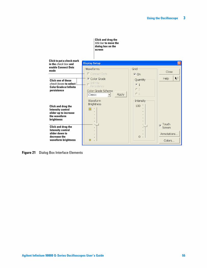
Option buttons appear in many different dialog boxes in the oscilloscope graphical interface. See the Persistence option buttons in Figure 21. You can choose only one option at a time.
• To use a check box, click with the pointer in the box.
A check mark in the box indicates that item is selected. See the Color Grade check box in Figure 21. To clear the selection, click with the pointer in the box.
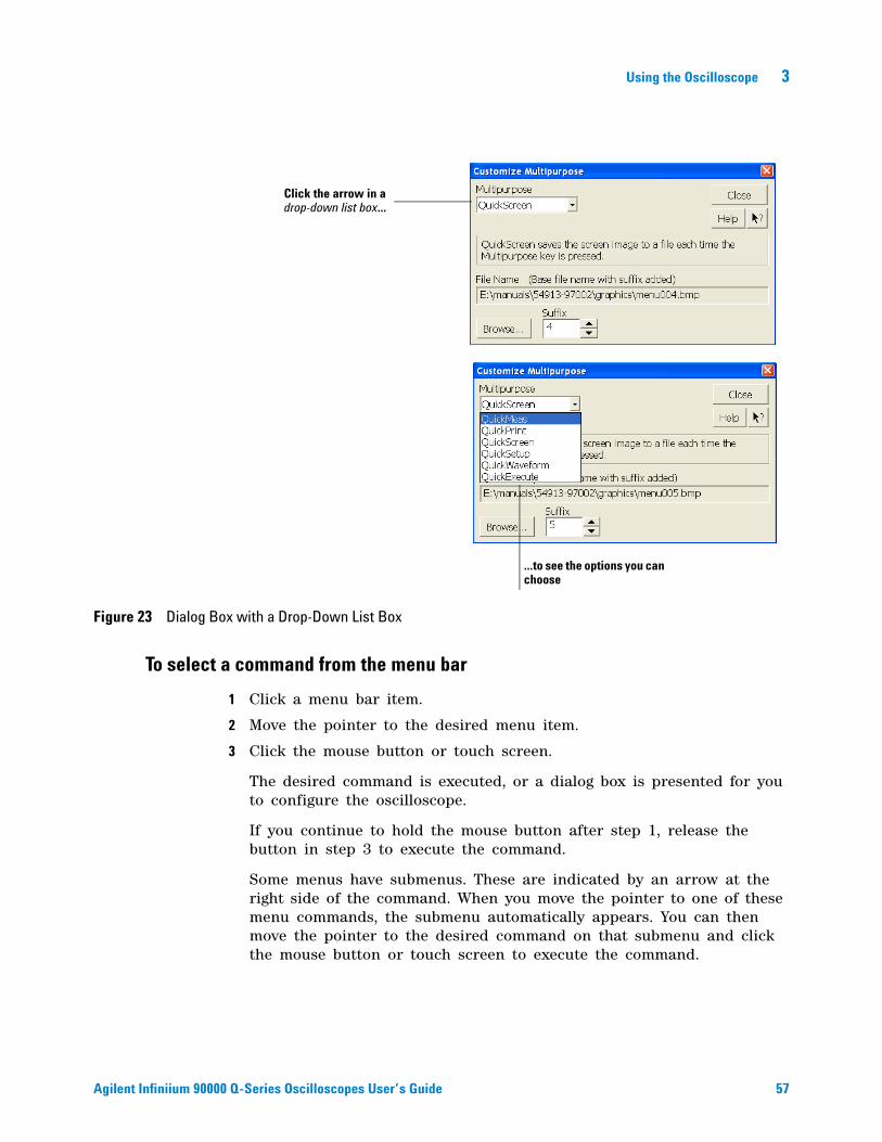
• To use a drop- down list box, click the arrow at the right side of the box. Then click the desired choice to highlight it.
See the Multipurpose selection list box in Figure 23.
• To use a spin box, click the up arrow to increase the value displayed in the box, and the down arrow to decrease it.
See the Suffix spin box in Figure 23.
• To move a dialog box, press and hold the left mouse button or touch screen stylus with the pointer in the title bar, drag the box to a new position on the screen, then release.
• To close a dialog box, click the “X” symbol in the upper right corner of the box, or click Close in the box.
Using the Oscilloscope 3
Agilent Infiniium 90000 Q-Series Oscilloscopes User’s Guide 55
Figure 21 Dialog Box Interface Elements
Click to put a check mark in the check box and enable Connect Dots mode
Click one of these check boxes to select Color Grade or Infinite persistence
Click and drag the title bar to move the dialog box on the screen
Click and drag the Intensity control slider up to increase the waveform brightness
Click and drag the Intensity control slider down to decrease the waveform brightness
56 Agilent Infiniium 90000 Q-Series Oscilloscopes User’s Guide
3 Using the Oscilloscope
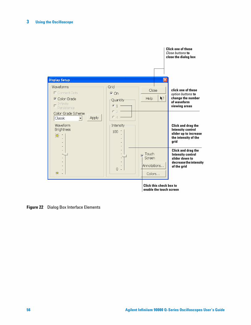
Figure 22 Dialog Box Interface Elements
Click and drag the Intensity control slider up to increase the intensity of the grid
Click and drag the Intensity control slider down to decrease the intensity of the grid
Click one of these Close buttons to close the dialog box
click one of these option buttons to change the number of waveform viewing areas
Click this check box to enable the touch screen
Using the Oscilloscope 3
Agilent Infiniium 90000 Q-Series Oscilloscopes User’s Guide 57
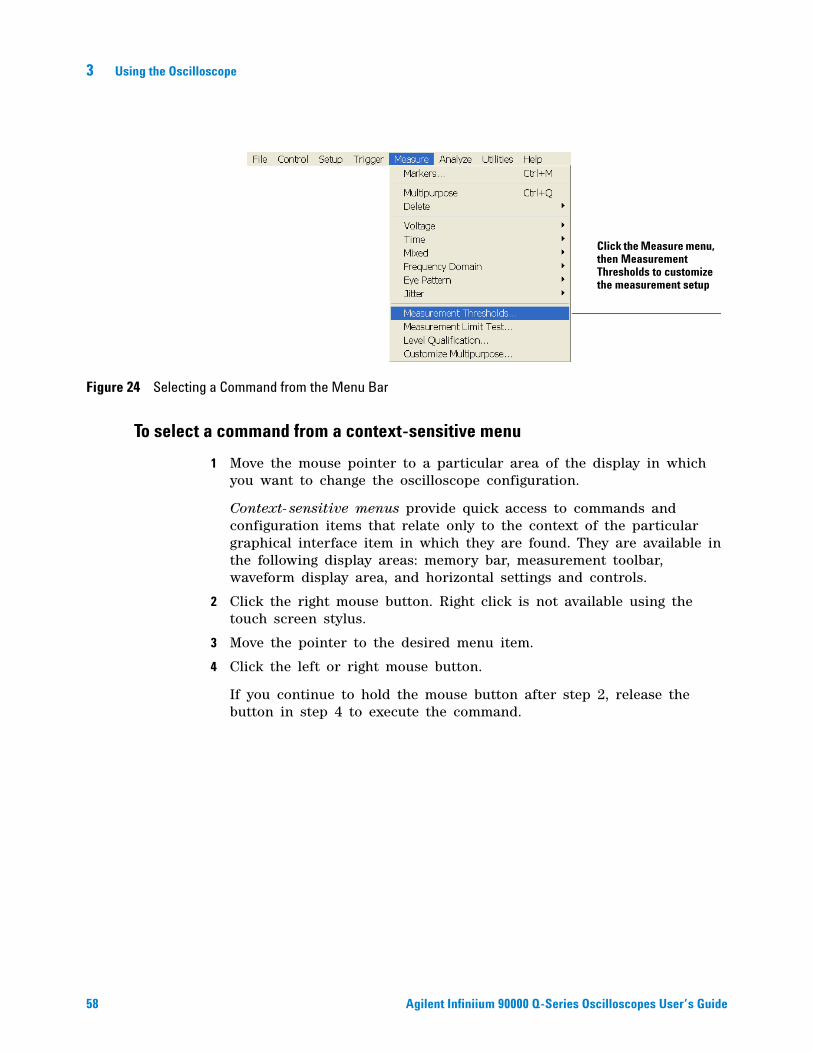
To select a command from the menu bar
1 Click a menu bar item.
2 Move the pointer to the desired menu item.
3 Click the mouse button or touch screen.
The desired command is executed, or a dialog box is presented for you to configure the oscilloscope.
If you continue to hold the mouse button after step 1, release the button in step 3 to execute the command.
Some menus have submenus. These are indicated by an arrow at the right side of the command. When you move the pointer to one of these menu commands, the submenu automatically appears. You can then move the pointer to the desired command on that submenu and click the mouse button or touch screen to execute the command.
Figure 23 Dialog Box with a Drop-Down List Box
...to see the options you can choose
Click the arrow in a drop-down list box...
58 Agilent Infiniium 90000 Q-Series Oscilloscopes User’s Guide
3 Using the Oscilloscope
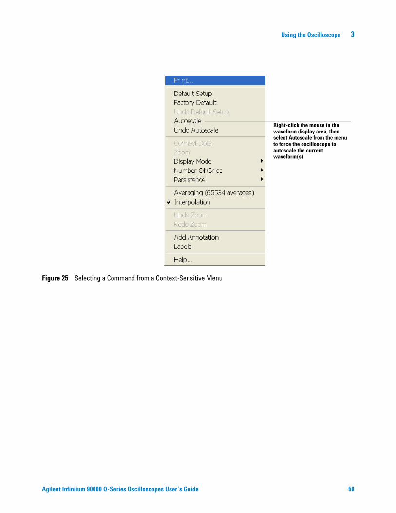
To select a command from a context-sensitive menu
1 Move the mouse pointer to a particular area of the display in which you want to change the oscilloscope configuration.
Context- sensitive menus provide quick access to commands and configuration items that relate only to the context of the particular graphical interface item in which they are found. They are available in the following display areas: memory bar, measurement toolbar, waveform display area, and horizontal settings and controls.
2 Click the right mouse button. Right click is not available using the touch screen stylus.
3 Move the pointer to the desired menu item.
4 Click the left or right mouse button.
If you continue to hold the mouse button after step 2, release the button in step 4 to execute the command.
Figure 24 Selecting a Command from the Menu Bar
Click the Measure menu, then Measurement Thresholds to customize the measurement setup
Using the Oscilloscope 3
Agilent Infiniium 90000 Q-Series Oscilloscopes User’s Guide 59
Figure 25 Selecting a Command from a Context-Sensitive Menu
Right-click the mouse in the waveform display area, then select Autoscale from the menu to force the oscilloscope to autoscale the current waveform(s)
60 Agilent Infiniium 90000 Q-Series Oscilloscopes User’s Guide
3 Using the Oscilloscope
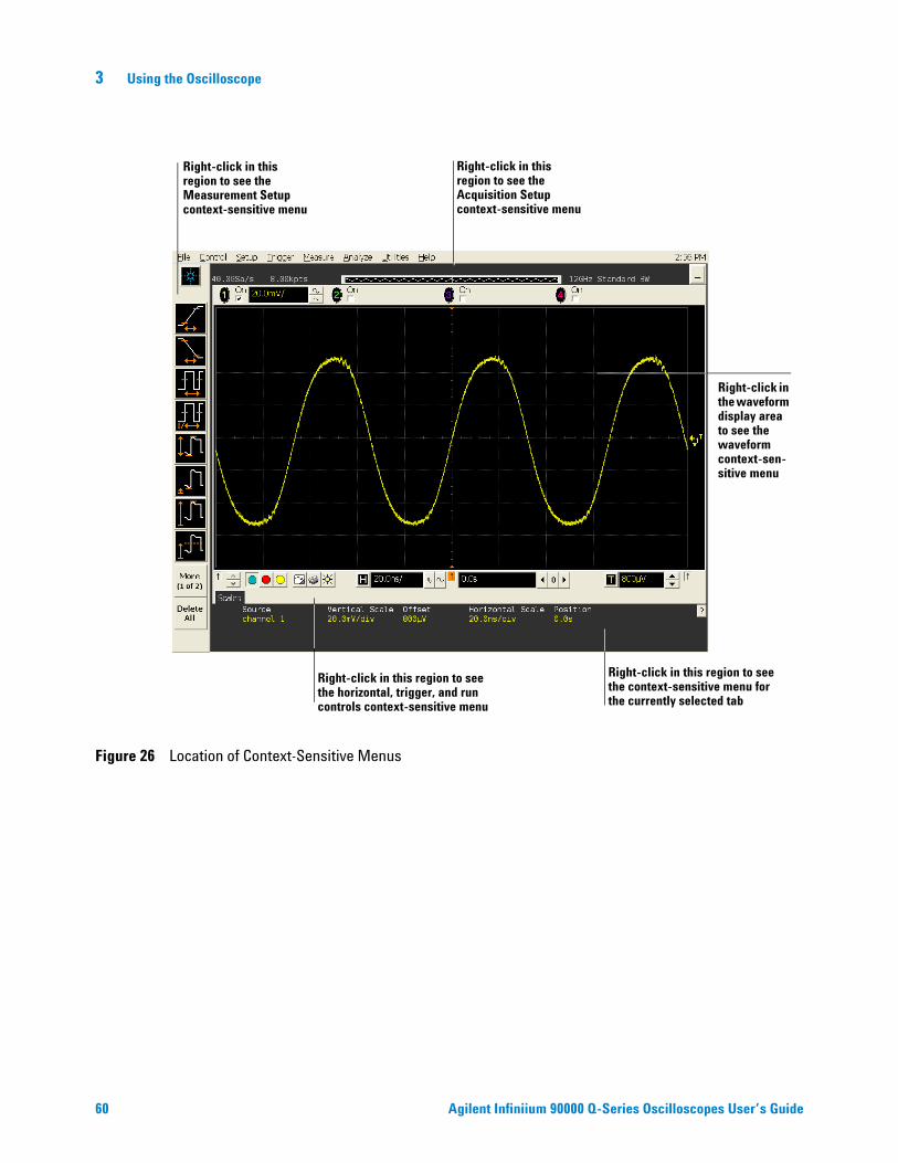
Figure 26 Location of Context-Sensitive Menus
Right-click in this region to see the Acquisition Setup context-sensitive menu
Right-click in this region to see the Measurement Setup context-sensitive menu
Right-click in this region to see the horizontal, trigger, and run controls context-sensitive menu
Right-click in the waveform display area to see the waveform context-sen-sitive menu
Right-click in this region to see the context-sensitive menu for the currently selected tab
Using the Oscilloscope 3
Agilent Infiniium 90000 Q-Series Oscilloscopes User’s Guide 61
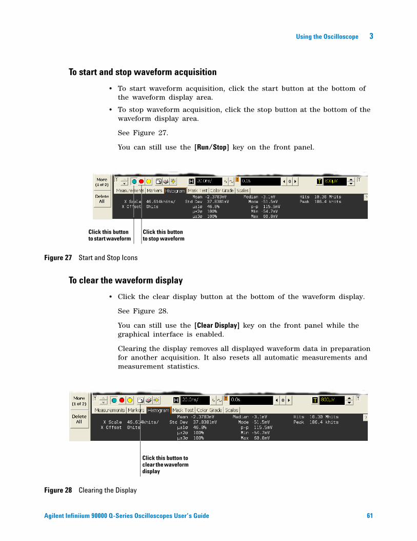
To start and stop waveform acquisition
• To start waveform acquisition, click the start button at the bottom of the waveform display area.
• To stop waveform acquisition, click the stop button at the bottom of the waveform display area.
See Figure 27.
You can still use the [Run/Stop] key on the front panel.
To clear the waveform display
• Click the clear display button at the bottom of the waveform display.
See Figure 28.
You can still use the [Clear Display] key on the front panel while the graphical interface is enabled.
Clearing the display removes all displayed waveform data in preparation for another acquisition. It also resets all automatic measurements and measurement statistics.
Figure 27 Start and Stop Icons
Click this button to stop waveform
Click this button to start waveform
Figure 28 Clearing the Display
Click this button to clear the waveform display
62 Agilent Infiniium 90000 Q-Series Oscilloscopes User’s Guide
3 Using the Oscilloscope
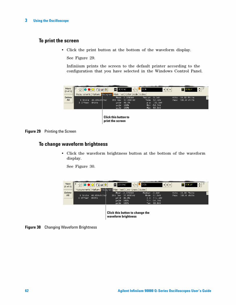
To print the screen
• Click the print button at the bottom of the waveform display.
See Figure 29.
Infiniium prints the screen to the default printer according to the configuration that you have selected in the Windows Control Panel.
To change waveform brightness
• Click the waveform brightness button at the bottom of the waveform display.
See Figure 30.
Figure 29 Printing the Screen
Click this button to print the screen
Figure 30 Changing Waveform Brightness
Click this button to change the waveform brightness
Using the Oscilloscope 3
Agilent Infiniium 90000 Q-Series Oscilloscopes User’s Guide 63
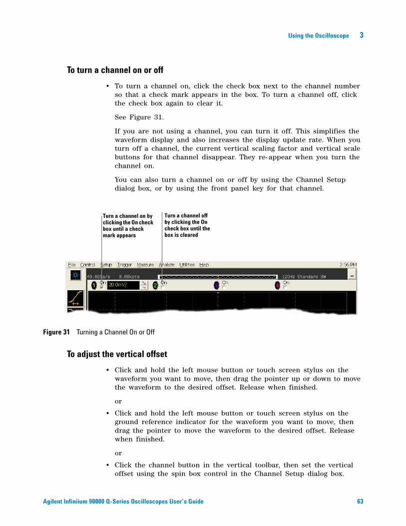
To turn a channel on or off
• To turn a channel on, click the check box next to the channel number so that a check mark appears in the box. To turn a channel off, click the check box again to clear it.
See Figure 31.
If you are not using a channel, you can turn it off. This simplifies the waveform display and also increases the display update rate. When you turn off a channel, the current vertical scaling factor and vertical scale buttons for that channel disappear. They re- appear when you turn the channel on.
You can also turn a channel on or off by using the Channel Setup dialog box, or by using the front panel key for that channel.
To adjust the vertical offset
• Click and hold the left mouse button or touch screen stylus on the waveform you want to move, then drag the pointer up or down to move the waveform to the desired offset. Release when finished.
or
• Click and hold the left mouse button or touch screen stylus on the ground reference indicator for the waveform you want to move, then drag the pointer to move the waveform to the desired offset. Release when finished.
or
• Click the channel button in the vertical toolbar, then set the vertical offset using the spin box control in the Channel Setup dialog box.
Figure 31 Turning a Channel On or Off
Turn a channel off by clicking the On check box until the box is cleared
Turn a channel on by clicking the On check box until a check mark appears
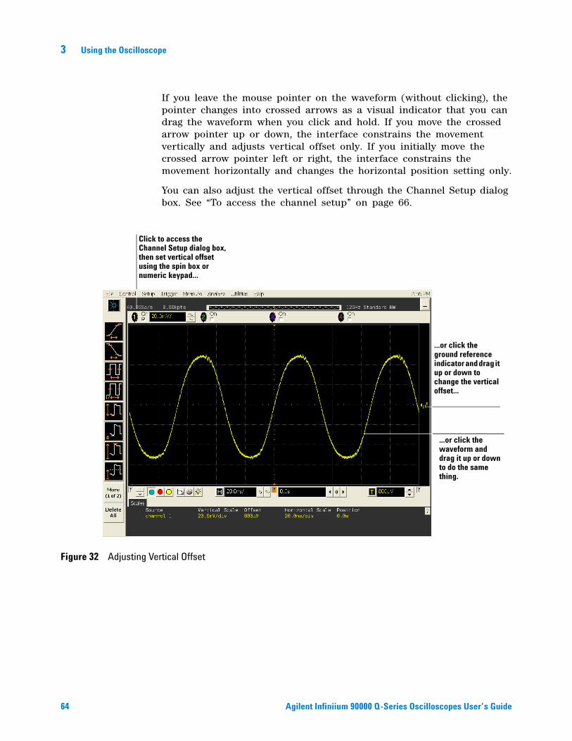
64 Agilent Infiniium 90000 Q-Series Oscilloscopes User’s Guide
3 Using the Oscilloscope
If you leave the mouse pointer on the waveform (without clicking), the pointer changes into crossed arrows as a visual indicator that you can drag the waveform when you click and hold. If you move the crossed arrow pointer up or down, the interface constrains the movement vertically and adjusts vertical offset only. If you initially move the crossed arrow pointer left or right, the interface constrains the movement horizontally and changes the horizontal position setting only.
You can also adjust the vertical offset through the Channel Setup dialog box. See “To access the channel setup” on page 66.
Figure 32 Adjusting Vertical Offset
...or click the waveform and drag it up or down to do the same thing.
...or click the ground reference indicator and drag it up or down to change the vertical offset...
Click to access the Channel Setup dialog box, then set vertical offset using the spin box or numeric keypad...
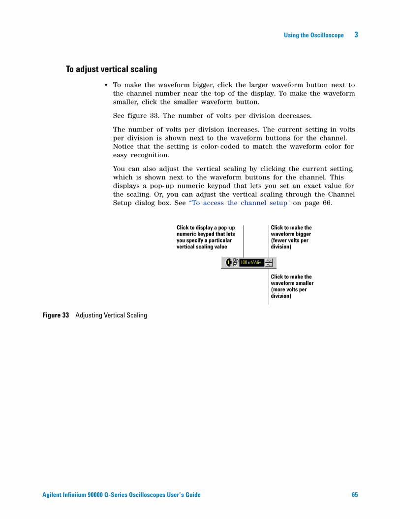
Using the Oscilloscope 3
Agilent Infiniium 90000 Q-Series Oscilloscopes User’s Guide 65
To adjust vertical scaling
• To make the waveform bigger, click the larger waveform button next to the channel number near the top of the display. To make the waveform smaller, click the smaller waveform button.
See figure 33. The number of volts per division decreases.
The number of volts per division increases. The current setting in volts per division is shown next to the waveform buttons for the channel. Notice that the setting is color- coded to match the waveform color for easy recognition.
You can also adjust the vertical scaling by clicking the current setting, which is shown next to the waveform buttons for the channel. This displays a pop- up numeric keypad that lets you set an exact value for the scaling. Or, you can adjust the vertical scaling through the Channel Setup dialog box. See “To access the channel setup" on page 66.
Figure 33 Adjusting Vertical Scaling
Click to make the waveform bigger (fewer volts per division)
Click to make the waveform smaller (more volts per division)
Click to display a pop-up numeric keypad that lets you specify a particular vertical scaling value
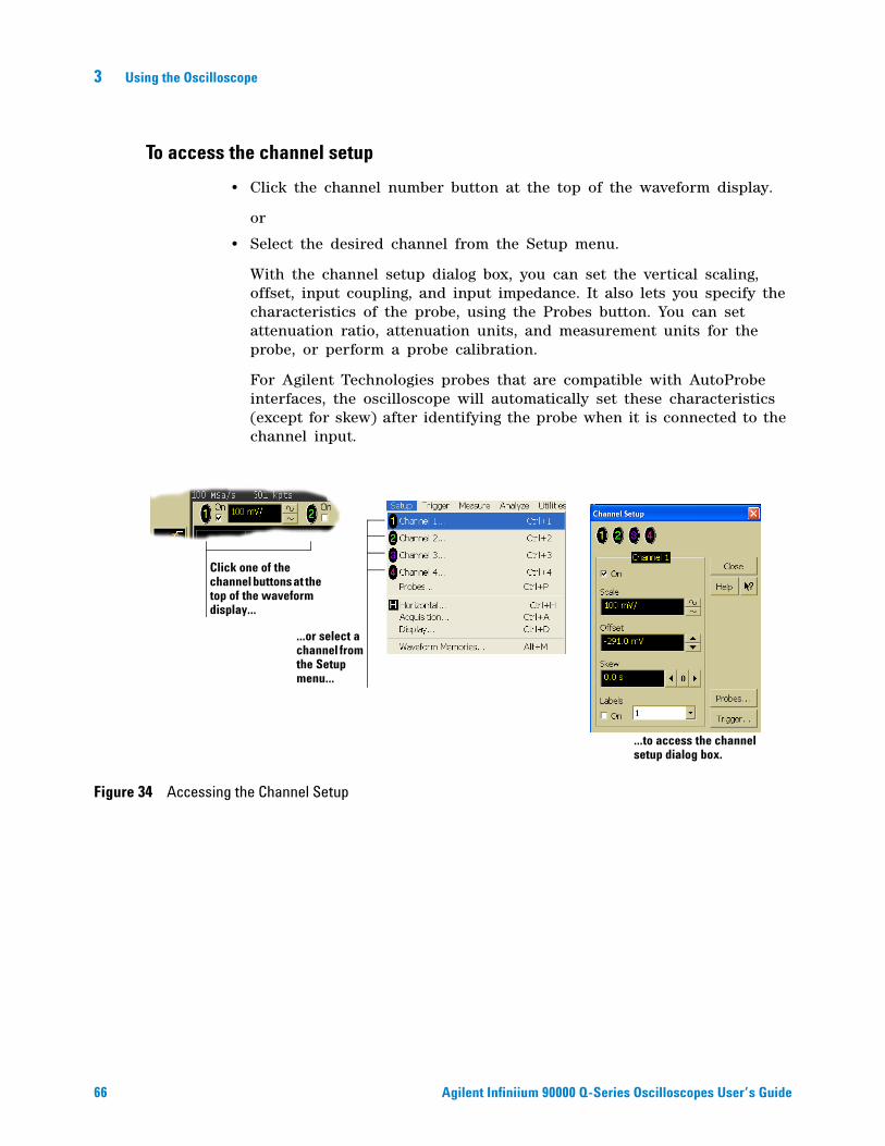
66 Agilent Infiniium 90000 Q-Series Oscilloscopes User’s Guide
3 Using the Oscilloscope
To access the channel setup
• Click the channel number button at the top of the waveform display.
or
• Select the desired channel from the Setup menu.
With the channel setup dialog box, you can set the vertical scaling, offset, input coupling, and input impedance. It also lets you specify the characteristics of the probe, using the Probes button. You can set attenuation ratio, attenuation units, and measurement units for the probe, or perform a probe calibration.
For Agilent Technologies probes that are compatible with AutoProbe interfaces, the oscilloscope will automatically set these characteristics (except for skew) after identifying the probe when it is connected to the channel input.
Figure 34 Accessing the Channel Setup
Click one of the channel buttons at the top of the waveform display...
...or select a channel from the Setup menu...
...to access the channel setup dialog box.
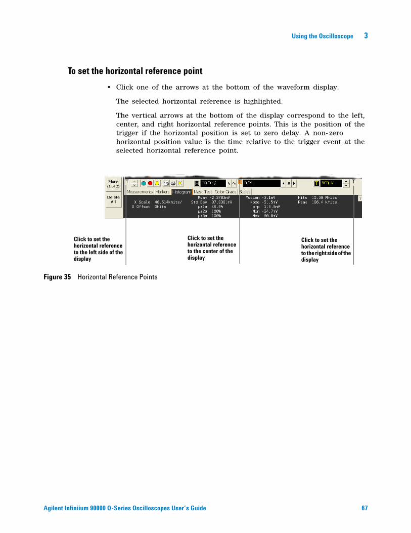
Using the Oscilloscope 3
Agilent Infiniium 90000 Q-Series Oscilloscopes User’s Guide 67
To set the horizontal reference point
• Click one of the arrows at the bottom of the waveform display.
The selected horizontal reference is highlighted.
The vertical arrows at the bottom of the display correspond to the left, center, and right horizontal reference points. This is the position of the trigger if the horizontal position is set to zero delay. A non- zero horizontal position value is the time relative to the trigger event at the selected horizontal reference point.
Figure 35 Horizontal Reference Points
Click to set the horizontal reference to the left side of the display
Click to set the horizontal reference to the center of the display
Click to set the horizontal reference to the right side of the display
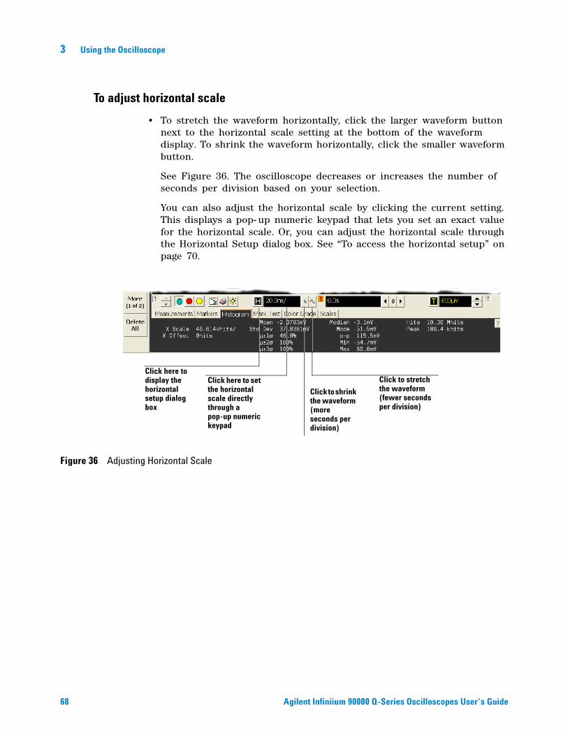
68 Agilent Infiniium 90000 Q-Series Oscilloscopes User’s Guide
3 Using the Oscilloscope
To adjust horizontal scale
• To stretch the waveform horizontally, click the larger waveform button next to the horizontal scale setting at the bottom of the waveform display. To shrink the waveform horizontally, click the smaller waveform button.
See Figure 36. The oscilloscope decreases or increases the number of seconds per division based on your selection.
You can also adjust the horizontal scale by clicking the current setting. This displays a pop- up numeric keypad that lets you set an exact value for the horizontal scale. Or, you can adjust the horizontal scale through the Horizontal Setup dialog box. See “To access the horizontal setup” on page 70.
Figure 36 Adjusting Horizontal Scale
Click to stretch the waveform (fewer seconds per division)
Click to shrink the waveform (more seconds per division)
Click here to set the horizontal scale directly through a pop-up numeric keypad
Click here to display the horizontal setup dialog box
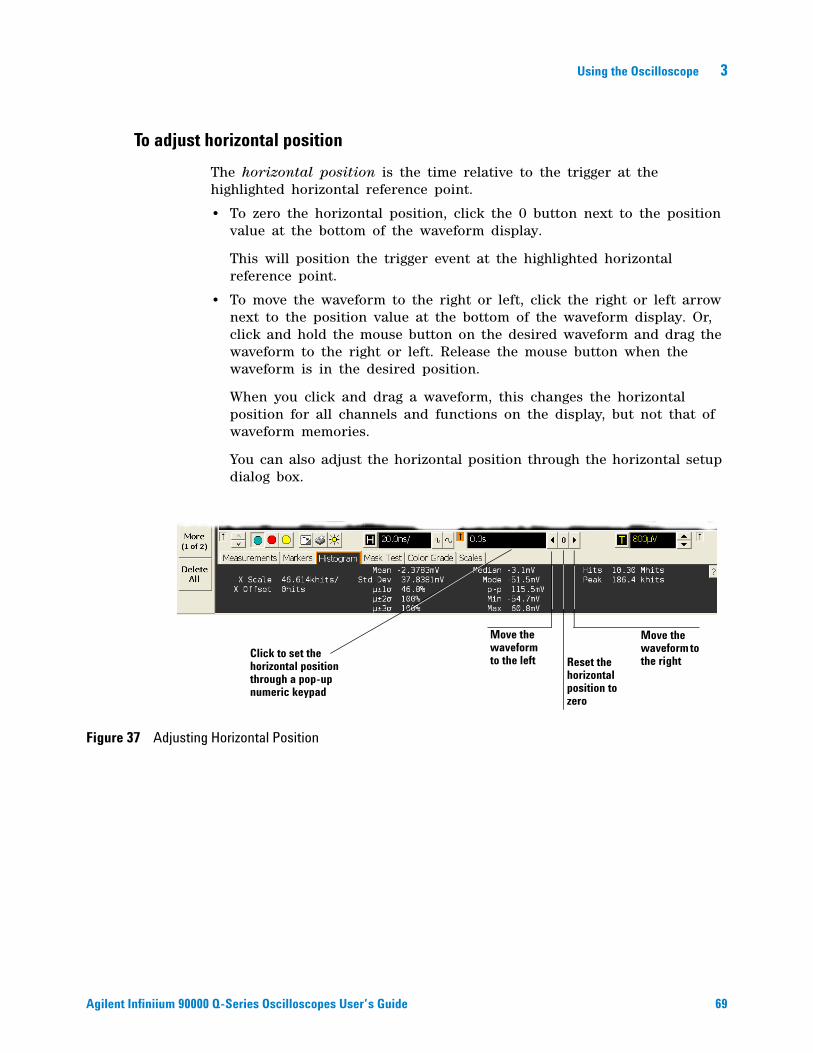
Using the Oscilloscope 3
Agilent Infiniium 90000 Q-Series Oscilloscopes User’s Guide 69
To adjust horizontal position
The horizontal position is the time relative to the trigger at the highlighted horizontal reference point.
• To zero the horizontal position, click the 0 button next to the position value at the bottom of the waveform display.
This will position the trigger event at the highlighted horizontal reference point.
• To move the waveform to the right or left, click the right or left arrow next to the position value at the bottom of the waveform display. Or, click and hold the mouse button on the desired waveform and drag the waveform to the right or left. Release the mouse button when the waveform is in the desired position.
When you click and drag a waveform, this changes the horizontal position for all channels and functions on the display, but not that of waveform memories.
You can also adjust the horizontal position through the horizontal setup dialog box.
Figure 37 Adjusting Horizontal Position
Reset the horizontal position to zero
Move the waveform to the right
Move the waveform to the left
Click to set the horizontal position through a pop-up numeric keypad
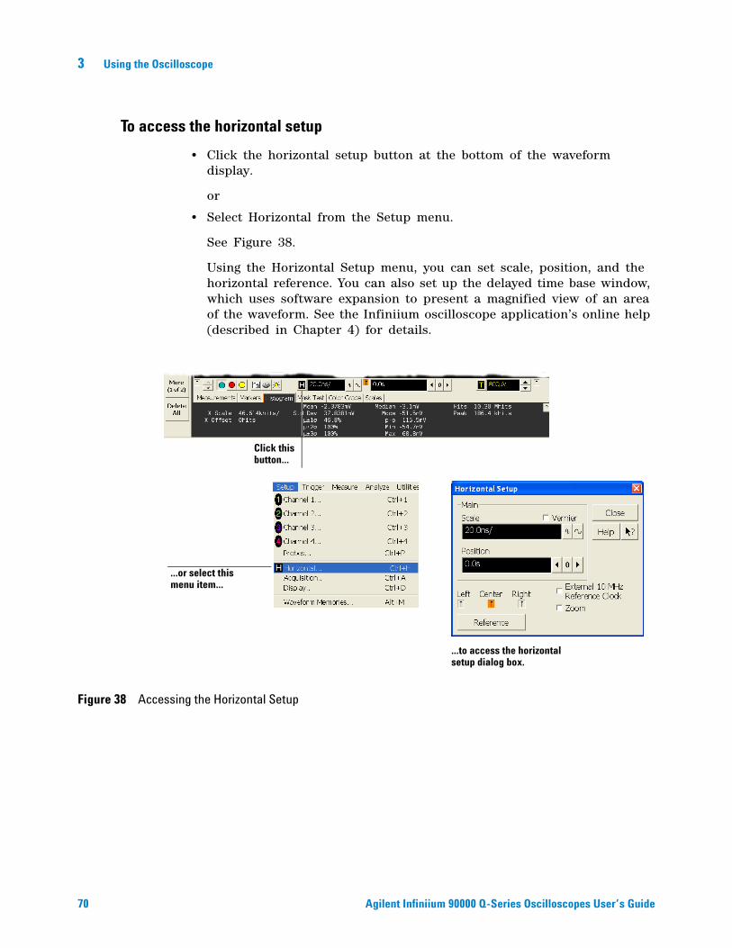
70 Agilent Infiniium 90000 Q-Series Oscilloscopes User’s Guide
3 Using the Oscilloscope
To access the horizontal setup
• Click the horizontal setup button at the bottom of the waveform display.
or
• Select Horizontal from the Setup menu.
See Figure 38.
Using the Horizontal Setup menu, you can set scale, position, and the horizontal reference. You can also set up the delayed time base window, which uses software expansion to present a magnified view of an area of the waveform. See the Infiniium oscilloscope application’s online help (described in Chapter 4) for details.
Figure 38 Accessing the Horizontal Setup
...or select this menu item...
...to access the horizontal setup dialog box.
Click this button...
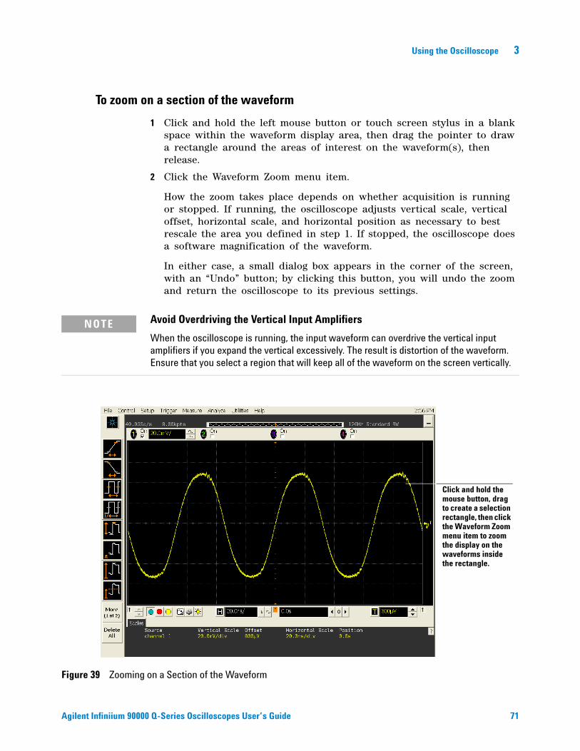
Using the Oscilloscope 3
Agilent Infiniium 90000 Q-Series Oscilloscopes User’s Guide 71
To zoom on a section of the waveform
1 Click and hold the left mouse button or touch screen stylus in a blank space within the waveform display area, then drag the pointer to draw a rectangle around the areas of interest on the waveform(s), then release.
2 Click the Waveform Zoom menu item.
How the zoom takes place depends on whether acquisition is running or stopped. If running, the oscilloscope adjusts vertical scale, vertical offset, horizontal scale, and horizontal position as necessary to best rescale the area you defined in step 1. If stopped, the oscilloscope does a software magnification of the waveform.
In either case, a small dialog box appears in the corner of the screen, with an “Undo” button; by clicking this button, you will undo the zoom and return the oscilloscope to its previous settings.
NOTE Avoid Overdriving the Vertical Input Amplifiers
When the oscilloscope is running, the input waveform can overdrive the vertical input amplifiers if you expand the vertical excessively. The result is distortion of the waveform. Ensure that you select a region that will keep all of the waveform on the screen vertically.
Figure 39 Zooming on a Section of the Waveform
Click and hold the mouse button, drag to create a selection rectangle, then click the Waveform Zoom menu item to zoom the display on the waveforms inside the rectangle.
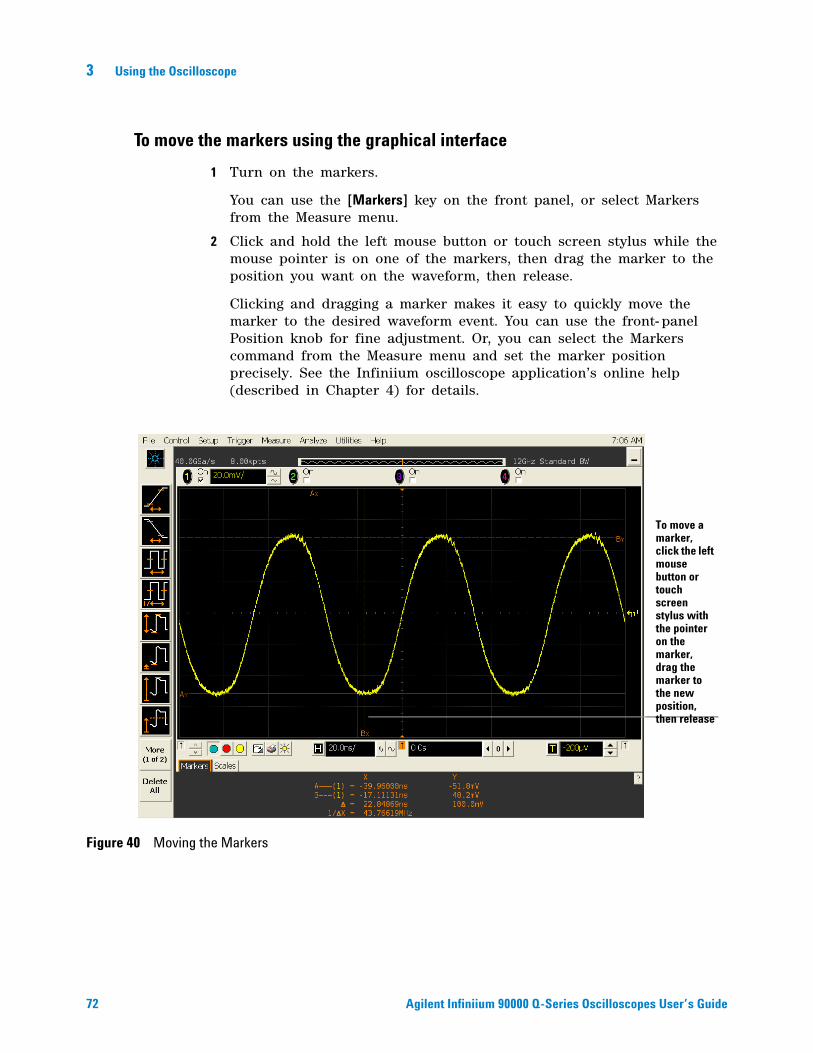
72 Agilent Infiniium 90000 Q-Series Oscilloscopes User’s Guide
3 Using the Oscilloscope
To move the markers using the graphical interface
1 Turn on the markers.
You can use the [Markers] key on the front panel, or select Markers from the Measure menu.
2 Click and hold the left mouse button or touch screen stylus while the mouse pointer is on one of the markers, then drag the marker to the position you want on the waveform, then release.
Clicking and dragging a marker makes it easy to quickly move the marker to the desired waveform event. You can use the front- panel Position knob for fine adjustment. Or, you can select the Markers command from the Measure menu and set the marker position precisely. See the Infiniium oscilloscope application’s online help (described in Chapter 4) for details.
Figure 40 Moving the Markers
To move a marker, click the left mouse button or touch screen stylus with the pointer on the marker, drag the marker to the new position, then release
Using the Oscilloscope 3
Agilent Infiniium 90000 Q-Series Oscilloscopes User’s Guide 73
To make a measurement on a waveform
• Click and hold the mouse button or touch screen stylus on a measurement icon, then drag the icon to the waveform event you want to measure then release.
or
• Click a measurement icon, then specify which source you want to measure in the dialog box that is displayed.
For measurements on waveform features, such as those that involve waveform edges, if you click the measurement icon and specify a source, the measurement defaults to using the feature closest to the horizontal reference point. When you make the measurement using drag- and- drop, the measurement uses the waveform feature closest to the point where you drop the icon.
Only the most commonly used measurements are available on the toolbar. Others are available by selecting them from the Measure menu. A few specialized measurements are available only through the remote programming command set. See the Programmer’s Reference.
When you drag and drop a measurement icon on a waveform, notice that the icon outline changes color to match the color of each waveform it touches. This lets you easily see which waveform will be measured when you release. Also, the measurement results are also displayed in color to make it easy to see which waveform source is being measured.
For edge- sensitive measurements, when you drop the measurement icon on a waveform, a geometric icon appears in the waveform marker color. This icon shows exactly where the measurement is being made. The icon is also displayed next to the measurement results readout to associate the readout with the waveform and feature being measured. See Figure 41. This feature helps you distinguish measurement results from each other when you make multiple measurements on the same waveform, but at different waveform features. For example, a series of rise time measurements on several different edges of the same waveform all have unique geometric icons to show each measurement’s location.
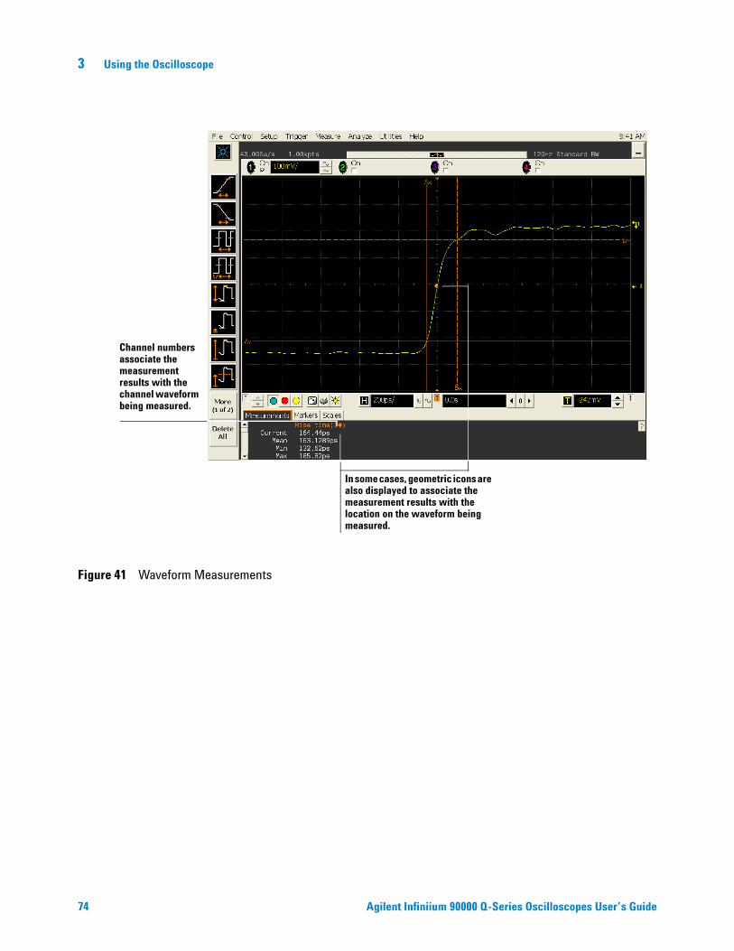
74 Agilent Infiniium 90000 Q-Series Oscilloscopes User’s Guide
3 Using the Oscilloscope
Figure 41 Waveform Measurements
In some cases, geometric icons are also displayed to associate the measurement results with the location on the waveform being measured.
Channel numbers associate the measurement results with the channel waveform being measured.
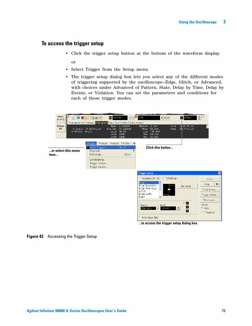
Using the Oscilloscope 3
Agilent Infiniium 90000 Q-Series Oscilloscopes User’s Guide 75
To access the trigger setup
• Click the trigger setup button at the bottom of the waveform display.
or
• Select Trigger from the Setup menu.
• The trigger setup dialog box lets you select any of the different modes of triggering supported by the oscilloscope—Edge, Glitch, or Advanced, with choices under Advanced of Pattern, State, Delay by Time, Delay by Events, or Violation. You can set the parameters and conditions for each of those trigger modes.
Figure 42 Accessing the Trigger Setup
Click this button...
...to access the trigger setup dialog box.
...or select this menu item...
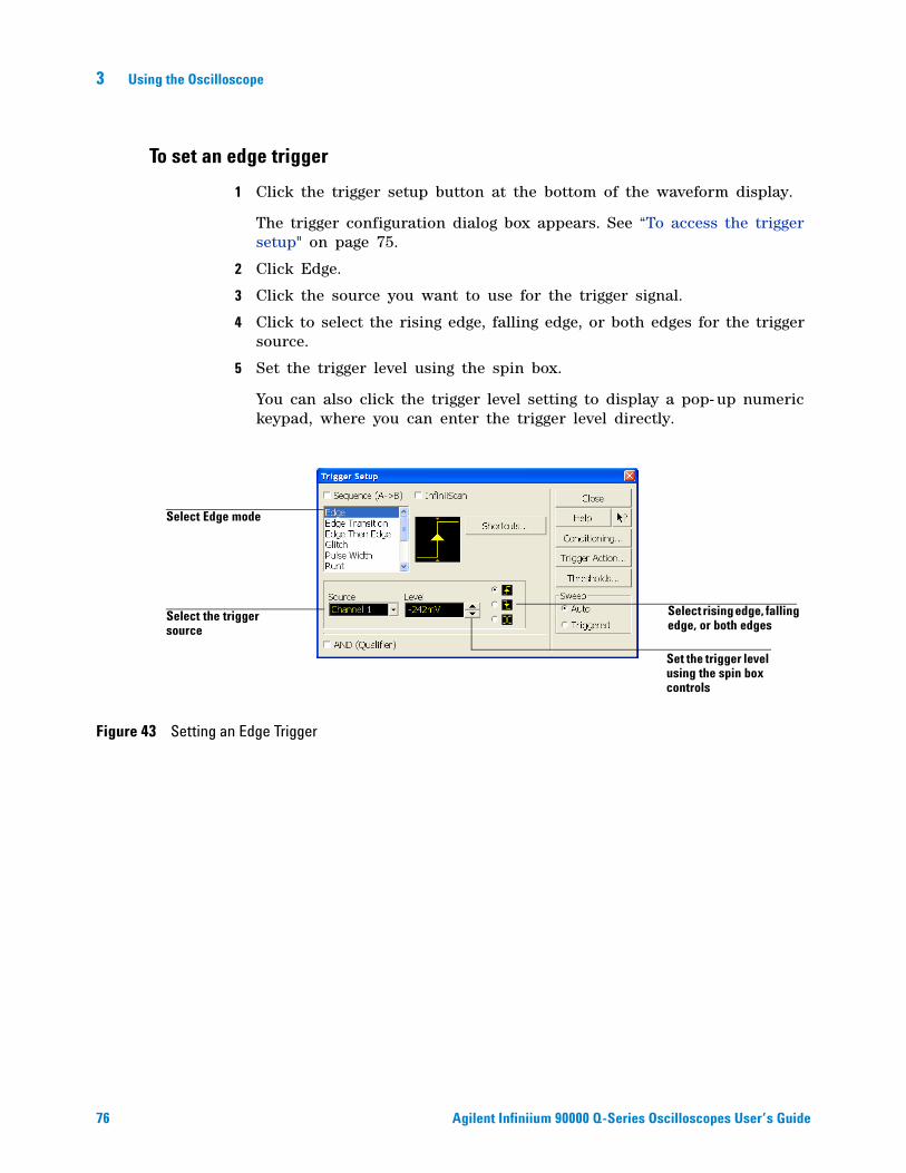
76 Agilent Infiniium 90000 Q-Series Oscilloscopes User’s Guide
3 Using the Oscilloscope
To set an edge trigger
1 Click the trigger setup button at the bottom of the waveform display.
The trigger configuration dialog box appears. See “To access the trigger setup" on page 75.
2 Click Edge.
3 Click the source you want to use for the trigger signal.
4 Click to select the rising edge, falling edge, or both edges for the trigger source.
5 Set the trigger level using the spin box.
You can also click the trigger level setting to display a pop- up numeric keypad, where you can enter the trigger level directly.
Figure 43 Setting an Edge Trigger
Select rising edge, falling edge, or both edges
Set the trigger level using the spin box controls
Select the trigger source
Select Edge mode
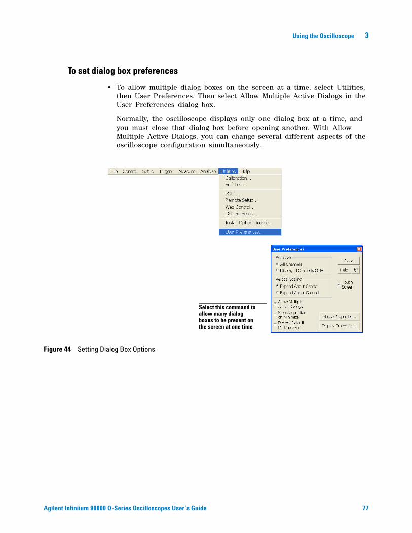
Using the Oscilloscope 3
Agilent Infiniium 90000 Q-Series Oscilloscopes User’s Guide 77
To set dialog box preferences
• To allow multiple dialog boxes on the screen at a time, select Utilities, then User Preferences. Then select Allow Multiple Active Dialogs in the User Preferences dialog box.
Normally, the oscilloscope displays only one dialog box at a time, and you must close that dialog box before opening another. With Allow Multiple Active Dialogs, you can change several different aspects of the oscilloscope configuration simultaneously.
Figure 44 Setting Dialog Box Options
Select this command to allow many dialog boxes to be present on the screen at one time
78 Agilent Infiniium 90000 Q-Series Oscilloscopes User’s Guide
3 Using the Oscilloscope
Removable Hard Drive
The Infiniium 90000 Q- Series oscilloscopes have a removable hard drive.
To recover your Infiniium hard disk
The Infiniium hard disk recovery system is contained in a hidden partition on the Infiniium hard disk. If you have to use the recovery system, the Infiniium hard disk is returned to the condition it was in when it left the factory. Before recovering the Infiniium hard disk, use the following procedure to return the Infiniium to normal operation.
1 Turn off the Infiniium.
2 Turn on the Infiniium. If the oscilloscope does not successfully restart then try recycling the power again.
3 After the Windows 7 load screen disappears, press and release the Infiniium [Default Setup] key on the front panel. If the oscilloscope still does not successfully restart, follow the instructions for recovering the hard drive.
Infiniium Hard Drive Recovery
Use the following instructions to recover your Infiniium hard drive.
1 Turn off the Infiniium.
2 Connect the keyboard to the keyboard connector on the rear panel of the oscilloscope.
3 Connect the mouse to the mouse connector on the rear panel of the oscilloscope.
4 Turn on the Infiniium.
5 When you see the message press F2 to boot the Infiniium Recovery System, press F2 and follow the on- screen instructions.
6 Once the recovery process is finished and the oscilloscope is running, check in the About Infiniium dialog box under installed options to see if all of the options you ordered are installed. If the options are not installed, please install them using the license keys provided on the oscilloscope option license certificates you received, or refer to the rear panel of the oscilloscope.
CAUTION Power down the instrument before removal or insertion of a removable hard drive.
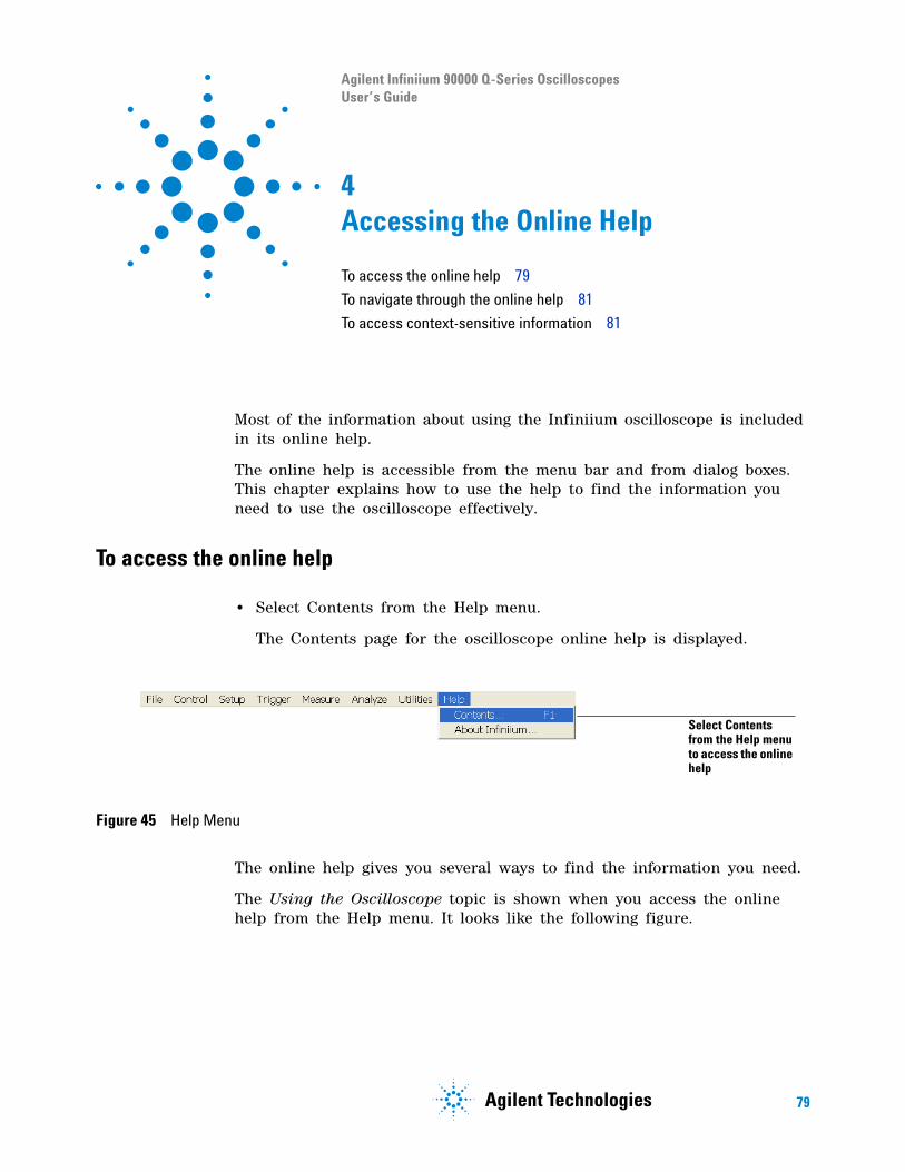
s1 79
Agilent Infiniium 90000 Q-Series Oscilloscopes User’s Guide
4Accessing the Online Help
To access the online help 79
To navigate through the online help 81
To access context-sensitive information 81
Most of the information about using the Infiniium oscilloscope is included in its online help.
The online help is accessible from the menu bar and from dialog boxes. This chapter explains how to use the help to find the information you need to use the oscilloscope effectively.
To access the online help
• Select Contents from the Help menu.
The Contents page for the oscilloscope online help is displayed.
The online help gives you several ways to find the information you need.
The Using the Oscilloscope topic is shown when you access the online help from the Help menu. It looks like the following figure.
Figure 45 Help Menu
Select Contents from the Help menu to access the online help
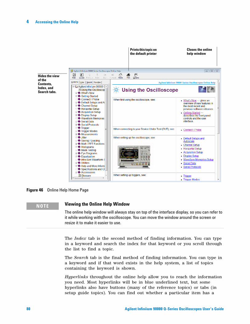
80 Agilent Infiniium 90000 Q-Series Oscilloscopes User’s Guide
4 Accessing the Online Help
The Index tab is the second method of finding information. You can type in a keyword and search the index for that keyword or you scroll through the list to find a topic.
The Search tab is the final method of finding information. You can type in a keyword and if that word exists in the help system, a list of topics containing the keyword is shown.
Hyperlinks throughout the online help allow you to reach the information you need. Most hyperlinks will be in blue underlined text, but some hyperlinks also have buttons (many of the reference topics) or tabs (in setup guide topics). You can find out whether a particular item has a
Figure 46 Online Help Home Page
NOTE Viewing the Online Help Window
The online help window will always stay on top of the interface display, so you can refer to it while working with the oscilloscope. You can move the window around the screen or resize it to make it easier to use.
Closes the online help window
Prints this topic on the default printer
Hides the view of the Contents, Index, and Search tabs.
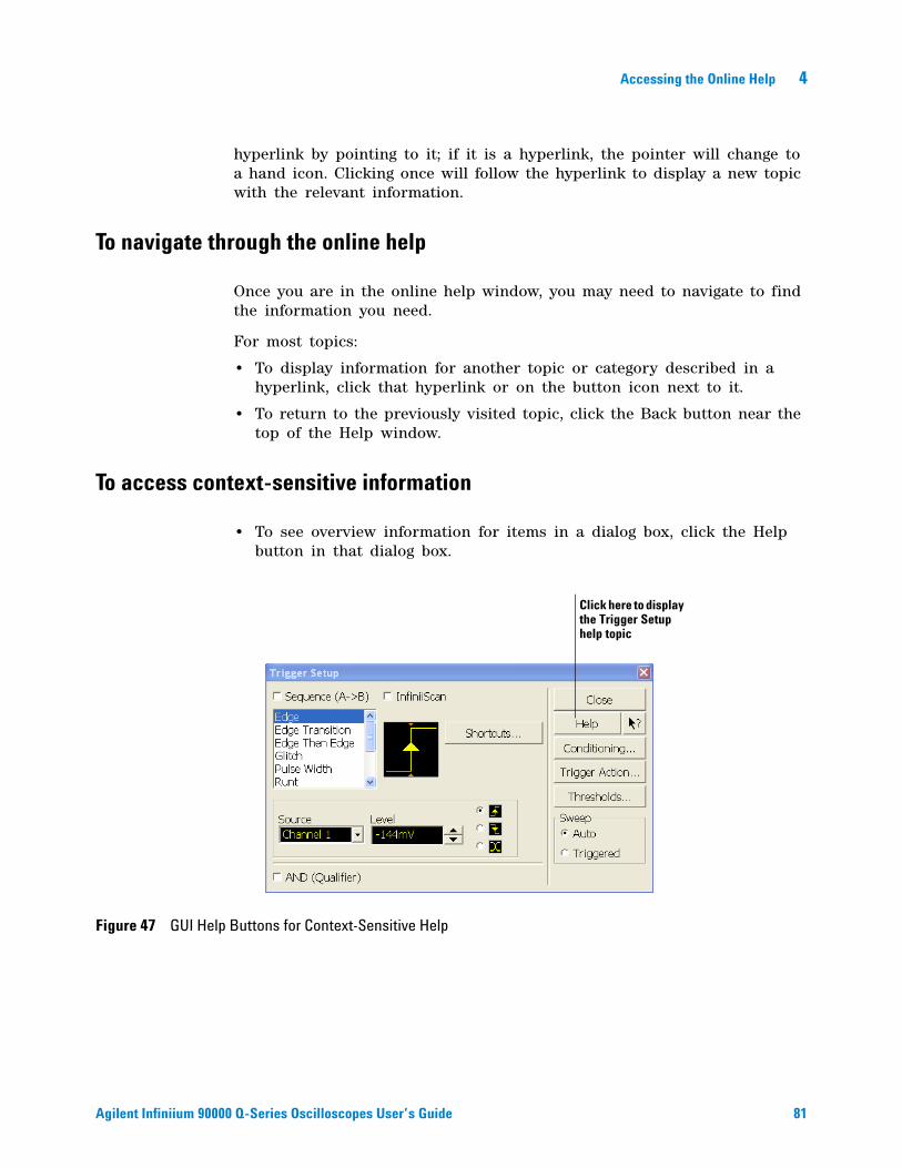
Accessing the Online Help 4
Agilent Infiniium 90000 Q-Series Oscilloscopes User’s Guide 81
hyperlink by pointing to it; if it is a hyperlink, the pointer will change to a hand icon. Clicking once will follow the hyperlink to display a new topic with the relevant information.
To navigate through the online help
Once you are in the online help window, you may need to navigate to find the information you need.
For most topics:
• To display information for another topic or category described in a hyperlink, click that hyperlink or on the button icon next to it.
• To return to the previously visited topic, click the Back button near the top of the Help window.
To access context-sensitive information
• To see overview information for items in a dialog box, click the Help button in that dialog box.
Figure 47 GUI Help Buttons for Context-Sensitive Help
Click here to display the Trigger Setup help topic

82 Agilent Infiniium 90000 Q-Series Oscilloscopes User’s Guide
4 Accessing the Online Help
s1 83
Agilent Infiniium 90000 Q-Series Oscilloscopes User’s Guide
ASafety Notices
Warnings 83
Safety Symbols 84
This apparatus has been designed and tested in accordance with UL 61010- 1:2004 2nd Edition, and has been supplied in a safe condition. This is a Safety Class I instrument (provided with terminal for protective earthing). Before applying power, verify that the correct safety precautions are taken (see the following warnings). In addition, note the external markings on the instrument that are described under "Safety Symbols."
Warnings
• The mains plug shall be inserted only in a socket outlet provided with a protective earth contact. You must not negate the protective action by using an extension cord (power cable) without a protective conductor (grounding). Grounding one conductor of a two- conductor outlet is not sufficient protection.
• Whenever it is likely that the ground protection is impaired, you must make the instrument inoperative and secure it against any unintended operation.
• Capacitors inside the instrument may retain a charge even if the instrument is disconnected from its source of supply.
• Do not operate the instrument in the presence of flammable gasses or fumes. Operation of any electrical instrument in such an environment constitutes a definite safety hazard.
• Do not use the instrument in a manner not specified by the manufacturer, or the protection provided by the equipment may be impaired.
84 Agilent Infiniium 90000 Q-Series Oscilloscopes User’s Guide
A Safety Notices
Safety Symbols
Instruction manual symbol: the product is marked with this symbol when it is necessary for you to refer to the instruction manual in order to protect against damage to the product.
Hazardous voltage symbol.
Frame or chassis terminal symbol: Used to indicate a circuit common connected to grounded chassis.
Agilent Infiniium 90000 Q-Series Oscilloscopes User’s Guide 85
Index
A
access methods, 79accessing
index, 80online help, 79trigger setup, 75
accessoriesand options, 15
accurate measurements using markers, 46acquisition
clearing display before, 61running and stopping, 38starting and stopping, 38, 52, 61
acquisition run controls, 38active dialog boxes
allowing multiple, 77adjusting
analog channel’s vertical offset, 43analog channel’s vertical scaling, 43horizontal position, 51, 69sweep speed, 68vertical offset, 51, 63, 64vertical scaling, 52, 65
advanced trigger, 43configuration, 53mode, 75
airflow requirements, 16Application software, 24arrangement of graphical interface, 49associating measurement results with
waveforms, 73Autoprobe interfaces, 66Autoscale, 23
B
behavior of online help windows, 80built-in help, 79buttons, 37
as hyperlink, 80channel setup, 66help, 81horizontal setup, 70question mark, 81trigger setup, 75, 76
C
calibrationoutput, 23
cautionscleaning, 26
center horizontal reference, 53, 67Channel keys, 42channel setup
accessing, 66button, 66
channelsdisplayed, 52turning on or off, 52, 63turning on or off analog channels, 42
check box, 54, 55, 56checking the oscilloscope, 14choosing
commands, 57, 58list items, 54
cleaning the oscilloscope, 26Clear Display key, 39clearing measurements, 50clearing the display, 39, 52, 61click, 54closing
dialog boxes, 54, 55, 56color
use of, 37, 49use of in interface, 73
commandsselecting, 57, 58
conditionstrigger, 75
configurationchannel, 66default, 23, 39dialog boxes, 77edge trigger, 44horizontal, 53, 70through menus, 52trigger, 43, 53, 75, 76
configuringquick measurements, 46
connectingLAN card, 17pointing device, 17power, 18probes, 19
constraints on waveform movement, 63contents
online help, 79contents topic, 79context-sensitive
information, 81menus, 52, 58, 60
controlsacquisition run, 38horizontal, 40measure, 45
trigger, 43vertical, 42
couplingtrigger input, 44
customizing display layout, 73cycling
markers through channels, 46measurements through channels, 46
D
default setup, 23Default Setup key, 39delayed sweep, 70dialog boxes, 54, 55, 56
information on, 81preferences for, 77
direct manipulation of waveforms, 63, 69Disk
Hard Disk Recovery, 78display
clearing, 39, 52, 61display area
waveforms, 51display layout
customizing, 73display of channels, 52display update rate
increasing, 42, 63drag-and-drop measurements, 49, 73drag-and-drop waveforms, 51, 63, 69drop-down list box, 54, 57
E
edge trigger, 43mode, 75, 76setting, 44
erasing the display, 39, 61
F
finding information, 79, 81front panel, 45
connections, 19interface, 31, 37
G
geometric measurement indicators, 50glitch trigger
mode, 75
86 Agilent Infiniium 90000 Q-Series Oscilloscopes User’s Guide
Index
graphical interface, 31arrangement of, 49
graticule, 45grid, 51ground reference indicator, 51, 63
H
Hard DiskRecovery, 78
helpbutton, 81
horizontaladjusting position, 40controls, 40zoomed timebase, 41
horizontal and trigger toolbar, 52horizontal position, 40, 70
adjusting, 40, 51, 53, 69in zoom mode, 41with respect to horizontal reference, 67
horizontal reference, 70indicators, 53setting, 67
horizontal setup, 53accessing, 70button, 70
horizontal sweep speed, 53adjusting, 68
hyperlinks, 80index, 80using to find information, 81
I
iconsdragging to waveform, 49learning functions of, 50measurement, 49, 73
increasing display update rate, 42, 63index
accessing, 80indicators
ground reference, 51, 63horizontal reference, 53measurement, 50trigger level reference, 54
informationmethods for accessing, 79on dialog boxes, 81
inputcoupling, 66impedance, 66
inspecting the oscilloscope, 14Installing
Application software, 24interface elements
information on, 81
K
keys, 37Analog Channel, 42Clear Display, 39Default Setup, 39marker, 45Markers, 46Multi Purpose, 46Run, 38Slope, 44Source, 44Stop, 38Sweep, 44Zoom, 41
knobs, 37analog channel’s vertical offset, 43analog channel’s vertical scaling, 43color of, 49horizontal position, 40horizontal scale, 40
L
LAN card, 17learning functions of icons, 50LED indicators, 37left horizontal reference, 53, 67level
trigger, 44, 54, 76license server administration, 27line voltage, 18location of trigger, 53
M
magnifyinga section of the waveform, 41waveforms, 40, 71
main timebase, 41making
measurements, 73quick measurements, 46waveform bigger or smaller, 43, 65
manipulating waveforms, 51, 63marker arrow keys, 45markers, 45
and measurements, 73moving, 72positioning, 46turning on or off, 46
measure controls, 45measurement icons, 49measurement indicators
geometric, 50measurement results
associating with waveform, 73measurement toolbar, 49, 73measurements, 45, 50, 73
and markers, 73drag and drop, 49
Quick, 46reset, 61using markers, 46, 72
menu bar, 52, 57menus, 57
context-sensitive, 52, 58, 60methods for accessing information, 79modes
edge trigger, 76trigger, 75
mouseclick, 54connecting, 17moving, 54right-click, 54, 58verifying, 23
movingdialog boxes, 54, 55, 56markers, 46, 72mouse, 54waveform horizontally, 40, 69waveform vertically, 43
Multi Purpose key, 46multiple active dialog boxes, 77
N
navigating the online help, 81notes
dialog boxes, 77online help access, 79, 81online help windows, 80overdriving vertical amplifiers, 71zooming, 51
notices, 2
O
obtaining information within a particular context, 81
offsetadjusting analog channels, 43adjusting vertical, 63, 64vertical, 42
online helpaccessing, 79context-sensitive, 81index, 80navigating, 81overview, 79windows, 80
opening the online help, 79operation
verifying, 23option button, 54, 55, 56options
and accessories, 15display, 51
oscilloscopecleaning, 26inspecting, 14
Index
Agilent Infiniium 90000 Q-Series Oscilloscopes User’s Guide 87
resetting, 39using, 31
oscilloscope front panel, 37, 45oscilloscope graticule, 45oscilloscope operation
verifying, 23oscilloscope probes, see probesoscilloscope won’t power on, 19overdriving vertical amplifiers, 51, 71
P
parameterstrigger, 75
pointermoving, 54
pointing deviceconnecting, 17verifying operation, 23
positionadjusting analog channel’s vertical, 43adjusting horizontal, 40, 53, 69horizontal, 70
positioning markers, 46power
connecting, 18requirements, 18turning off, 26
power supply protection features, 19preferences for dialog boxes, 77preset measurements, 46probes
connecting, 19setting characteristics of, 66
probing a circuit, 19
Q
question mark button, 81quick measurements, 46
R
Recovery Disks, 78reference
horizontal, 67Repetitive Strain Injury, 27
Description, 28Using the Mouse, 29
resetmeasurements and statistics, 61oscilloscope, 39
right horizontal reference, 53, 67right-click, 54, 58RJ-45 connector, 17
LAN card, 17RSI
Description, 28Introduction, 27Using the Mouse, 29
run, 61
run controls, 38Run key, 38run/stop
controls, 52running acquisition, 38
S
safetynotices, 83symbols, 84
scalingadjusting analog channel’s vertical, 43adjusting vertical, 65vertical, 42
seconds per divisionadjusting, 40in zoom mode, 41setting, 68
selectingcommands, 57, 58waveform features for measurement, 49
set up trigger, 43setting
dialog box preferences, 77edge trigger, 44horizontal reference, 67sweep speed, 68trigger position, 67
setupchannel, 66default, 23, 39dialog boxes, 77horizontal, 53, 70trigger, 53, 75, 76
slopetrigger, 44, 76
Slope key, 44software magnification of waveforms, 71source
trigger, 44, 76Source key, 44spin box, 54, 55, 56starting and stopping acquisition, 38, 61statistics
reset, 61status indicators
trigger, 43Stop
key, 38stop, 61stopping acquisition, 38stretching and shrinking the waveform, 40, 53,
68submenus, 57, 58sweep
key, 44triggered, 44, 76
sweep speed, 53, 70adjusting, 68
symbols, safety, 84
T
Tab display area, 50tabs
as hyperlink, 80time base
adjusting, 68see also horizontal
time measurements, 45time per div setting, 40title bar, 54, 55, 56tool tips, 50toolbars, 52
horizontal and trigger, 52measurement, 49, 73vertical, 52
topicscontents, 79navigating, 81
tracking waveformsusing markers, 46
trademarks, 2trigger
controls, 43input coupling, 44level, 44, 54, 76level reference indicator, 54location, 53parameters, where set up, 43position, 67setting edge, 44setup, 53, 75, 76setup button, 75, 76slope, 44, 76source, 44, 76status indicators, 43
triggered sweep, 44, 76turning analog channels on or off, 42turning channels on or off, 52, 63turning markers on and off, 46
U
undodefault setup, 39
use of color in interface, 37, 73user interface
front panel, 37, 45use of color, 37, 49
user interface elements, 81using
hyperlinks, 81markers, 46oscilloscope, 31
V
verifying basic operation, 23vertical amplifiers
overdriving, 71vertical controls, 42
88 Agilent Infiniium 90000 Q-Series Oscilloscopes User’s Guide
Index
vertical inputsoverdriving, 51
vertical offset, 42, 66adjusting, 51, 63, 64adjusting analog channels, 43
vertical scaling, 42, 66adjusting, 52, 65adjusting analog channels, 43
vertical settings, 52vertical toolbar, 52voltage measurements, 45volts per division
adjusting, 43, 65
W
warnings, 83waveform
magnifying, 40, 41stretching and shrinking, 40
waveform display area, 51waveform features
measurements on, 73moving markers to, 72selecting for measurement, 49
waveformsacquiring, 38, 61adjusting horizontal position, 69associating with measurement results, 73drag and drop, 63, 69drag-and-drop measurements on, 73dragging measurement icons to, 49making bigger or smaller, 65making quick measurements, 46manipulating, 51matching to measurement results, 50measuring using markers, 46stretching and shrinking, 53, 68tracking with markers, 45turning off, 42zooming on, 51, 71
windowzoom, 41
Window operating system settings, 25windows
online help, 80working with dialog boxes, 77
Z
zoom display, 41Zoom key, 41zoomed time base, 40zooming on waveforms, 51, 71