agilent esg family of rf signal generators · esg family of rf signal generators ... this guide...
TRANSCRIPT
Agilent ESG Family of RF Signal GeneratorsConfiguration Guide
NoticeThis document is updated as often as once a month.
Please contact Agilent Technologies for the latest information or check the
ESG family website at http://www.agilent.com/find/esg
Analog only Digital and analog
ESG-A series ESG-AP series ESG-D series ESG-DP series(high spectral purity) (high spectral purity)
250 kHz – 1 GHz E4400B E4423B E4430B E4434B
250 kHz – 2 GHz E4420B E4424B E4431B E4435B
250 kHz – 3 GHz E4421B E4425B E4432B E4436B
250 kHz – 4 GHz E4422B E4426B E4433B E4437B
2
Table of contentsIntroduction . . . . . . . . . . . . . . . . . . . . . . . . . . . . . . . . . . . . . . . . . . . . . . . . . . . . . . . . . . . . . . . . . . . . . . . . . . . . . . . . . . . . 2ESG family of RF signal generators . . . . . . . . . . . . . . . . . . . . . . . . . . . . . . . . . . . . . . . . . . . . . . . . . . . . . . . . . . . . . . . . . . 3Choosing options for a new purchase or a retrofit . . . . . . . . . . . . . . . . . . . . . . . . . . . . . . . . . . . . . . . . . . . . . . . . . . . . . . 4Internal dual arbitrary waveform generator, Option UND . . . . . . . . . . . . . . . . . . . . . . . . . . . . . . . . . . . . . . . . . . . . . . . . 5Real-time I/Q baseband generator, Option UN8 . . . . . . . . . . . . . . . . . . . . . . . . . . . . . . . . . . . . . . . . . . . . . . . . . . . . . . . . 8Internal bit-error-rate analyzer, Option UN7 . . . . . . . . . . . . . . . . . . . . . . . . . . . . . . . . . . . . . . . . . . . . . . . . . . . . . . . . . . 11GSM/EDGE base station BERT, Option 300. . . . . . . . . . . . . . . . . . . . . . . . . . . . . . . . . . . . . . . . . . . . . . . . . . . . . . . . . . . 13cdmaOne multichannel, multicarrier personality, Option UN5 . . . . . . . . . . . . . . . . . . . . . . . . . . . . . . . . . . . . . . . . . . . 153GPP W-CDMA multichannel, multicarrier personality, Option 100 . . . . . . . . . . . . . . . . . . . . . . . . . . . . . . . . . . . . . . . 18cdma2000 multichannel, multicarrier personality, Option 101 . . . . . . . . . . . . . . . . . . . . . . . . . . . . . . . . . . . . . . . . . . . 193GPP W-CDMA personality for the real-time baseband generator, Option 200 . . . . . . . . . . . . . . . . . . . . . . . . . . . . . . . 20cdma2000 personality for the real-time baseband generator, Option 201 . . . . . . . . . . . . . . . . . . . . . . . . . . . . . . . . . . . 21EDGE personality for the real-time baseband generator, Option 202 . . . . . . . . . . . . . . . . . . . . . . . . . . . . . . . . . . . . . . 23Attenuators, Options, UNA, UNB and H99 . . . . . . . . . . . . . . . . . . . . . . . . . . . . . . . . . . . . . . . . . . . . . . . . . . . . . . . . . . . 24Documentation, support and mechanical hardware options . . . . . . . . . . . . . . . . . . . . . . . . . . . . . . . . . . . . . . . . . . . . . 25Application and product information . . . . . . . . . . . . . . . . . . . . . . . . . . . . . . . . . . . . . . . . . . . . . . . . . . . . . . . . . . . . . . . 26Related literature . . . . . . . . . . . . . . . . . . . . . . . . . . . . . . . . . . . . . . . . . . . . . . . . . . . . . . . . . . . . . . . . . . . . . . . . . . . . . . . 27
IntroductionStandard Agilent Technologies ESG family RF signal generators incorporate a broad array of capabilities for testingboth analog and digital communications systems. Adding flexible options provides a test solution that will evaluate the performance of a communication system to the requirements of nearly all current and proposed air interfacestandards. Many test functions can be customized to meet the needs of proprietary and other nonstandard wirelessprotocols as well. This guide describes how you can configure your instrument to address a wide variety of tests—from altering nearly every aspect of a digital signal or signal operating environment to creating experimental signals.This flexibility, along with an architecture that accepts future enhancements, makes the ESG family an excellentchoice for wireless communication system testing now and in the future.
3
ESG family of RF signal generators The ESG family consists of fourseries:
ESG-A series: analog instruments
ESG-AP series: analog instrumentswith high spectral purity.
ESG-D series: digital and analoginstruments.
ESG-DP series: digital and analoginstruments with high spectral purity.
Refer to table 1 for a list of the model numbers and their associated capabilities including frequency range, spectral purity, and modula-tion capability.
In keeping pace with ever-changingdigital communication standards,Agilent Technologies is the leading-edge supplier of the latest signal-generator technology. To meet yourevolving needs, Agilent Technologiesconstantly enhances the ESG familyfeature set. The latest released features are available as firmware for you to download online. In most cases, firmware up-grades can be done without any hardwaremodification. If a hardware modifi-cation is required, instructions are given on the Web page. TheESG’s address is www.agilent.com/find/esg. Here you will find the latest news on theESG including firmware upgrades, frequently asked questions and new features.
Please consult the Agilent TechnologiesESG family RF digital and analog signal generators brochure, and thetechnical specifications for more information. For your reference, a list of related literature is shown at the end of this profile.
Key standard features • Expandable architecture• Broad frequency coverage• Choice of electronic or mechanical
attenuator• Superior level accuracy• Wideband FM and ΦM• Step sweep (frequency, power
and list)• Built-in function generator• Lightweight, rack-mountable• 3-year warranty• 2-year calibration cycle• IntuiLink PC software1
Standard features only in theESG–D/DP series• Broadband analog I/Q inputs• I/Q adjustment capabilities and
internal calibration• Excellent modulation accuracy
and stability• Coherent carrier output
Analog only Digital and analog
ESG-A series ESG-AP series ESG-D series ESG-DP series(high spectral purity) (high spectral purity)
250 kHz – 1 GHz E4400B E4423B E4430B E4434B
250 kHz – 2 GHz E4420B E4424B E4431B E4435B
250 kHz – 3 GHz E4421B E4425B E4432B E4436B
250 kHz – 4 GHz E4422B E4426B E4433B E4437B
dBc/
Hz
10 100 1000 10000 100000 1000000
–70
–80
–90
–100
–110
–120
–130
–140
–150
–160
Offset (Hz)
10000000
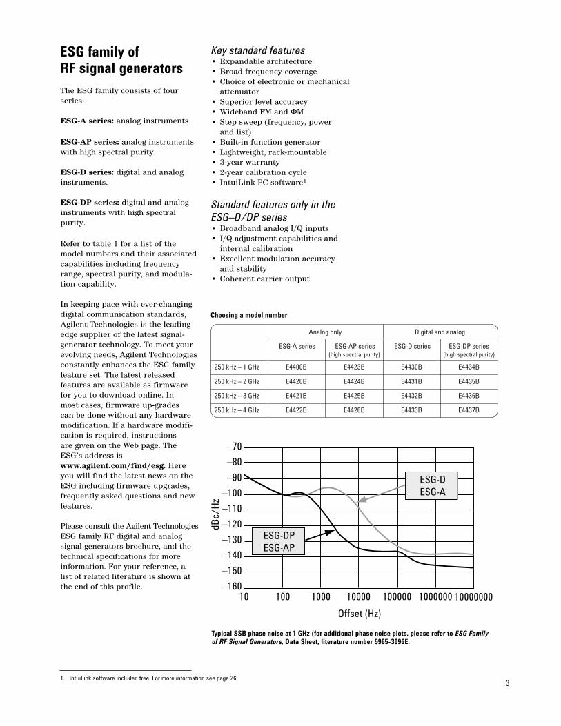
ESG-DPESG-AP
ESG-DESG-A
Choosing a model number
Typical SSB phase noise at 1 GHz (for additional phase noise plots, please refer to ESG Family of RF Signal Generators, Data Sheet, literature number 5965-3096E.
1. IntuiLink software included free. For more information see page 26.
4
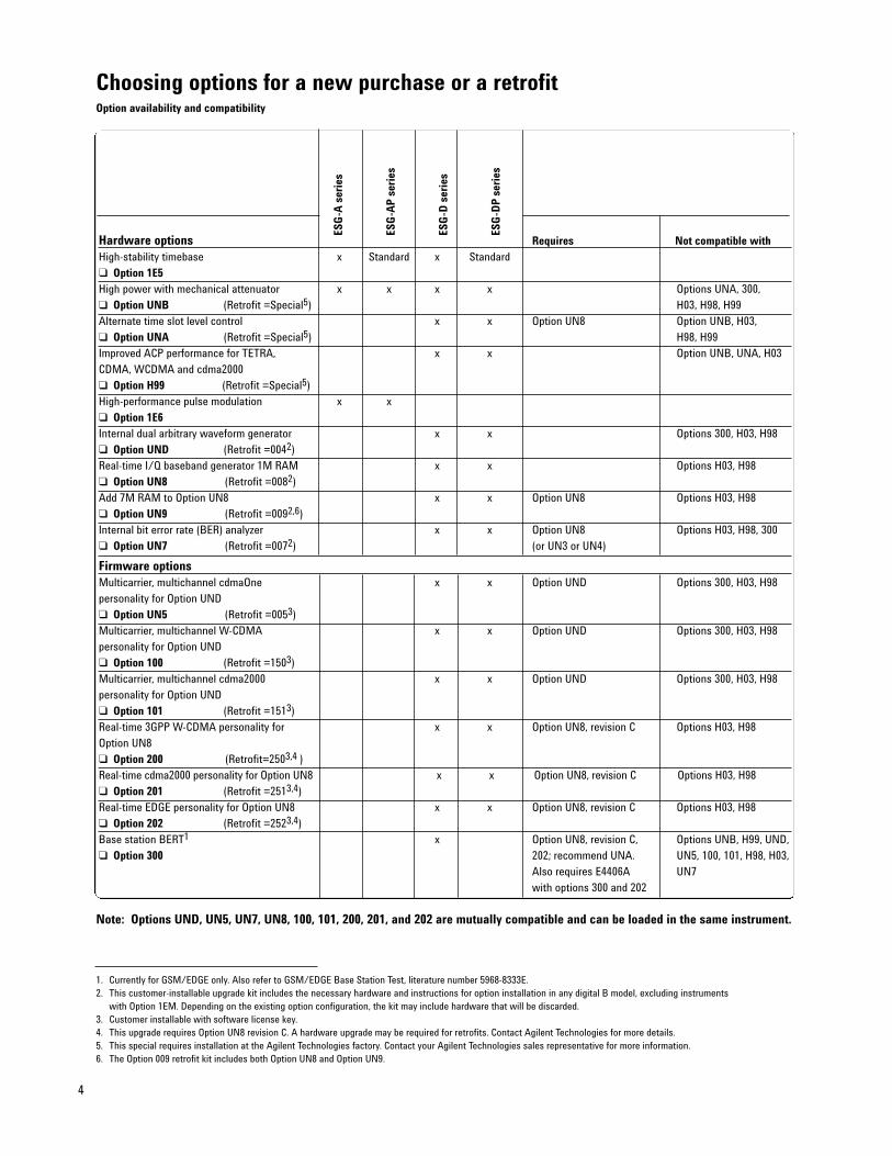
Hardware options Requires Not compatible withHigh-stability timebase x Standard x Standard
Option 1E5 High power with mechanical attenuator x x x x Options UNA, 300,
Option UNB (Retrofit =Special5) H03, H98, H99
Alternate time slot level control x x Option UN8 Option UNB, H03,
Option UNA (Retrofit =Special5) H98, H99
Improved ACP performance for TETRA, x x Option UNB, UNA, H03
CDMA, WCDMA and cdma2000
Option H99 (Retrofit =Special5)
High-performance pulse modulation x x
Option 1E6Internal dual arbitrary waveform generator x x Options 300, H03, H98
Option UND (Retrofit =0042)
Real-time I/Q baseband generator 1M RAM x x Options H03, H98
Option UN8 (Retrofit =0082)
Add 7M RAM to Option UN8 x x Option UN8 Options H03, H98
Option UN9 (Retrofit =0092,6)
Internal bit error rate (BER) analyzer x x Option UN8 Options H03, H98, 300
Option UN7 (Retrofit =0072) (or UN3 or UN4)
Firmware optionsMulticarrier, multichannel cdmaOne x x Option UND Options 300, H03, H98
personality for Option UND
Option UN5 (Retrofit =0053)
Multicarrier, multichannel W-CDMA x x Option UND Options 300, H03, H98
personality for Option UND
Option 100 (Retrofit =1503)
Multicarrier, multichannel cdma2000 x x Option UND Options 300, H03, H98
personality for Option UND
Option 101 (Retrofit =1513)
Real-time 3GPP W-CDMA personality for x x Option UN8, revision C Options H03, H98
Option UN8
Option 200 (Retrofit=2503,4 )
Real-time cdma2000 personality for Option UN8 x x Option UN8, revision C Options H03, H98
Option 201 (Retrofit =2513,4)
Real-time EDGE personality for Option UN8 x x Option UN8, revision C Options H03, H98
Option 202 (Retrofit =2523,4)
Base station BERT1 x Option UN8, revision C, Options UNB, H99, UND,
Option 300 202; recommend UNA. UN5, 100, 101, H98, H03,
Also requires E4406A UN7
with options 300 and 202
ESG
-A s
erie
s
ESG
-AP
seri
es
ESG
-D s
erie
s
ESG
-DP
seri
es
1. Currently for GSM/EDGE only. Also refer to GSM/EDGE Base Station Test, literature number 5968-8333E.2. This customer-installable upgrade kit includes the necessary hardware and instructions for option installation in any digital B model, excluding instruments
with Option 1EM. Depending on the existing option configuration, the kit may include hardware that will be discarded.3. Customer installable with software license key.4. This upgrade requires Option UN8 revision C. A hardware upgrade may be required for retrofits. Contact Agilent Technologies for more details.5. This special requires installation at the Agilent Technologies factory. Contact your Agilent Technologies sales representative for more information.6. The Option 009 retrofit kit includes both Option UN8 and Option UN9.
Note: Options UND, UN5, UN7, UN8, 100, 101, 200, 201, and 202 are mutually compatible and can be loaded in the same instrument.
Choosing options for a new purchase or a retrofitOption availability and compatibility
5
Internal dual arbitrarywaveform generator, Option UND
Adapt quickly to changing marketneeds with a completely flexiblebaseband generator. Download waveforms that simulate complex,non-standard or proprietary modula-tion schemes. Replay complex wave-forms to simulate multicarrierCDMA and TDMA signals to easilycharacterize base station poweramplifiers. Generate I/Q files frommany different application programs,such as Omnisys, MATLAB™, andMathcad™, and then download the waveform from an external computer through GPIB or RS-232.
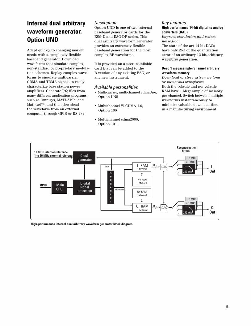
DescriptionOption UND is one of two internalbaseband generator cards for the ESG-D and ESG-DP series. This dual arbitrary waveform generatorprovides an extremely flexible baseband generation for the mostcomplex RF waveforms.
It is provided on a user-installable card that can be added to the B version of any existing ESG, or any new instrument.
Available personalities• Multicarrier, multichannel cdmaOne,
Option UN5
• Multichannel W-CDMA 1.0,Option 100
• Multichannel cdma2000, Option 101
Key featuresHigh performance 14-bit digital to analogconverters (DAC)Improve simulation and reduce noise floor. The state of the art 14-bit DACs have only 25% of the quantizationerror of an ordinary 12-bit arbitrarywaveform generation.
Deep 1 megasample/channel arbitrarywaveform memoryDownload or store extremely long or numerous waveforms.Both the volatile and nonvolatile RAM have 1 Megasample of memory per channel. Switch between multiplewaveforms instantaneously to minimize valuable download time in a manufacturing environment.
Clockgenerator
Digitalsignal
processor
Sequencer
I RAM1 MWord
GPIB MainCPU
Q RAM1 MWord
10 MHz internal reference1 to 20 MHz external reference
DAC
DAC
Reconstructionfilters
14
14data
NV RAM1MWord
NV RAM1MWord
addresses
QOut
MHz
8 MHz
250 kHz
2.5 MHz
IOut
MHz
8 MHz
250 kHz
2.5 MHz
High-performance internal dual arbitrary waveform generator block diagram.
6
Option UND (continued)
Multitone1
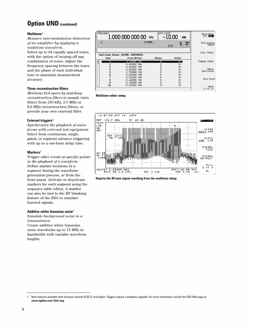
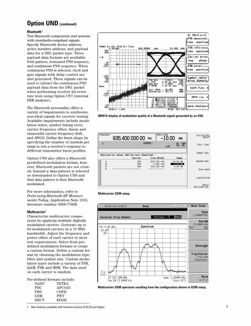
Measure intermodulation distortionof an amplifier by applying a multitone waveform. Select up to 64 equally spaced tones,with the option of turning off any combination of tones. Adjust the frequency spacing between the tonesand the phase of each individualtone to maximize measurementaccuracy.
Three reconstruction filtersMinimize D/A spurs by matchingreconstruction filters to sample rates.Select from 250 kHz, 2.5 MHz or 8.0 MHz reconstruction filters, or provide your own external filter.
External triggers1
Synchronize the playback of wave-forms with external test equipment.Select from continuous, single,gated, or segment advance triggeringwith up to a one-hour delay time.
Markers1
Trigger other events at specific pointsin the playback of a waveform.Define marker locations in a segment during the waveform-generation process, or from the front panel. Activate or deactivatemarkers for each segment using thesequence table editor. A marker can also be tied to the RF blankingfeature of the ESG to simulate bursted signals.
Additive white Gaussian noise1
Simulate background noise in atransmission.Create additive white Gaussian noise waveforms up to 15 MHz in bandwidth with variable waveformlengths.
Multitone editor setup.
Depicts the 64 tone signal resulting from the multitone setup.
1. New features available with firmware revision B.02.21 and higher. Triggers require a hardware upgrade. For more information consult the ESG Web page atwww.agilent.com/find/esg.
7
Option UND (continued)
Bluetooth1
Test Bluetooth components and systemswith standards-compliant signals.Specify Bluetooth device address,active member address, and payloaddata for a DH1 packet type. Threepayload data formats are available: 8-bit pattern, truncated PN9 sequence,and continuous PN9 sequence. Whencontinuous PN9 is selected, clock andgate signals with delay control arealso generated. These signals can beused to extract the continuous PN9payload data from the DH1 packetwhen performing receiver bit-error-rate tests using Option UN7 (internalBER analyzer).
The Bluetooth personality offers avariety of impairments to synthesizenon-ideal signals for receiver testing.Available impairments include modu-lation index, symbol timing error,carrier frequency offset, linear andsinusoidal carrier frequency drift, and AWGN. Define the burst shape byspecifying the number of symbols perramp to test a receiver’s response todifferent transmitter burst profiles.
Option UN8 also offers a Bluetoothpredefined modulation format, how-ever, Bluetooth packets are not creat-ed. Instead a data pattern is selectedor downloaded to Option UN8 andthat data pattern is then Bluetoothmodulated.
For more information, refer toPerforming Bluetooth RF Measure-ments Today, Application Note 1333,literature number 5968-7746E.
Multicarrier1
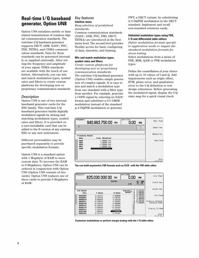
Characterize multicarrier compo-nents by applying multiple digitallymodulated carriers. Generate up to64 modulated carriers in a 15 MHzbandwidth. Adjust the frequency andpower offset of each carrier to meettest requirements. Select from pre-defined modulation formats or createa custom format. Define a custom for-mat by choosing the modulation type,filter and symbol rate. Custom modu-lation types include a variety of PSK,QAM, FSK and MSK. The data usedon each carrier is random.
Pre-defined formats include:NADC TETRAPDC APCO25PHS CDPDGSM PWT DECT EDGE
89441A display of modulation quality of a Bluetooth signal generated by an ESG.
Multicarrier GSM setup.
Multicarrier GSM spectrum resulting from the configuration shown in GSM setup.
1. New features available with firmware revision B.03.20 and higher.
8
Real-time I/Q baseband generator, Option UN8Option UN8 simulates mobile or basestation transmissions of common digi-tal communication standards. Thereal-time I/Q baseband generatorsupports DECT, GSM, NADC, PDC,PHS, TETRA, and CDMA communi-cation standards. Data for thesestandards can be generated internal-ly or supplied externally. After set-ting the frequency and amplitude of your signal, TDMA standards are available with the touch of onebutton. Alternatively, you can mixand match modulation types, symbolrates and filters to create customplatforms for developing new or proprietary communication standards.
DescriptionOption UN8 is one of two internal baseband generator cards for the ESG family. This real-time I/Q baseband generator builds digitallymodulated signals by mixing andmatching modulation types, symbolrates and filters. It is provided on a user-installable card that can beadded to the B version of any existingESG or any new instrument.
Different personalities may be purchased separately to provide specific modulation formats.
Option UN8 is a standard optionwith 1 Megabyte of RAM to storecustom data. To increase the RAM to 8 Megabytes, Option UN8 can beordered in conjunction with OptionUN9 (Option UN8 consists of twocards). Option UN9 replaces one ofthese cards to provide 8 Megabytes of RAM.
Key featuresIntuitive menuEasy selection of predefined standards.Common communication standards(NADC, GSM, PDC, PHS, DECT,TETRA) are introduced at the firstmenu level. The second level providesflexible access for basic configuringof data, timeslots, and framing.
Mix and match modulation types, symbol rates and filtersCreate custom platforms for developing new or proprietary communication standards.The real-time I/Q baseband generator(Option UN8) enables simple genera-tion of complex signals. It is easy tomix and match a modulation typefrom one standard with a filter typefrom another. For example, generatea CDPD signal by selecting an NADCformat and substitute a 0.5 GMSK modulation instead of the standardp/4 DQPSK modulation or generate
PWT, a DECT variant, by substitutingπ/4 DQPSK modulation in the DECTstandard. Implement and recall non-standard solutions easily.
Unlimited modulation types using FSK,I/Q and differential table editorsDefine modulation formats specific to application needs or impair the standard modulation formats forstress testing.Select modulations from a menu ofPSK, MSK, QAM or FSK modulationtypes.
Define the constellation of your choicewith up to 16 values of I and Q. Addimpairments such as origin offset,EVM, phase error, and quadratureerror to the I/Q definition to testdesign robustness. Before generatingthe modulated signal, display the I/Qstate map for a quick visual check.
You can build asymmetric FSK formats such as FLEX with the FSK table editor.
Customize modulations or perform margin testing with the I/Q table editor.
9
Option UN8 (continued)
Symbol rates up to 12.5 MHzSpecify rates to cover the existingcommunications systems and newthird-generation systems.If you want to create a new modula-tion scheme, the real-time I/Q baseband generator symbol rate can be specified from 50 Hz to 12.5 MHz. This range covers existingcommunications systems such asGSM at 270.833 Ksps and NADC at24.3 Ksps and new emerging wide-band communication systems.
Internal data generatorGenerate PN (pseudo-random noise)sequences or repeating patterns.Internally generate PN9, PN11,PN15, PN20 and PN23 (pseudo-random noise) sequences or fixed 4- to 64-bit repeating patterns. Otherdata patterns can be downloadedinto memory or generated in real-time,through the data/clock/sync inputs.
Burst shapingCreate custom burst to simulateunique traffic patterns. Adjust burst rise/fall time and delaythrough softkeys under the chosenTDMA protocol. Customized or standard bursts may also be provided externally through the external 1 input.
Unlimited baseband filteringSelect or build your own filters tocontrol bandwidth and modulationquality. Nyquist, root Nyquist, Gaussian andIS-95 FIR filters are all available.Specify the filter alpha from 0 to 1or the BT (bandwidth time product)for a Gaussian filter from 0.1 to 1.
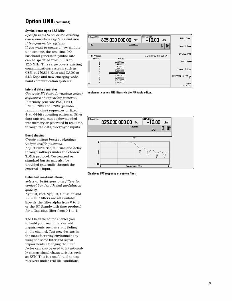
The FIR table editor enables you to build your own filters or addimpairments such as static fading in the channel. Test new designs inthe manufacturing environment byusing the same filter and signalimpairments. Changing the filter factor can also be used to intentional-ly change signal characteristics suchas EVM. This is a useful tool to testreceivers under real-life conditions.
Implement custom FIR filters via the FIR table editor.
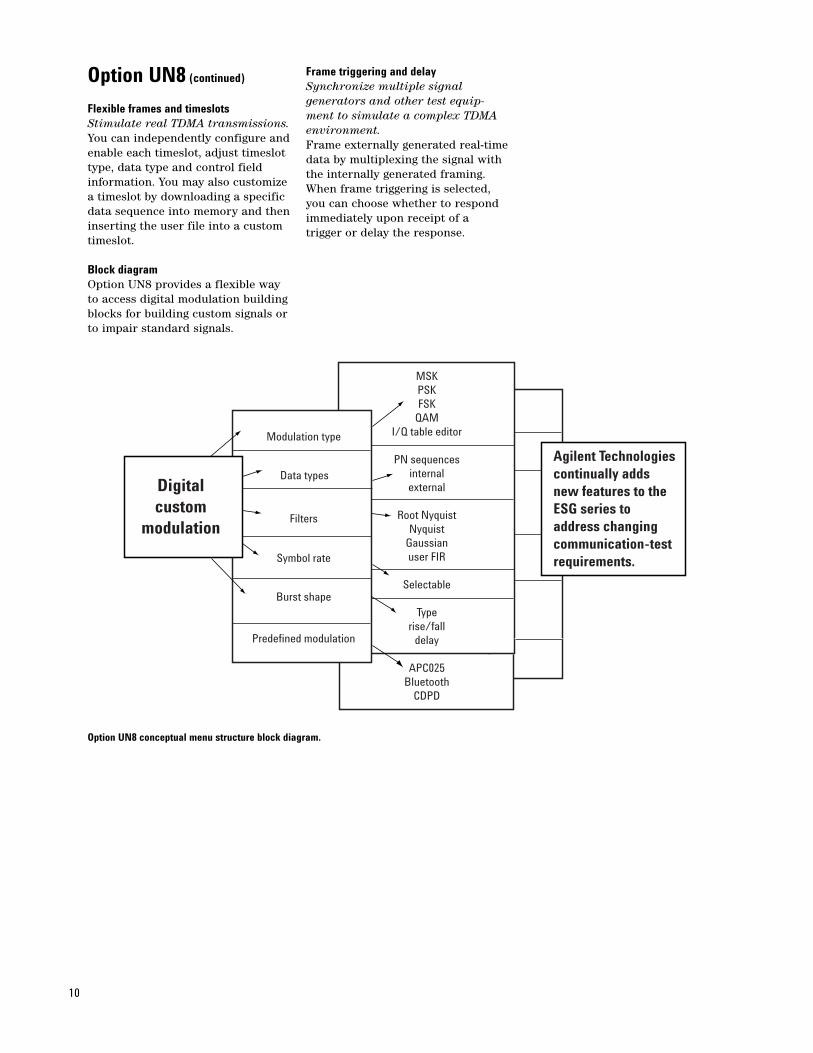
Displayed FFT response of custom filter.
10
Option UN8 (continued)
Flexible frames and timeslotsStimulate real TDMA transmissions. You can independently configure andenable each timeslot, adjust timeslottype, data type and control field information. You may also customize a timeslot by downloading a specificdata sequence into memory and theninserting the user file into a customtimeslot.
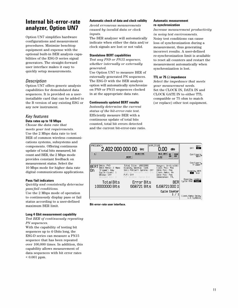
Block diagram Option UN8 provides a flexible way to access digital modulation buildingblocks for building custom signals or to impair standard signals.
Frame triggering and delaySynchronize multiple signal generators and other test equip-ment to simulate a complex TDMAenvironment. Frame externally generated real-timedata by multiplexing the signal with the internally generated framing. When frame triggering is selected, you can choose whether to respondimmediately upon receipt of a trigger or delay the response.
Option UN8 conceptual menu structure block diagram.
Agilent Technologiescontinually addsnew features to the ESG series to address changingcommunication-testrequirements.
MSKPSKFSK
QAMI/Q table editor
PN sequencesinternalexternal
Root NyquistNyquist
Gaussianuser FIR
Selectable
Typerise/fall
delay
APC025Bluetooth
CDPD
Modulation type
Data types
Filters
Symbol rate
Burst shape
Predefined modulation
Digitalcustom
modulation
Internal bit-error-rateanalyzer, Option UN7Option UN7 simplifies hardware configurations and measurement procedures. Minimize benchtopequipment and expense with theoptional built-in BER analysis capa-bilities of the ESG-D series signalgenerators. The straight-forwarduser interface makes it easy toquickly setup measurements.
DescriptionOption UN7 offers generic analysiscapabilities for demodulated datasequences. It is provided on a user-installable card that can be added tothe B version of any existing ESG orany new instrument.
Key featuresData rates up to 10 MbpsChoose the data rate thatmeets your test requirements.Use the 2 Mbps data rate to test BER of common wireless communi-cations systems, subsystems andcomponents. Offering continuousupdate of total bits measured, bitcount and BER, the 2 Mbps mode provides constant feedback on measurement status. Select the 10 Mbps mode for higher data ratedigital communications applications.
Pass/fail indicatorsQuickly and consistently determine pass/fail conditions. Use the 2 Mbps mode of operation to continuously display pass or failstatus according to a user-definedmaximum BER limit.
Long 4 Gbit measurement capabilityTest BER of continuously repeatingPN sequences.With the capability of testing bitsequences up to 4 Gbits long, the ESG-D series can measure a PN15sequence that has been repeatedover 100,000 times. In addition, thiscapability allows measurement ofdata sequences with bit error rates < 0.001 ppm.
Automatic check of data and clock validityAvoid erroneous measurements caused by invalid data or clock inputs. The BER analyzer will automaticallyindicate when either the data and/orclock signals are lost or not valid.
Standalone BERT capabilitiesTest any PN9 or PN15 sequence,whether internally or externally generated. Use Option UN7 to measure BER ofexternally generated PN sequences.The ESG-D with the BER analysisoption will automatically synchronizeon PN9 or PN15 sequences clockedin at the appropriate data rate.
Continuously updated BERT resultsInstantly determine the current status of the bit-error-rate test. Efficiently measure BER with a continuous update of total bits counted, total bit errors detected and the current bit-error-rate ratio.
Automatic measurementre-synchronizationIncrease measurement productivityin noisy test environments.Noisy test conditions can cause loss of synchronization during a measurement, thus generating incorrect results. A user-defined re-synchronization limit is available to reset all counters and restart themeasurement automatically whensynchronization is lost.
TTL or 75 Ω impedanceSelect the impedance that meets your measurement needs.Set the CLOCK IN, DATA IN andCLOCK GATE IN to either TTL compatible or 75 ohm to match (or replace) other test equipment.
Bit-error-rate user interface.
11
12
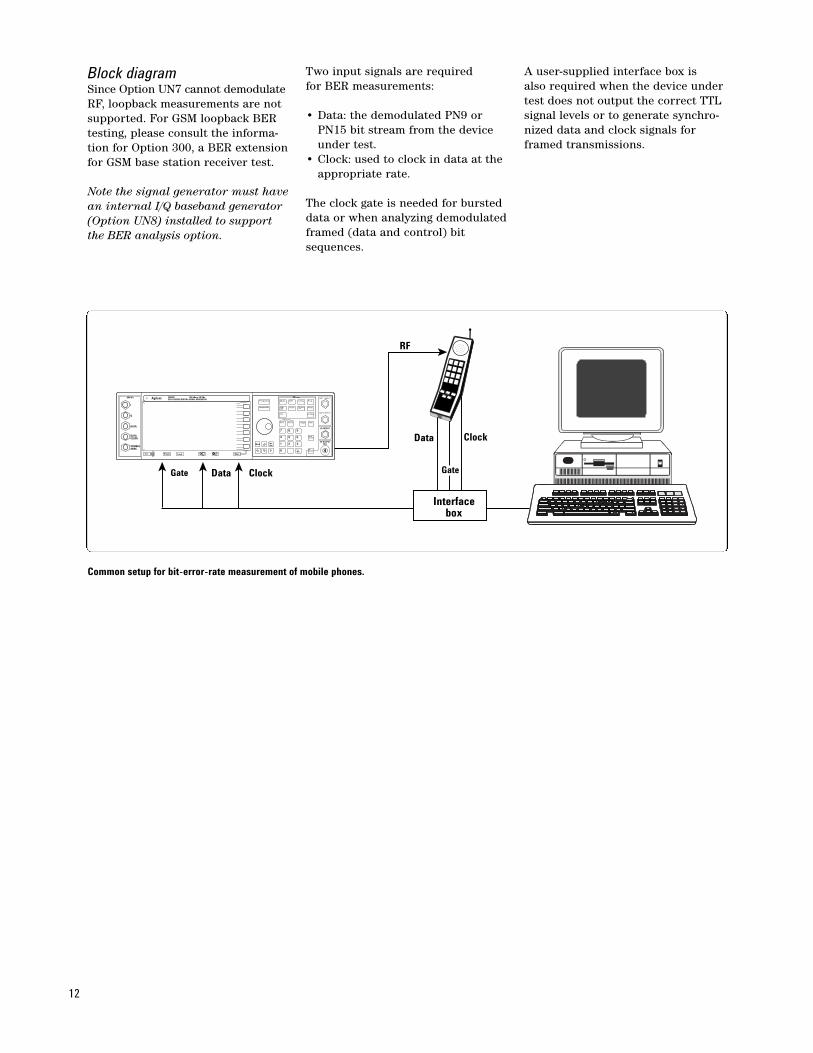
Block diagram Since Option UN7 cannot demodulateRF, loopback measurements are notsupported. For GSM loopback BERtesting, please consult the informa-tion for Option 300, a BER extensionfor GSM base station receiver test.
Note the signal generator must havean internal I/Q baseband generator(Option UN8) installed to supportthe BER analysis option.
Two input signals are required for BER measurements:
• Data: the demodulated PN9 or PN15 bit stream from the device under test.
• Clock: used to clock in data at the appropriate rate.
The clock gate is needed for bursteddata or when analyzing demodulatedframed (data and control) bitsequences.
A user-supplied interface box is also required when the device undertest does not output the correct TTLsignal levels or to generate synchro-nized data and clock signals forframed transmissions.
Data Clock
GateClockGate Data
RF
Interface box
INPUT
I
Q
DATA
DATACLOCK
SYMBOLSYNC
Preset Local More
More Inc.Set
MenusE4433B 250 kHz to 4.0 GHzESG-D SERIES DIGITAL SIGNAL GENERATOR
LF OUTPUT
RF OUTPUT50Ω
Common setup for bit-error-rate measurement of mobile phones.
13
GSM/EDGEbase station BERT Option 300 (includesbaseband BER testing)ETSI compliant receiver testing forGSM/EDGE base stations is nowavailable on the ESG platform.Option 300 provides basic measure-ment modes for GSM base stationtest, such as BER and sensitivitysearch.
Option 300 also provides basic mea-surement modes for EDGE/EGPRSbase station test, such as,BER/BLER and sensitivity measure-ments.
The E4406A VSA transmitter testerconveniently provides the requiredexternal down conversion while fulfilling the transmitter test needs.The chosen implementation of RFloop back permits device indepen-dent test of base station and basetransceiver modules.
DescriptionOption 300 requires UN8 revision C,real-time I/Q baseband generator.Option 202, EDGE personality, is required for EDGE BTS test functions. Option UNA, alternatetime slot level control, is highly recommended. Option 300 alsorequires an external down converter.The E4406A VSA can provide thisrequirement. An ordering conve-nience bundle combines the E4406AVSA and ESG configured for GSMand GSM/EDGE base station transmitter and receiver tests. These numbers are as follows:
Bundle Contents:
GSM BTS test: E4433Z Option 301E4433B ESG (4 GHz)#UN8 (real-time I/Q baseband generator)#300 (includes baseband BER tester)#UNA (alternate time slot level control)#1CP (rackmount and handle kit)#1E5 (high-stability timebase)E4406A VSA#BAH (GSM measurement personality)#300 (321.4 MHz output)#1CP (rackmount and handle kit)
GSM/EDGE BTS test: E4433Z Option 302E4433B ESG (4 GHz)#UN8 (real-time I/Q baseband generator)#300 (includes baseband BER tester)#202 (EDGE personality)#UNA (alternate time slot level control)#1CP (rackmount and handle kit)#1E5 (high-stability timebase)E4406A VSA#202 (GSM and EDGE measurementpersonality)#300 (321.4 MHz output)#1CP (rackmount and handle kit)
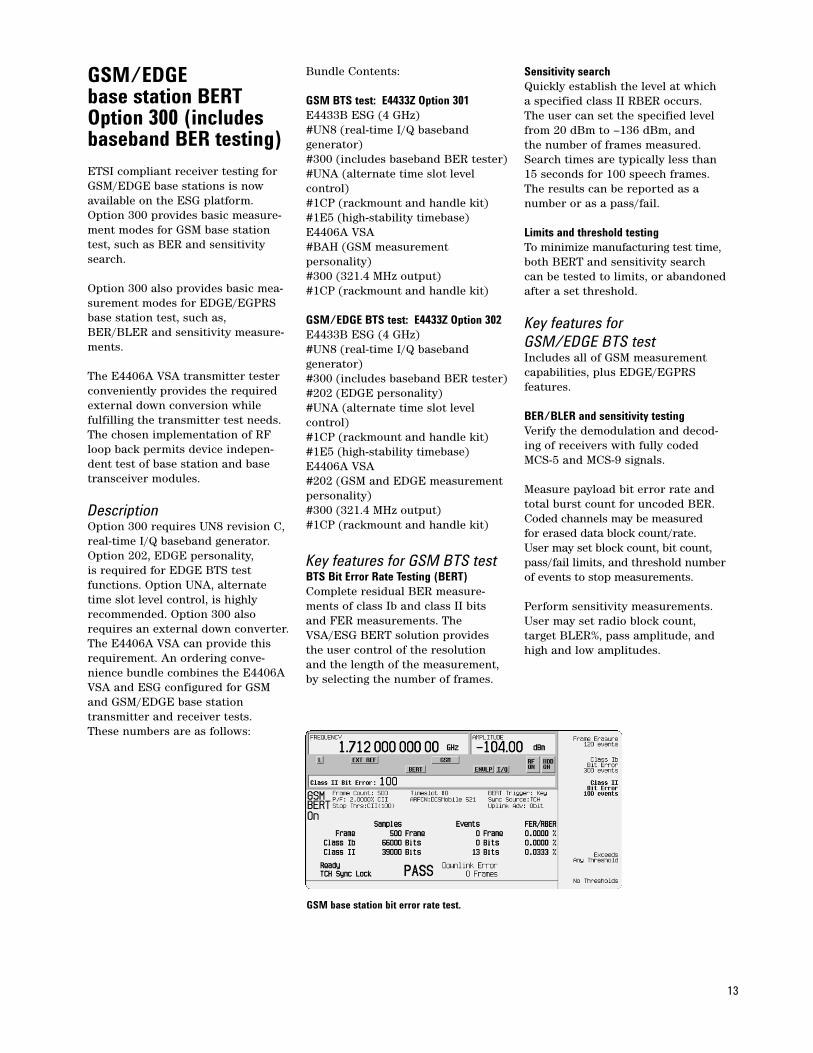
Key features for GSM BTS testBTS Bit Error Rate Testing (BERT)Complete residual BER measure-ments of class Ib and class II bitsand FER measurements. TheVSA/ESG BERT solution providesthe user control of the resolutionand the length of the measurement,by selecting the number of frames.
Sensitivity searchQuickly establish the level at which a specified class II RBER occurs. The user can set the specified levelfrom 20 dBm to –136 dBm, and the number of frames measured.Search times are typically less than15 seconds for 100 speech frames.The results can be reported as anumber or as a pass/fail.
Limits and threshold testingTo minimize manufacturing test time,both BERT and sensitivity searchcan be tested to limits, or abandonedafter a set threshold.
Key features for GSM/EDGE BTS testIncludes all of GSM measurementcapabilities, plus EDGE/EGPRS features.
BER/BLER and sensitivity testingVerify the demodulation and decod-ing of receivers with fully codedMCS-5 and MCS-9 signals.
Measure payload bit error rate andtotal burst count for uncoded BER.Coded channels may be measured for erased data block count/rate. User may set block count, bit count,pass/fail limits, and threshold numberof events to stop measurements.
Perform sensitivity measurements.User may set radio block count, target BLER%, pass amplitude, andhigh and low amplitudes.
GSM base station bit error rate test.
14
Baseband BER testingOption 300 includes baseband BERtesting (cannot be ordered separate-ly). BER simplifies hardware configurations and measurementprocedures. Minimize benchtopequipment and expense with theoptional built-in BER analysis capabilities of the ESG-D series signal generators. The straight-forward user interface makes it easy to quickly setup measurements.
DescriptionBER offers generic analysis capabili-ties for demodulated data sequences.
Key featuresData rates up to 10 MbpsChoose the data rate that meets your testrequirements.Use the 2 Mbps data rate to test BER of common wireless communi-cations systems, subsystems andcomponents. Offering continuousupdate of total bits measured, bitcount and BER, the 2 Mbps modeprovides constant feedback onmeasurement status. Select the 10 Mbps mode for higher data ratedigital communications applications.
Pass/fail indicatorsQuickly and consistently determinepass/fail conditions.Use the 2 Mbps mode of operation to continuously display pass or failstatus according to a user-definedmaximum BER limit.
Long 4 Gbit measurement capabilityTest BER of continuously repeatingPN sequences.With the capability of testing bitsequences up to 4 Gbits long, theESG-D series can measure a PN15sequence that has been repeatedover 100,000 times. In addition, this capability allows measurementof data sequences
Automatic check of data and clock validityAvoid erroneous measurementscaused by invalid data or clockinputs.The BER tester will automaticallyindicate when either the data and/orclock signals are lost or not valid.
Standalone BER testing capabilitiesTest any PN9 or PN15 sequence,whether internally or externallygenerated.Use the baseband BER tester to mea-sure BER of externally generated PNsequences. The ESG-D with the BERtester will automatically synchronizeon PN9 or PN15 sequences clockedin at the appropriate data rate.
Continuously updated BER test resultsInstantly determine the current status of the bit error rate test.Efficiently measure BER with a continuous update of total bitscounted, total bit errors detectedand the current bit error rate ratio.
Automatic measurement re-synchronizationIncrease measurement productivityin noisy test environments.Noisy test conditions can cause loss of synchronization during ameasurement, thus generating incorrect results. A user-defined re-synchronization limit is availableto reset all counters and restart themeasurement automatically whensynchronization is lost.
TTL or 75 impedanceSelect the impedance that meetsyour measurement needs.Set the CLOCK IN, DATA IN andCLOCK GATE IN to either TTL compatible or 75 ohm to match (orreplace) other test equipment.
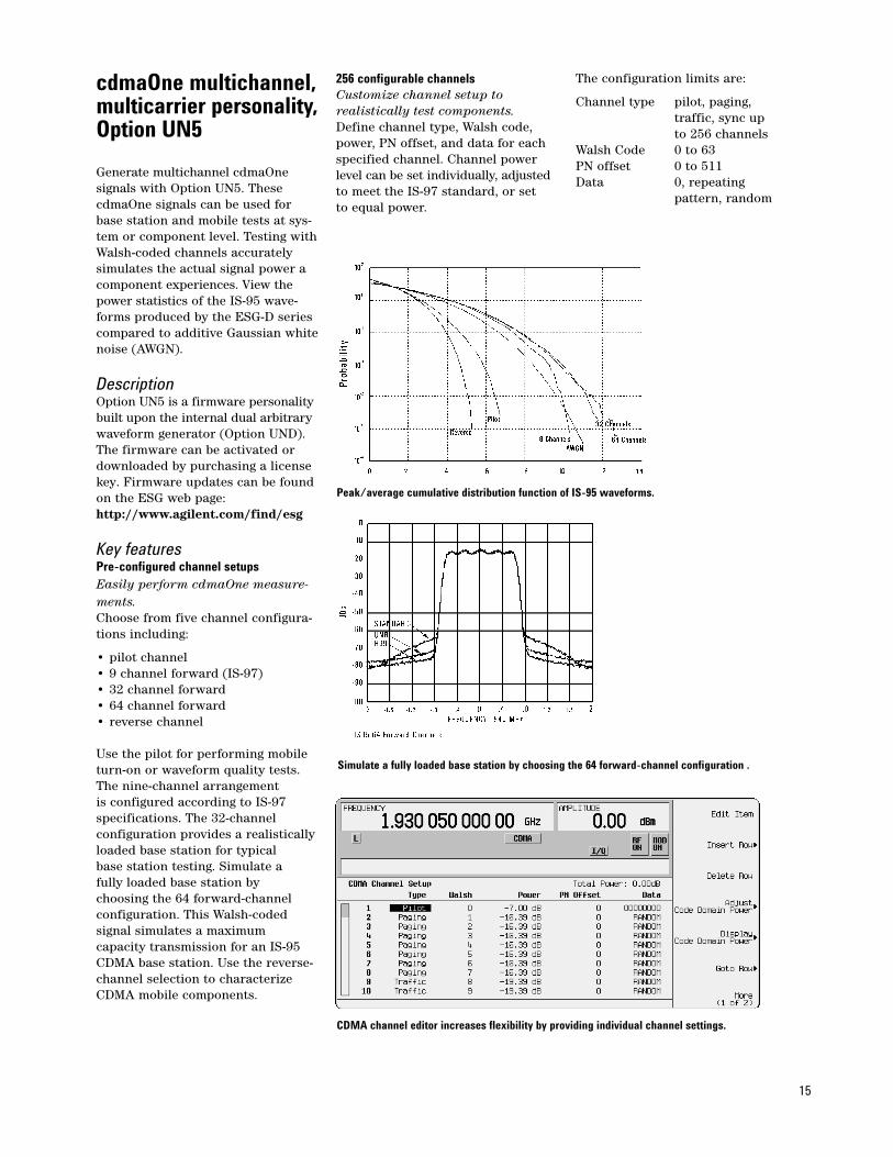
Baseband BER tester user interface.
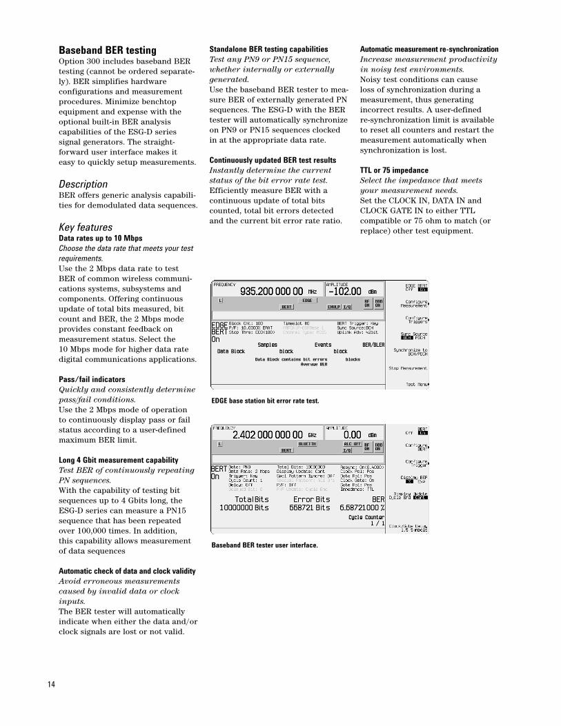
EDGE base station bit error rate test.
15
cdmaOne multichannel,multicarrier personality,Option UN5
Generate multichannel cdmaOnesignals with Option UN5. ThesecdmaOne signals can be used forbase station and mobile tests at sys-tem or component level. Testing withWalsh-coded channels accuratelysimulates the actual signal power acomponent experiences. View thepower statistics of the IS-95 wave-forms produced by the ESG-D seriescompared to additive Gaussian whitenoise (AWGN).
DescriptionOption UN5 is a firmware personalitybuilt upon the internal dual arbitrarywaveform generator (Option UND).The firmware can be activated ordownloaded by purchasing a licensekey. Firmware updates can be found on the ESG web page:http://www.agilent.com/find/esg
Key featuresPre-configured channel setupsEasily perform cdmaOne measure-ments.Choose from five channel configura-tions including:
• pilot channel• 9 channel forward (IS-97)• 32 channel forward• 64 channel forward• reverse channel
Use the pilot for performing mobileturn-on or waveform quality tests. The nine-channel arrangement is configured according to IS-97 specifications. The 32-channel configuration provides a realisticallyloaded base station for typical base station testing. Simulate a fully loaded base station by choosing the 64 forward-channelconfiguration. This Walsh-coded signal simulates a maximum capacity transmission for an IS-95CDMA base station. Use the reverse-channel selection to characterizeCDMA mobile components.
256 configurable channelsCustomize channel setup to realistically test components.Define channel type, Walsh code,power, PN offset, and data for eachspecified channel. Channel power level can be set individually, adjustedto meet the IS-97 standard, or set to equal power.
The configuration limits are:
Channel type pilot, paging, traffic, sync up to 256 channels
Walsh Code 0 to 63PN offset 0 to 511Data 0, repeating
pattern, random
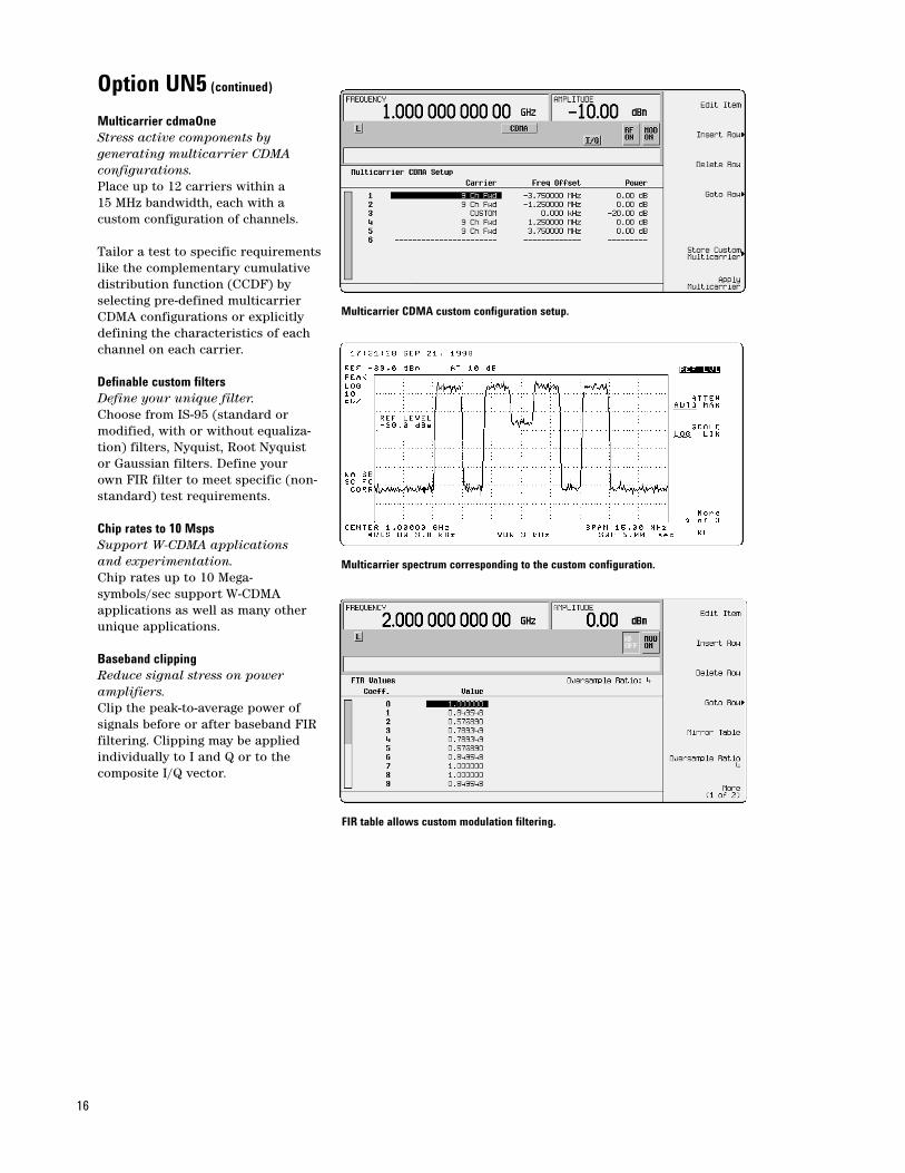
Peak/average cumulative distribution function of IS-95 waveforms.
Simulate a fully loaded base station by choosing the 64 forward-channel configuration .
CDMA channel editor increases flexibility by providing individual channel settings.
16
Option UN5 (continued)
Multicarrier cdmaOneStress active components by generating multicarrier CDMA configurations.Place up to 12 carriers within a 15 MHz bandwidth, each with a custom configuration of channels.
Tailor a test to specific requirementslike the complementary cumulative distribution function (CCDF) byselecting pre-defined multicarrierCDMA configurations or explicitlydefining the characteristics of eachchannel on each carrier.
Definable custom filtersDefine your unique filter.Choose from IS-95 (standard or modified, with or without equaliza-tion) filters, Nyquist, Root Nyquistor Gaussian filters. Define your own FIR filter to meet specific (non-standard) test requirements.
Chip rates to 10 MspsSupport W-CDMA applications and experimentation.Chip rates up to 10 Mega-symbols/sec support W-CDMA applications as well as many otherunique applications.
Baseband clippingReduce signal stress on poweramplifiers.Clip the peak-to-average power of signals before or after baseband FIRfiltering. Clipping may be appliedindividually to I and Q or to thecomposite I/Q vector.
Multicarrier CDMA custom configuration setup.
Multicarrier spectrum corresponding to the custom configuration.
FIR table allows custom modulation filtering.

17
Option UN5 (continued)
Code domain power displayVisually check channel configuration.Prevent mistakes and costly delays by checking the expected channelsetup before producing the RF signal.
Block diagramOption UN5 partially coded IS-95 provides the highlighted section of the physical layer for forward trafficchannels. Option UN5 also includesa single reverse channel beginningwith short code spreading.
Code domain power view.
Long code
64-arymodulatorReverse link
Vecodedspeach data
Convolutionalencoder
Walsh codesequence
Long code
Forward link
Q short code
I short code
Data in:• all 0's• repeating pattern• random
FIR
FIRt/2
QPSK
OQPSK1/2 chip delay
1.2288Mbps
Not in UN5 Coding in UN5
I
Q
Sums up to256 channels
64 channels
Interleaver
Σ
Σ
Physical layer of CDMA standard block diagram.
18
3GPP W-CDMA multi-channel, multicarrierpersonality, Option 100
DescriptionOption 100 is a firmware personalitybuilt on the internal dual arbitrarywaveform generator (Option UND).Users can generate both uplink and downlink signals that conformwith 3GPP standards. These W-CDMAsignals are suitable for component,subsystem, mobile, and base stationtests.
Key featuresConforms with 3GPP. In addition,this new feature set coexists withthe earlier ARIB (1.0-1.2) feature set,so users have access to either set.
Supports the 3.84 Mcps chip rate. In addition, it is possible to vary thisrate by +/-10%, in order to simulateclock drift between systems.
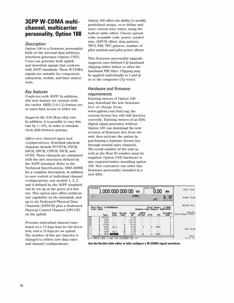
Offers new channel types and configurations. Downlink physicalchannels include PCCPCH, PSCH,SSCH, DPCH, CPICH, PICH, andOCNS. These channels are simulatedwith the slot structures defined bythe 3GPP standard. Refer to theTechnical Specifications, 5965-3096Efor a complete description. In additionto user control of individual channel configurations, test models 1, 2, 3,and 4 defined by the 3GPP standard,can be set up at the press of a but-ton. This option also offers multicar-rier capability on the downlink, andup to six Dedicated Physical DataChannels (DPDCH) plus a DedicatedPhysical Control Channel (DPCCH)on the uplink.
Provides individual channel ratesbased on a 7.5 ksps base for the down-link, and a 15 ksps for an uplink.The number of bits per timeslot ischanged to reflect new data ratesand channel configurations.
Option 100 offers the ability to modifypredefined setups, or to define andstore custom user states, using thebuilt-in table editor. Choose spreadcode, scramble code, power, symbolrate, τDPCH offset, data pattern,TFCI, FBI, TPC pattern, number ofpilot symbols and pilot power offsets.
This firmware personality upgradesupports user-defined I/Q basebandclipping either before or after thebaseband FIR filter. Clipping may be applied individually to I and Q or to the composite I/Q vector.
Hardware and firmware requirementsExisting owners of Option 100 may download the new firmware free of charge from:www.agilent.com/find/esg; the current license key will still functioncorrectly. Existing owners of an ESGdigital signal generator withoutOption 100 can download the newrevision of firmware free from theweb, then activate the option by purchasing a separate license keythrough normal sales channels. The serial number of the unit as well as the Host ID number must besupplied. Option UND hardware isalso required before installing option100. New customers can order thisfirmware personality installed in anew ESG.
Use the flexible table editor to fully configure a W-CDMA signal waveform.
19
cdma2000 multichannel,multicarrier personality, Option 101Generate multichannel forward andreverse link signals according to thedeveloping cdma2000 standard withOption 101. These 1X or 3X chiprate, direct or multicarrier spreadsignals can be used for base station,mobile, component, and subsystemtests. A table based channel editormaximizes flexibility.
DescriptionOption 101 is a firmware personalitybuilt on the internal dual arbitrarywaveform generator (Option UND).The firmware can be activated ordownloaded by purchasing a licensekey for users who already own UND.
Key features• Multichannel cdma2000 forward
and reverse link signals, either 1X or 3X chip rate
• Choose multicarrier or direct spreading type in forward link
• HPSK spreading/modulation type used in reverse link for IS95C radio configuration
• Select from predefined channel configurations or use the tableeditor to fully configure a cdma2000 channel configuration per your requirements
• Forward link channel types include,pilot, paging, synchronization, fundamental code and supplemental code channels
• Reverse link channel types include, pilot, dedicated control channel, fundamental code and supplemental code channel
• Each channel can be set to a separate code domain power level
• Baseband clipping; clip the peak-to-average power of signals before or after FIR filtering
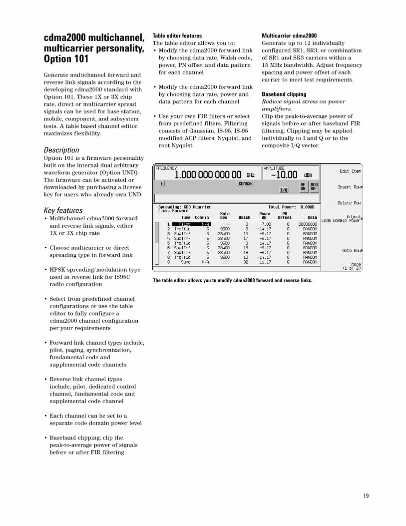
Table editor featuresThe table editor allows you to:• Modify the cdma2000 forward link
by choosing data rate, Walsh code,power, PN offset and data pattern for each channel
• Modify the cdma2000 forward link by choosing data rate, power and data pattern for each channel
• Use your own FIR filters or select from predefined filters. Filtering consists of Gaussian, IS-95, IS-95 modified ACP filters, Nyquist, and root Nyquist
Multicarrier cdma2000Generate up to 12 individually configured SR1, SR3, or combinationof SR1 and SR3 carriers within a 15 MHz bandwidth. Adjust frequencyspacing and power offset of eachcarrier to meet test requirements.
Baseband clippingReduce signal stress on poweramplifiers.Clip the peak-to-average power of signals before or after baseband FIRfiltering. Clipping may be applied individually to I and Q or to the composite I/Q vector.
The table editor allows you to modify cdma2000 forward and reverse links.
20
3GPP W-CDMA person-ality for the real-timebaseband generator,Option 200
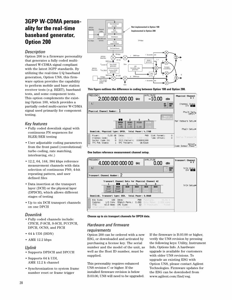
DescriptionOption 200 is a firmware personalitythat generates a fully coded multi-channel W-CDMA signal compliantwith the latest 3GPP standards. Byutilizing the real-time I/Q basebandgeneration, Option UN8, this firm-ware option provides the capabilityto perform mobile and base stationreceiver tests (e.g. BERT), basebandtests, and some component tests.This option complements the exist-ing Option 100, which provides apartially coded multi-carrier W-CDMAsignal used primarily for componenttesting.
Key features• Fully coded downlink signal with
continuous PN sequences for BLER/BER testing
• User adjustable coding parametersfrom the front panel (convolutional/turbo coding, rate matching, interleaving, etc.)
• 12.2, 64, 144, 384 kbps reference measurement channels with data selection of continuous PN9, 4-bit repeating pattern, and user defined files
• Data insertion at the transport layer (DCH) or the physical layer (DPDCH), which allows different stages of testing
• Up to six DCH transport channels on one DPCH
Downlink• Fully coded channels include:
CPICH, P-SCH, S-SCH, PCCPCH, DPCH, OCNS, and PICH
• 64 k UDI (ISDN)
• AMR 12.2 kbps
Uplink• Supports DPDCH and DPCCH
• Supports 64 k UDI, AMR 12.2 k channel
• Synchronization to system frame number reset or frame trigger
Hardware and firmware requirementsOption 200 can be ordered with a newESG, or downloaded and activated bypurchasing a license key. The serialnumber and the model of the unit, aswell as the Host ID number, must besupplied.
This personality requires enhancedUN8 revision C or higher. If theinstalled firmware revision is belowB.03.00, UN8 will need to be upgraded.
If the firmware is B.03.00 or higher,verify the UN8 revision by pressingthe following keys: Utility, InstrumentInfo, Options Info. A hardwareupgrade is available for customerswith older UN8 revisions. Toupgrade an existing ESG withOption UN8, please contact AgilentTechnologies. Firmware updates forthe ESG can be downloded fromwww.agilent.com/find/esg.
One button reference measurement channel setup.
Choose up to six transport channels for DPCH data.
DPDCHData bits
12.2 kbps 24 kbps
Ratematching
InterleaverAdd CRC and tail bits
Channel coder
Framesegmentation
Convolutional encoder
2nd Interleaver
Not implemented in Option 100
Implemented in Option 200
Gain
Pilot, powercontrol, FBI&TFCI
DPCCHData bits
15 kbps3840 kcps SF=256
Data OVSF generator
3840 kcpsSF=64
Gain
Complexscrambling
+
+
+
-1,-1
Deciby 2
I 3840 kcps
225
Scramble codegenerator
Q 3840 kcps
60 kbps
Control OVSF generator
Cch,256,0
Cch,64,16
I
I
Q
Q
DPDCHData bits
I
Q
OVSF 2generator
Scramble code
Scramble code
This figure outlines the difference in coding between Option 100 and Option 200.
21
cdma2000 personalityfor the real-time baseband generator,Option 201DescriptionOption 201cdma2000 personalityadds a fully coded, multi-channel,real-time stimulus for cdma2000mobiles and base stations to AgilentESG-D and ESG-DP (high spectralpurity) series RF signal generators.The fully coded nature of this solutionin both forward and reverse modesupports long and short codes, cyclicredundancy checks, convolutional orturbo encoding, interleaving, powercontrol, and complex scrambling.Additional capabilities allow flexiblechannel configurations with individ-ually adjustable power levels anddata rates, customizable user data,and variable chip rates. The optionis backwards compatible with IS–95Ain both the basestation and mobilesimulation modes through support of Radio Configuration 1 and 2.
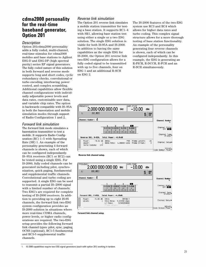
Forward link simulationThe forward link mode simulates abasestation transmitter to test amobile. It supports Radio Config-uration (RC) 1–5 with SpreadingRate (SR) 1. An example of the personality generating 4 forwardchannels is shown, each of whichcan be configured independantly.IS–95A receivers (RC1 or RC2) canbe tested using a single ESG. For IS-2000, fully coded channels can begenerated including pilot, synchro-nization, quick paging, fundamentaland supplemental traffic channels.Convolutional and turbo coding aresupported. A single ESG can be usedto transmit a partial IS–2000 signalwith a limited number of channels.Two ESG’s are required for completetesting of IS-2000 receivers. In addi-tion to providing up to eight IS-95channels, the forward link two-ESGsystem configuration provides an IS-2000 solution in situations wheremore real-time CDMA channels,power levels, or higher radio config-urations are required. The two-ESGsetup provides the following forwardlink channel types: pilot, sync, paging,OCNS (optional), RC1-5 fundamentaland RC3-5 supplemental trafficchannels.
Reverse link simulationThe Option 201 reverse link simulatesa mobile station transmitter for test-ing a base station. It supports RC1–4with SR1, allowing base station testusing either a single or a two ESGsolution. The single ESG solution isviable for both IS-95A and IS-2000.In addition to having the same capabilities as the single ESG for IS-2000, the Option 201 reverse linktwo-ESG configuration allows for afully coded signal to be transmittedwith up to five channels, four onESG 1 and an additional R-SCH on ESG 2.
The IS-2000 features of the two-ESGsystem use RC3 and RC4 whichallows for higher data rates andturbo coding. This complex signalstructure allows for a more thoroughtesting of base station functionality.An example of the personality generating four reverse channels is shown, each of which can be configured independantly. In thisexample, the ESG is generating an R-PICH, R-DCCH, R-FCH and an R-SCH simultaneously.
Forward link channel setup.
Reverse link channel setup.
1. IS-2000 capabilities require two ESG signal generators (each with option 201) working in tandem.
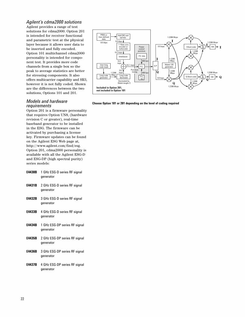
Agilent’s cdma2000 solutions Agilent provides a range of test solutions for cdma2000. Option 201is intended for receiver functionaland parametric test at the physicallayer because it allows user data tobe inserted and fully encoded.Option 101 multichannel cdma2000personality is intended for compo-nent test. It provides more codechannels from a single box so thepeak to average statistics are betterfor stressing components. It alsooffers multicarrier capability and SR3,however it is not fully coded. Shownare the differences between the twosolutions, Options 101 and 201.
Models and hardware requirementsOption 201 is a firmware personalitythat requires Option UN8, (hardwarerevision C or greater), real-timebaseband generator to be installed in the ESG. The firmware can beactivated by purchasing a licensekey. Firmware updates can be foundon the Agilent ESG Web page at,http://www.agilent.com/find/esg.Option 201, cdma2000 personality isavailable with all the Agilent ESG-Dand ESG-DP (high spectral purity)series models:
E4430B 1 GHz ESG-D series RF signal generator
E4431B 2 GHz ESG-D series RF signal generator
E4432B 3 GHz ESG-D series RF signal generator
E4433B 4 GHz ESG-D series RF signal generator
E4434B 1 GHz ESG-DP series RF signal generator
E4435B 2 GHz ESG-DP series RF signal generator
E4436B 3 GHz ESG-DP series RF signal generator
E4437B 4 GHz ESG-DP series RF signal generator
22
Σ
ΣI
I
II
Add CRC andtail bits
PRBS orUser-defined
data9.6 kbps
8.6 kbps
19.2 ksps
Interleaver
User longcode mask
Long codegenerator
19.2 ksps
19.2 ksps
19.2 ksps1.2288
Mbps Long code decimater
Decimated by Walsh length/2
Powercontrol
puncture
P.C. bits
P.C.
P.C. dec
800 bps
800 bps
S-P
9.6 ksps
9.6 ksps
1.2288 Mcps
1.2288 Mcps
1.2288 Mbps
1.2288 Mbps
1.2288 Mcps
1.2288 Mcps
1.2288 Mcps
1.2288 Mcps
Walsh 128generator
I Short code
Q Short code
FIR
FIR
1/2 Rate conv.encoder or turbocoder
Q
Q
+
–
+
–
Puncturetiming
Included in Option 201,not included in Option 101
Choose Option 101 or 201 depending on the level of coding required
23
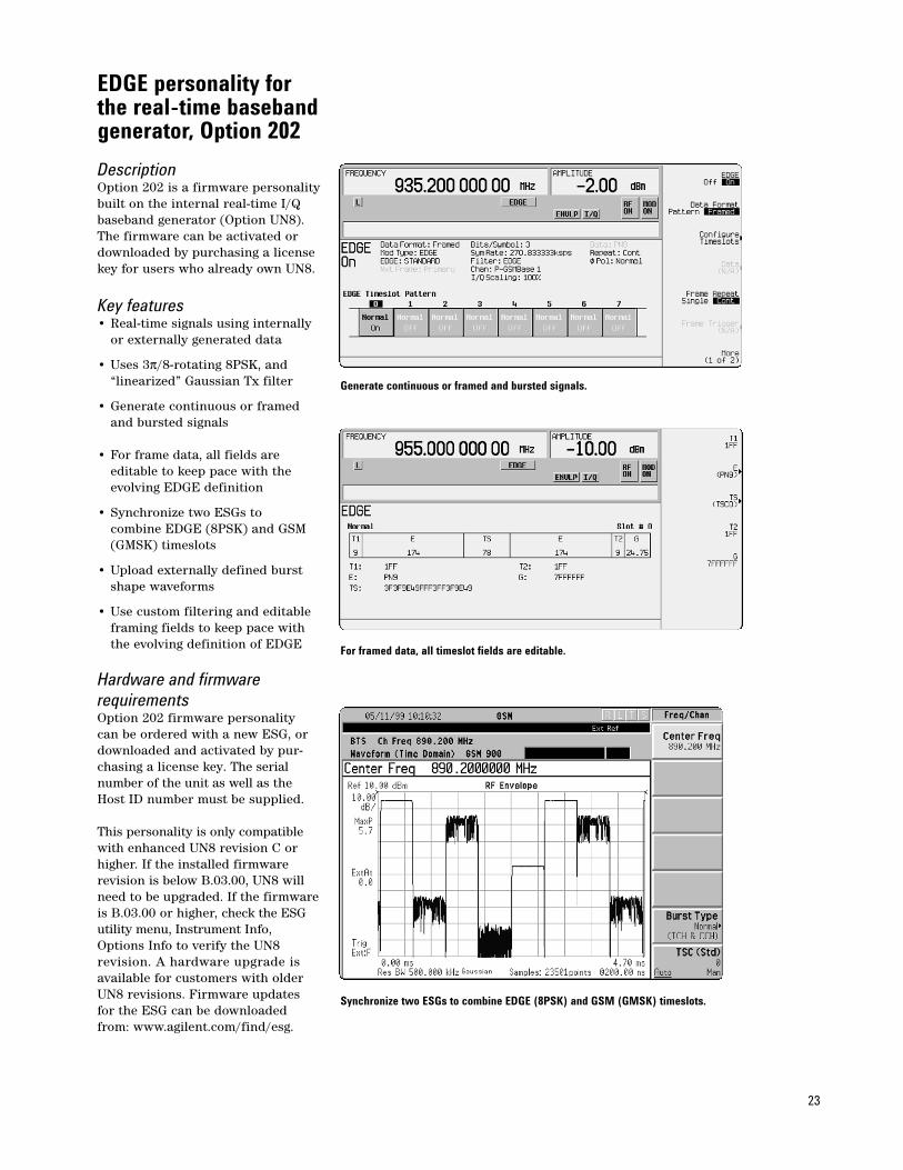
EDGE personality forthe real-time basebandgenerator, Option 202
DescriptionOption 202 is a firmware personalitybuilt on the internal real-time I/Qbaseband generator (Option UN8). The firmware can be activated ordownloaded by purchasing a licensekey for users who already own UN8.
Key features• Real-time signals using internally
or externally generated data
• Uses 3π/8-rotating 8PSK, and “linearized” Gaussian Tx filter
• Generate continuous or framed and bursted signals
• For frame data, all fields are editable to keep pace with the evolving EDGE definition
• Synchronize two ESGs to combine EDGE (8PSK) and GSM (GMSK) timeslots
• Upload externally defined burst shape waveforms
• Use custom filtering and editable framing fields to keep pace with the evolving definition of EDGE
Hardware and firmware requirementsOption 202 firmware personality can be ordered with a new ESG, ordownloaded and activated by pur-chasing a license key. The serialnumber of the unit as well as theHost ID number must be supplied.
This personality is only compatiblewith enhanced UN8 revision C orhigher. If the installed firmware revision is below B.03.00, UN8 willneed to be upgraded. If the firmwareis B.03.00 or higher, check the ESGutility menu, Instrument Info,Options Info to verify the UN8 revision. A hardware upgrade is available for customers with olderUN8 revisions. Firmware updates for the ESG can be downloadedfrom: www.agilent.com/find/esg.
Generate continuous or framed and bursted signals.
For framed data, all timeslot fields are editable.
Synchronize two ESGs to combine EDGE (8PSK) and GSM (GMSK) timeslots.
24
Attenuators, OptionsUNA, UNB and H99Choose the performance that bestmeets your application needs. TheESG family has four choices to optimize performance; standardelectronic attenuator, optionalmechanical attenuator, optionaltimeslot control, optional improvedACP (Adjacent Channel Power) performance.
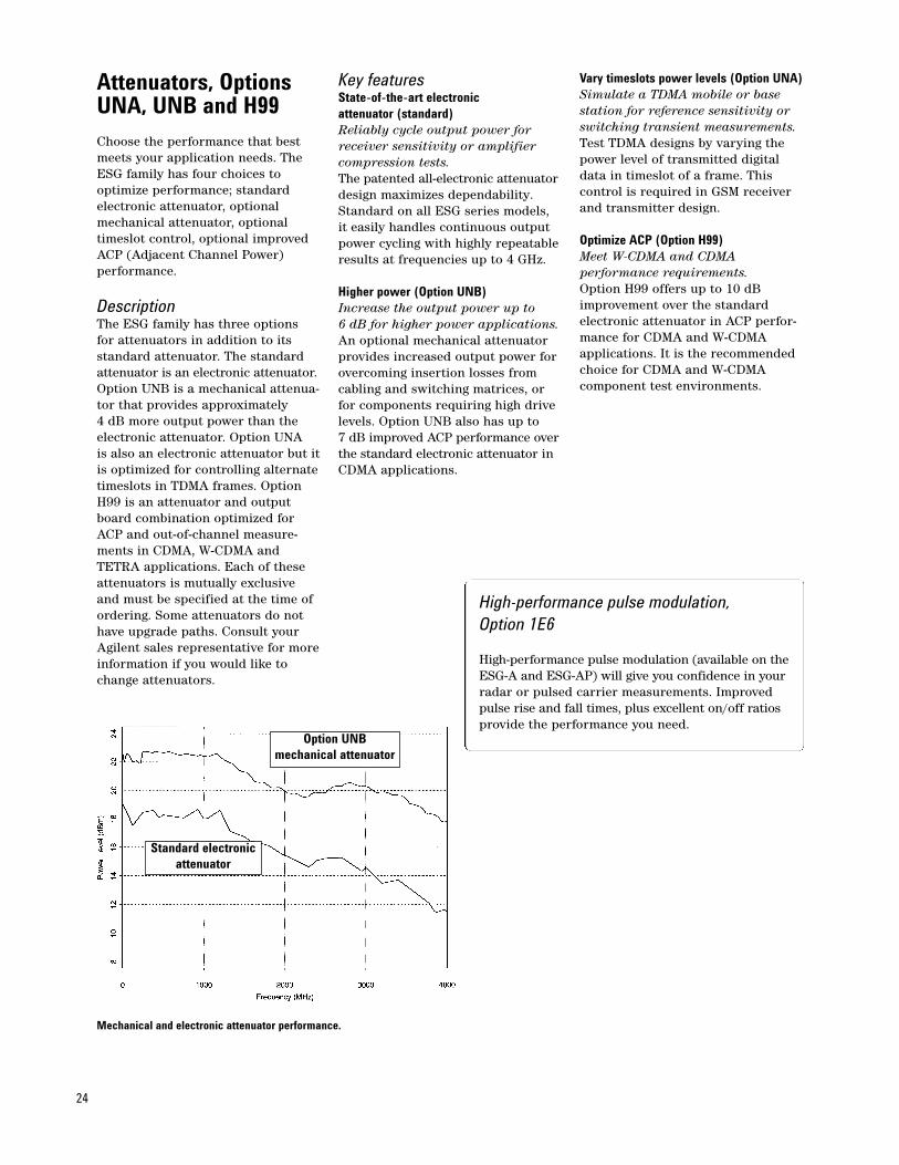
DescriptionThe ESG family has three options for attenuators in addition to itsstandard attenuator. The standardattenuator is an electronic attenuator.Option UNB is a mechanical attenua-tor that provides approximately 4 dB more output power than theelectronic attenuator. Option UNA is also an electronic attenuator but itis optimized for controlling alternatetimeslots in TDMA frames. OptionH99 is an attenuator and outputboard combination optimized forACP and out-of-channel measure-ments in CDMA, W-CDMA andTETRA applications. Each of theseattenuators is mutually exclusiveand must be specified at the time ofordering. Some attenuators do nothave upgrade paths. Consult yourAgilent sales representative for moreinformation if you would like tochange attenuators.
Key featuresState-of-the-art electronic attenuator (standard)Reliably cycle output power for receiver sensitivity or amplifier compression tests.The patented all-electronic attenuatordesign maximizes dependability.Standard on all ESG series models,it easily handles continuous outputpower cycling with highly repeatableresults at frequencies up to 4 GHz.
Higher power (Option UNB)Increase the output power up to 6 dB for higher power applications.An optional mechanical attenuator provides increased output power forovercoming insertion losses fromcabling and switching matrices, or for components requiring high drivelevels. Option UNB also has up to 7 dB improved ACP performance overthe standard electronic attenuator inCDMA applications.
Vary timeslots power levels (Option UNA)Simulate a TDMA mobile or base station for reference sensitivity orswitching transient measurements.Test TDMA designs by varying thepower level of transmitted digitaldata in timeslot of a frame. This control is required in GSM receiverand transmitter design.
Optimize ACP (Option H99)Meet W-CDMA and CDMA performance requirements.Option H99 offers up to 10 dBimprovement over the standard electronic attenuator in ACP perfor-mance for CDMA and W-CDMAapplications. It is the recommendedchoice for CDMA and W-CDMA component test environments.
Mechanical and electronic attenuator performance.
Option UNBmechanical attenuator
Standard electronicattenuator
High-performance pulse modulation,Option 1E6
High-performance pulse modulation (available on theESG-A and ESG-AP) will give you confidence in yourradar or pulsed carrier measurements. Improved pulse rise and fall times, plus excellent on/off ratiosprovide the performance you need.
25
Documentation, support and mechanical hardware options (available with any ESG model)
Mechanical options Option 1CM Rack mount kit Option 1CN Handle kit Option 1EM Moves all connectors to the rear panel Option 1CP Rack mount and handle
Operating and service documentation options Option 0B0 Deletes manual set Option 0B1 Adds manual set Option 0BV Service documentation (component level) Option 0BW Service documentation (assembly level) Option 0BX Service documentation (assembly and component level) Option UK6 Commercial calibration certificate with test data
Service options Option W32 3 years of customer return calibration service Option W34 3 years of customer return compliant calibration
(ANSI 540 standard) service Option W50 Adds additional warranty for a total of 5 years of
customer return repair service Option W52 5 years of customer return calibration service Option W54 5 years of customer return compliant calibration
(ANSI 540 standard) service
Localization options Options ABO Chinese (Taiwan) manuals Options ABD German manuals Options AB1 Korean manuals Options ABE Spanish manuals Options AB2 Chinese manuals Options ABF French manuals Options ABJ Japanese manuals
Accessories 9211-1296 Transit case 83300A Remote interface
26
Agilent application and product information
• RF Source Basics, a self-based tutorial (CD ROM), literature number 5980-2060E.
• Digital Modulation in Communications Systems—An Introduction, Application Note 1298, literature number 5965-7160E.
• Generating and Downloading Data to the ESG-D RF Signal Generator for Digital Modulation, Product Note, literature number 5966-1010E.
• Using Vector Modulation Analysis in the Integration, Troubleshooting and Design of Digital RF Communications Systems, Product Note 89400-8, literature number 5091-8687E.
• Controlling TDMA Timeslot Power Levels Using the ESG-D Series, RF Signal Generators, Product Note, literature number 5966-4472E.
• Testing CDMA Base Station Amplifiers, Application Note 1307, literature number 5967-5486E.• Customize Digital Modulation with the ESG-D Series Real-Time I/Q Baseband Generator, Option UN8,
Product Note, literature number 5966-4096E.• Using the ESG-D RF Signal Generator’s Multicarrier, Multichannel CDMA Personality
for Component Test, Option UN5, Product Note, literature number 5968-2981E.• Generating Digital Modulation with the ESG-D Series Dual Arbitrary Waveform Generator, Option UND,
Product Note, literature number 5966-4097E.• Understanding GSM Transmitter Measurements for Base Transceiver Stations and Their Components,
Application Note 1312, literature number 5968-2320E.• Understanding CDMA Measurements for Base Stations and their Components, Application Note 1311,
literature number 5968-0953E.• Testing and Troubleshooting Digital RF Communications Receiver Designs, Application Note 1314,
literature number 5968-3579E.• Performing Bluetooth RF Measurements Today, Application Note 1333, literature number 5968-7746E.• Designing and Testing 3GPP W-CDMA Base Stations, Application Note 1355, literature number 5980-1239E.• Designing and Testing 3GPP W-CDMA User Equipment, Application Note 1356, literature number 5980-1238E.• Designing and Testing cdma2000 Base Stations, Application Note 1357, literature number 5980-1303E.• Designing and Testing cdma2000 Mobile Stations, Application Note 1358, literature number 5980-1237E.• ESG Series RF Signal Generators Option 200 W-CDMA, Product Overview, literature number 5988-0369EN.• ESG Series RF Signal Generators Option 201 cdma2000, Product Overview, literature number 5988-0371EN.• Using the ESG-D Series of RF Signal Generators and the 8922 GSM Test Set for GSM Applications, Product Note,
literature number 5965-7158E
Product literature• ESG Family RF Digital and Analog Signal Generators, Brochure, literature number 5968-4313E.• ESG Family RF Signal Generators, Data Sheet, literature number 5965-3096E.• ESG Family RF Signal Generators, Configuration Guide, literature number 5965-4973E.• RF and Microwave Signal Generators, Catalog, literature number 5965-3094E.• IntuiLink Software, Data Sheet, literature number 5980-3115EN.
See the ESG Web pageGet the latest news, product and support information, application literature and more. The Agilent TechnologiesInternet address for the ESG family is: http://www.agilent.com/find/esg
New trade-up programAsk your local sales representative about instrument trade-up opportunities for all ESG models.
IntuiLink PC softwareTransfer screen data and images easily into Microsoft® Excel and Microsoft® Word. Save and restore instrumentstates. Download arbitrary waveform files. For more information visit our website at:http//www.agilent.com/find/IntuiLink

27
For further information
Related literature:Agilent ESG Family of RF SignalGenerators, Data Sheet,literature number 5965-3096E
IntuiLink Software, Data Sheet,literature number 5980-3115EN
Agilent Technologies’ Test and MeasurementSupport, Services, and AssistanceAgilent Technologies aims to maximize thevalue you receive, while minimizing your riskand problems. We strive to ensure that you get the test and measurement capabilities youpaid for and obtain the support you need. Ourextensive support resources and services canhelp you choose the right Agilent products foryour applications and apply them successfully.Every instrument and system we sell has aglobal warranty. Support is available for at least five years beyond the production life ofthe product. Two concepts underlie Agilent’s overall support policy: “Our Promise” and “Your Advantage.”
Our PromiseOur Promise means your Agilent test and measurement equipment will meet its advertised performance and functionality. When you are choosing new equipment, we will help you with product information,including realistic performance specificationsand practical recommendations from experienced test engineers. When you useAgilent equipment, we can verify that it worksproperly, help with product operation, and provide basic measurement assistance for the use of specified capabilities, at no extracost upon request. Many self-help tools areavailable.
Your AdvantageYour Advantage means that Agilent offers a wide range of additional expert test and measurement services, which you can purchaseaccording to your unique technical and business needs. Solve problems efficiently and gain a competitive edge by contracting with us for calibration, extra-cost upgrades,out-of-warranty repairs, and on-site educationand training, as well as design, system integration, project management, and other professional engineering services. ExperiencedAgilent engineers and technicians worldwidecan help you maximize your productivity, optimize the return on investment of yourAgilent instruments and systems, and obtaindependable measurement accuracy for the life of those products.
By internet, phone, or fax, get assistance withall your test & measurement needs
Online assistance:
www.agilent.com/find/assist
Phone or Fax:
United States:(tel) 1 800 452 4844
Canada:(tel) 1 877 894 4414(fax) (905) 282-6495
China:(tel) 800 810 0189(fax) 1 0800 650 0121
Europe:(tel) (31 20) 547 2323(fax) (31 20) 547 2390
Japan:(tel) (81) 426 56 7832(fax) (81) 426 56 7840
Korea:(tel) (82 2) 2004-5004(fax) (82 2) 2004-5115
Latin America:(tel) (305) 269 7500(fax) (305) 269 7599
Taiwan:(tel) 080 004 7866(fax) (886 2) 2545 6723
Other Asia Pacific Countries:(tel) (65) 375 8100(fax) (65) 836 0252Email: [email protected]
Product specifications and descriptions in thisdocument subject to change without notice.
Copyright © 2001 Agilent Technologies, Inc.Printed in USA, June 11, 20015965-4973E
Microsoft®Excel and Microsoft® Word are U.S. registered trademarks of Microsoft Corporation
MATLAB™ is a U.S. registered trademark of The Mathworks, Inc.