agilent e7515a uxm wireless test set -...
TRANSCRIPT

Agilent E7515A UXM
Wireless Test Set
Programmer’s Reference
ii
Notices
© Agilent Technologies, Inc. 2014
No part of this manual may be reproduced in
any form or by any means (including electronic
storage and retrieval or translation into a
foreign language) without prior agreement and
written consent from Agilent Technologies, Inc.
as governed by United States and international
copyright laws.
Warranty
The material contained in this document is
provided “as is,” and is subject to being
changed, without notice, in future editions.
Further, to the maximum extent permitted by
applicable law, Agilent disclaims all
warranties, either express or implied, with
regard to this manual and any information
contained herein, including but not limited to
the implied warranties of merchantability
and fitness for a particular purpose. Agilent
shall not be liable for errors or for incidental
or consequential damages in connection with
the furnishing, use, or performance of this
document or of any information contained
herein. Should Agilent and the user have a
separate written agreement with warranty
terms covering the material in this document
that conflict with these terms, the warranty
terms in the separate agreement shall
control.
Statement of Compliance
This product has been designed and tested in
accordance with accepted industry standards,
and has been supplied in a safe condition.
The documentation contains information and
warnings that must be followed by the user to
ensure safe operation and to maintain the
product in a safe condition.
Manual Part Number
E7515-90001
Edition
June 19th, 2014
Documents Software Version 1.1.1.0
Documents Platform Version 1.1.1.0
Agilent Technologies, Inc.
Technology Licenses
The hardware and/or software described in
this document are furnished under a license
and may be used or copied only in accordance
with the terms of such license.
Restricted Rights Legend
If software is for use in the performance of a
U.S. Government prime contract or
subcontract, Software is delivered and
licensed as “Commercial computer software”
as defined in DFAR 252.227-7014 (June 1995),
or as a “commercial item” as defined in FAR
2.101(a) or as “Restricted computer software”
as defined in FAR 52.227-19 (June 1987) or
any equivalent agency regulation or contract
clause. Use, duplication or disclosure of
Software is subject to Agilent Technologies’
standard commercial license terms, and non-
DOD Departments and Agencies of the U.S.
Government will receive no greater than
Restricted Rights as defined in FAR 52.227-
19(c)(1-2) (June 1987). U.S. Government users
will receive no greater than Limited Rights as
defined in FAR 52.227-14 (June 1987) or DFAR
252.227-7015 (b)(2) (November 1995), as
applicable in any technical data.
Safety Notices
The following general safety precautions must
be observed during all phases of operation of
this instrument. Failure to comply with these
precautions or with specific warnings
elsewhere in this manual violates safety
standards of design, manufacture, and
intended use of the instrument. Agilent
Technologies Inc. assumes no liability for the
customer’s failure to comply with these
requirements.
A CAUTION notice denotes a hazard.
It calls attention to an operating
procedure, practice, or the like that,
if not correctly performed or
adhered to, could result in damage
to the product or loss of important
data. Do not proceed beyond a
CAUTION notice until the indicated
conditions are fully understood and
met.
A WARNING notice denotes a
hazard. It calls attention to an
operating procedure, practice, or
the like that, if not correctly
performed or adhered to, could
result in personal injury or death.
Do not proceed beyond a WARNING
notice until the indicated conditions
are fully understood and met.
Electrical Rating
Input Voltage Range: 100/120/220/240 VAC
Input Frequency Range: 50/60Hz, nominal
Input Power Rating: 1100 Watts Max
Mains supply voltage fluctuates up
to
+/- 10% of the nominal voltage.
CAUTION
WARNING
iii
Where to Find the Latest Information
Agilent will periodically update product documentation. For the latest information about this wireless test
set, including software upgrades, operating and application information, and product and accessory
information, see the following URL: www.agilent.com/find/UXM
Is your product software up-to-date?
Agilent will periodically release software updates to fix known defects and incorporate product
enhancements. To search for software updates for your product, go to the Agilent Technical Support
website at
www.agilent.com/find/softwaremanager

iv
This page is intentionally left blank.
v
Table of Contents
1 Introduction .......................................................................................................................................... 11
About the LTE/LTE-A Test/Lab Application ......................................................................................................... 11
Objective of this Document ...................................................................................................................................... 11
Latest documentation ................................................................................................................................................ 11
2 General conventions ............................................................................................................................ 12
3 Communication with the instrument ................................................................................................. 13
4 Common commands ............................................................................................................................ 14
*OPC .............................................................................................................................................................................. 14
*RST .............................................................................................................................................................................. 14
*IDN? ............................................................................................................................................................................ 15
SYSTem:VERSion? ...................................................................................................................................................... 15
5 “CELL” configuration commands ...................................................................................................... 17
SETup:LTE:DUPLEXmode .......................................................................................................................................... 17
SETup<carrier_id#>:LTE:DLEARFcn ....................................................................................................................... 17
SETup:LTE:ULEARFcn ................................................................................................................................................ 19
SETup<carrier_id#>:LTE:DLBANDWidth ............................................................................................................... 21
SETup:LTE:ULBANDWidth ........................................................................................................................................ 22
SETup<carrier_id#>:LTE:CPSIZe ............................................................................................................................. 23
SETup<carrier_id#>:LTE:CELLID ............................................................................................................................. 23
SETup<carrier_id#>:LTE:POWLVL .......................................................................................................................... 24
SETup<carrier_id#>:LTE: TOTALPOWLVL ............................................................................................................ 25
SETup<carrier_id#>:LTE:SIMPATHLOSS .............................................................................................................. 25
SETup<carrier_id#>:LTE:MCC ................................................................................................................................. 26
SETup<carrier_id#>:LTE:MNC ................................................................................................................................ 26
SETup:LTE:FRAMECFG .............................................................................................................................................. 27
SETup:LTE:SPCSUBFRAMECFG ............................................................................................................................... 28
6 “Rel10” configuration commands ..................................................................................................... 30
SETup:LTE:CARRIERAGGREGATION:STATE .......................................................................................................... 30
SETup:LTE:SCCTIMINGdifference ........................................................................................................................... 30
SETup<carrier_id#>:LTE:CSIREFSIGNalsconfiguration:STATe.......................................................................... 31
SETup<carrier_id#>:LTE:CSIREFSIGNalsconfiguration:ANTENNAPORTS ...................................................... 31
SETup<carrier_id#>:LTE:CSIREFSIGNalsconfiguration:RESOURCECFG .......................................................... 32
SETup<carrier_id#>:LTE: CSIREFSIGNalsconfiguration:SUBFRAMECFG ........................................................ 33
SETup<carrier_id#>:LTE:CSIREFSIGNalsconfiguration:PC................................................................................. 33
SETup<carrier_id#>:LTE:CSIREFSIGNalsconfiguration:ZEROPOWer:RESOURCECFG ................................... 34
SETup<carrier_id#>:LTE:CSIREFSIGNalsconfiguration:ZEROPOWer:SUBFRAMECFG ................................. 35

vi
7 “RMC” configuration commands ...................................................................................................... 36
SETup<carrier_id#>:LTE:RMC:DL:TXMODe .......................................................................................................... 36
SETup<carrier_id#>:LTE:RMC:DL:IMCS[:ALL] ...................................................................................................... 37
SETup<carrier_id#>:LTE:RMC:DL:IMCS:SFN<sub_frame#>:[ALLCW] ........................................................... 38
SETup<carrier_id#>:LTE:RMC:DL:IMCS:SFN<sub_frame#>:CW<codeword#> ........................................... 40
SETup<carrier_id#>:LTE:RMC:DL:FRAMEREPetitionperiod ............................................................................... 42
SETup<carrier_id#>:LTE:RMC:DL:ALLOCSIZe[:ALL] ........................................................................................... 42
SETup<carrier_id#>:LTE:RMC:DL:ALLOCSIZe:SFN<sub_frame#> .................................................................. 43
SETup<carrier_id#>:LTE:RMC:DL:ALLOCOFFset[:ALL] ....................................................................................... 44
SETup<carrier_id #>:LTE:RMC:DL:ALLOCOFFset:SFN<sub_frame#>............................................................. 45
SETup<carrier_id#>:LTE:RMC:DL:ALLOCBITMAP[:ALL] .................................................................................... 46
SETup<carrier_id#>:LTE:RMC:DL:ALLOCBITMAP:SFN<sub_frame#> ........................................................... 46
SETup:LTE:RMC:UL:IMCS[:ALL] ............................................................................................................................... 47
SETup:LTE:RMC:UL:IMCS:SFN<sub_frame#> ...................................................................................................... 49
SETup:LTE:RMC:UL:FRAMEREPetitionperiod ........................................................................................................ 51
SETup:LTE:RMC:UL:ALLOCSIZe[:ALL] .................................................................................................................... 51
SETup:LTE:RMC:UL:ALLOCSIZe:SFN<sub_frame#> ........................................................................................... 52
SETup:LTE:RMC:UL:ALLOCOFFset[:ALL] ................................................................................................................ 53
SETup:LTE:RMC:UL:ALLOCOFFset:SFN<sub_frame#> ....................................................................................... 53
SETup:LTE:RMC:UL:CSI[:ALL] ................................................................................................................................... 54
SETup:LTE:RMC:UL:CSI:SFN<sub_frame#> ......................................................................................................... 54
SETup:LTE:RMC:CROSSCHEDuling ......................................................................................................................... 55
SETup<carrier_id#>:LTE:RMC:CQISCHEDuling:STATe ....................................................................................... 56
SETup<carrier_id#>:LTE:RMC:CQISCHEDuling:PRECODINGMODE ................................................................. 56
SETup<carrier_id#>:LTE:RMC:CQISCHEDuling:IMCSCQI<cqi_value#> ......................................................... 57
8 “HARQ” configuration commands..................................................................................................... 60
SETup <carrier_id #>:LTE:HARQ:DL:MAXRETRANSmissions ........................................................................... 60
SETup<carrier_id#>:LTE:HARQ:DL:REDUNDancyversionlist ............................................................................. 60
SETup:LTE:HARQ:UL:MAXRETRANSmissions ...................................................................................................... 61
SETup:LTE:HARQ:REPORTingmode ......................................................................................................................... 61
9 “Boosting” configuration commands ............................................................................................... 63
SETup<carrier_id #>:LTE: BOOSTing:PDSCH:PA ................................................................................................. 63
SETup<carrier_id #>:LTE: BOOSTing:PDSCH:PB ................................................................................................. 63
SETup<carrier_id #>:LTE: BOOSTing:PSS:PA ...................................................................................................... 64
SETup<carrier_id #>:LTE: BOOSTing:SSS:PA ...................................................................................................... 65
SETup<carrier_id #>:LTE: BOOSTing:OTHER:PA ................................................................................................. 66
SETup<carrier_id #>:LTE: BOOSTing:OTHER:PB ................................................................................................. 67
10 “Measurements” configuration commands ..................................................................................... 69
SETup <carrier_id #>:LTE:MEASREP:CQIPMIRI[:ENABLE] ............................................................................... 69
vii
SETup <carrier_id #>:LTE:MEASREP:CQIPMIRI:MODE ...................................................................................... 69
SETup<carrier_id#>:LTE:MEASREP:CQIPMIRI:CQIPMICFGIDX ........................................................................ 70
SETup <carrier id #>:LTE:MEASREP:CQIPMIRI:RICFGIDX ................................................................................. 71
SETup :LTE:MEASREP:APERIODic[:ENABLE]........................................................................................................ 71
SETup :LTE:MEASREP:APERIODic:MODE .............................................................................................................. 72
SETup:LTE:MEASREP:RSRPRSRQ[:ENABLE] ........................................................................................................ 73
SETup:LTE:MEASREP:RSRPRSRQ:PERIODicity ..................................................................................................... 74
SETup:LTE:MEASREP:RSRPRSRQ:RSRPFILTERing ............................................................................................... 75
SETup:LTE:MEASREP:RSRPRSRQ:RSRQFILTERing .............................................................................................. 76
11 “L1 Advanced” configuration commands ......................................................................................... 78
SETup <carrier_id #>:LTE:CNTRLREGionconfiguration:CFI ............................................................................... 78
SETup<carrier_id#>:LTE:CNTRLREGionconfiguration:AGGRegationlevel:COMMonsearchspace .............. 78
SETup<carrier_id#>:LTE:CNTRLREGionconfiguration:AGGRegationlevel:UEspecificsearchspace ............. 79
SETup <carrier_id#>:LTE:PHICHconfiguration:DURation ................................................................................... 79
SETup<carrier_id#>:LTE:PHICHconfiguration:RESources .................................................................................. 80
SETup:LTE:PRACHconfiguration:CFGIDX ............................................................................................................... 81
SETup:LTE:PRACHconfiguration:ROOTSEQIDX ..................................................................................................... 81
SETup:LTE:PRACHconfiguration:FREQOFFset ....................................................................................................... 82
SETup:LTE:REFSIGNalsconfiguration:GRPHOPPingenable ................................................................................. 83
SETup:LTE:REFSIGNalsconfiguration:SEQHOPPingenable.................................................................................. 83
SETup:LTE:REFSIGNalsconfiguration:CYCLICSHIFT ............................................................................................. 84
12 “L2 Advanced” configuration commands ......................................................................................... 85
SETup:LTE:RACHconfiguration:NUMPREAMbles ................................................................................................. 85
SETup:LTE:RACHconfiguration:INITRXPWRLEVel ................................................................................................ 85
SETup:LTE:RACHconfiguration:PWRRAMPSTEP .................................................................................................. 86
SETup:LTE:RACHconfiguration:MAXPREAMBLETXATTEMPTS ........................................................................ 87
SETup:LTE:RACHconfiguration:RESPWINDOWSIZe ............................................................................................ 87
SETup:LTE:RACHconfiguration:CONTENTIONRESOLTIMer................................................................................ 88
SETup:LTE:RACHconfiguration:MSG3MAXHARQRETRANSmission ................................................................. 89
SETup:LTE:SRconfiguration:VALue ......................................................................................................................... 89
SETup:LTE:SRconfiguration:PUCCHRESIDX ........................................................................................................... 90
SETup:LTE:SRconfiguration:CFGIDX ........................................................................................................................ 90
SETup:LTE:SRconfiguration:DSRTXMAX ................................................................................................................ 91
SETup:LTE:CRNTI ....................................................................................................................................................... 92
13 “RRC/NAS” configuration commands ............................................................................................. 93
SETup:LTE:TIMERconfiguration:T300 ..................................................................................................................... 93
SETup:LTE:TIMERconfiguration:T301 ..................................................................................................................... 93
SETup:LTE:TIMERconfiguration:T310 ..................................................................................................................... 94
SETup:LTE:TIMERconfiguration:T311 ..................................................................................................................... 95
viii
SETup:LTE:CONSTANTconfiguration:N310 ............................................................................................................ 95
SETup:LTE:CONSTANTconfiguration:N311 ............................................................................................................ 96
SETup:LTE:IP:APN ...................................................................................................................................................... 97
SETup:LTE:IP:V4ADDRess ......................................................................................................................................... 97
SETup:LTE:SIGNALINGMODE .................................................................................................................................. 98
SETup:LTE:RLF ............................................................................................................................................................ 99
14 “Security” configuration commands .............................................................................................. 100
SETup:LTE:SECURITYconfiguration:STATe .......................................................................................................... 100
SETup:LTE:SECURITYconfiguration:AUTHKey ..................................................................................................... 100
SETup:LTE:SECURITYconfiguration:INTEGrity ..................................................................................................... 101
SETup:LTE:SECURITYconfiguration:CIPHering .................................................................................................... 102
15 “DRB” configuration commands ..................................................................................................... 103
SETup:LTE:DRB:RLCMode ...................................................................................................................................... 103
SETup:LTE:DRB:ID .................................................................................................................................................... 103
SETup:LTE:DRB:UM:TREordering........................................................................................................................... 104
SETup:LTE:DRB:AM:TREordering .......................................................................................................................... 104
SETup:LTE:DRB:AM: TSPRohibit ........................................................................................................................... 105
SETup:LTE:DRB:AM: TPRetransmit ....................................................................................................................... 106
SETup:LTE:DRB:AM: PPDU ..................................................................................................................................... 107
SETup:LTE:DRB:AM: PBYTe ................................................................................................................................... 107
SETup: LTE:DRB:AM: MRTHreshold ..................................................................................................................... 108
16 “SYSTEM” configuration commands .............................................................................................. 110
SETup <carrier_id#>:SYSTem:RFCONNection:DUPlex ..................................................................................... 110
SETup<carrier_id#>:SYSTem:RFCONNection:CORRections:TX1:FREQuency ............................................... 110
SETup<carrier_id#>:SYSTem:RFCONNection:CORRections:TX1:AMPOFFset .............................................. 111
SETup<carrier_id#>:SYSTem:RFCONNection:CORRections:TX1:STATe ....................................................... 112
SETup<carrier_id#>:SYSTem:RFCONNection:CORRections:TX2:FREQuency ............................................... 113
SETup<carrier_id#>:SYSTem:RFCONNection:CORRections:TX2:AMPOFFset .............................................. 113
SETup<carrier_id#>:SYSTem:RFCONNection:CORRections:TX2:STATe ....................................................... 114
SETup<carrier_id#>:SYSTem:RFCONNection:CORRections:TXRX:FREQuency ............................................ 115
SETup<carrier_id#>:SYSTem:RFCONNection:CORRections:TXRX:AMPOFFset ........................................... 115
SETup<carrier_id#>:SYSTem:RFCONNection:CORRections:TXRX:STATe .................................................... 116
SETup<carrier_id#>:LTE:MULTANTennaconfiguration .................................................................................... 117
17 “CHANNEL IMPAIRMENTS” configuration commands ............................................................... 118
SETup<carrier_id#>:LTE:IMPAIRments:AWGN:STATe .................................................................................... 118
SETup<carrier_id #>:LTE:IMPAIRments:AWGN:POWLVL ............................................................................... 118
SETup<carrier_id#>:LTE:IMPAIRments:FADER:STATe .................................................................................... 119
SETup<carrier_id#>:LTE:IMPAIRments:FADER:CORRELATIONmode............................................................ 120
SETup<carrier_id#>: LTE:IMPAIRments:OCNG:STATe .................................................................................... 121

ix
18 “POWER CONTROL” configuration commands ............................................................................. 122
CNTRL:LTE:CONNECTion:UL:ULPOWer ................................................................................................................ 122
CNTRL:LTE:CONNECTion:UL:TPCCTRL ................................................................................................................. 122
19 OPERATION COMMANDS ................................................................................................................. 124
CNTRL:LTE:BCAST:STATe ...................................................................................................................................... 124
CNTRL:LTE:ATTACH:STATe.................................................................................................................................... 124
CNTRL:LTE:CONNECTion:DL:STATe ..................................................................................................................... 125
CNTRL:LTE:CONNECTion:UL:STATe ..................................................................................................................... 126
CNTRL:LTE:ACTIVATESCC:STATe ......................................................................................................................... 127
SETup:LTE:RMC:BlindHandOver ............................................................................................................................ 127
SETup :LTE:RMC:SCCRECONFiguration ................................................................................................................ 128
20 TX MEASUREMENTS commands ..................................................................................................... 130
READ:LTE:MEASure:CONSTellation:EVMagnitude? ........................................................................................... 130
READ:LTE:MEASure:FRQERRor? ............................................................................................................................ 131
READ:LTE:MEASure:CONSTellation:IQOFFset? ................................................................................................... 131
READ:LTE:MEASure:CONSTellation:EVMVSSYMBol? ....................................................................................... 132
READ:LTE:MEASure:CONSTellation:EVMVSCARRier? ...................................................................................... 133
SETup:LTE:MEASure:OBW ..................................................................................................................................... 133
READ:LTE:MEASure:OBW?..................................................................................................................................... 134
READ:LTE:MEASure:SFLatness? ............................................................................................................................ 135
READ:LTE:MEASure:CHPOWer? ............................................................................................................................ 135
READ:LTE:MEASure:PAPR? .................................................................................................................................... 136
21 RX MEASUREMENTS commands .................................................................................................... 137
SETup:LTE:MEASure:RCVRBLER:MEASLENgth .................................................................................................. 137
READ<carrier:_id#>:LTE:MEASure:RCVRBLER? ................................................................................................ 137
READ:LTE:MEASure:TOTALRCVRBLER? .............................................................................................................. 138
READ:LTE:MEASure:COMPACT:RCVRBLER? ...................................................................................................... 138
READ:LTE:MEASure:TXBLER? ................................................................................................................................ 139
SETup:LTE:MEASure:CQIREPorting:MEASLENgth ............................................................................................. 140
READ<carrier_id#>:LTE:MEASure:CQIREPorting? ............................................................................................. 140
READ:LTE:MEASure:RSRPRSRQREPorting? ........................................................................................................ 141
READ:LTE:MEASure: DL:IPTHroughput? .............................................................................................................. 142
READ:LTE:MEASure: UL:IPTHroughput? .............................................................................................................. 142
READ:LTE:MEASure: COMPact:IPTHroughput? .................................................................................................. 143
READ<carrier_id#>:LTE:MEASure:HISTogram:CQI? ......................................................................................... 144
READ<carrier_id#>:LTE:MEASure:HISTogram:RI? ............................................................................................ 145
22 Troubleshooting .................................................................................................................................. 146
Returning Your Test Set for Service ...................................................................................................................... 146

x
This page is intentionally left blank.
Agilent UXM Wireless Test Set
Programmer’s Reference
11
1 Introduction
Welcome to the Programmer’s Reference for the Agilent E7515A UXM Wireless Test Set (UXM). The
purpose of this guide is to provide you with all that is required to configure the UXM for remote control as
well as the commands needed to operate it. Each command includes a description, range, preset value,
return parameters list, and an example of the command used successfully. For additional information,
please refer to the UXM Getting Started Guide and User’s Guide for this instrument.
About the LTE/LTE-A Test/Lab Application
Agilent E7530A/E7630A LTE/LTE-A Test/Lab Application (TA/LA) enables LTE and LTE-Advanced user
equipment (UE) design validation.
The application runs on an embedded Windows controller present in the UXM and uses the provided
touch-screen based interface, integrated fading, network emulation and measurement capabilities present in
the test set to provide you with a simple to use, bench-top design verification tool.
The software application provides two different operation modes:
Signaling based mode: In this operation mode, the TA/LA is capable of emulating a single cell LTE
and LTE-Advanced network (or dual cell network if you purchased the E7515A-RB1/BB1 as well as
the -RA1/BA1). This operation mode enables you to recreate test environments similar to the real-
life conditions the UE will encounter during its operation on an actual network including fading and
MIMO variations.
In the signaling operation mode, you are also capable of configuring several communication
parameters, ranging from the different modulation and coding schemes, to the size of the
bandwidth allocations for both UL and DL, as well as other additional parameters.
If you have purchased the option -AFP for your TA or FDD version A.02 of the LA , then, you can
also configure the DL Carrier Components (CC) and other related Carrier Aggregation requirements.
For more information on Carrier Aggregation, visit the 3GPP website’s description.
Non-signaling based mode: In this operation mode, you can configure the test set to generate a
compliant broadcast signal, and start the transmission of PDCCH channel with allocations for the
UE, without the need to complete an ATTACH procedure with the UXM.
Objective of this Document
This document describes the SCPI command set implemented in the TA/LA to enable you to control it
remotely from external software applications.
This document should be used together with the Agilent E7515A UXM Getting Started Guide and the
Agilent E7515A UXM User’s Guide.
Latest documentation
For the latest documentation and software updates for the above products, please go to
www.agilent.com/find/uxm.

Agilent UXM Wireless Test Set
Programmer’s Reference
12
2 General conventions
The TA/LA SCPI implementation only allows the execution of sequential commands. Overlapped SCPI
command operation is not supported.
All commands which state return parameters accept the query format.
During normal operation, if you wish to check the correct application of command configuration issued, you
can issue the same command in query form to verify successful execution. For some commands, it is
recommended to check the “operation complete” status (*OPC?) in order to confirm the execution has been
completed before sending the next command.
The TA/LA enters remote-control mode once it detects SCPI commands are being sent to its control interface.
The graphical user-interface (GUI) indicates this by displaying a dialogue box that enables you to cancel the
remote-control mode. You cannot execute any actions via the GUI while the UXM is being controlled remotely.
The dialogue box enables you to cancel the remote connection at any time.
Agilent UXM Wireless Test Set
Programmer’s Reference
13
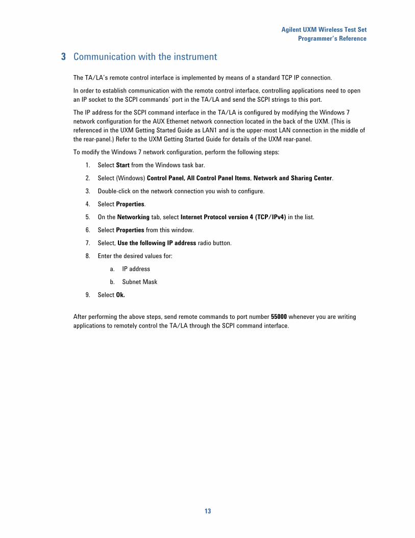
3 Communication with the instrument
The TA/LA’s remote control interface is implemented by means of a standard TCP IP connection.
In order to establish communication with the remote control interface, controlling applications need to open
an IP socket to the SCPI commands’ port in the TA/LA and send the SCPI strings to this port.
The IP address for the SCPI command interface in the TA/LA is configured by modifying the Windows 7
network configuration for the AUX Ethernet network connection located in the back of the UXM. (This is
referenced in the UXM Getting Started Guide as LAN1 and is the upper-most LAN connection in the middle of
the rear-panel.) Refer to the UXM Getting Started Guide for details of the UXM rear-panel.
To modify the Windows 7 network configuration, perform the following steps:
1. Select Start from the Windows task bar.
2. Select (Windows) Control Panel, All Control Panel Items, Network and Sharing Center.
3. Double-click on the network connection you wish to configure.
4. Select Properties.
5. On the Networking tab, select Internet Protocol version 4 (TCP/IPv4) in the list.
6. Select Properties from this window.
7. Select, Use the following IP address radio button.
8. Enter the desired values for:
a. IP address
b. Subnet Mask
9. Select Ok.
After performing the above steps, send remote commands to port number 55000 whenever you are writing
applications to remotely control the TA/LA through the SCPI command interface.

Agilent UXM Wireless Test Set
Programmer’s Reference
14
4 Common commands
*OPC
Function
This command sets the “Operation Complete” bit in the Standard Event Status Register, since the TA/LA
does not support overlapped command operation.
If executed in query form, this command places “1” in the output queue.
Allowed range when setting the parameter value
None, this command does not accept input parameters.
Returned range when querying the parameter value
This command places a “1” in the output queue.
Preset parameter value
Not applicable
Programming example
Command form
Not applicable
Query form
*OPC?
*RST
Function
This command forces a preset in the TA/LA.
All configuration parameters revert to their default values.
Constraints
This setting can only be changed when the instrument is in the CELL OFF state.
Allowed range when setting the parameter value
None, this command does not accept input parameters.
Returned range when querying the parameter value
None, this command does not support query format.
Preset parameter value
Not applicable
Agilent UXM Wireless Test Set
Programmer’s Reference
15
Programming example
Command form
*RST
Query form
Not applicable
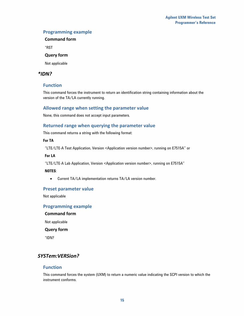
*IDN?
Function
This command forces the instrument to return an identification string containing information about the
version of the TA/LA currently running.
Allowed range when setting the parameter value
None, this command does not accept input parameters.
Returned range when querying the parameter value
This command returns a string with the following format:
For TA
“LTE/LTE-A Test Application, Version <Application version number>, running on E7515A” or
For LA
“LTE/LTE-A Lab Application, Version <Application version number>, running on E7515A”
NOTES:
Current TA/LA implementation returns TA/LA version number.
Preset parameter value
Not applicable
Programming example
Command form
Not applicable
Query form
*IDN?
SYSTem:VERSion?
Function
This command forces the system (UXM) to return a numeric value indicating the SCPI version to which the
instrument conforms.
Agilent UXM Wireless Test Set
Programmer’s Reference
16
Allowed range when setting the parameter value
None, this command does not accept input parameters.
Returned range when querying the parameter value
This command returns a string with the following format:
YYYY.V
Where YYYY indicates the year version of the SCPI standard implemented, and V indicates the implemented
approved revision.
Preset parameter value
Not applicable
Programming example
Command form
Not applicable
Query form
*SYST:VERS?
Agilent UXM Wireless Test Set
Programmer’s Reference
17
5 “CELL” configuration commands
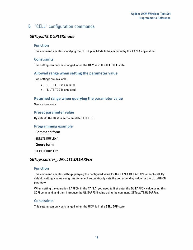
SETup:LTE:DUPLEXmode
Function
This command enables specifying the LTE Duplex Mode to be emulated by the TA/LA application.
Constraints
This setting can only be changed when the UXM is in the CELL OFF state.
Allowed range when setting the parameter value
Two settings are available:
0, LTE FDD is emulated.
1, LTE TDD is emulated.
Returned range when querying the parameter value
Same as previous.
Preset parameter value
By default, the UXM is set to emulated LTE FDD.
Programming example
Command form
SET:LTE:DUPLEX 1
Query form
SET:LTE:DUPLEX?
SETup<carrier_id#>:LTE:DLEARFcn
Function
This command enables setting/querying the configured value for the TA/LA DL EARFCN for each cell. By
default, setting a value using this command automatically sets the corresponding value for the UL EARFCN
parameter.
When setting the operation EARFCN in the TA/LA, you need to first enter the DL EARFCN value using this
SCPI command, and then introduce the UL EARFCN value using the command SETup:LTE:ULEARFcn.
Constraints
This setting can only be changed when the UXM is in the CELL OFF state.

Agilent UXM Wireless Test Set
Programmer’s Reference
18
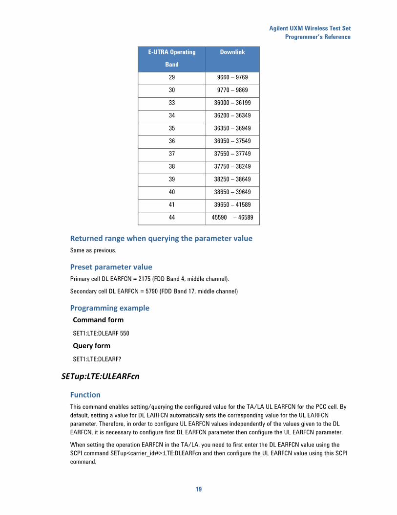
Allowed range when setting the parameter value
The following table provides the allowed ranges for this parameter (also included are the values for UL
EARFCN parameter):
E-UTRA Operating
Band
Downlink
1 0 – 599
2 600 - 1199
3 1200 – 1949
4 1950 – 2399
5 2400 – 2649
6 2650 – 2749
7 2750 – 3449
8 3450 – 3799
9 3800 – 4149
10 4150 – 4749
11 4750 – 4949
12 5010 - 5179
13 5180 – 5279
14 5280 – 5379
… …
17 5730 – 5849
18 5850 – 5999
19 6000 - 6149
20 6150 – 6449
21 6450 – 6599
… …
23 7500 – 7699
24 7700 – 8039
25 8040 – 8689
26 8690 – 9039
27 9040 – 9209
28 9210 – 9659
Agilent UXM Wireless Test Set
Programmer’s Reference
19
E-UTRA Operating
Band
Downlink
29 9660 – 9769
30 9770 – 9869
33 36000 – 36199
34 36200 – 36349
35 36350 – 36949
36 36950 – 37549
37 37550 – 37749
38 37750 – 38249
39 38250 – 38649
40 38650 – 39649
41 39650 – 41589
44 45590 – 46589
Returned range when querying the parameter value
Same as previous.
Preset parameter value
Primary cell DL EARFCN = 2175 (FDD Band 4, middle channel).
Secondary cell DL EARFCN = 5790 (FDD Band 17, middle channel)
Programming example
Command form
SET1:LTE:DLEARF 550
Query form
SET1:LTE:DLEARF?
SETup:LTE:ULEARFcn
Function
This command enables setting/querying the configured value for the TA/LA UL EARFCN for the PCC cell. By
default, setting a value for DL EARFCN automatically sets the corresponding value for the UL EARFCN
parameter. Therefore, in order to configure UL EARFCN values independently of the values given to the DL
EARFCN, it is necessary to configure first DL EARFCN parameter then configure the UL EARFCN parameter.
When setting the operation EARFCN in the TA/LA, you need to first enter the DL EARFCN value using the
SCPI command SETup<carrier_id#>:LTE:DLEARFcn and then configure the UL EARFCN value using this SCPI
command.
Agilent UXM Wireless Test Set
Programmer’s Reference
20
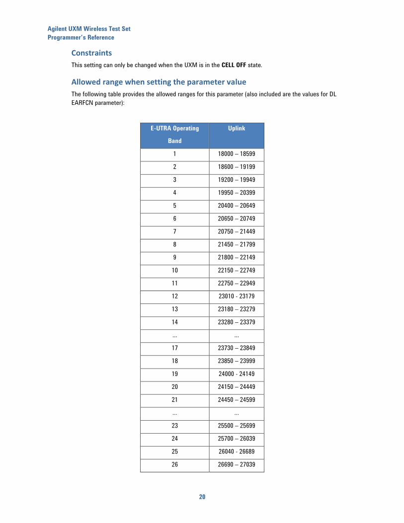
Constraints
This setting can only be changed when the UXM is in the CELL OFF state.
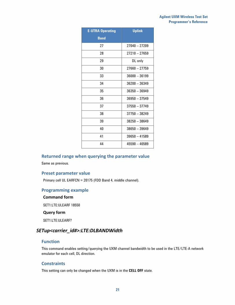
Allowed range when setting the parameter value
The following table provides the allowed ranges for this parameter (also included are the values for DL
EARFCN parameter):
E-UTRA Operating
Band
Uplink
1 18000 – 18599
2 18600 – 19199
3 19200 – 19949
4 19950 – 20399
5 20400 – 20649
6 20650 – 20749
7 20750 – 21449
8 21450 – 21799
9 21800 – 22149
10 22150 – 22749
11 22750 – 22949
12 23010 - 23179
13 23180 – 23279
14 23280 – 23379
… …
17 23730 – 23849
18 23850 – 23999
19 24000 - 24149
20 24150 – 24449
21 24450 – 24599
… …
23 25500 – 25699
24 25700 – 26039
25 26040 - 26689
26 26690 – 27039
Agilent UXM Wireless Test Set
Programmer’s Reference
21
E-UTRA Operating
Band
Uplink
27 27040 – 27209
28 27210 – 27659
29 DL only
30 27660 – 27759
33 36000 – 36199
34 36200 – 36349
35 36350 – 36949
36 36950 – 37549
37 37550 – 37749
38 37750 – 38249
39 38250 – 38649
40 38650 – 39649
41 39650 – 41589
44 45590 – 46589
Returned range when querying the parameter value
Same as previous.
Preset parameter value
Primary cell UL EARFCN = 20175 (FDD Band 4, middle channel).
Programming example
Command form
SET1:LTE:ULEARF 18550
Query form
SET1:LTE:ULEARF?
SETup<carrier_id#>:LTE:DLBANDWidth
Function
This command enables setting/querying the UXM channel bandwidth to be used in the LTE/LTE-A network
emulator for each cell, DL direction.
Constraints
This setting can only be changed when the UXM is in the CELL OFF state.
Agilent UXM Wireless Test Set
Programmer’s Reference
22
Allowed range when setting the parameter value
The following list provides the set of allowed values for this command: 1.4, 3, 5, 10, 15 and 20 MHz.
Returned range when querying the parameter value
Same as previous.
Preset parameter value
Default values for this parameter is 10 MHz.
Programming example
Command form
SET1:LTE:DLBANDW 1.4
Query form
SET2:LTE:DLBANDW?
SETup:LTE:ULBANDWidth
Function
This command enables setting/querying the channel bandwidth to be used in the LTE/LTE-A network
emulationor for the PCC cell, UL direction.
Constraints
This setting can only be changed when the UXM is in the CELL OFF state.
Allowed range when setting the parameter value
The following list provides the set of allowed values for this command: 1.4, 3, 5, 10, 15 and 20 MHz.
Returned range when querying the parameter value
Same as previous.
Preset parameter value
Default values for this parameter is 10 MHz.
Agilent UXM Wireless Test Set
Programmer’s Reference
23
Programming example
Command form
SET1:LTE:ULBANDW 1.4
Query form
SET1:LTE:ULBANDW?
SETup<carrier_id#>:LTE:CPSIZe
Function
This command enables setting/querying the cyclic prefix size to be used in the LTE/LTE-A network emulator
for each cell.
Constraints
This setting can only be changed when the UXM is in the CELL OFF state.
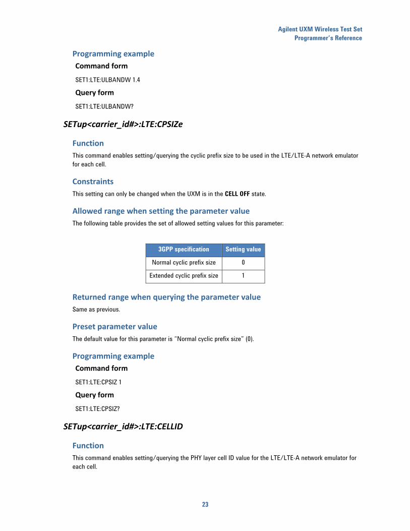
Allowed range when setting the parameter value
The following table provides the set of allowed setting values for this parameter:
3GPP specification Setting value
Normal cyclic prefix size 0
Extended cyclic prefix size 1
Returned range when querying the parameter value
Same as previous.
Preset parameter value
The default value for this parameter is “Normal cyclic prefix size” (0).
Programming example
Command form
SET1:LTE:CPSIZ 1
Query form
SET1:LTE:CPSIZ?
SETup<carrier_id#>:LTE:CELLID
Function
This command enables setting/querying the PHY layer cell ID value for the LTE/LTE-A network emulator for
each cell.
Agilent UXM Wireless Test Set
Programmer’s Reference
24
Constraints
This setting can only be changed when the UXM is in the CELL OFF state.
Allowed range when setting the parameter value
The allowed range of values when setting this parameter is 0 to 503.
Returned range when querying the parameter value
Same as previous.
Preset parameter value
For primary cell the default PHY layer cell ID value is 1.
For secondary cell the default PHY layer cell ID value is 3.
Programming example
Command form
SET1:LTE:CELLID 5
Query form
SET1:LTE:CELLID?
SETup<carrier_id#>:LTE:POWLVL
Function
This command enables setting/querying the configured RS EPRE level for the LTE/LTE-A network emulator
for each cell.
Allowed range when setting the parameter value
The range allowed for configuration in the TA/LA is -145 to -10 dBm/15 kHz.
Returned range when querying the parameter value
Same as above.
Preset parameter value
The default value for this parameter is -60 dBm/15 kHz.
Agilent UXM Wireless Test Set
Programmer’s Reference
25
Programming example
Command form
SET1:LTE:POWLVL -75
Query form
SET1:LTE:POWLVL?
SETup<carrier_id#>:LTE: TOTALPOWLVL
This command enables setting/querying the configured Channel BW power level for the LTE/LTE-A network
emulator for each cell. This parameter represents the integrated power level assuming all resource elements
in the bandwidth are occupied and transmitted at the same power level as the Reference Signals.
Allowed range when setting the parameter value
The range allowed for configuration in the TA/LA is -117.2 to 17.8 dBm/x MHz. Where “x” is the configured
bandwidth.
Returned range when querying the parameter value
Same as above.
Preset parameter value
The default value for this parameter is -32.2 dBm/10 MHz.
Command form
SET1:LTE:TOTALPOWLVL -32.2
Query form
SET1:LTE:TOTALPOWLVL?
SETup<carrier_id#>:LTE:SIMPATHLOSS
Function
This command enables configuring the value of the Reference Signal Power value for each cell, signaled in
the SIB2 broadcast message (within the PDSCH common configuration) as per the following formula:
Reference Signal Power = Simulated Path Loss + Cell Power Level
Constraints
This setting can only be changed when the UXM is in the CELL OFF state.
Allowed range when setting the parameter value
The Reference Signal Power field in the SIB2 broadcast message can take integer values or the same decimal
value as Cell Power within the -60 and 50 range.
Therefore, you must ensure that the set value for the Simulated Path Loss parameter, when added to the
currently configured Cell Power Level parameter value is within the above range.

Agilent UXM Wireless Test Set
Programmer’s Reference
26
Values outside the defined range are ignored.
Returned range when querying the parameter value
Same as above.
Preset parameter value
The default value for this parameter is 84 dB.
Programming example
Command form
SET1:LTE:SIMPATHLOSS -75
Query form
SET1:LTE:SIMPATHLOSS?
SETup<carrier_id#>:LTE:MCC
Function
Set/queries the Mobile Country Code to be used for the LTE/LTE-A network emulator for each cell.
Constraints
This setting can only be changed when the UXM is in the CELL OFF state.
Allowed range when setting the parameter value
0 to 999
Returned range when querying the parameter value
0 to 999
Preset parameter value
1
Programming example
Command form
SET1:LTE:MCC 1
Query form
SET1:LTE:MCC?
SETup<carrier_id#>:LTE:MNC
Function
Sets/queries the Mobile Network Code (MNC) to be used for the LTE/LTE-A network emulation for each cell.
Agilent UXM Wireless Test Set
Programmer’s Reference
27
Constraints
This setting can only be changed when the UXM is in the CELL OFF state.
Allowed range when setting the parameter value
0 to 999
Returned range when querying the parameter value
0 to 999
Preset parameter value
1
Programming example
Command form
SET1:LTE:MNC 1
Query form
SET1:LTE:MNC?
SETup:LTE:FRAMECFG
Function
This command enables setting/querying the configured value for the LTE TDD network emulation frame
configuration, which actually allows specifying the number of UL and DL subframes that are used when in
TDD operation.
This parameter is only applicable when in TDD operation, as commanded by parameter described in “CELL”
configuration commands.
Constraints
This setting can only be changed when the UXM is in the CELL OFF state.
Agilent UXM Wireless Test Set
Programmer’s Reference
28
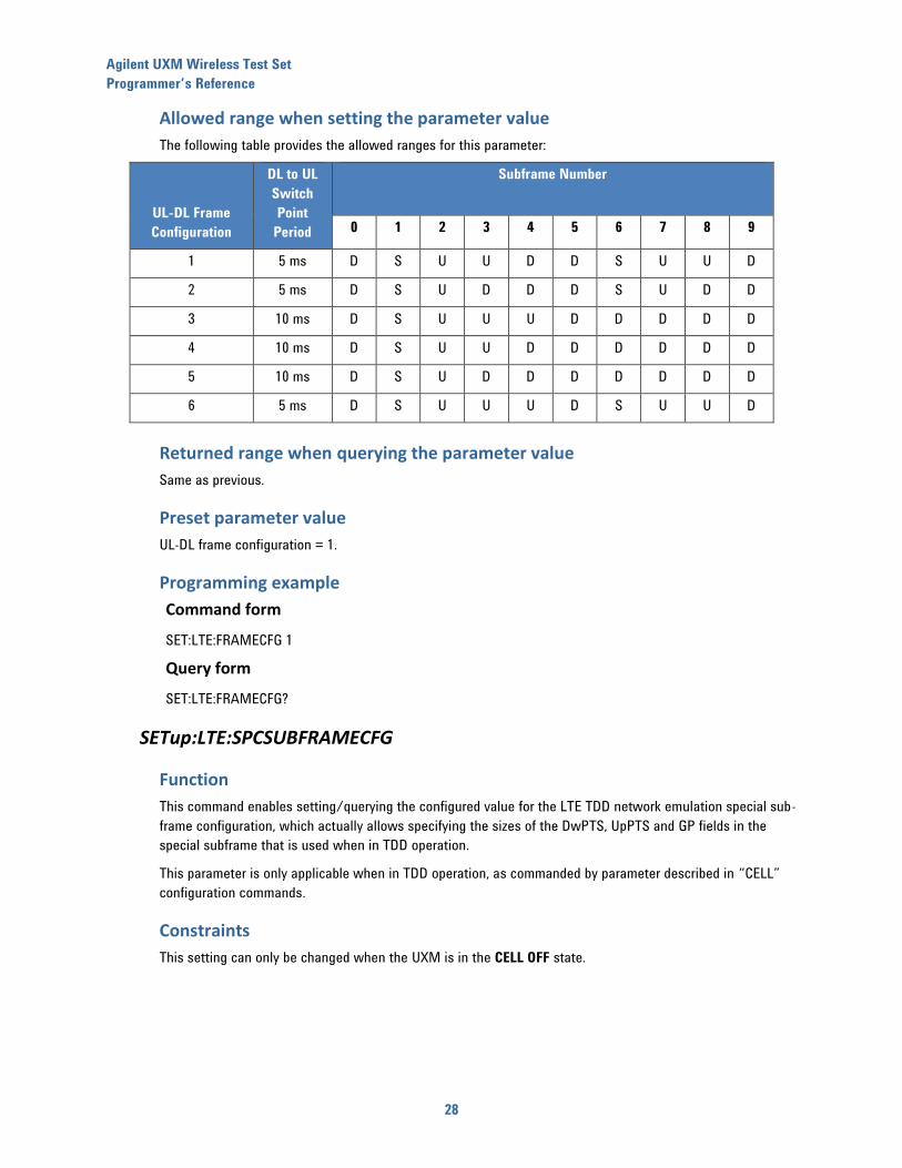
Allowed range when setting the parameter value
The following table provides the allowed ranges for this parameter:
UL-DL Frame
Configuration
DL to UL
Switch
Point
Period
Subframe Number
0 1 2 3 4 5 6 7 8 9
1 5 ms D S U U D D S U U D
2 5 ms D S U D D D S U D D
3 10 ms D S U U U D D D D D
4 10 ms D S U U D D D D D D
5 10 ms D S U D D D D D D D
6 5 ms D S U U U D S U U D
Returned range when querying the parameter value
Same as previous.
Preset parameter value
UL-DL frame configuration = 1.
Programming example
Command form
SET:LTE:FRAMECFG 1
Query form
SET:LTE:FRAMECFG?
SETup:LTE:SPCSUBFRAMECFG
Function
This command enables setting/querying the configured value for the LTE TDD network emulation special sub-
frame configuration, which actually allows specifying the sizes of the DwPTS, UpPTS and GP fields in the
special subframe that is used when in TDD operation.
This parameter is only applicable when in TDD operation, as commanded by parameter described in “CELL”
configuration commands.
Constraints
This setting can only be changed when the UXM is in the CELL OFF state.
Agilent UXM Wireless Test Set
Programmer’s Reference
29
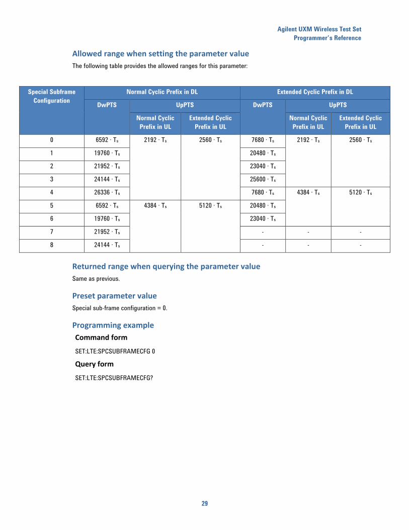
Allowed range when setting the parameter value
The following table provides the allowed ranges for this parameter:
Special Subframe
Configuration
Normal Cyclic Prefix in DL Extended Cyclic Prefix in DL
DwPTS UpPTS DwPTS UpPTS
Normal Cyclic
Prefix in UL
Extended Cyclic
Prefix in UL
Normal Cyclic
Prefix in UL
Extended Cyclic
Prefix in UL
0 6592 · Ts 2192 · Ts 2560 · Ts 7680 · Ts 2192 · Ts 2560 · Ts
1 19760 · Ts 20480 · Ts
2 21952 · Ts 23040 · Ts
3 24144 · Ts 25600 · Ts
4 26336 · Ts 7680 · Ts 4384 · Ts 5120 · Ts
5 6592 · Ts 4384 · Ts 5120 · Ts 20480 · Ts
6 19760 · Ts 23040 · Ts
7 21952 · Ts - - -
8 24144 · Ts - - -
Returned range when querying the parameter value
Same as previous.
Preset parameter value
Special sub-frame configuration = 0.
Programming example
Command form
SET:LTE:SPCSUBFRAMECFG 0
Query form
SET:LTE:SPCSUBFRAMECFG?

Agilent UXM Wireless Test Set
Programmer’s Reference
30
6 “Rel10” configuration commands
SETup:LTE:CARRIERAGGREGATION:STATE
Function
Sets/queries the carrier aggregation state to be used for the LTE/LTE-A network emulation.
Constraints
This setting can only be changed when the UXM is in the CELL OFF state.
Allowed range when setting the parameter value
Two settings are available:
0, carrier aggregation is disabled.
1, carrier aggregation is enabled.
Returned range when querying the parameter value
Same as previous.
Preset parameter value
0: Carrier aggregation is disabled.
Programming example
Command form
SET:LTE:CARRIERAGG:STAT 1
Query form
SET:LTE:CARRIERAGG:STAT?
SETup:LTE:SCCTIMINGdifference
Function
Sets/queries the SCC Timing difference values to be used for the LTE/LTE-A network emulation in carrier
aggregation.
Constraints
This setting can only be changed when the UXM is in the CELL OFF state. It is only applicable when carrier
aggregation is enabled.
Allowed range when setting the parameter value
Possible values for that parameter are integer values from -922 to +922. The units are “Ts”.
Returned range when querying the parameter value
Same as previous.
Agilent UXM Wireless Test Set
Programmer’s Reference
31
Preset parameter value
Default delay value is 0 Ts
Programming example
Command form
SET:LTE:SCCTIMING -10
Query form
SET:LTE:SCCTIMING?
SETup<carrier_id#>:LTE:CSIREFSIGNalsconfiguration:STATe
Function
Sets/queries the CSI Reference Signal state to be used for the LTE/LTE-A network emulation for each cell.
Constraints
This setting can only be changed when the UXM is in the CELL OFF state.
Allowed range when setting the parameter value
Two settings are available:
0, CSI Reference Signal is disabled.
1, CSI Reference Signal is enabled.
Returned range when querying the parameter value
Same as previous.
Preset parameter value
Default value is 0 (CSI Reference Signal disabled)
Programming example
Command form
SET1:LTE:CSIREFSIGN:STAT 1
Query form
SET1:LTE:CSIREFSIGN:STAT?
SETup<carrier_id#>:LTE:CSIREFSIGNalsconfiguration:ANTENNAPORTS
Function
Sets/queries the Antenna ports number in CSI Reference Signal, to be used for the LTE/LTE-A network
emulation for each cell.
Agilent UXM Wireless Test Set
Programmer’s Reference
32
Constraints
This setting can only be changed when the UXM is in the CELL OFF state. It is only applicable when CSI
Reference Signal is enabled.
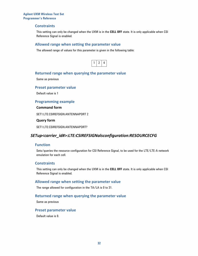
Allowed range when setting the parameter value
The allowed range of values for this parameter is given in the following table:
1 2 4
Returned range when querying the parameter value
Same as previous
Preset parameter value
Default value is 1
Programming example
Command form
SET1:LTE:CSIREFSIGN:ANTENNAPORT 2
Query form
SET1:LTE:CSIREFSIGN:ANTENNAPORT?
SETup<carrier_id#>:LTE:CSIREFSIGNalsconfiguration:RESOURCECFG
Function
Sets/queries the resource configuration for CSI Reference Signal, to be used for the LTE/LTE-A network
emulation for each cell.
Constraints
This setting can only be changed when the UXM is in the CELL OFF state. It is only applicable when CSI
Reference Signal is enabled.
Allowed range when setting the parameter value
The range allowed for configuration in the TA/LA is 0 to 31.
Returned range when querying the parameter value
Same as previous
Preset parameter value
Default value is 0.
Agilent UXM Wireless Test Set
Programmer’s Reference
33
Programming example
Command form
SET1:LTE:CSIREFSIGN:RESOURCECFG 20
Query form
SET1:LTE:CSIREFSIGN:RESOURCECFG?
SETup<carrier_id#>:LTE: CSIREFSIGNalsconfiguration:SUBFRAMECFG
Function
Sets/queries the subframe configuration for CSI Reference Signal, to be used for the LTE/LTE-A network
emulation for each cell.
Constraints
This setting can only be changed when the UXM is in the CELL OFF state. It is only applicable when CSI
Reference Signal is enabled.
Allowed range when setting the parameter value
The range allowed for configuration in the TA/LA is 0 to 154.
Returned range when querying the parameter value
Same as previous
Preset parameter value
Default value is 0
Programming example
Command form
SET1:LTE:CSIREFSIGN:SUBFRAMECFG 30
Query form
SET1:LTE:CSIREFSIGN:SUBFRAMECFG?
SETup<carrier_id#>:LTE:CSIREFSIGNalsconfiguration:PC
Function
Sets/queries the P-C configuration at CSI Reference Signal, to be used for the LTE/LTE-A network emulation
for each cell.
Constraints
This setting can only be changed when the UXM is in the CELL OFF state. It is only applicable when CSI
Reference Signal is enabled.

Agilent UXM Wireless Test Set
Programmer’s Reference
34
Allowed range when setting the parameter value
The range allowed for configuration in the TA/LA is -8 to 15 dB.
Returned range when querying the parameter value
Same as previous.
Preset parameter value
Default value is 0
Programming example
Command form
SET1:LTE:CSIREFSIGN:CSIREFSIGN:PC 4
Query form
SET1:LTE:CSIREFSIGN:PC?
SETup<carrier_id#>:LTE:CSIREFSIGNalsconfiguration:ZEROPOWer:RESOURCECFG
Function
Sets/queries the ZeroPower Resource configuration for CSI Reference Signal, to be used for the
LTE/LTE-A network emulation for each cell.
Constraints
This setting can only be changed when the UXM is in the CELL OFF state. It is only applicable when CSI
Reference Signal is enabled.
Allowed range when setting the parameter value
This parameter must be a bit string of 16 bits. Valid values are
• If FDD and Cyclic prefix is “Normal”: xxxxxxxxxx000000
• If FDD and Cyclic prefix is “Extended”: xxxxxxxx00000000
• If TDD, Antenna ports for data = < 2, and Cyclic prefix is “Normal”: xxxxxxxxxxxxxxxx
• If TDD, Antenna ports for data = 4, and Cyclic prefix is “Normal”: xxxxxxxxxx000000
• If TDD, Antenna ports for data = < 2, and Cyclic prefix is “Extended”: xxxxxxxxxxxxxx00
• If TDD, Antenna ports for data = 4, and Cyclic prefix is “Extended”: xxxxxxxx00000000
Returned range when querying the parameter value
Same as previous.
Preset parameter value
Default value is “0000000000000000”
Agilent UXM Wireless Test Set
Programmer’s Reference
35
Programming example
Command form
SET1:LTE:CSIREFSIGN:ZEROPOWer:RESOURCECFG “0101000000000000”
Query form
SET1:LTE:CSIREFSIGN:ZEROPOWer:RESOURCECFG?
SETup<carrier_id#>:LTE:CSIREFSIGNalsconfiguration:ZEROPOWer:SUBFRAMECFG
Function
Sets/queries the ZeroPower Subframe configuration for CSI Reference Signal, to be used for the LTE/LTE-A
network emulation for each cell.
Constraints
This setting can only be changed when the UXM is in the CELL OFF state. It is only applicable when CSI
Reference Signal is enabled.
Allowed range when setting the parameter value
The range allowed for configuration in the TA/LA is 0 to 154.
Returned range when querying the parameter value
Same as previous.
Preset parameter value
Default value is 0
Programming example
Command form
SET1:LTE:CSIREFSIGN:ZEROPOWer:SUBFRAMECFG 10
Query form
SET1:LTE:CSIREFSIGN:ZEROPOWer:SUBFRAMECFG?

Agilent UXM Wireless Test Set
Programmer’s Reference
36
7 “RMC” configuration commands
SETup<carrier_id#>:LTE:RMC:DL:TXMODe
Function
This parameter allows configuring the transmission mode to be used for DL allocations for each cell.
Constraints
This setting can only be changed when the UXM is in the CELL OFF state.
Allowed range when setting the parameter value
The following table provides the set of values allowed when setting this parameter:
Transmission
mode 1
0
Transmission
mode 2
1
Transmission
mode 3
2
Transmission
mode 4
3
Transmission
mode 6
5
Transmission
mode 7 SISO
6
Transmission
mode 7 MIMO
7
Transmission
mode 8
8
Note that transmission mode 1 is only applicable for single antenna configurations, whereas the remainding
transmission modes require multiple antenna configurations.
Returned range when querying the parameter value
Same as previous.
Preset parameter value
Default Transmission Mode is 0.

Agilent UXM Wireless Test Set
Programmer’s Reference
37
Programming example
Command form
SET1:LTE:RMC:DL:TXMOD 1
Query form
SET1:LTE:RMC:DL:TXMOD?
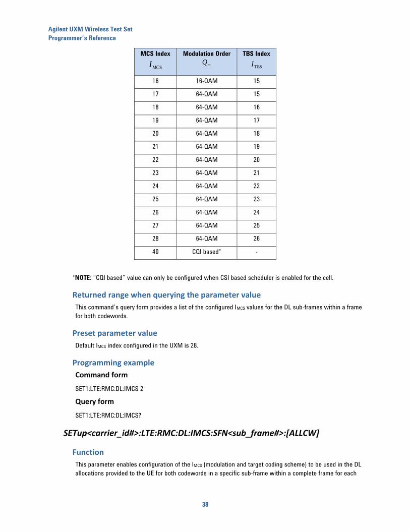
SETup<carrier_id#>:LTE:RMC:DL:IMCS[:ALL]
Function
This parameter enables configuration of the IMCS (modulation and target coding scheme) to be used in the DL
allocations provided to the UE. This command sets the provided IMCS to all DL sub-frames and codewords
within the frame for each cell. The configuration made through this command does not actually apply until
the related control commands to disconnect and connect again DL are executed (see section “Operation
Commands”).
Allowed range when setting the parameter value
The following table provides the set of values allowed when setting this parameter:
MCS Index
MCSI
Modulation Order
mQ
TBS Index
TBSI
0 QPSK 0
1 QPSK 1
2 QPSK 2
3 QPSK 3
4 QPSK 4
5 QPSK 5
6 QPSK 6
7 QPSK 7
8 QPSK 8
9 QPSK 9
10 16-QAM 9
11 16-QAM 10
12 16-QAM 11
13 16-QAM 12
14 16-QAM 13
15 16-QAM 14
Agilent UXM Wireless Test Set
Programmer’s Reference
38
MCS Index
MCSI
Modulation Order
mQ
TBS Index
TBSI
16 16-QAM 15
17 64-QAM 15
18 64-QAM 16
19 64-QAM 17
20 64-QAM 18
21 64-QAM 19
22 64-QAM 20
23 64-QAM 21
24 64-QAM 22
25 64-QAM 23
26 64-QAM 24
27 64-QAM 25
28 64-QAM 26
40 CQI based* -
*NOTE: “CQI based” value can only be configured when CSI based scheduler is enabled for the cell.
Returned range when querying the parameter value
This command’s query form provides a list of the configured IMCS values for the DL sub-frames within a frame
for both codewords.
Preset parameter value
Default IMCS index configured in the UXM is 28.
Programming example
Command form
SET1:LTE:RMC:DL:IMCS 2
Query form
SET1:LTE:RMC:DL:IMCS?
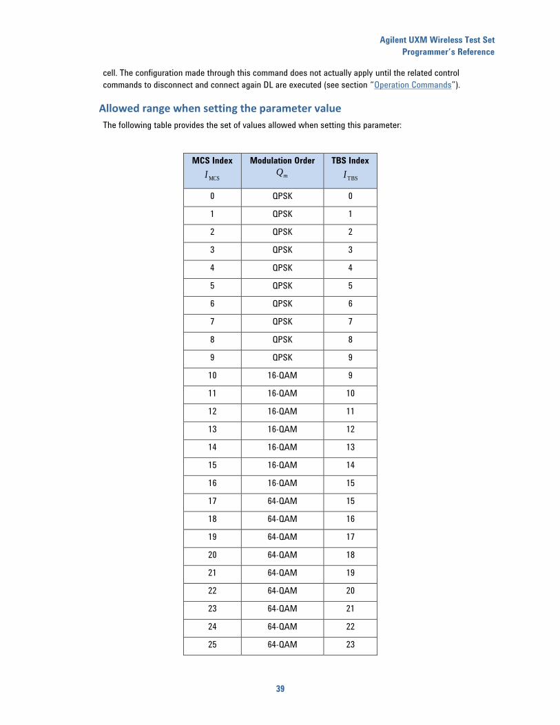
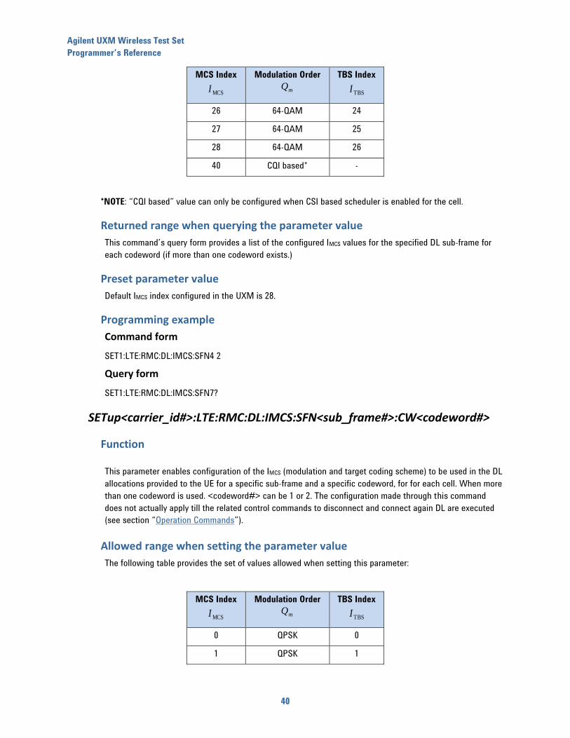
SETup<carrier_id#>:LTE:RMC:DL:IMCS:SFN<sub_frame#>:[ALLCW]
Function
This parameter enables configuration of the IMCS (modulation and target coding scheme) to be used in the DL
allocations provided to the UE for both codewords in a specific sub-frame within a complete frame for each
Agilent UXM Wireless Test Set
Programmer’s Reference
39
cell. The configuration made through this command does not actually apply until the related control
commands to disconnect and connect again DL are executed (see section “Operation Commands”).
Allowed range when setting the parameter value
The following table provides the set of values allowed when setting this parameter:
MCS Index
MCSI
Modulation Order
mQ
TBS Index
TBSI
0 QPSK 0
1 QPSK 1
2 QPSK 2
3 QPSK 3
4 QPSK 4
5 QPSK 5
6 QPSK 6
7 QPSK 7
8 QPSK 8
9 QPSK 9
10 16-QAM 9
11 16-QAM 10
12 16-QAM 11
13 16-QAM 12
14 16-QAM 13
15 16-QAM 14
16 16-QAM 15
17 64-QAM 15
18 64-QAM 16
19 64-QAM 17
20 64-QAM 18
21 64-QAM 19
22 64-QAM 20
23 64-QAM 21
24 64-QAM 22
25 64-QAM 23
Agilent UXM Wireless Test Set
Programmer’s Reference
40
MCS Index
MCSI
Modulation Order
mQ
TBS Index
TBSI
26 64-QAM 24
27 64-QAM 25
28 64-QAM 26
40 CQI based* -
*NOTE: “CQI based” value can only be configured when CSI based scheduler is enabled for the cell.
Returned range when querying the parameter value
This command’s query form provides a list of the configured IMCS values for the specified DL sub-frame for
each codeword (if more than one codeword exists.)
Preset parameter value
Default IMCS index configured in the UXM is 28.
Programming example
Command form
SET1:LTE:RMC:DL:IMCS:SFN4 2
Query form
SET1:LTE:RMC:DL:IMCS:SFN7?
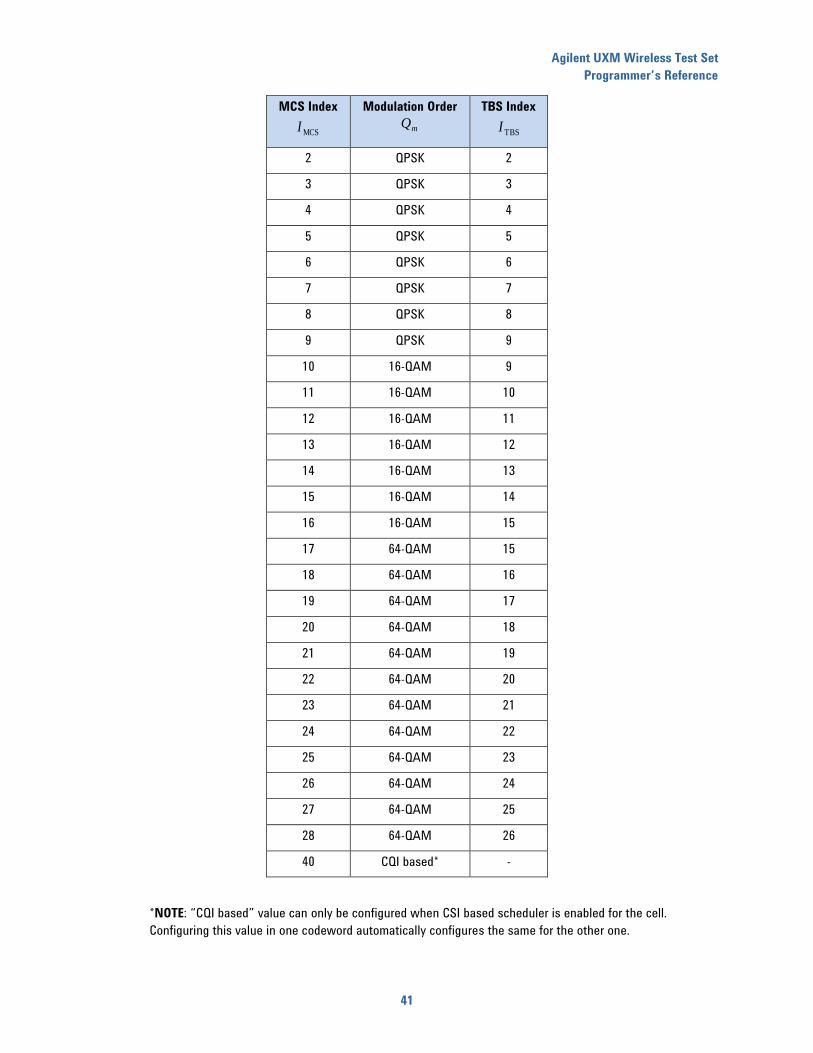
SETup<carrier_id#>:LTE:RMC:DL:IMCS:SFN<sub_frame#>:CW<codeword#>
Function
This parameter enables configuration of the IMCS (modulation and target coding scheme) to be used in the DL
allocations provided to the UE for a specific sub-frame and a specific codeword, for for each cell. When more
than one codeword is used. <codeword#> can be 1 or 2. The configuration made through this command
does not actually apply till the related control commands to disconnect and connect again DL are executed
(see section “Operation Commands”).
Allowed range when setting the parameter value
The following table provides the set of values allowed when setting this parameter:
MCS Index
MCSI
Modulation Order
mQ
TBS Index
TBSI
0 QPSK 0
1 QPSK 1
Agilent UXM Wireless Test Set
Programmer’s Reference
41
MCS Index
MCSI
Modulation Order
mQ
TBS Index
TBSI
2 QPSK 2
3 QPSK 3
4 QPSK 4
5 QPSK 5
6 QPSK 6
7 QPSK 7
8 QPSK 8
9 QPSK 9
10 16-QAM 9
11 16-QAM 10
12 16-QAM 11
13 16-QAM 12
14 16-QAM 13
15 16-QAM 14
16 16-QAM 15
17 64-QAM 15
18 64-QAM 16
19 64-QAM 17
20 64-QAM 18
21 64-QAM 19
22 64-QAM 20
23 64-QAM 21
24 64-QAM 22
25 64-QAM 23
26 64-QAM 24
27 64-QAM 25
28 64-QAM 26
40 CQI based* -
*NOTE: “CQI based” value can only be configured when CSI based scheduler is enabled for the cell.
Configuring this value in one codeword automatically configures the same for the other one.
Agilent UXM Wireless Test Set
Programmer’s Reference
42
Returned range when querying the parameter value
This command’s query form provides the value of the configured IMCS values for the specified DL sub-frame
and codeword.
Preset parameter value
Default IMCS index configured in the UXM is 28.
Programming example
Command form
SET1:LTE:RMC:DL:IMCS:SFN3:CW2 4
Query form
SET1:LTE:RMC:DL:IMCS:SFN3:CW2?
SETup<carrier_id#>:LTE:RMC:DL:FRAMEREPetitionperiod
Function
This command enables specifying how often the currently configured frame-based DL RMC is repeated for
each cell. The configuration made through this command does not actually apply until the related control
commands to disconnect and connect again DL are executed (see section “Operation Commands”).
Allowed range when setting the parameter value
This command enables configuring repetition periods of 1 (UE is allocated in DL every frame) to 100 frames.
Returned range when querying the parameter value
Same as above.
Preset parameter value
Default frame repetition period is 1.
Programming example
Command form
SET1:LTE:RMC:DL:FRAMEREP 5
Query form
SET1:LTE:RMC:DL:FRAMEREP?
SETup<carrier_id#>:LTE:RMC:DL:ALLOCSIZe[:ALL]
Function
This parameter enables configuration of the size of the allocation to be provided to the UE for each cell,
specifying the number of PRBs, for the DL direction, to be allocated in all sub-frames. The configuration
made through this command does not actually apply until the related control commands to disconnect and
connect again DL are executed (see section “Operation Commands”).
Agilent UXM Wireless Test Set
Programmer’s Reference
43
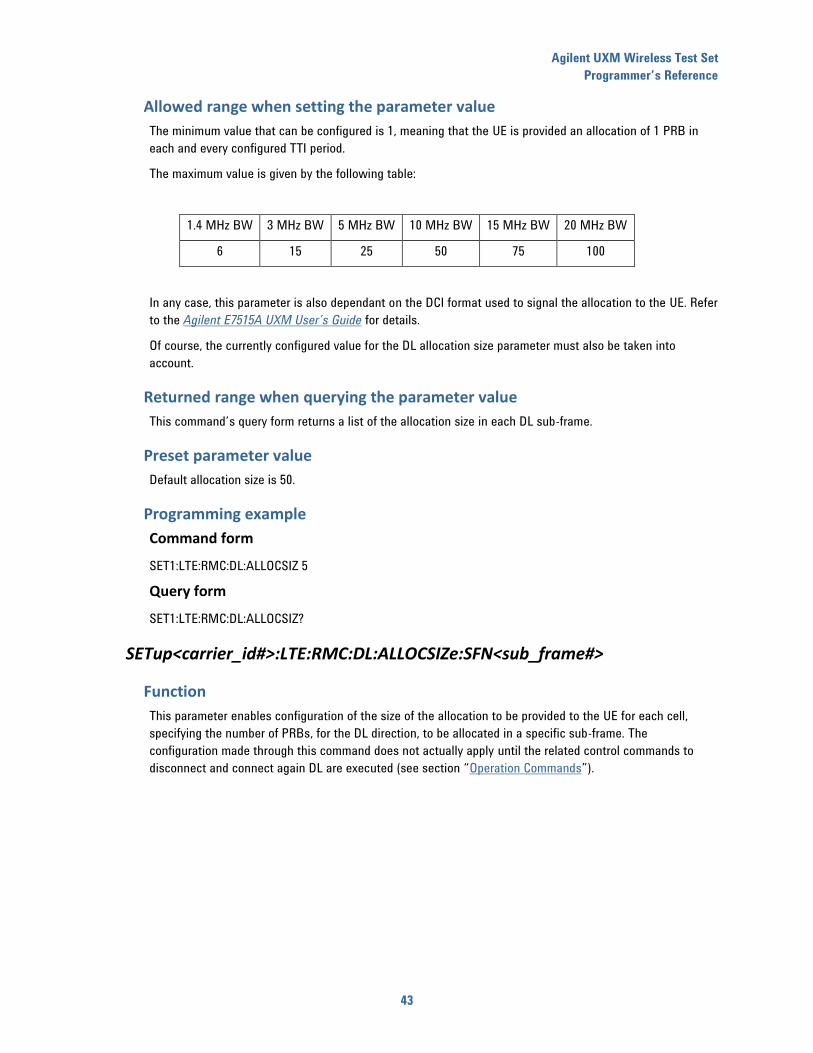
Allowed range when setting the parameter value
The minimum value that can be configured is 1, meaning that the UE is provided an allocation of 1 PRB in
each and every configured TTI period.
The maximum value is given by the following table:
1.4 MHz BW 3 MHz BW 5 MHz BW 10 MHz BW 15 MHz BW 20 MHz BW
6 15 25 50 75 100
In any case, this parameter is also dependant on the DCI format used to signal the allocation to the UE. Refer
to the Agilent E7515A UXM User’s Guide for details.
Of course, the currently configured value for the DL allocation size parameter must also be taken into
account.
Returned range when querying the parameter value
This command’s query form returns a list of the allocation size in each DL sub-frame.
Preset parameter value
Default allocation size is 50.
Programming example
Command form
SET1:LTE:RMC:DL:ALLOCSIZ 5
Query form
SET1:LTE:RMC:DL:ALLOCSIZ?
SETup<carrier_id#>:LTE:RMC:DL:ALLOCSIZe:SFN<sub_frame#>
Function
This parameter enables configuration of the size of the allocation to be provided to the UE for each cell,
specifying the number of PRBs, for the DL direction, to be allocated in a specific sub-frame. The
configuration made through this command does not actually apply until the related control commands to
disconnect and connect again DL are executed (see section “Operation Commands”).
Agilent UXM Wireless Test Set
Programmer’s Reference
44
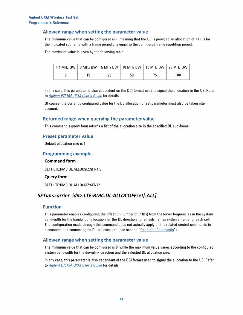
Allowed range when setting the parameter value
The minimum value that can be configured is 1, meaning that the UE is provided an allocation of 1 PRB for
the indicated subframe with a frame periodicity equal to the configured frame repetition period.
The maximum value is given by the following table:
1.4 MHz BW 3 MHz BW 5 MHz BW 10 MHz BW 15 MHz BW 20 MHz BW
6 15 25 50 75 100
In any case, this parameter is also dependent on the DCI format used to signal the allocation to the UE. Refer
to Agilent E7515A UXM User’s Guide for details.
Of course, the currently configured value for the DL allocation offset parameter must also be taken into
account.
Returned range when querying the parameter value
This command’s query form returns a list of the allocation size in the specified DL sub-frame.
Preset parameter value
Default allocation size is 1.
Programming example
Command form
SET1:LTE:RMC:DL:ALLOCSIZ:SFN4 5
Query form
SET1:LTE:RMC:DL:ALLOCSIZ:SFN7?
SETup<carrier_id#>:LTE:RMC:DL:ALLOCOFFset[:ALL]
Function
This parameter enables configuring the offset (in number of PRBs) from the lower frequencies in the system
bandwidth for the bandwidth allocation for the DL direction, for all sub-frames within a frame for each cell.
The configuration made through this command does not actually apply till the related control commands to
disconnect and connect again DL are executed (see section “Operation Commands”).
Allowed range when setting the parameter value
The minimum value that can be configured is 0, while the maximum value varies according to the configured
system bandwidth for the downlink direction and the selected DL allocation size.
In any case, this parameter is also dependant of the DCI format used to signal the allocation to the UE. Refer
to Agilent E7515A UXM User’s Guide for details.

Agilent UXM Wireless Test Set
Programmer’s Reference
45
Returned range when querying the parameter value
This command’s query form returns a list of the configured allocation offsets for all sub-frames in DL
direction.
Preset parameter value
Default DL allocation offset is 50.
Programming example
Command form
SET1:LTE:RMC:DL:ALLOCOFF 10
Query form
SET1:LTE:RMC:DL:ALLOCOFF?
SETup<carrier_id #>:LTE:RMC:DL:ALLOCOFFset:SFN<sub_frame#>
Function
This parameter enables configuration of the offset (in number of PRBs) from the lower frequencies in the
system bandwidth for the bandwidth allocation for the DL direction, for the specified sub-frame within a
frame for each cell. The configuration made through this command does not actually apply until the related
control commands to disconnect and connect again DL are executed (see section “Operation Commands”).
Allowed range when setting the parameter value
The minimum value that can be configured is 0, while the maximum value varies according to the configured
system bandwidth for the downlink direction and the selected DL allocation size.
In any case, this parameter is also dependant of the DCI format used to signal the allocation to the UE. Refer
to Agilent E7515A UXM User’s Guide for details.
Returned range when querying the parameter value
This command’s query form returns a list of the configured allocation offsets for all sub-frames in DL
direction.
Preset parameter value
Default DL allocation offset is 0.
Programming example
Command form
SET1:LTE:RMC:DL:ALLOCOFF:SFN4 10
Query form
SET1:LTE:RMC:DL:ALLOCOFF:SFN7?

Agilent UXM Wireless Test Set
Programmer’s Reference
46
SETup<carrier_id#>:LTE:RMC:DL:ALLOCBITMAP[:ALL]
Function
This parameter enables configuration of non-consecutive allocation of Resource Block Groups in the DL for
each cell, when the transmission mode selected allows you to do this. The configuration made through this
command does not actually apply until the related control commands to disconnect and connect again (DL)
are executed (see section “Operation Commands”).
Allowed range when setting the parameter value
This parameter must be a bit string where the length depends on the bandwidth configured in the system:
6 bits, in case of BW = 1.4 MHz
8 bits, in case of BW = 3MHz
13 bits, in case of BW = 5MHz
17 bits, in case of BW = 10MHz
19 bits, in case of BW = 15MHz
25 bits, in case of BW = 20MHz
Returned range when querying the parameter value
Same as previous.
Preset parameter value
Default IMCS index configured in the system is “11111111111111111”
Programming example
Command form
SET1:LTE:RMC:DL:ALLOCBITMAP:ALL “10101111111111110”
Query form
SET1:LTE:RMC:DL:ALLOCBITMAP:ALL?
SETup<carrier_id#>:LTE:RMC:DL:ALLOCBITMAP:SFN<sub_frame#>
Function
This parameter enables configuration of the non-consecutive allocation of Resource Block Groups for a
specific sub-frame within a complete frame for each cell, when the transmission mode selected in the cell
allows you to do this. The configuration made through this command does not actually apply until the related
control commands to disconnect and connect again (DL) are executed (see section “Operation Commands”).
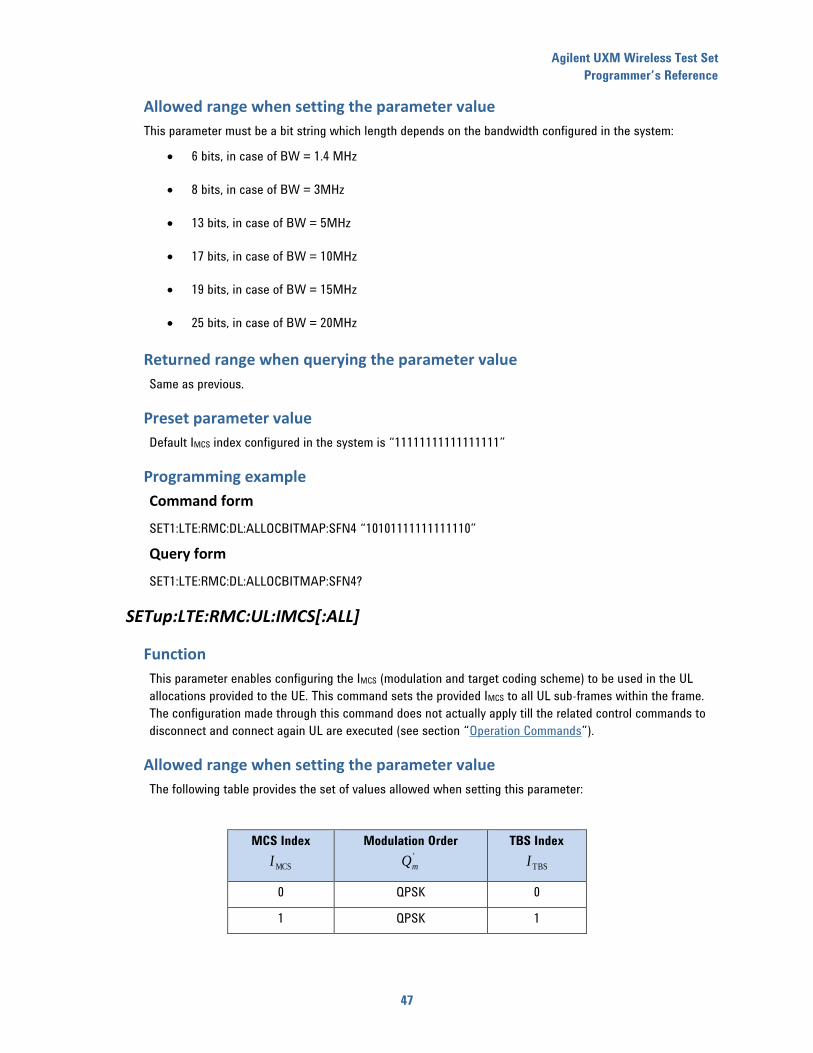
Agilent UXM Wireless Test Set
Programmer’s Reference
47
Allowed range when setting the parameter value
This parameter must be a bit string which length depends on the bandwidth configured in the system:
6 bits, in case of BW = 1.4 MHz
8 bits, in case of BW = 3MHz
13 bits, in case of BW = 5MHz
17 bits, in case of BW = 10MHz
19 bits, in case of BW = 15MHz
25 bits, in case of BW = 20MHz
Returned range when querying the parameter value
Same as previous.
Preset parameter value
Default IMCS index configured in the system is “11111111111111111”
Programming example
Command form
SET1:LTE:RMC:DL:ALLOCBITMAP:SFN4 “10101111111111110”
Query form
SET1:LTE:RMC:DL:ALLOCBITMAP:SFN4?
SETup:LTE:RMC:UL:IMCS[:ALL]
Function
This parameter enables configuring the IMCS (modulation and target coding scheme) to be used in the UL
allocations provided to the UE. This command sets the provided IMCS to all UL sub-frames within the frame.
The configuration made through this command does not actually apply till the related control commands to
disconnect and connect again UL are executed (see section “Operation Commands”).
Allowed range when setting the parameter value
The following table provides the set of values allowed when setting this parameter:
MCS Index
MCSI
Modulation Order '
mQ
TBS Index
TBSI
0 QPSK 0
1 QPSK 1

Agilent UXM Wireless Test Set
Programmer’s Reference
48
MCS Index
MCSI
Modulation Order '
mQ
TBS Index
TBSI
2 QPSK 2
3 QPSK 3
4 QPSK 4
5 QPSK 5
6 QPSK 6
7 QPSK 7
8 QPSK 8
9 QPSK 9
10 QPSK 10
11 16-QAM 10
12 16-QAM 11
13 16-QAM 12
14 16-QAM 13
15 16-QAM 14
16 16-QAM 15
17 16-QAM 16
18 16-QAM 17
19 16-QAM 18
20 16-QAM 19
21 64-QAM 19
22 64-QAM 20
23 64-QAM 21
24 64-QAM 22
25 64-QAM 23
26 64-QAM 24
27 64-QAM 25
28 64-QAM 26
Note that, according to the 3GPP specifications, support of 64QAM modulation is not mandatory for the UE.
Returned range when querying the parameter value
This command’s query form provides a list of the configured IMCS values for the UL sub-frames within a frame.
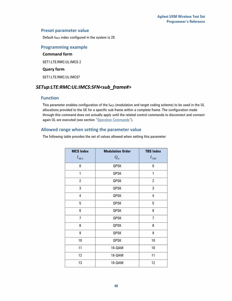
Agilent UXM Wireless Test Set
Programmer’s Reference
49
Preset parameter value
Default IMCS index configured in the system is 20.
Programming example
Command form
SET1:LTE:RMC:UL:IMCS 2
Query form
SET1:LTE:RMC:UL:IMCS?
SETup:LTE:RMC:UL:IMCS:SFN<sub_frame#>
Function
This parameter enables configuration of the IMCS (modulation and target coding scheme) to be used in the UL
allocations provided to the UE for a specific sub-frame within a complete frame. The configuration made
through this command does not actually apply until the related control commands to disconnect and connect
again UL are executed (see section “Operation Commands”).
Allowed range when setting the parameter value
The following table provides the set of values allowed when setting this parameter:
MCS Index
MCSI
Modulation Order '
mQ
TBS Index
TBSI
0 QPSK 0
1 QPSK 1
2 QPSK 2
3 QPSK 3
4 QPSK 4
5 QPSK 5
6 QPSK 6
7 QPSK 7
8 QPSK 8
9 QPSK 9
10 QPSK 10
11 16-QAM 10
12 16-QAM 11
13 16-QAM 12
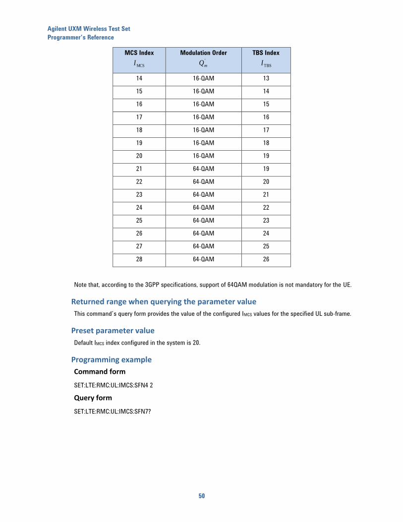
Agilent UXM Wireless Test Set
Programmer’s Reference
50
MCS Index
MCSI
Modulation Order '
mQ
TBS Index
TBSI
14 16-QAM 13
15 16-QAM 14
16 16-QAM 15
17 16-QAM 16
18 16-QAM 17
19 16-QAM 18
20 16-QAM 19
21 64-QAM 19
22 64-QAM 20
23 64-QAM 21
24 64-QAM 22
25 64-QAM 23
26 64-QAM 24
27 64-QAM 25
28 64-QAM 26
Note that, according to the 3GPP specifications, support of 64QAM modulation is not mandatory for the UE.
Returned range when querying the parameter value
This command’s query form provides the value of the configured IMCS values for the specified UL sub-frame.
Preset parameter value
Default IMCS index configured in the system is 20.
Programming example
Command form
SET:LTE:RMC:UL:IMCS:SFN4 2
Query form
SET:LTE:RMC:UL:IMCS:SFN7?

Agilent UXM Wireless Test Set
Programmer’s Reference
51
SETup:LTE:RMC:UL:FRAMEREPetitionperiod
Function
This command enables specifying how often the currently configured frame-based UL RMC is repeated. The
configuration made through this command does not actually apply till the related control commands to
disconnect and connect again UL are executed (see section “Operation Commands”).
Allowed range when setting the parameter value
This command enables configuring repetition periods of 1 (UE is allocated in UL every frame) to 100 frames.
Returned range when querying the parameter value
Same as previous.
Preset parameter value
Default frame repetition period is 1.
Programming example
Command form
SET:LTE:RMC:UL:FRAMEREP 5
Query form
SET:LTE:RMC:UL:FRAMEREP?
SETup:LTE:RMC:UL:ALLOCSIZe[:ALL]
Function
This parameter enables configuration of the size of the allocation to be provided to the UE, specifying the
number of PRBs, for the UL direction, to be allocated in all sub-frames. The configuration made through this
command does not actually apply until the related control commands to disconnect and connect again UL
are executed (see section “Operation Commands”).
Allowed range when setting the parameter value
The minimum value that can be configured is 1, meaning that the UE is provided an allocation of 1 PRB in
each and every configured TTI period.
The maximum value is given by the following table:
1.4 MHz BW 3 MHz BW 5 MHz BW 10 MHz BW 15 MHz BW 20 MHz BW
6 15 25 50 75 100
Of course, the currently configured value for the UL allocation offset parameter must also be taken into
account.
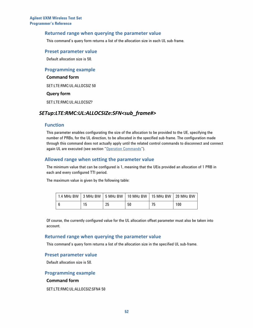
Agilent UXM Wireless Test Set
Programmer’s Reference
52
Returned range when querying the parameter value
This command’s query form returns a list of the allocation size in each UL sub-frame.
Preset parameter value
Default allocation size is 50.
Programming example
Command form
SET:LTE:RMC:UL:ALLOCSIZ 50
Query form
SET:LTE:RMC:UL:ALLOCSIZ?
SETup:LTE:RMC:UL:ALLOCSIZe:SFN<sub_frame#>
Function
This parameter enables configurating the size of the allocation to be provided to the UE, specifying the
number of PRBs, for the UL direction, to be allocated in the specified sub-frame. The configuration made
through this command does not actually apply until the related control commands to disconnect and connect
again UL are executed (see section “Operation Commands”).
Allowed range when setting the parameter value
The minimum value that can be configured is 1, meaning that the UEis provided an allocation of 1 PRB in
each and every configured TTI period.
The maximum value is given by the following table:
1.4 MHz BW 3 MHz BW 5 MHz BW 10 MHz BW 15 MHz BW 20 MHz BW
6 15 25 50 75 100
Of course, the currently configured value for the UL allocation offset parameter must also be taken into
account.
Returned range when querying the parameter value
This command’s query form returns a list of the allocation size in the specified UL sub-frame.
Preset parameter value
Default allocation size is 50.
Programming example
Command form
SET:LTE:RMC:UL:ALLOCSIZ:SFN4 50

Agilent UXM Wireless Test Set
Programmer’s Reference
53
Query form
SET:LTE:RMC:UL:ALLOCSIZ:SFN7?
SETup:LTE:RMC:UL:ALLOCOFFset[:ALL]
Function
This parameter enables configuration of the offset (in number of PRBs) from the lower frequencies in the
system bandwidth for the bandwidth allocation for the UL direction, for all sub-frames within a frame. The
configuration made through this command does not actually apply until the related control commands to
disconnect and connect again UL are executed (see section “Operation Commands”).
Allowed range when setting the parameter value
The minimum value that can be configured is 0, while the maximum value varies according to the configured
system bandwidth for the uplink direction and the selected UL allocation size.
Returned range when querying the parameter value
This command’s query form returns a list of the configured allocation offsets for all sub-frames in UL
direction.
Preset parameter value
Default DL allocation offset is 0.
Programming example
Command form
SET:LTE:RMC:UL:ALLOCOFF 5
Query form
SET:LTE:RMC:UL:ALLOCOFF?
SETup:LTE:RMC:UL:ALLOCOFFset:SFN<sub_frame#>
Function
This parameter enables configuring the offset (in number of PRBs) from the lower frequencies in the system
bandwidth for the bandwidth allocation for the UL direction, for the specified sub-frame within a frame. The
configuration made through this command does not actually apply until the related control commands to
disconnect and connect again UL are executed (see section “Operation Commands”).
Allowed range when setting the parameter value
The minimum value that can be configured is 0, while the maximum value varies according to the configured
system bandwidth for the uplink direction and the selected UL allocation size.
Returned range when querying the parameter value
This command’s query form returns a list of the configured allocation offsets for the specified sub-frame in
UL direction.

Agilent UXM Wireless Test Set
Programmer’s Reference
54
Preset parameter value
Default DL allocation offset is 0.
Programming example
Command form
SET:LTE:RMC:UL:ALLOCOFF:SFN4 5
Query form
SET:LTE:RMC:UL:ALLOCOFF:SFN7?
SETup:LTE:RMC:UL:CSI[:ALL]
Function
This parameter enables activating or deactivating CSI request in UL.
Allowed range when setting the parameter value
Two settings are available:
0, CSI report not required in UL.
1, CSI report on Serving cell required.
Returned range when querying the parameter value
Same as previous.
Preset parameter value
Default value is 0 (CSI request disabled).
Programming example
Command form
SET:LTE:RMC:UL:CSI 1
Query form
SET:LTE:RMC: UL:CSI?
SETup:LTE:RMC:UL:CSI:SFN<sub_frame#>
Function
This parameter indicates the subframes in which the CQI reports are requested to the UE.
Agilent UXM Wireless Test Set
Programmer’s Reference
55
Allowed range when setting the parameter value
Two settings are available:
0, CSI report not required in that subframe.
1, CSI report on Serving cell required.
Returned range when querying the parameter value
Same as previous.
Preset parameter value
Default value is 0 (CSI request disabled).
Programming example
Command form
SET:LTE:RMC:UL:CSI:SFN3 1
Query form
SET:LTE:RMC: UL:CSI:SFN3?
SETup:LTE:RMC:CROSSCHEDuling
Function
This parameter enables activating or deactivating cross scheduling mode for the SCC resources allocation
when carrier aggregation is used.
This parameter can only be changed when the LTE/LTE-A network emulation is in the idle state.
Constraints
This setting can only be changed when the system is in the CELL OFF state.
Allowed range when setting the parameter value
Two settings are available:
0, SCC cross scheduling disabled.
1, SCC cross scheduling enabled.
Returned range when querying the parameter value
Same as previous.
Preset parameter value
Default value is 0 (cross scheduling disabled).
Agilent UXM Wireless Test Set
Programmer’s Reference
56
Programming example
Command form
SET:LTE:RMC:CROSSCHED 1
Query form
SET:LTE:RMC:CROSSCHED?
SETup<carrier_id#>:LTE:RMC:CQISCHEDuling:STATe
Function
This parameter enables activating or deactivating the CSI based scheduler for each cell.
Constraints
This setting can only be enabled when the CQI/PMI/RI reports are activated in the cell configuration.
Allowed range when setting the parameter value
Two settings are available:
0, CSI based scheduler disabled.
1, CSI based scheduler enabled.
Returned range when querying the parameter value
Same as previous.
Preset parameter value
Default value is 0 (CSI based scheduler disabled).
Programming example
Command form
SET:LTE:RMC:CQISCHED:STAT 1
Query form
SET:LTE:RMC:CQISCHED:STAT?
SETup<carrier_id#>:LTE:RMC:CQISCHEDuling:PRECODINGMODE
Function
This parameter enables configuring the PMI/RI mode to be used for the CSI based scheduler.
Constraints
This setting can only be changed when the CSI based scheduler is enabled and under certain Transmission
Modes.
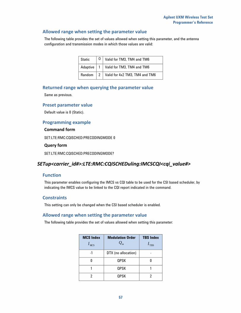
Agilent UXM Wireless Test Set
Programmer’s Reference
57
Allowed range when setting the parameter value
The following table provides the set of values allowed when setting this parameter, and the antenna
configuration and transmission modes in which those values are valid:
Static 0 Valid for TM3, TM4 and TM6
Adaptive 1 Valid for TM3, TM4 and TM6
Random 2 Valid for 4x2 TM3, TM4 and TM6
Returned range when querying the parameter value
Same as previous.
Preset parameter value
Default value is 0 (Static).
Programming example
Command form
SET:LTE:RMC:CQISCHED:PRECODINGMODE 0
Query form
SET:LTE:RMC:CQISCHED:PRECODINGMODE?
SETup<carrier_id#>:LTE:RMC:CQISCHEDuling:IMCSCQI<cqi_value#>
Function
This parameter enables configuring the IMCS vs CQI table to be used for the CSI based scheduler, by
indicating the IMCS value to be linked to the CQI report indicated in the command.
Constraints
This setting can only be changed when the CSI based scheduler is enabled.
Allowed range when setting the parameter value
The following table provides the set of values allowed when setting this parameter:
MCS Index
MCSI
Modulation Order
mQ
TBS Index
TBSI
-1 DTX (no allocation) -
0 QPSK 0
1 QPSK 1
2 QPSK 2

Agilent UXM Wireless Test Set
Programmer’s Reference
58
MCS Index
MCSI
Modulation Order
mQ
TBS Index
TBSI
3 QPSK 3
4 QPSK 4
5 QPSK 5
6 QPSK 6
7 QPSK 7
8 QPSK 8
9 QPSK 9
10 16-QAM 9
11 16-QAM 10
12 16-QAM 11
13 16-QAM 12
14 16-QAM 13
15 16-QAM 14
16 16-QAM 15
17 64-QAM 15
18 64-QAM 16
19 64-QAM 17
20 64-QAM 18
21 64-QAM 19
22 64-QAM 20
23 64-QAM 21
24 64-QAM 22
25 64-QAM 23
26 64-QAM 24
27 64-QAM 25
28 64-QAM 26
Returned range when querying the parameter value
Same as previous.
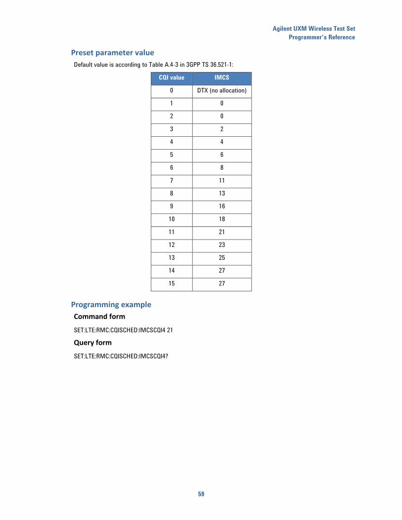
Agilent UXM Wireless Test Set
Programmer’s Reference
59
Preset parameter value
Default value is according to Table A.4-3 in 3GPP TS 36.521-1:
CQI value IMCS
0 DTX (no allocation)
1 0
2 0
3 2
4 4
5 6
6 8
7 11
8 13
9 16
10 18
11 21
12 23
13 25
14 27
15 27
Programming example
Command form
SET:LTE:RMC:CQISCHED:IMCSCQI4 21
Query form
SET:LTE:RMC:CQISCHED:IMCSCQI4?
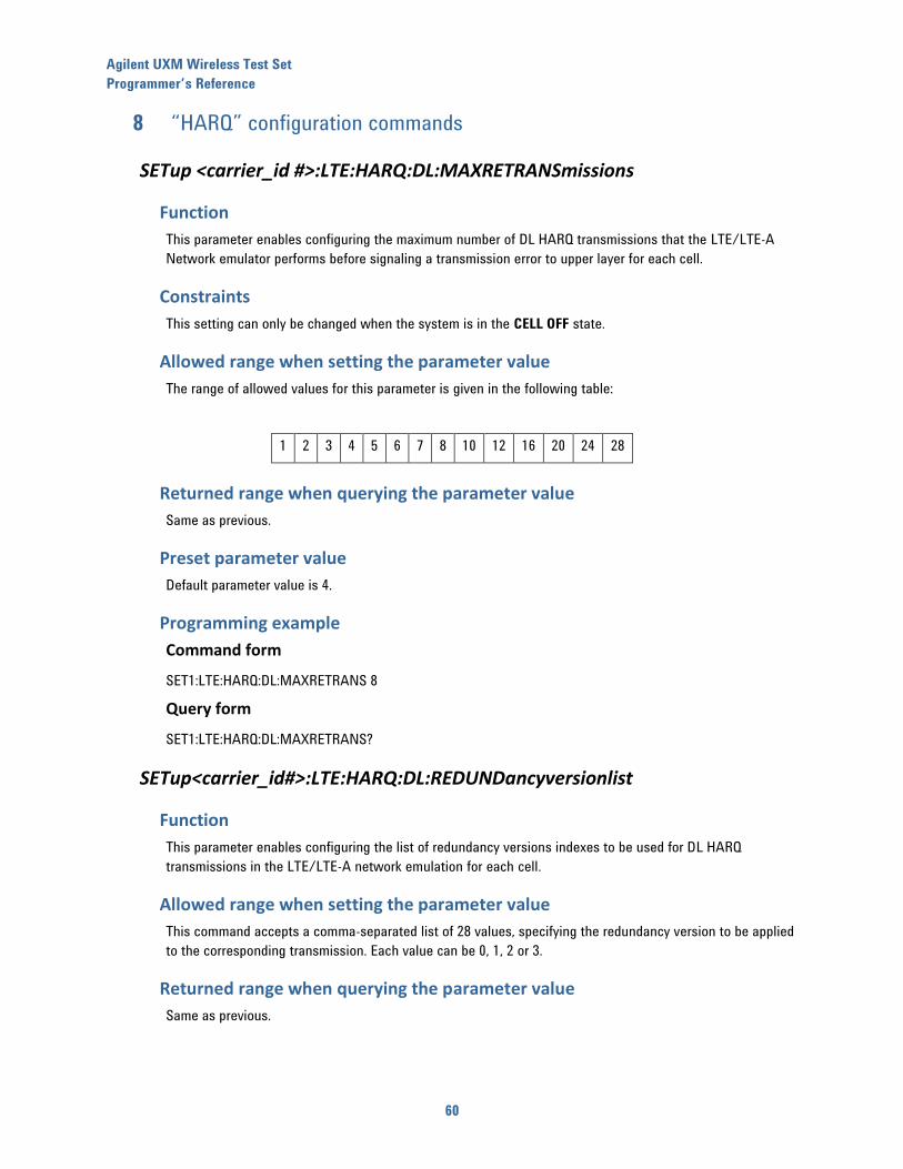
Agilent UXM Wireless Test Set
Programmer’s Reference
60
8 “HARQ” configuration commands
SETup <carrier_id #>:LTE:HARQ:DL:MAXRETRANSmissions
Function
This parameter enables configuring the maximum number of DL HARQ transmissions that the LTE/LTE-A
Network emulator performs before signaling a transmission error to upper layer for each cell.
Constraints
This setting can only be changed when the system is in the CELL OFF state.
Allowed range when setting the parameter value
The range of allowed values for this parameter is given in the following table:
1 2 3 4 5 6 7 8 10 12 16 20 24 28
Returned range when querying the parameter value
Same as previous.
Preset parameter value
Default parameter value is 4.
Programming example
Command form
SET1:LTE:HARQ:DL:MAXRETRANS 8
Query form
SET1:LTE:HARQ:DL:MAXRETRANS?
SETup<carrier_id#>:LTE:HARQ:DL:REDUNDancyversionlist
Function
This parameter enables configuring the list of redundancy versions indexes to be used for DL HARQ
transmissions in the LTE/LTE-A network emulation for each cell.
Allowed range when setting the parameter value
This command accepts a comma-separated list of 28 values, specifying the redundancy version to be applied
to the corresponding transmission. Each value can be 0, 1, 2 or 3.
Returned range when querying the parameter value
Same as previous.
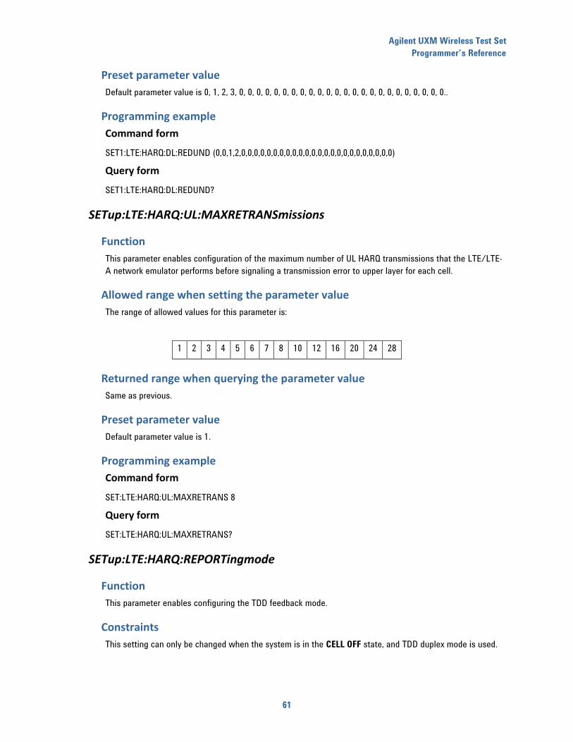
Agilent UXM Wireless Test Set
Programmer’s Reference
61
Preset parameter value
Default parameter value is 0, 1, 2, 3, 0, 0, 0, 0, 0, 0, 0, 0, 0, 0, 0, 0, 0, 0, 0, 0, 0, 0, 0, 0, 0, 0, 0, 0..
Programming example
Command form
SET1:LTE:HARQ:DL:REDUND (0,0,1,2,0,0,0,0,0,0,0,0,0,0,0,0,0,0,0,0,0,0,0,0,0,0,0,0)
Query form
SET1:LTE:HARQ:DL:REDUND?
SETup:LTE:HARQ:UL:MAXRETRANSmissions
Function
This parameter enables configuration of the maximum number of UL HARQ transmissions that the LTE/LTE-
A network emulator performs before signaling a transmission error to upper layer for each cell.
Allowed range when setting the parameter value
The range of allowed values for this parameter is:
1 2 3 4 5 6 7 8 10 12 16 20 24 28
Returned range when querying the parameter value
Same as previous.
Preset parameter value
Default parameter value is 1.
Programming example
Command form
SET:LTE:HARQ:UL:MAXRETRANS 8
Query form
SET:LTE:HARQ:UL:MAXRETRANS?
SETup:LTE:HARQ:REPORTingmode
Function
This parameter enables configuring the TDD feedback mode.
Constraints
This setting can only be changed when the system is in the CELL OFF state, and TDD duplex mode is used.
Agilent UXM Wireless Test Set
Programmer’s Reference
62
Allowed range when setting the parameter value
Two settings are available:
0, TDD feedback mode configured is Bundling.
1, TDD feedback mode configured is Multiplexing.
Returned range when querying the parameter value
Same as previous.
Preset parameter value
Default parameter value is 0 (Bundling mode).
Programming example
Command form
SET:LTE:HARQ:REPORT 1
Query form
SET:LTE:HARQ:REPORT?
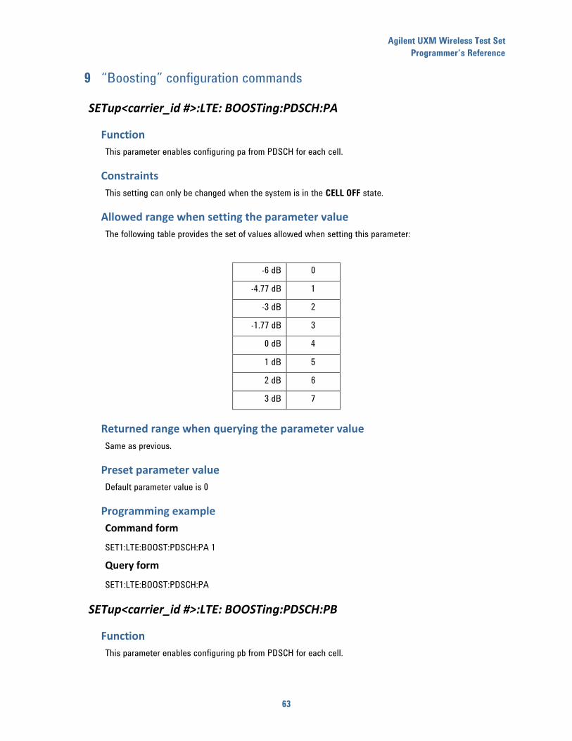
Agilent UXM Wireless Test Set
Programmer’s Reference
63
9 “Boosting” configuration commands
SETup<carrier_id #>:LTE: BOOSTing:PDSCH:PA
Function
This parameter enables configuring pa from PDSCH for each cell.
Constraints
This setting can only be changed when the system is in the CELL OFF state.
Allowed range when setting the parameter value
The following table provides the set of values allowed when setting this parameter:
-6 dB 0
-4.77 dB 1
-3 dB 2
-1.77 dB 3
0 dB 4
1 dB 5
2 dB 6
3 dB 7
Returned range when querying the parameter value
Same as previous.
Preset parameter value
Default parameter value is 0
Programming example
Command form
SET1:LTE:BOOST:PDSCH:PA 1
Query form
SET1:LTE:BOOST:PDSCH:PA
SETup<carrier_id #>:LTE: BOOSTing:PDSCH:PB
Function
This parameter enables configuring pb from PDSCH for each cell.
Agilent UXM Wireless Test Set
Programmer’s Reference
64
Constraints
This setting can only be changed when the system is in the CELL OFF state.
Allowed range when setting the parameter value
The following table provides the allowed set of values when setting this parameter:
0 1 2 3
Returned range when querying the parameter value
Same as previous.
Preset parameter value
Default p-b values is 0 in SISO or SIMO and 1 in MIMO.
Programming example
Command form
SET1:LTE:BOOST:PDSCH:PB 1
Query form
SET1:LTE:BOOST:PDSCH:PB?
SETup<carrier_id #>:LTE: BOOSTing:PSS:PA
Function
This parameter enables configuring pa from PSS for each cell.
Constraints
This setting can only be changed when the system is in the CELL OFF state.
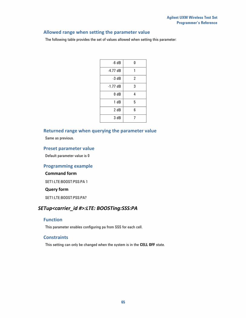
Agilent UXM Wireless Test Set
Programmer’s Reference
65
Allowed range when setting the parameter value
The following table provides the set of values allowed when setting this parameter:
-6 dB 0
-4.77 dB 1
-3 dB 2
-1.77 dB 3
0 dB 4
1 dB 5
2 dB 6
3 dB 7
Returned range when querying the parameter value
Same as previous.
Preset parameter value
Default parameter value is 0
Programming example
Command form
SET1:LTE:BOOST:PSS:PA 1
Query form
SET1:LTE:BOOST:PSS:PA?
SETup<carrier_id #>:LTE: BOOSTing:SSS:PA
Function
This parameter enables configuring pa from SSS for each cell.
Constraints
This setting can only be changed when the system is in the CELL OFF state.
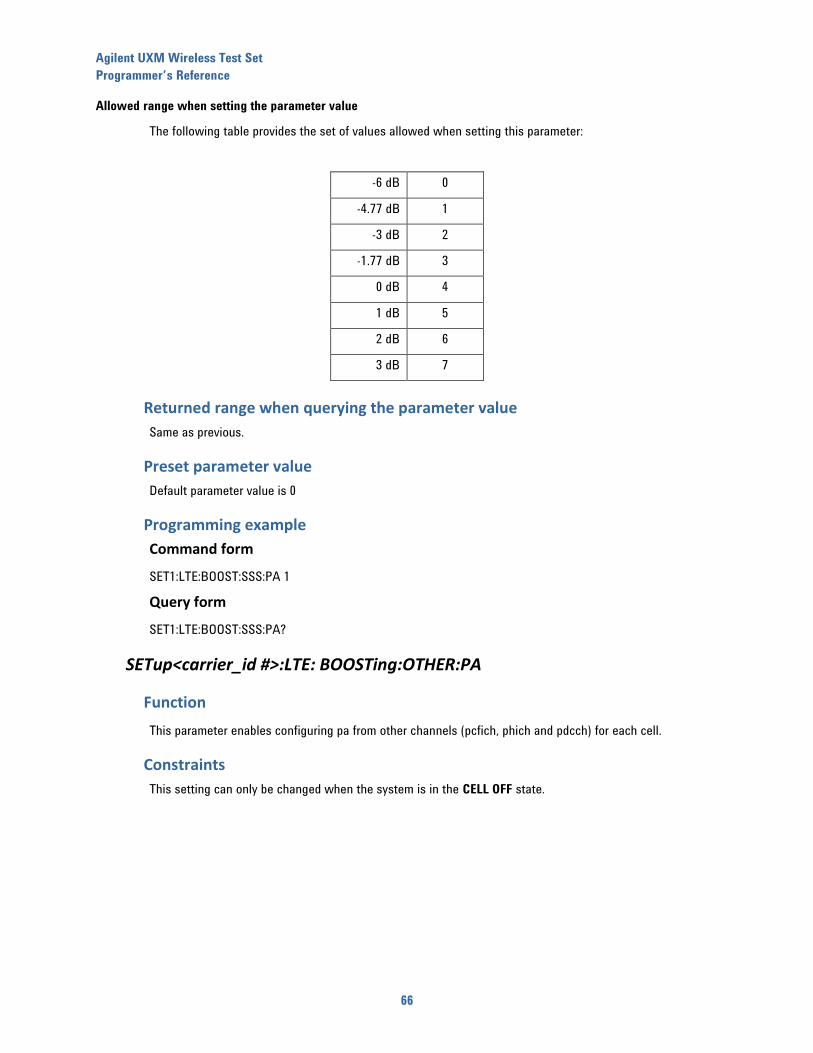
Agilent UXM Wireless Test Set
Programmer’s Reference
66
Allowed range when setting the parameter value
The following table provides the set of values allowed when setting this parameter:
-6 dB 0
-4.77 dB 1
-3 dB 2
-1.77 dB 3
0 dB 4
1 dB 5
2 dB 6
3 dB 7
Returned range when querying the parameter value
Same as previous.
Preset parameter value
Default parameter value is 0
Programming example
Command form
SET1:LTE:BOOST:SSS:PA 1
Query form
SET1:LTE:BOOST:SSS:PA?
SETup<carrier_id #>:LTE: BOOSTing:OTHER:PA
Function
This parameter enables configuring pa from other channels (pcfich, phich and pdcch) for each cell.
Constraints
This setting can only be changed when the system is in the CELL OFF state.
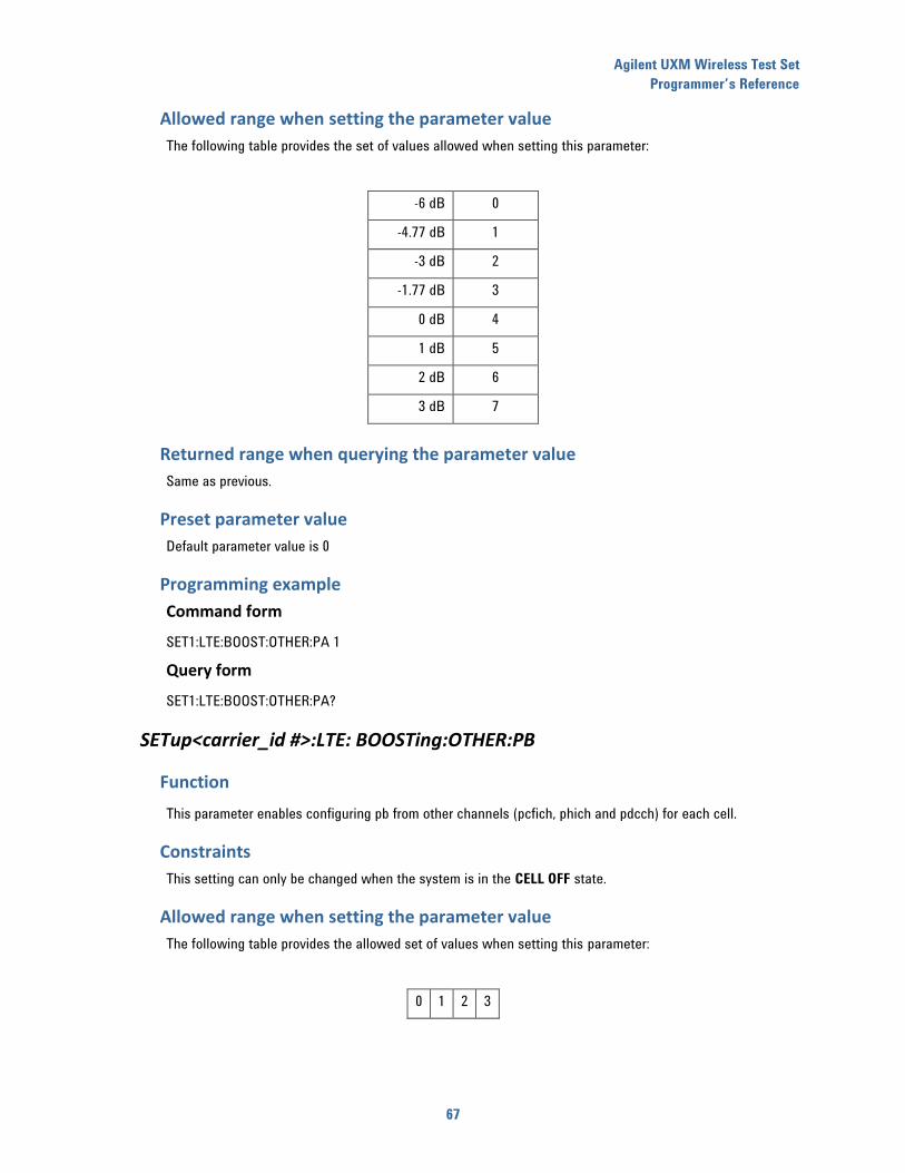
Agilent UXM Wireless Test Set
Programmer’s Reference
67
Allowed range when setting the parameter value
The following table provides the set of values allowed when setting this parameter:
-6 dB 0
-4.77 dB 1
-3 dB 2
-1.77 dB 3
0 dB 4
1 dB 5
2 dB 6
3 dB 7
Returned range when querying the parameter value
Same as previous.
Preset parameter value
Default parameter value is 0
Programming example
Command form
SET1:LTE:BOOST:OTHER:PA 1
Query form
SET1:LTE:BOOST:OTHER:PA?
SETup<carrier_id #>:LTE: BOOSTing:OTHER:PB
Function
This parameter enables configuring pb from other channels (pcfich, phich and pdcch) for each cell.
Constraints
This setting can only be changed when the system is in the CELL OFF state.
Allowed range when setting the parameter value
The following table provides the allowed set of values when setting this parameter:
0 1 2 3
Agilent UXM Wireless Test Set
Programmer’s Reference
68
Returned range when querying the parameter value
Same as previous.
Preset parameter value
Default p-b values is 0 in SISO or SIMO and 1 in MIMO.
Programming example
Command form
SET1:LTE:BOOST:OTHER:PB 1
Query form
SET1:LTE:BOOST:OTHER:PB?
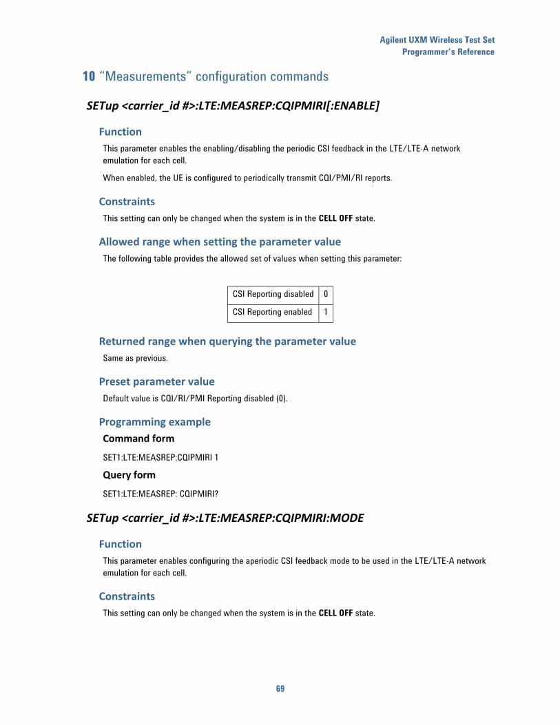
Agilent UXM Wireless Test Set
Programmer’s Reference
69
10 “Measurements” configuration commands
SETup <carrier_id #>:LTE:MEASREP:CQIPMIRI[:ENABLE]
Function
This parameter enables the enabling/disabling the periodic CSI feedback in the LTE/LTE-A network
emulation for each cell.
When enabled, the UE is configured to periodically transmit CQI/PMI/RI reports.
Constraints
This setting can only be changed when the system is in the CELL OFF state.
Allowed range when setting the parameter value
The following table provides the allowed set of values when setting this parameter:
CSI Reporting disabled 0
CSI Reporting enabled 1
Returned range when querying the parameter value
Same as previous.
Preset parameter value
Default value is CQI/RI/PMI Reporting disabled (0).
Programming example
Command form
SET1:LTE:MEASREP:CQIPMIRI 1
Query form
SET1:LTE:MEASREP: CQIPMIRI?
SETup <carrier_id #>:LTE:MEASREP:CQIPMIRI:MODE
Function
This parameter enables configuring the aperiodic CSI feedback mode to be used in the LTE/LTE-A network
emulation for each cell.
Constraints
This setting can only be changed when the system is in the CELL OFF state.
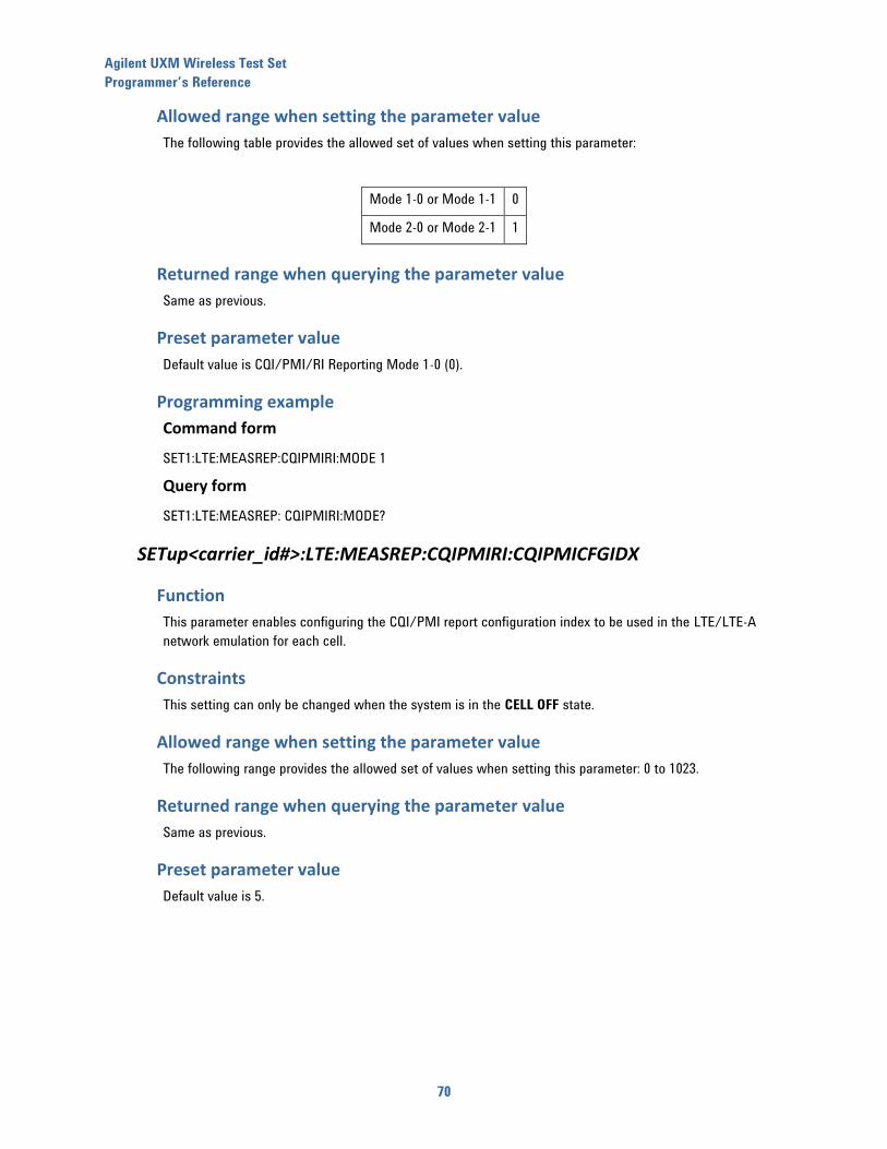
Agilent UXM Wireless Test Set
Programmer’s Reference
70
Allowed range when setting the parameter value
The following table provides the allowed set of values when setting this parameter:
Mode 1-0 or Mode 1-1 0
Mode 2-0 or Mode 2-1 1
Returned range when querying the parameter value
Same as previous.
Preset parameter value
Default value is CQI/PMI/RI Reporting Mode 1-0 (0).
Programming example
Command form
SET1:LTE:MEASREP:CQIPMIRI:MODE 1
Query form
SET1:LTE:MEASREP: CQIPMIRI:MODE?
SETup<carrier_id#>:LTE:MEASREP:CQIPMIRI:CQIPMICFGIDX
Function
This parameter enables configuring the CQI/PMI report configuration index to be used in the LTE/LTE-A
network emulation for each cell.
Constraints
This setting can only be changed when the system is in the CELL OFF state.
Allowed range when setting the parameter value
The following range provides the allowed set of values when setting this parameter: 0 to 1023.
Returned range when querying the parameter value
Same as previous.
Preset parameter value
Default value is 5.
Agilent UXM Wireless Test Set
Programmer’s Reference
71
Programming example
Command form
SET1:LTE:MEASREP:CQIPMIRI:CQIPMICFGIDX 0
Query form
SET1:LTE:MEASREP: CQIPMIRI:CQIPMICFGIDX?
SETup <carrier id #>:LTE:MEASREP:CQIPMIRI:RICFGIDX
Function
This parameter enables configuring the RI report configuration index to be used in the LTE/LTE-A network
emulation.
Constraints
This setting can only be changed when the system is in the CELL OFF state.
Allowed range when setting the parameter value
The following range provides the allowed set of values when setting this parameter: 0 to 1023.
Returned range when querying the parameter value
Same as previous.
Preset parameter value
Default value is 484.
Programming example
Command form
SET1:LTE:MEASREP:CQIPMIRI:RICFGIDX 0
Query form
SET1:LTE:MEASREP:CQIPMIRI:RICFGIDX?
SETup :LTE:MEASREP:APERIODic[:ENABLE]
Function
This parameter allows the enabling/disabling the aperiodic CSI feedback in the LTE/LTE-A network
emulation.
Constraints
This setting can only be changed in PCC when the system is in the CELL OFF state.
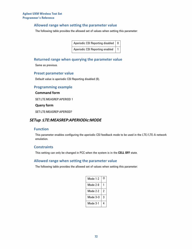
Agilent UXM Wireless Test Set
Programmer’s Reference
72
Allowed range when setting the parameter value
The following table provides the allowed set of values when setting this parameter:
Aperiodic CSI Reporting disabled 0
Aperiodic CSI Reporting enabled 1
Returned range when querying the parameter value
Same as previous.
Preset parameter value
Default value is aperiodic CSI Reporting disabled (0).
Programming example
Command form
SET:LTE:MEASREP:APERIOD 1
Query form
SET:LTE:MEASREP:APERIOD?
SETup :LTE:MEASREP:APERIODic:MODE
Function
This parameter enables configuring the aperiodic CSI feedback mode to be used in the LTE/LTE-A network
emulation.
Constraints
This setting can only be changed in PCC when the system is in the CELL OFF state.
Allowed range when setting the parameter value
The following table provides the allowed set of values when setting this parameter:
Mode 1-2 0
Mode 2-0 1
Mode 2-2 2
Mode 3-0 3
Mode 3-1 4
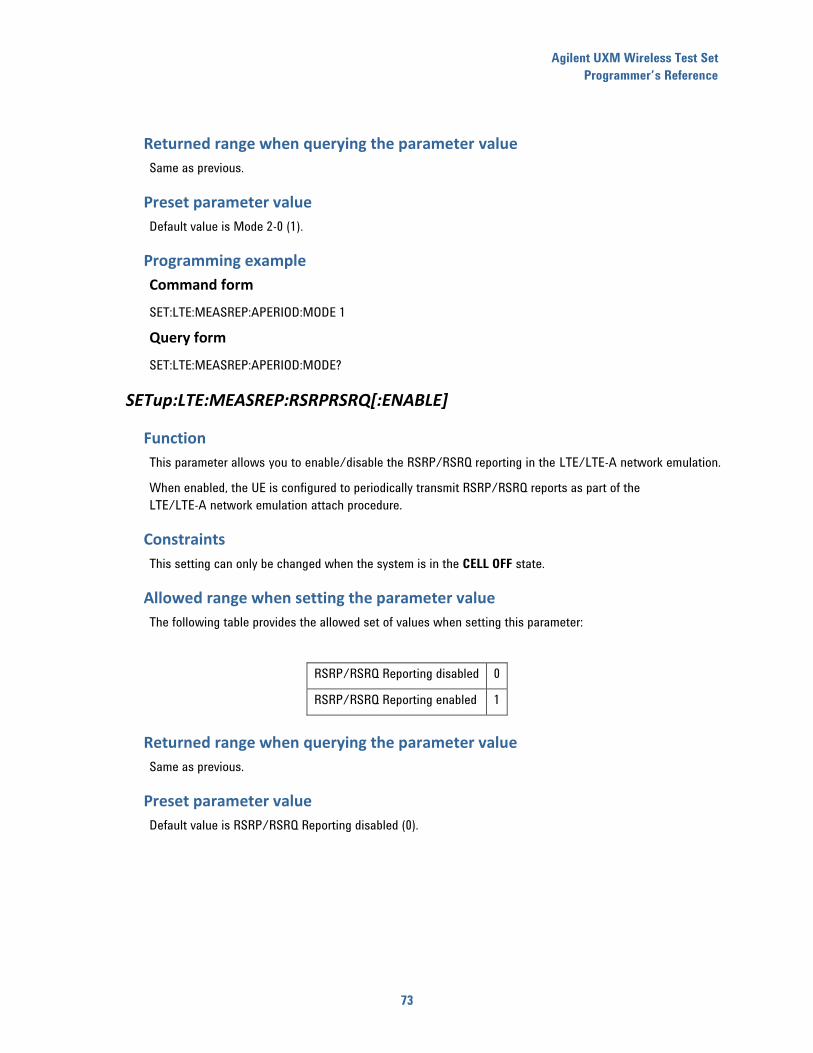
Agilent UXM Wireless Test Set
Programmer’s Reference
73
Returned range when querying the parameter value
Same as previous.
Preset parameter value
Default value is Mode 2-0 (1).
Programming example
Command form
SET:LTE:MEASREP:APERIOD:MODE 1
Query form
SET:LTE:MEASREP:APERIOD:MODE?
SETup:LTE:MEASREP:RSRPRSRQ[:ENABLE]
Function
This parameter allows you to enable/disable the RSRP/RSRQ reporting in the LTE/LTE-A network emulation.
When enabled, the UE is configured to periodically transmit RSRP/RSRQ reports as part of the
LTE/LTE-A network emulation attach procedure.
Constraints
This setting can only be changed when the system is in the CELL OFF state.
Allowed range when setting the parameter value
The following table provides the allowed set of values when setting this parameter:
RSRP/RSRQ Reporting disabled 0
RSRP/RSRQ Reporting enabled 1
Returned range when querying the parameter value
Same as previous.
Preset parameter value
Default value is RSRP/RSRQ Reporting disabled (0).
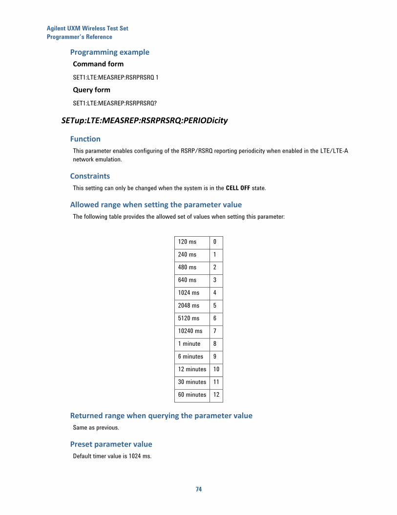
Agilent UXM Wireless Test Set
Programmer’s Reference
74
Programming example
Command form
SET1:LTE:MEASREP:RSRPRSRQ 1
Query form
SET1:LTE:MEASREP:RSRPRSRQ?
SETup:LTE:MEASREP:RSRPRSRQ:PERIODicity
Function
This parameter enables configuring of the RSRP/RSRQ reporting periodicity when enabled in the LTE/LTE-A
network emulation.
Constraints
This setting can only be changed when the system is in the CELL OFF state.
Allowed range when setting the parameter value
The following table provides the allowed set of values when setting this parameter:
120 ms 0
240 ms 1
480 ms 2
640 ms 3
1024 ms 4
2048 ms 5
5120 ms 6
10240 ms 7
1 minute 8
6 minutes 9
12 minutes 10
30 minutes 11
60 minutes 12
Returned range when querying the parameter value
Same as previous.
Preset parameter value
Default timer value is 1024 ms.

Agilent UXM Wireless Test Set
Programmer’s Reference
75
Programming example
Command form
SET1:LTE:MEASREP:RSRPRSRQ:PERIOD 3
Query form
SET1:LTE:MEASREP:RSRPRSRQ:PERIOD?
SETup:LTE:MEASREP:RSRPRSRQ:RSRPFILTERing
Function
This parameter enables configuring the L3 filtering to be applied to RSRP reports in the LTE/LTE-A network
emulation.
Constraints
This setting can only be changed when the system is in the CELL OFF state.
Allowed range when setting the parameter value
The following table provides the allowed set of values when setting this parameter:
fc0 0
fc1 1
fc2 2
fc3 3
fc4 4
fc5 5
fc6 6
fc7 7
fc8 8
fc9 9
fc11 10
fc13 11
fc15 12
fc17 13
fc19 14
Returned range when querying the parameter value
Same as previous.
Agilent UXM Wireless Test Set
Programmer’s Reference
76
Preset parameter value
Default timer value is fc4 (4).
Programming example
Command form
SET1:LTE:MEASREP:RSRPRSRQ:RSRPFILTER 3
Query form
SET1:LTE:MEASREP:RSRPRSRQ:RSRPFILTER?
SETup:LTE:MEASREP:RSRPRSRQ:RSRQFILTERing
Function
This parameter enables configuring the L3 filtering to be applied to RSRQ reports in the LTE-LTE-A network
emulation.
Constraints
This setting can only be changed when the system is in the CELL OFF state.
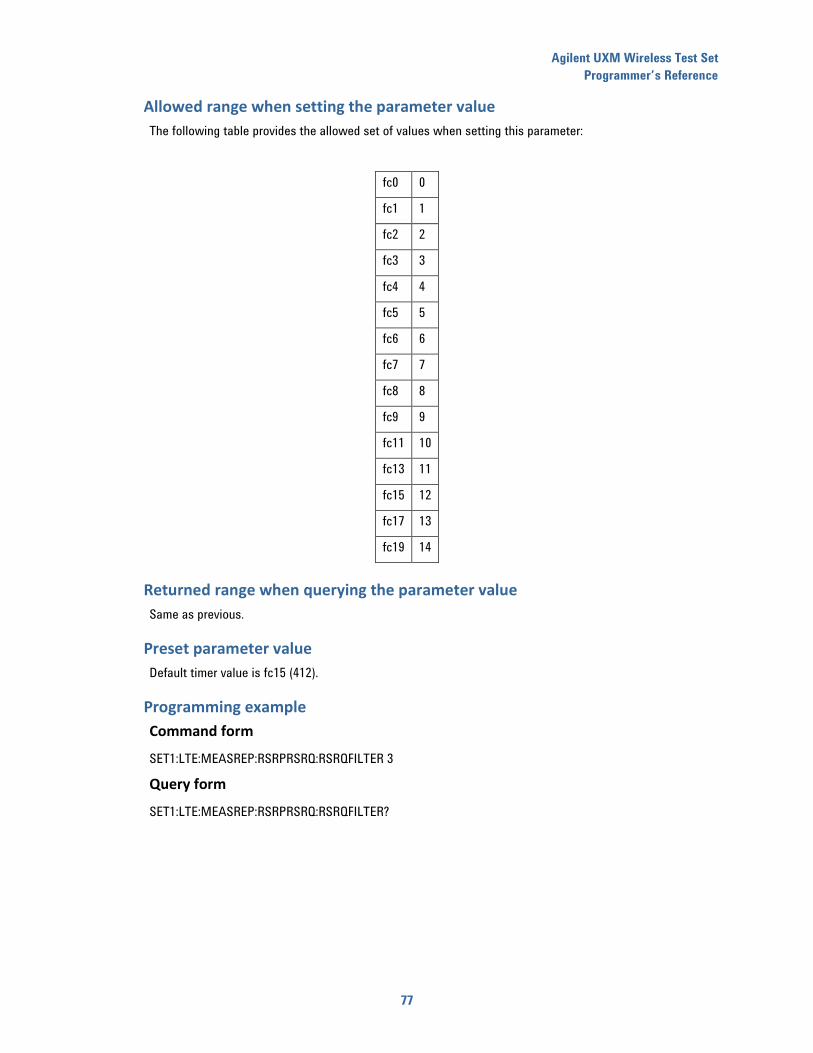
Agilent UXM Wireless Test Set
Programmer’s Reference
77
Allowed range when setting the parameter value
The following table provides the allowed set of values when setting this parameter:
fc0 0
fc1 1
fc2 2
fc3 3
fc4 4
fc5 5
fc6 6
fc7 7
fc8 8
fc9 9
fc11 10
fc13 11
fc15 12
fc17 13
fc19 14
Returned range when querying the parameter value
Same as previous.
Preset parameter value
Default timer value is fc15 (412).
Programming example
Command form
SET1:LTE:MEASREP:RSRPRSRQ:RSRQFILTER 3
Query form
SET1:LTE:MEASREP:RSRPRSRQ:RSRQFILTER?
Agilent UXM Wireless Test Set
Programmer’s Reference
78
11 “L1 Advanced” configuration commands
SETup <carrier_id #>:LTE:CNTRLREGionconfiguration:CFI
Function
This parameter enables configuring the control region size, in terms of OFDMA symbols that the control
region in each DL sub-frame are composed of, for each cell.
Allowed range when setting the parameter value
The range of allowed values are 1, 2, or 3 symbols and does not depend on the bandwidth configuration in
use.
Returned range when querying the parameter value
Same as previous.
Preset parameter value
Default parameter value is 1.
Programming example
Command form
SET1:LTE:CNTRLREG:CFI 3
Query form
SET1:LTE:CNTRLREG:CFI?
SETup<carrier_id#>:LTE:CNTRLREGionconfiguration:AGGRegationlevel:COMMonsearchspace
Function
This parameter enables configuring the aggregation level to be used in the common search space of the
control region in each DL sub-frame for each cell.
Allowed range when setting the parameter value
The set of allowed values is 4 and 8.
Returned range when querying the parameter value
Same as previous.
Preset parameter value
Default parameter value is 4.

Agilent UXM Wireless Test Set
Programmer’s Reference
79
Programming example
Command form
SET1:LTE:CNTRLREG:AGGR:COMM 4
Query form
SET1:LTE:CNTRLREG:AGGR:COMM?
SETup<carrier_id#>:LTE:CNTRLREGionconfiguration:AGGRegationlevel:UEspecificsearchspace
Function
This parameter enables configuring the aggregation level to be used in the UE-specific search space of the
control region in each DL sub-frame for each cell.
Allowed range when setting the parameter value
The set of allowed values is 1, 2, 4 and 8.
Returned range when querying the parameter value
Same as previous.
Preset parameter value
Default parameter value is 2.
Programming example
Command form
SET1:LTE:CNTRLREG:AGGR:UE 1
Query form
SET1:LTE:CNTRLREG:AGGT:UE?
SETup <carrier_id#>:LTE:PHICHconfiguration:DURation
Function
This parameter enables configuring the duration of the PHICH channel mapped to control region in each DL
sub-frame for each cell.
Constraints
This setting can only be changed when the system is in the CELL OFF state.
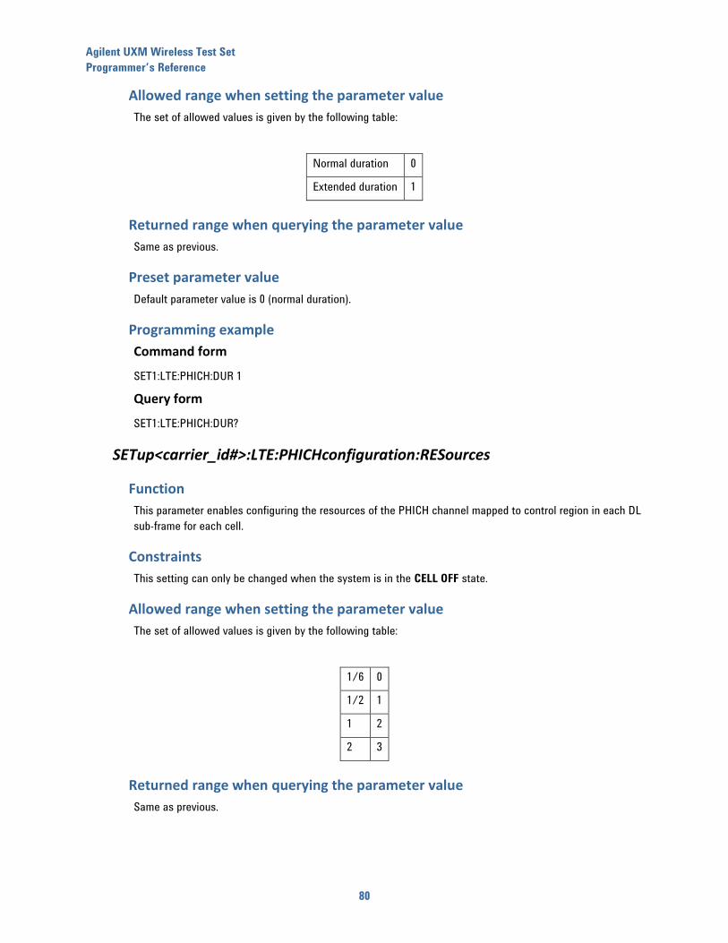
Agilent UXM Wireless Test Set
Programmer’s Reference
80
Allowed range when setting the parameter value
The set of allowed values is given by the following table:
Normal duration 0
Extended duration 1
Returned range when querying the parameter value
Same as previous.
Preset parameter value
Default parameter value is 0 (normal duration).
Programming example
Command form
SET1:LTE:PHICH:DUR 1
Query form
SET1:LTE:PHICH:DUR?
SETup<carrier_id#>:LTE:PHICHconfiguration:RESources
Function
This parameter enables configuring the resources of the PHICH channel mapped to control region in each DL
sub-frame for each cell.
Constraints
This setting can only be changed when the system is in the CELL OFF state.
Allowed range when setting the parameter value
The set of allowed values is given by the following table:
1/6 0
1/2 1
1 2
2 3
Returned range when querying the parameter value
Same as previous.
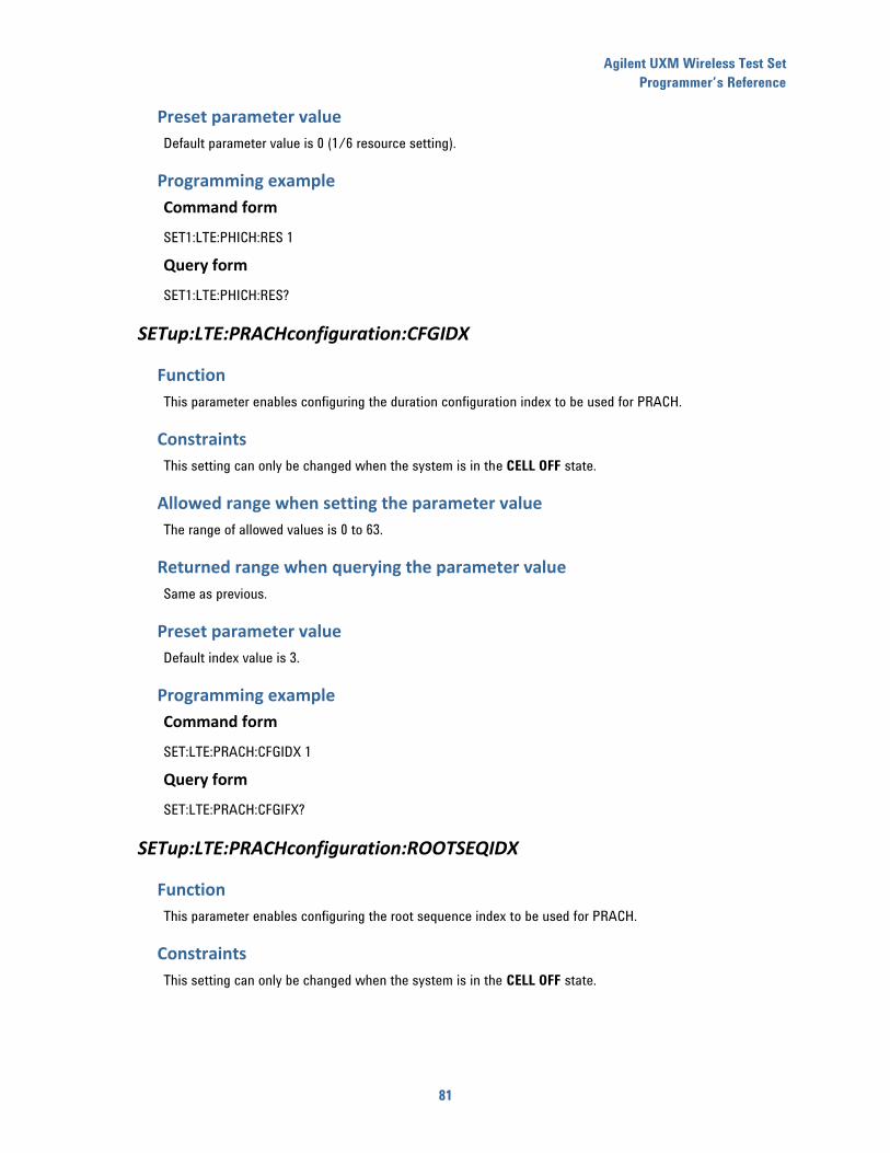
Agilent UXM Wireless Test Set
Programmer’s Reference
81
Preset parameter value
Default parameter value is 0 (1/6 resource setting).
Programming example
Command form
SET1:LTE:PHICH:RES 1
Query form
SET1:LTE:PHICH:RES?
SETup:LTE:PRACHconfiguration:CFGIDX
Function
This parameter enables configuring the duration configuration index to be used for PRACH.
Constraints
This setting can only be changed when the system is in the CELL OFF state.
Allowed range when setting the parameter value
The range of allowed values is 0 to 63.
Returned range when querying the parameter value
Same as previous.
Preset parameter value
Default index value is 3.
Programming example
Command form
SET:LTE:PRACH:CFGIDX 1
Query form
SET:LTE:PRACH:CFGIFX?
SETup:LTE:PRACHconfiguration:ROOTSEQIDX
Function
This parameter enables configuring the root sequence index to be used for PRACH.
Constraints
This setting can only be changed when the system is in the CELL OFF state.
Agilent UXM Wireless Test Set
Programmer’s Reference
82
Allowed range when setting the parameter value
The range of allowed values is 0 to 837.
Returned range when querying the parameter value
Same as previous.
Preset parameter value
Default index value is 22.
Programming example
Command form
SET:LTE:PRACH:ROOTSEQIDX 1
Query form
SET:LTE:PRACH:ROOTSEQIDX?
SETup:LTE:PRACHconfiguration:FREQOFFset
Function
This parameter enables configuring the frequency offset to be used for PRACH.
Constraints
This setting can only be changed when the system is in the CELL OFF state.
Allowed range when setting the parameter value
The range of allowed values is 0 to 94.
Returned range when querying the parameter value
Same as previous.
Preset parameter value
Default parameter value is 0.
Programming example
Command form
SET:LTE:PRACH:FREQOFF 1
Query form
SET:LTE:PRACH:FREQOFF?
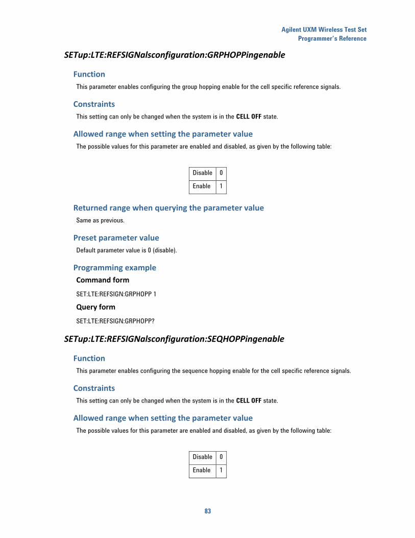
Agilent UXM Wireless Test Set
Programmer’s Reference
83
SETup:LTE:REFSIGNalsconfiguration:GRPHOPPingenable
Function
This parameter enables configuring the group hopping enable for the cell specific reference signals.
Constraints
This setting can only be changed when the system is in the CELL OFF state.
Allowed range when setting the parameter value
The possible values for this parameter are enabled and disabled, as given by the following table:
Disable 0
Enable 1
Returned range when querying the parameter value
Same as previous.
Preset parameter value
Default parameter value is 0 (disable).
Programming example
Command form
SET:LTE:REFSIGN:GRPHOPP 1
Query form
SET:LTE:REFSIGN:GRPHOPP?
SETup:LTE:REFSIGNalsconfiguration:SEQHOPPingenable
Function
This parameter enables configuring the sequence hopping enable for the cell specific reference signals.
Constraints
This setting can only be changed when the system is in the CELL OFF state.
Allowed range when setting the parameter value
The possible values for this parameter are enabled and disabled, as given by the following table:
Disable 0
Enable 1
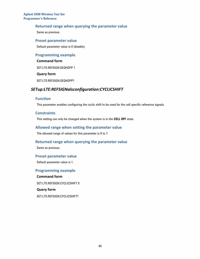
Agilent UXM Wireless Test Set
Programmer’s Reference
84
Returned range when querying the parameter value
Same as previous.
Preset parameter value
Default parameter value is 0 (disable).
Programming example
Command form
SET:LTE:REFSIGN:SEQHOPP 1
Query form
SET:LTE:REFSIGN:SEQHOPP?
SETup:LTE:REFSIGNalsconfiguration:CYCLICSHIFT
Function
This parameter enables configuring the cyclic shift to be used for the cell specific reference signals.
Constraints
This setting can only be changed when the system is in the CELL OFF state.
Allowed range when setting the parameter value
The allowed range of values for this parameter is 0 to 7.
Returned range when querying the parameter value
Same as previous.
Preset parameter value
Default parameter value is 1.
Programming example
Command form
SET:LTE:REFSIGN:CYCLICSHIFT 0
Query form
SET:LTE:REFSIGN:CYCLICSHIFT?
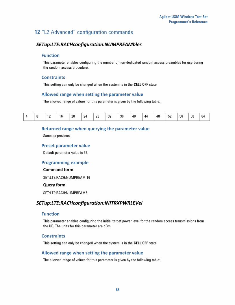
Agilent UXM Wireless Test Set
Programmer’s Reference
85
12 “L2 Advanced” configuration commands
SETup:LTE:RACHconfiguration:NUMPREAMbles
Function
This parameter enables configuring the number of non-dedicated random access preambles for use during
the random access procedure.
Constraints
This setting can only be changed when the system is in the CELL OFF state.
Allowed range when setting the parameter value
The allowed range of values for this parameter is given by the following table:
4 8 12 16 20 24 28 32 36 40 44 48 52 56 60 64
Returned range when querying the parameter value
Same as previous.
Preset parameter value
Default parameter value is 52.
Programming example
Command form
SET:LTE:RACH:NUMPREAM 16
Query form
SET:LTE:RACH:NUMPREAM?
SETup:LTE:RACHconfiguration:INITRXPWRLEVel
Function
This parameter enables configuring the initial target power level for the random access transmissions from
the UE. The units for this parameter are dBm.
Constraints
This setting can only be changed when the system is in the CELL OFF state.
Allowed range when setting the parameter value
The allowed range of values for this parameter is given by the following table:
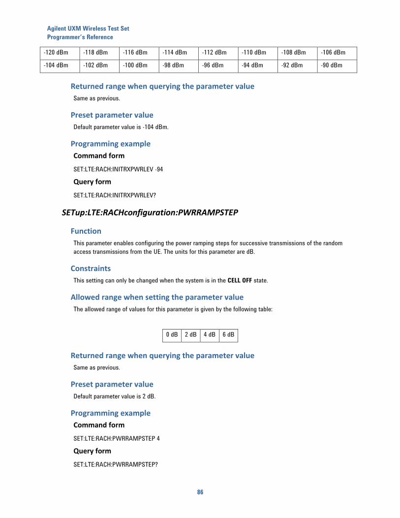
Agilent UXM Wireless Test Set
Programmer’s Reference
86
-120 dBm -118 dBm -116 dBm -114 dBm -112 dBm -110 dBm -108 dBm -106 dBm
-104 dBm -102 dBm -100 dBm -98 dBm -96 dBm -94 dBm -92 dBm -90 dBm
Returned range when querying the parameter value
Same as previous.
Preset parameter value
Default parameter value is -104 dBm.
Programming example
Command form
SET:LTE:RACH:INITRXPWRLEV -94
Query form
SET:LTE:RACH:INITRXPWRLEV?
SETup:LTE:RACHconfiguration:PWRRAMPSTEP
Function
This parameter enables configuring the power ramping steps for successive transmissions of the random
access transmissions from the UE. The units for this parameter are dB.
Constraints
This setting can only be changed when the system is in the CELL OFF state.
Allowed range when setting the parameter value
The allowed range of values for this parameter is given by the following table:
0 dB 2 dB 4 dB 6 dB
Returned range when querying the parameter value
Same as previous.
Preset parameter value
Default parameter value is 2 dB.
Programming example
Command form
SET:LTE:RACH:PWRRAMPSTEP 4
Query form
SET:LTE:RACH:PWRRAMPSTEP?
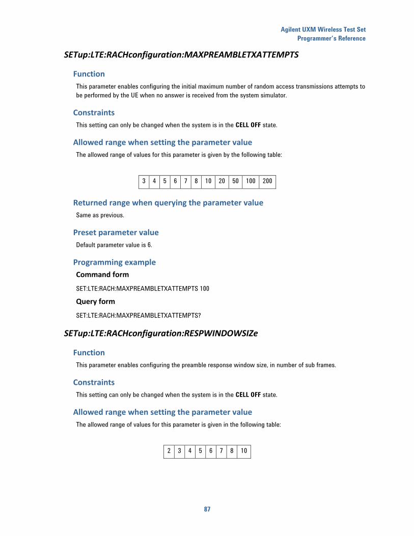
Agilent UXM Wireless Test Set
Programmer’s Reference
87
SETup:LTE:RACHconfiguration:MAXPREAMBLETXATTEMPTS
Function
This parameter enables configuring the initial maximum number of random access transmissions attempts to
be performed by the UE when no answer is received from the system simulator.
Constraints
This setting can only be changed when the system is in the CELL OFF state.
Allowed range when setting the parameter value
The allowed range of values for this parameter is given by the following table:
3 4 5 6 7 8 10 20 50 100 200
Returned range when querying the parameter value
Same as previous.
Preset parameter value
Default parameter value is 6.
Programming example
Command form
SET:LTE:RACH:MAXPREAMBLETXATTEMPTS 100
Query form
SET:LTE:RACH:MAXPREAMBLETXATTEMPTS?
SETup:LTE:RACHconfiguration:RESPWINDOWSIZe
Function
This parameter enables configuring the preamble response window size, in number of sub frames.
Constraints
This setting can only be changed when the system is in the CELL OFF state.
Allowed range when setting the parameter value
The allowed range of values for this parameter is given in the following table:
2 3 4 5 6 7 8 10

Agilent UXM Wireless Test Set
Programmer’s Reference
88
Returned range when querying the parameter value
Same as previous.
Preset parameter value
Default parameter values is 10 sub frames.
Programming example
Command form
SET:LTE:RACH:RESPWINDOWSIZ 5
Query form
SET:LTE:RACH:RESPWINDOWSIZ?
SETup:LTE:RACHconfiguration:CONTENTIONRESOLTIMer
Function
This parameter enables configuring the random access procedure contention resolution timer vale, in
number of sub frames.
Constraints
This setting can only be changed when the system is in the CELL OFF state.
Allowed range when setting the parameter value
The allowed range of values for this parameter is given in the following table:
8 16 24 32 40 48 56 64
Returned range when querying the parameter value
Same as previous.
Preset parameter value
Default parameter value is 48 sub frames.
Programming example
Command form
SET:LTE:RACH:CONTENTIONRESOLTIM 24
Query form
SET:LTE:RACH:CONTENTIONRESOLTIM?
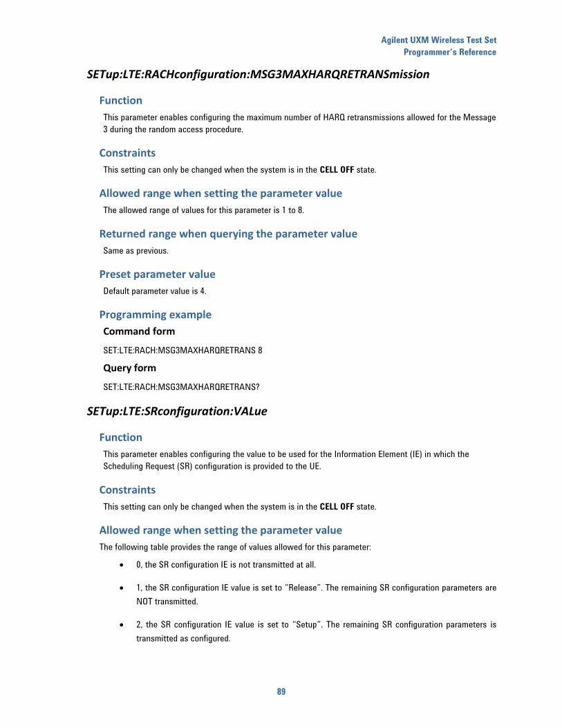
Agilent UXM Wireless Test Set
Programmer’s Reference
89
SETup:LTE:RACHconfiguration:MSG3MAXHARQRETRANSmission
Function
This parameter enables configuring the maximum number of HARQ retransmissions allowed for the Message
3 during the random access procedure.
Constraints
This setting can only be changed when the system is in the CELL OFF state.
Allowed range when setting the parameter value
The allowed range of values for this parameter is 1 to 8.
Returned range when querying the parameter value
Same as previous.
Preset parameter value
Default parameter value is 4.
Programming example
Command form
SET:LTE:RACH:MSG3MAXHARQRETRANS 8
Query form
SET:LTE:RACH:MSG3MAXHARQRETRANS?
SETup:LTE:SRconfiguration:VALue
Function
This parameter enables configuring the value to be used for the Information Element (IE) in which the
Scheduling Request (SR) configuration is provided to the UE.
Constraints
This setting can only be changed when the system is in the CELL OFF state.
Allowed range when setting the parameter value
The following table provides the range of values allowed for this parameter:
0, the SR configuration IE is not transmitted at all.
1, the SR configuration IE value is set to “Release”. The remaining SR configuration parameters are
NOT transmitted.
2, the SR configuration IE value is set to “Setup”. The remaining SR configuration parameters is
transmitted as configured.
Agilent UXM Wireless Test Set
Programmer’s Reference
90
Returned range when querying the parameter value
Same as previous.
Preset parameter value
Default parameter value is 2 (Setup).
Programming example
Command form
SET:LTE:SR:VAL 2
Query form
SET:LTE:SR:VAL?
SETup:LTE:SRconfiguration:PUCCHRESIDX
Function
This parameter enables configuring the PUCCH resource that the UE uses when transmitting scheduling
requests to the System Simulator (SS).
Constraints
This setting can only be changed when the system is in the CELL OFF state.
Allowed range when setting the parameter value
The allowed range for this parameter depends on the actual system bandwidth configured in the emulated
LTE cell. The maximum range is 0 to 2047.
Returned range when querying the parameter value
Same as previous.
Preset parameter value
Default parameter value is 39.
Programming example
Command form
SET:LTE:SR:PUCCHRESIDX 5
Query form
SET:LTE:SR:PUCCHRESIDX?
SETup:LTE:SRconfiguration:CFGIDX
Function
This parameter enables configuring the PUCCH configuration index to be used by the UE transmitting SR to
the system simulator.

Agilent UXM Wireless Test Set
Programmer’s Reference
91
Constraints
This setting can only be changed when the system is in the CELL OFF state.
Allowed range when setting the parameter value
The allowed range for this parameter is 0 to 155.
Returned range when querying the parameter value
Same as previous.
Preset parameter value
Default parameter value is 10.
Programming example
Command form
SET:LTE:SR:CFGIDX 5
Query form
SET:LTE:SR:CFGIDX?
SETup:LTE:SRconfiguration:DSRTXMAX
Function
This parameter enables configuring the maximum number of SR transmissions the UE is allowed to perform
before switching to a random access procedure, in case the system simulator does not answer to the
requests.
Constraints
This setting can only be changed when the system is in the CELL OFF state.
Allowed range when setting the parameter value
The allowed range for this parameter is given in the following table:
4 8 16 32 64
Returned range when querying the parameter value
Same as previous.
Preset parameter value
Default parameter value is 4.
Agilent UXM Wireless Test Set
Programmer’s Reference
92
Programming example
Command form
SET:LTE:SR:DSRTXMAX 32
Query form
SET:LTE:SR:DSRTXMAX?
SETup:LTE:CRNTI
Function
This parameter enables configuring C-RNTI value to be used for the PDSCH allocations signaled to the UE by
the system simulator.
Constraints
This setting can only be changed when the system is in the CELL OFF state.
Allowed range when setting the parameter value
The allowed range of values for this parameter is 0x0001 to 0xFFF3.
Returned range when querying the parameter value
Same as previous.
Preset parameter value
Default parameter value is 1.
Programming example
Command form
SET:LTE:CRNTI 5
Query form
SET:LTE:CRNTI?
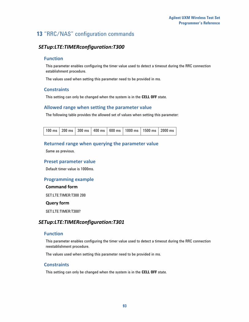
Agilent UXM Wireless Test Set
Programmer’s Reference
93
13 “RRC/NAS” configuration commands
SETup:LTE:TIMERconfiguration:T300
Function
This parameter enables configuring the timer value used to detect a timeout during the RRC connection
establishment procedure.
The values used when setting this parameter need to be provided in ms.
Constraints
This setting can only be changed when the system is in the CELL OFF state.
Allowed range when setting the parameter value
The following table provides the allowed set of values when setting this parameter:
100 ms 200 ms 300 ms 400 ms 600 ms 1000 ms 1500 ms 2000 ms
Returned range when querying the parameter value
Same as previous.
Preset parameter value
Default timer value is 1000ms.
Programming example
Command form
SET:LTE:TIMER:T300 200
Query form
SET:LTE:TIMER:T300?
SETup:LTE:TIMERconfiguration:T301
Function
This parameter enables configuring the timer value used to detect a timeout during the RRC connection
reestablishment procedure.
The values used when setting this parameter need to be provided in ms.
Constraints
This setting can only be changed when the system is in the CELL OFF state.
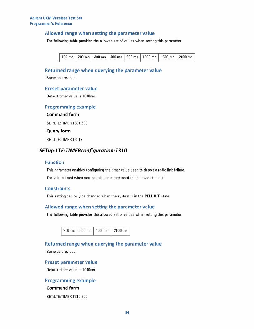
Agilent UXM Wireless Test Set
Programmer’s Reference
94
Allowed range when setting the parameter value
The following table provides the allowed set of values when setting this parameter:
100 ms 200 ms 300 ms 400 ms 600 ms 1000 ms 1500 ms 2000 ms
Returned range when querying the parameter value
Same as previous.
Preset parameter value
Default timer value is 1000ms.
Programming example
Command form
SET:LTE:TIMER:T301 300
Query form
SET:LTE:TIMER:T301?
SETup:LTE:TIMERconfiguration:T310
Function
This parameter enables configuring the timer value used to detect a radio link failure.
The values used when setting this parameter need to be provided in ms.
Constraints
This setting can only be changed when the system is in the CELL OFF state.
Allowed range when setting the parameter value
The following table provides the allowed set of values when setting this parameter:
200 ms 500 ms 1000 ms 2000 ms
Returned range when querying the parameter value
Same as previous.
Preset parameter value
Default timer value is 1000ms.
Programming example
Command form
SET:LTE:TIMER:T310 200
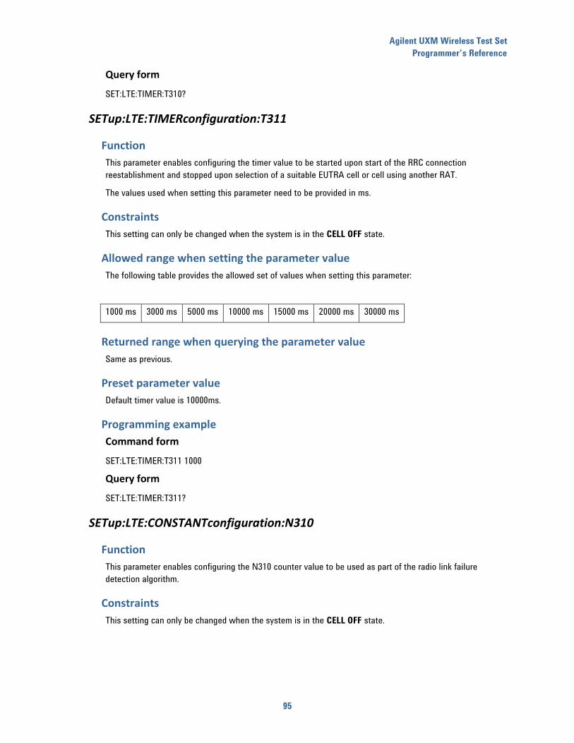
Agilent UXM Wireless Test Set
Programmer’s Reference
95
Query form
SET:LTE:TIMER:T310?
SETup:LTE:TIMERconfiguration:T311
Function
This parameter enables configuring the timer value to be started upon start of the RRC connection
reestablishment and stopped upon selection of a suitable EUTRA cell or cell using another RAT.
The values used when setting this parameter need to be provided in ms.
Constraints
This setting can only be changed when the system is in the CELL OFF state.
Allowed range when setting the parameter value
The following table provides the allowed set of values when setting this parameter:
1000 ms 3000 ms 5000 ms 10000 ms 15000 ms 20000 ms 30000 ms
Returned range when querying the parameter value
Same as previous.
Preset parameter value
Default timer value is 10000ms.
Programming example
Command form
SET:LTE:TIMER:T311 1000
Query form
SET:LTE:TIMER:T311?
SETup:LTE:CONSTANTconfiguration:N310
Function
This parameter enables configuring the N310 counter value to be used as part of the radio link failure
detection algorithm.
Constraints
This setting can only be changed when the system is in the CELL OFF state.
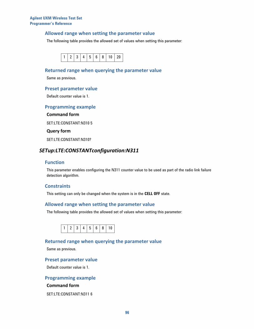
Agilent UXM Wireless Test Set
Programmer’s Reference
96
Allowed range when setting the parameter value
The following table provides the allowed set of values when setting this parameter:
1 2 3 4 5 6 8 10 20
Returned range when querying the parameter value
Same as previous.
Preset parameter value
Default counter value is 1.
Programming example
Command form
SET:LTE:CONSTANT:N310 5
Query form
SET:LTE:CONSTANT:N310?
SETup:LTE:CONSTANTconfiguration:N311
Function
This parameter enables configuring the N311 counter value to be used as part of the radio link failure
detection algorithm.
Constraints
This setting can only be changed when the system is in the CELL OFF state.
Allowed range when setting the parameter value
The following table provides the allowed set of values when setting this parameter:
1 2 3 4 5 6 8 10
Returned range when querying the parameter value
Same as previous.
Preset parameter value
Default counter value is 1.
Programming example
Command form
SET:LTE:CONSTANT:N311 6
Agilent UXM Wireless Test Set
Programmer’s Reference
97
Query form
SET:LTE:CONSTANT:N311?
SETup:LTE:IP:APN
Function
Set/queries the current value for the access point name (APN) parameter to be transmitted to the UE during
the registration procedure.
Constraints
This setting can only be changed when the system is in the CELL OFF state.
Allowed range when setting the parameter value
The access point name parameter is provided as an ASCII string, with a minimum length of 1 character and a
maximum length of 100 characters.
Returned range when querying the parameter value
Same as previous.
Preset parameter value
Default setting for this parameter is: Agilent.
Programming example
Command form
SET:LTE:IP:APN “Test Network”
Query form
SET:LTE:IP:APN?
SETup:LTE:IP:V4ADDRess
Function
Set/queries the current value for the IPv4 protocol address to be used when assigning an IPv4 address to
the UE during the registration procedure.
Note that this happens both when the TA/LA is configured to assign an IPv4 address during registration,
and when it is configured to assign both an IPv4 and IPv6 addresses.
Constraints
This setting can only be changed when the system is in the CELL OFF state.
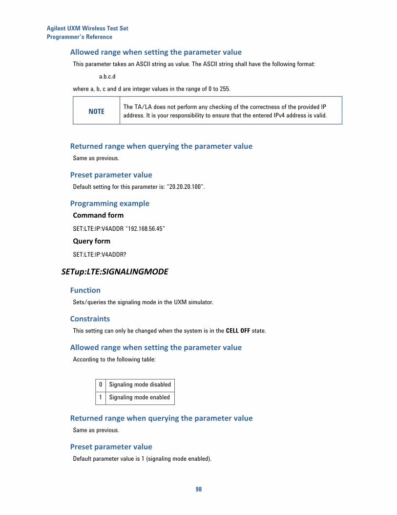
Agilent UXM Wireless Test Set
Programmer’s Reference
98
Allowed range when setting the parameter value
This parameter takes an ASCII string as value. The ASCII string shall have the following format:
a.b.c.d
where a, b, c and d are integer values in the range of 0 to 255.
NOTE
The TA/LA does not perform any checking of the correctness of the provided IP
address. It is your responsibility to ensure that the entered IPv4 address is valid.
Returned range when querying the parameter value
Same as previous.
Preset parameter value
Default setting for this parameter is: “20.20.20.100”.
Programming example
Command form
SET:LTE:IP:V4ADDR “192.168.56.45”
Query form
SET:LTE:IP:V4ADDR?
SETup:LTE:SIGNALINGMODE
Function
Sets/queries the signaling mode in the UXM simulator.
Constraints
This setting can only be changed when the system is in the CELL OFF state.
Allowed range when setting the parameter value
According to the following table:
0 Signaling mode disabled
1 Signaling mode enabled
Returned range when querying the parameter value
Same as previous.
Preset parameter value
Default parameter value is 1 (signaling mode enabled).
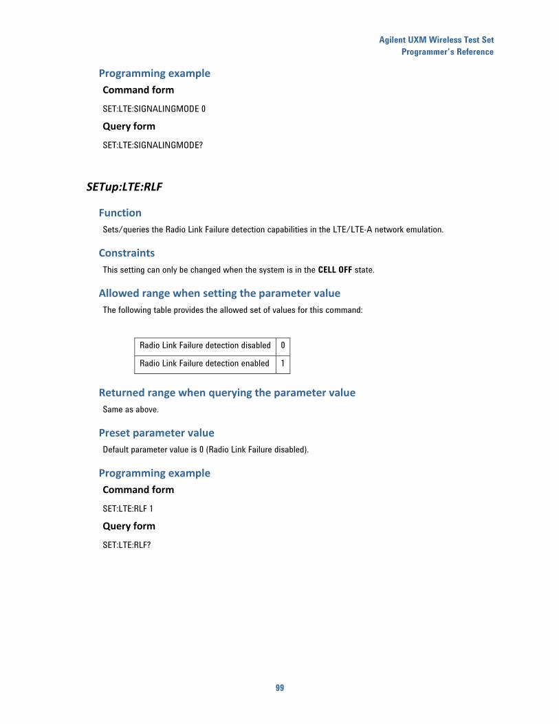
Agilent UXM Wireless Test Set
Programmer’s Reference
99
Programming example
Command form
SET:LTE:SIGNALINGMODE 0
Query form
SET:LTE:SIGNALINGMODE?
SETup:LTE:RLF
Function
Sets/queries the Radio Link Failure detection capabilities in the LTE/LTE-A network emulation.
Constraints
This setting can only be changed when the system is in the CELL OFF state.
Allowed range when setting the parameter value
The following table provides the allowed set of values for this command:
Radio Link Failure detection disabled 0
Radio Link Failure detection enabled 1
Returned range when querying the parameter value
Same as above.
Preset parameter value
Default parameter value is 0 (Radio Link Failure disabled).
Programming example
Command form
SET:LTE:RLF 1
Query form
SET:LTE:RLF?
Agilent UXM Wireless Test Set
Programmer’s Reference
100
14 “Security” configuration commands
SETup:LTE:SECURITYconfiguration:STATe
Function
Sets/queries the current state of the security procedures performed during UE registration to the UXM.
When in disabled state, the system simulator skips the integrity/security related signaling procedures
normally performed during UE registration.
When in enabled state, the system simulator executes the integrity/security related procedures as part of
the UE network registration procedures.
Constraints
This setting can only be changed when the system is in the CELL OFF state.
Allowed range when setting the parameter value
0, indicating the integrity/security procedures are disabled.
1, indicating the integrity/security procedures are enabled.
Returned range when querying the parameter value
Same as previous.
Preset parameter value
Default setting for this parameter is enabled (1).
Programming example
Command form
SET:LTE:SECURITY:STATE 1
Query form
SET:LTE:SECURITY:STATE?
SETup:LTE:SECURITYconfiguration:AUTHKey
Function
Set/queries the current value of the authentication key to be used during the registration process.
Constraints
This setting can only be changed when the system is in the CELL OFF state.
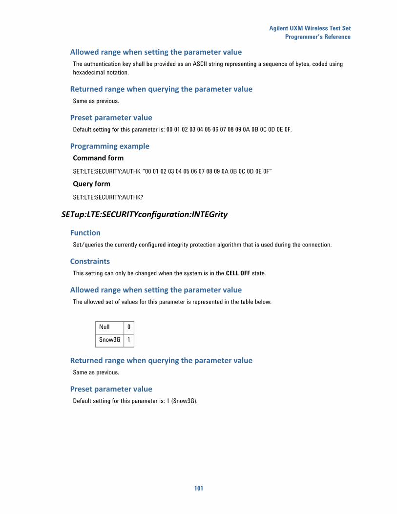
Agilent UXM Wireless Test Set
Programmer’s Reference
101
Allowed range when setting the parameter value
The authentication key shall be provided as an ASCII string representing a sequence of bytes, coded using
hexadecimal notation.
Returned range when querying the parameter value
Same as previous.
Preset parameter value
Default setting for this parameter is: 00 01 02 03 04 05 06 07 08 09 0A 0B 0C 0D 0E 0F.
Programming example
Command form
SET:LTE:SECURITY:AUTHK “00 01 02 03 04 05 06 07 08 09 0A 0B 0C 0D 0E 0F”
Query form
SET:LTE:SECURITY:AUTHK?
SETup:LTE:SECURITYconfiguration:INTEGrity
Function
Set/queries the currently configured integrity protection algorithm that is used during the connection.
Constraints
This setting can only be changed when the system is in the CELL OFF state.
Allowed range when setting the parameter value
The allowed set of values for this parameter is represented in the table below:
Null 0
Snow3G 1
Returned range when querying the parameter value
Same as previous.
Preset parameter value
Default setting for this parameter is: 1 (Snow3G).
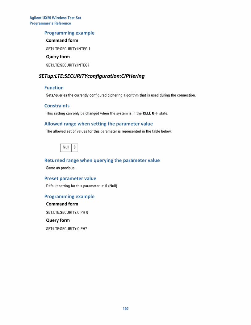
Agilent UXM Wireless Test Set
Programmer’s Reference
102
Programming example
Command form
SET:LTE:SECURITY:INTEG 1
Query form
SET:LTE:SECURITY:INTEG?
SETup:LTE:SECURITYconfiguration:CIPHering
Function
Sets/queries the currently configured ciphering algorithm that is used during the connection.
Constraints
This setting can only be changed when the system is in the CELL OFF state.
Allowed range when setting the parameter value
The allowed set of values for this parameter is represented in the table below:
Null 0
Returned range when querying the parameter value
Same as previous.
Preset parameter value
Default setting for this parameter is: 0 (Null).
Programming example
Command form
SET:LTE:SECURITY:CIPH 0
Query form
SET:LTE:SECURITY:CIPH?

Agilent UXM Wireless Test Set
Programmer’s Reference
103
15 “DRB” configuration commands
SETup:LTE:DRB:RLCMode
Function
This command enables setting/querying the RLC mode value.
Constraints
This setting can only be changed when the system is in the CELL OFF state.
Allowed range when setting the parameter value
The allowed set of values for this parameter is represented in the table below:
AM 0
UM 1
Returned range when querying the parameter value
Same as previous.
Preset parameter value
Default setting for this parameter is UM (1S).
Programming example
Command form
SET:LTE:DRB:RLCM 1
Query form
SET:LTE:DRB:RLCM?
SETup:LTE:DRB:ID
Function
This command enables setting/querying the DRB identity value.
Constraints
This setting can only be changed when the system is in the CELL OFF state.
Allowed range when setting the parameter value
The allowed range of values when setting this parameter is 1 to 32.
Returned range when querying the parameter value
Same as previous.
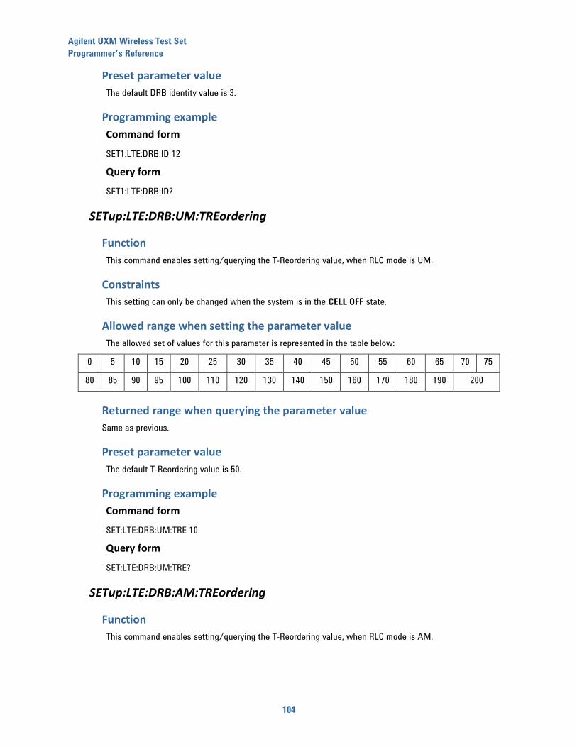
Agilent UXM Wireless Test Set
Programmer’s Reference
104
Preset parameter value
The default DRB identity value is 3.
Programming example
Command form
SET1:LTE:DRB:ID 12
Query form
SET1:LTE:DRB:ID?
SETup:LTE:DRB:UM:TREordering
Function
This command enables setting/querying the T-Reordering value, when RLC mode is UM.
Constraints
This setting can only be changed when the system is in the CELL OFF state.
Allowed range when setting the parameter value
The allowed set of values for this parameter is represented in the table below:
0 5 10 15 20 25 30 35 40 45 50 55 60 65 70 75
80 85 90 95 100 110 120 130 140 150 160 170 180 190 200
Returned range when querying the parameter value
Same as previous.
Preset parameter value
The default T-Reordering value is 50.
Programming example
Command form
SET:LTE:DRB:UM:TRE 10
Query form
SET:LTE:DRB:UM:TRE?
SETup:LTE:DRB:AM:TREordering
Function
This command enables setting/querying the T-Reordering value, when RLC mode is AM.
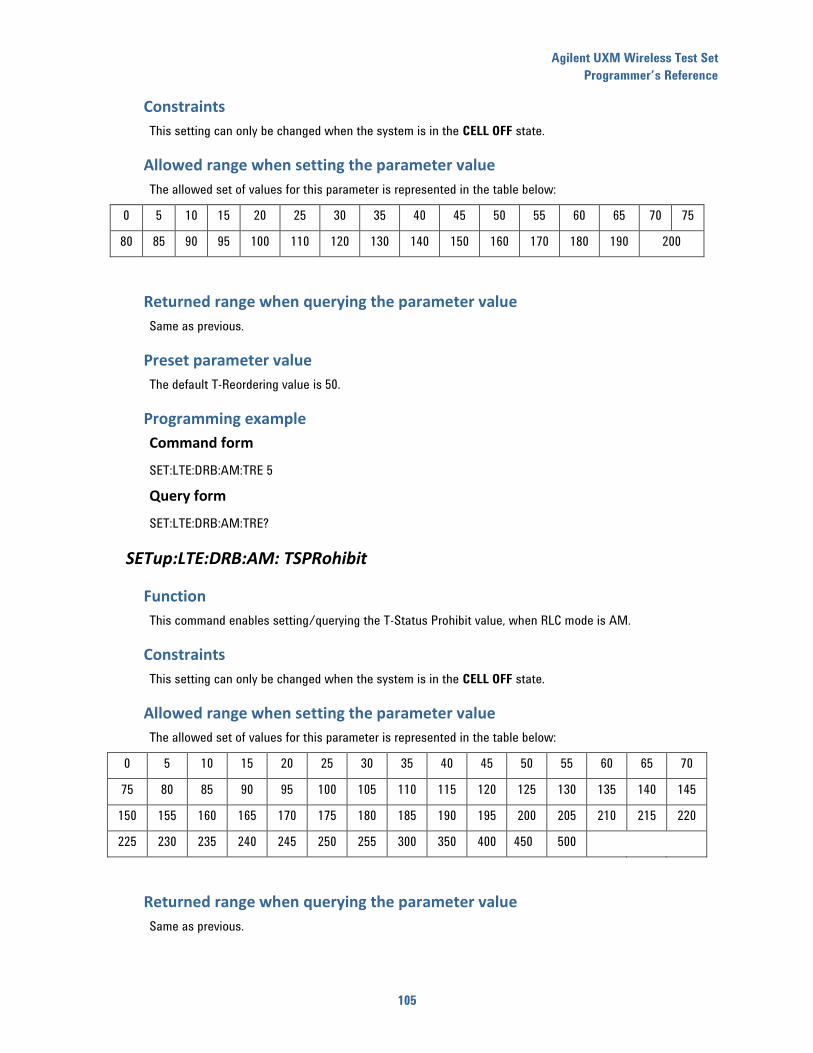
Agilent UXM Wireless Test Set
Programmer’s Reference
105
Constraints
This setting can only be changed when the system is in the CELL OFF state.
Allowed range when setting the parameter value
The allowed set of values for this parameter is represented in the table below:
0 5 10 15 20 25 30 35 40 45 50 55 60 65 70 75
80 85 90 95 100 110 120 130 140 150 160 170 180 190 200
Returned range when querying the parameter value
Same as previous.
Preset parameter value
The default T-Reordering value is 50.
Programming example
Command form
SET:LTE:DRB:AM:TRE 5
Query form
SET:LTE:DRB:AM:TRE?
SETup:LTE:DRB:AM: TSPRohibit
Function
This command enables setting/querying the T-Status Prohibit value, when RLC mode is AM.
Constraints
This setting can only be changed when the system is in the CELL OFF state.
Allowed range when setting the parameter value
The allowed set of values for this parameter is represented in the table below:
0 5 10 15 20 25 30 35 40 45 50 55 60 65 70
75 80 85 90 95 100 105 110 115 120 125 130 135 140 145
150 155 160 165 170 175 180 185 190 195 200 205 210 215 220
225 230 235 240 245 250 255 300 350 400 450 500
Returned range when querying the parameter value
Same as previous.
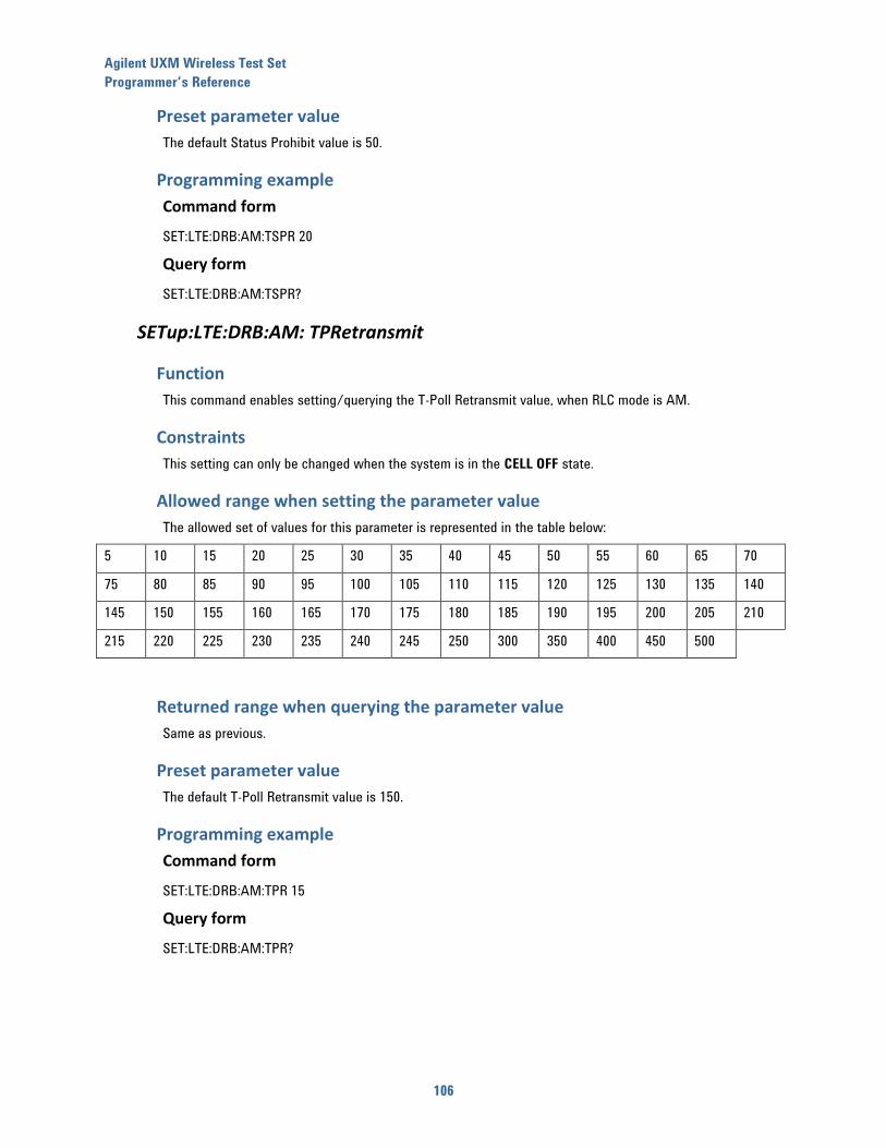
Agilent UXM Wireless Test Set
Programmer’s Reference
106
Preset parameter value
The default Status Prohibit value is 50.
Programming example
Command form
SET:LTE:DRB:AM:TSPR 20
Query form
SET:LTE:DRB:AM:TSPR?
SETup:LTE:DRB:AM: TPRetransmit
Function
This command enables setting/querying the T-Poll Retransmit value, when RLC mode is AM.
Constraints
This setting can only be changed when the system is in the CELL OFF state.
Allowed range when setting the parameter value
The allowed set of values for this parameter is represented in the table below:
5 10 15 20 25 30 35 40 45 50 55 60 65 70
75 80 85 90 95 100 105 110 115 120 125 130 135 140
145 150 155 160 165 170 175 180 185 190 195 200 205 210
215 220 225 230 235 240 245 250 300 350 400 450 500
Returned range when querying the parameter value
Same as previous.
Preset parameter value
The default T-Poll Retransmit value is 150.
Programming example
Command form
SET:LTE:DRB:AM:TPR 15
Query form
SET:LTE:DRB:AM:TPR?
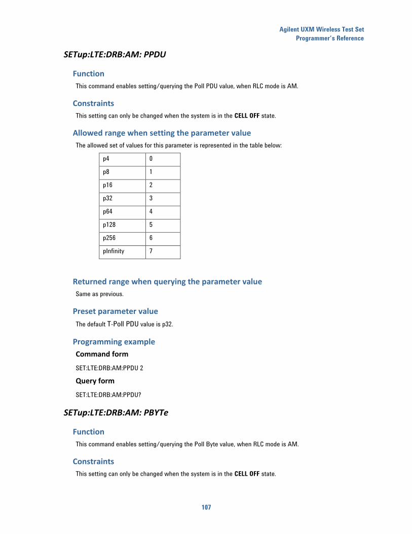
Agilent UXM Wireless Test Set
Programmer’s Reference
107
SETup:LTE:DRB:AM: PPDU
Function
This command enables setting/querying the Poll PDU value, when RLC mode is AM.
Constraints
This setting can only be changed when the system is in the CELL OFF state.
Allowed range when setting the parameter value
The allowed set of values for this parameter is represented in the table below:
p4 0
p8 1
p16 2
p32 3
p64 4
p128 5
p256 6
pInfinity 7
Returned range when querying the parameter value
Same as previous.
Preset parameter value
The default T-Poll PDU value is p32.
Programming example
Command form
SET:LTE:DRB:AM:PPDU 2
Query form
SET:LTE:DRB:AM:PPDU?
SETup:LTE:DRB:AM: PBYTe
Function
This command enables setting/querying the Poll Byte value, when RLC mode is AM.
Constraints
This setting can only be changed when the system is in the CELL OFF state.
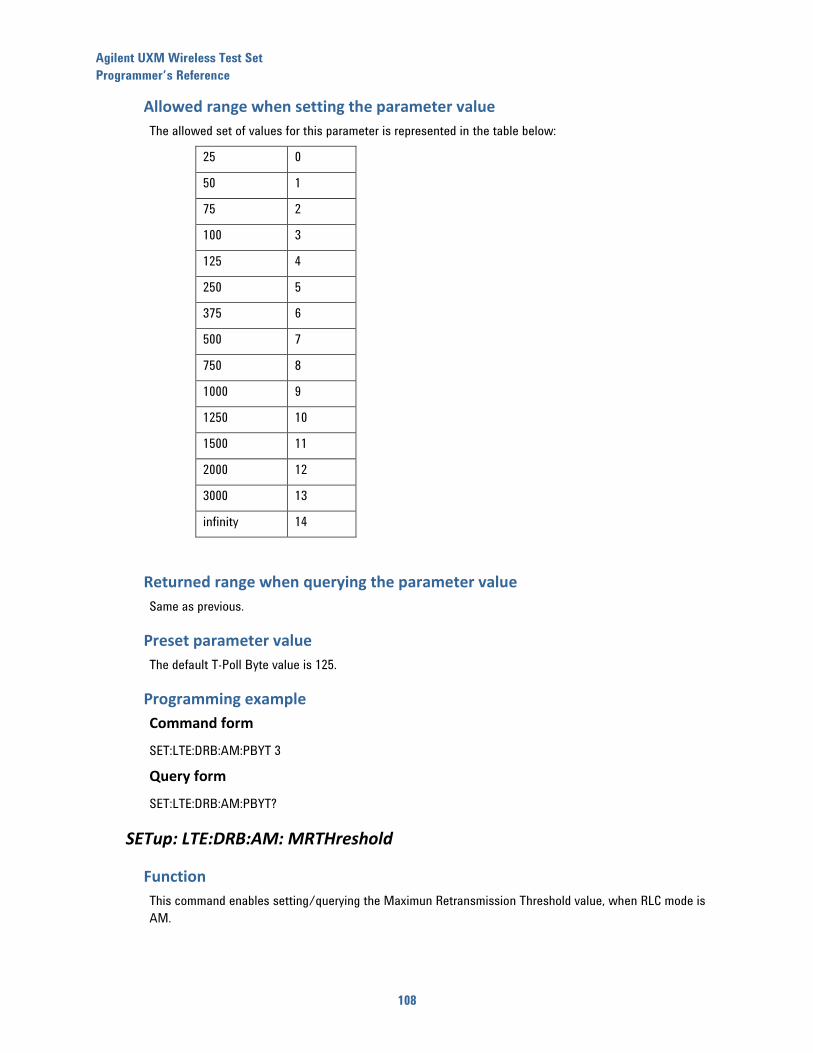
Agilent UXM Wireless Test Set
Programmer’s Reference
108
Allowed range when setting the parameter value
The allowed set of values for this parameter is represented in the table below:
25 0
50 1
75 2
100 3
125 4
250 5
375 6
500 7
750 8
1000 9
1250 10
1500 11
2000 12
3000 13
infinity 14
Returned range when querying the parameter value
Same as previous.
Preset parameter value
The default T-Poll Byte value is 125.
Programming example
Command form
SET:LTE:DRB:AM:PBYT 3
Query form
SET:LTE:DRB:AM:PBYT?
SETup: LTE:DRB:AM: MRTHreshold
Function
This command enables setting/querying the Maximun Retransmission Threshold value, when RLC mode is
AM.
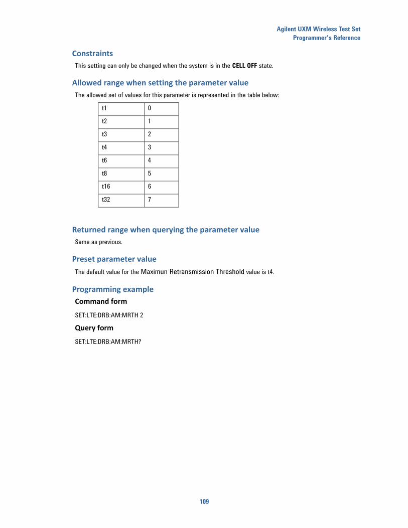
Agilent UXM Wireless Test Set
Programmer’s Reference
109
Constraints
This setting can only be changed when the system is in the CELL OFF state.
Allowed range when setting the parameter value
The allowed set of values for this parameter is represented in the table below:
t1 0
t2 1
t3 2
t4 3
t6 4
t8 5
t16 6
t32 7
Returned range when querying the parameter value
Same as previous.
Preset parameter value
The default value for the Maximun Retransmission Threshold value is t4.
Programming example
Command form
SET:LTE:DRB:AM:MRTH 2
Query form
SET:LTE:DRB:AM:MRTH?
Agilent UXM Wireless Test Set
Programmer’s Reference
110
16 “SYSTEM” configuration commands
SETup <carrier_id#>:SYSTem:RFCONNection:DUPlex
Function
This command enables setting/querying the configured operational mode in the E7515A’s RF combination
unit for each cell.
Constraints
This setting can only be changed when the system is in the CELL OFF state.
Allowed range when setting the parameter value
Two settings are available:
0, transmission and reception ports are configured on different RF connectors (Tx1 and Tx/Rx
connector).
1, transmission and reception ports are configured on the same RF connector (Tx/Rx connector).
Returned range when querying the parameter value
Same as previous.
Preset parameter value
By default, the system is set to combined transmission/reception.
Programming example
Command form
SET1:SYST:RFCONN:DUP 1
Query form
SET1:SYST:RFCONN:DUP?
SETup<carrier_id#>:SYSTem:RFCONNection:CORRections:TX1:FREQuency
Function
This command sets/queries a set of comma-separated frequency values (MHz). Each frequency point is
paired to an amplitude correction value to be used to account for the losses introduced by the RF cable in
TX1 connector for each cell.
Setting a null list (no values) resets the list and sets the state of all frequencies to OFF.
Constraints
This setting can only be changed when the system is in the CELL OFF state.
Agilent UXM Wireless Test Set
Programmer’s Reference
111
Allowed range when setting the parameter value
The range of frequencies that can be entered for each element of the list corresponds to the range of
frequencies supported by theE7515A (300 MHz to 3 GHz, in 10 Hz steps).
They shall be entered as a string containing a comma-separated set of numeric values.
Returned range when querying the parameter value
Same as previous.
Preset parameter value
By default, the list of frequency values is empty.
Programming example
Command form
SET1:SYST:RFCONN:CORR:TX1:FREQ (2198.1,2200.1,2202.1)
Query form
SET1:SYST:RFCONN:CORR:TX1:FREQ?
SETup<carrier_id#>:SYSTem:RFCONNection:CORRections:TX1:AMPOFFset
Function
This command sets/queries a set of comma-separated amplitude correction values (dB). Each amplitude
correction value is paired to a frequency point to be used to account for the losses introduced by the RF
cable in TX1 connector for each cell.
Setting a null list (no values) resets the list and sets the state of all frequencies to OFF.
Constraints
This setting can only be changed when the system is in the CELL OFF state.
Allowed range when setting the parameter value
The range of amplitude correction values that can be entered for each element of the list corresponds is 0 to
100dB in 0.01 dB steps.
They shall be entered as a string containing a comma-separated set of numeric values.
Returned range when querying the parameter value
Same as previous.
Preset parameter value
By default, the list of amplitude correction values is empty.
Agilent UXM Wireless Test Set
Programmer’s Reference
112
Programming example
Command form
SET1:SYST:RFCONN:CORR:TX1:AMPOFF (13.2,13.5,13)
Query form
SET1:SYST:RFCONN:CORR:TX1:AMPOFF?
SETup<carrier_id#>:SYSTem:RFCONNection:CORRections:TX1:STATe
Function
This command sets/queries the state of the amplitude correction function for TX1 connector for each cell.
In order to command the application of the amplitude correction factors, you must previously enter the
frequency/amplitude correction values that wish for the system to apply.
Constraints
This setting can only be changed when the system is in the CELL OFF state.
Allowed range when setting the parameter value
This parameter can take two values:
0, amplitude correction factors are not applied.
1, amplitude correction factors you enter are applied. Linear interpolation is used for the frequencies not
specified by you.
Returned range when querying the parameter value
Same as previous.
Preset parameter value
By default, the amplitude correction factors are not applied.
Programming example
Command form
SET1:SYST:RFCONN:CORR:TX1:STAT 1
Query form
SET1:SYST:RFCONN:CORR:TX1:STAT?
Agilent UXM Wireless Test Set
Programmer’s Reference
113
SETup<carrier_id#>:SYSTem:RFCONNection:CORRections:TX2:FREQuency
Function
This command sets/queries a set of comma-separated frequency values (MHz). Each frequency point is
paired to an amplitude correction value to be used to account for the losses introduced by the RF cable in
TX2 connector for each cell.
Setting a null list (no values) resets the list a sets the state of all frequencies to OFF.
Constraints
This setting can only be changed when the system is in the CELL OFF state.
Allowed range when setting the parameter value
The range of frequencies that can be entered for each element of the list corresponds to the range of
frequencies supported by the E7515A (300 MHz to 3 GHz, in 10 Hz steps).
They shall be entered as a string containing a comma-separated set of numeric values.
Returned range when querying the parameter value
Same as previous.
Preset parameter value
By default, the list of frequency values is empty.
Programming example
Command form
SET1:SYST:RFCONN:CORR:TX2:FREQ (2198.1,2200.1,2202.1)
Query form
SET1:SYST:RFCONN:CORR:TX2:FREQ?
SETup<carrier_id#>:SYSTem:RFCONNection:CORRections:TX2:AMPOFFset
Function
This command sets/queries a set of comma-separated amplitude correction values (dB). Each amplitude
correction value is paired to a frequency point to be used to account for the losses introduced by the RF
cable in TX2 connector for each cell.
Setting a null list (no values) resets the list and sets the state of all frequencies to OFF.
Constraints
This setting can only be changed when the system is in the CELL OFF state.
Allowed range when setting the parameter value
The range of amplitude correction values that can be entered for each corresponding element of the list is 0
to 100 dB, in 0.01 dB steps.
Agilent UXM Wireless Test Set
Programmer’s Reference
114
They must be entered as a string containing a comma-separated set of numeric values.
Returned range when querying the parameter value
Same as previous.
Preset parameter value
By default, the list of amplitude correction values is empty.
Programming example
Command form
SET1:SYST:RFCONN:CORR:TX2:AMPOFF (13.2,13.5,13)
Query form
SET1:SYST:RFCONN:CORR:TX2:AMPOFF?
SETup<carrier_id#>:SYSTem:RFCONNection:CORRections:TX2:STATe
Function
This command sets/queries the state of the amplitude correction function for TX2 connector for each cell.
In order to command the application of the amplitude correction factors, you must previously enter the
frequency/amplitude correction values that you wish for the system to apply.
Constraints
This setting can only be changed when the system is in the CELL OFF state.
Allowed range when setting the parameter value
This parameter can take two values:
0, amplitude correction factors are not applied.
1, amplitude correction factors you enter are applied. Linear interpolation is used for the
frequencies not specified by you.
Returned range when querying the parameter value
Same as previous.
Preset parameter value
By default, the amplitude correction factors are not applied.
Agilent UXM Wireless Test Set
Programmer’s Reference
115
Programming example
Command form
SET1:SYST:RFCONN:CORR:TX2:STAT 1
Query form
SET1:SYST:RFCONN:CORR:TX2:STAT?
SETup<carrier_id#>:SYSTem:RFCONNection:CORRections:TXRX:FREQuency
Function
This command sets/queries a set of comma-separated frequency values (MHz). Each frequency point is
paired to an amplitude correction value to be used to account for the losses introduced by the RF cable in
TX/RX connector for each cell.
Setting a null list (no values) resets the list a sets the state of all frequencies to OFF.
Constraints
This setting can only be changed when the system is in the CELL OFF state.
Allowed range when setting the parameter value
The range of frequencies that can be entered for each element of the list corresponds to the range of
frequencies supported by the UXM (300 MHz to 3/6 GHz, in 10 Hz steps).
They must be entered as a string containing a comma-separated set of numeric values.
Returned range when querying the parameter value
Same as previous.
Preset parameter value
By default, the list of frequency values is empty.
Programming example
Command form
SET1:SYST:RFCONN:CORR:TXRX:FREQ (2198.1,2200.1,2202.1)
Query form
SET1:SYST:RFCONN:CORR:TXRX:FREQ?
SETup<carrier_id#>:SYSTem:RFCONNection:CORRections:TXRX:AMPOFFset
Function
This command sets/queries a set of comma-separated amplitude correction values (dB). Each amplitude
correction value is paired to a frequency point to be used to account for the losses introduced by the RF
cable in TX/RX connector for each cell.
Setting a null list (no values) resets the list a sets the state of all frequencies to OFF.

Agilent UXM Wireless Test Set
Programmer’s Reference
116
Constraints
This setting can only be changed when the system is in the CELL OFF state.
Allowed range when setting the parameter value
The range of amplitude correction values that can be entered for each corresponding element of the list is -
50 to 50 dB, in 0.01 dB steps.
They must be entered as a string containing a comma-separated set of numeric values.
Returned range when querying the parameter value
Same as previous.
Preset parameter value
By default, the list of amplitude correction values is empty.
Programming example
Command form
SET1:SYST:RFCONN:CORR:TXRX:AMPOFF (13.2,13.5,13)
Query form
SET1:SYST:RFCONN:CORR:TXRX:AMPOFF?
SETup<carrier_id#>:SYSTem:RFCONNection:CORRections:TXRX:STATe
Function
This command sets/queries the state of the amplitude correction function for TX/RX connector for each cell.
In order to command the application of the amplitude correction factors, you must have previously entered
the frequency/amplitude correction values that you wish the system to apply.
Constraints
This setting can only be changed when the system is in the CELL OFF state.
Allowed range when setting the parameter value
This parameter can take two values:
0, amplitude correction factors are not applied.
1, amplitude correction factors you enter are applied. Linear interpolation is used for the
frequencies not specified by you.
Returned range when querying the parameter value
Same as previous.
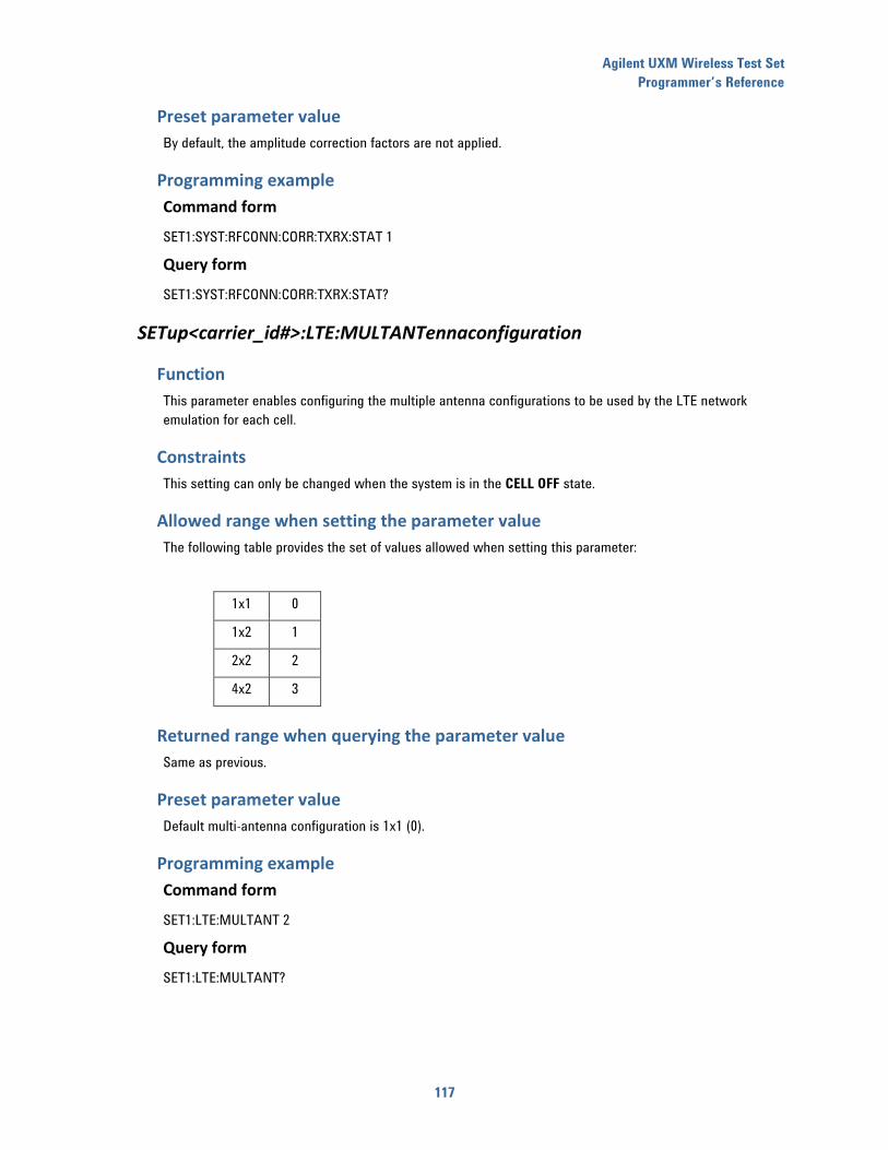
Agilent UXM Wireless Test Set
Programmer’s Reference
117
Preset parameter value
By default, the amplitude correction factors are not applied.
Programming example
Command form
SET1:SYST:RFCONN:CORR:TXRX:STAT 1
Query form
SET1:SYST:RFCONN:CORR:TXRX:STAT?
SETup<carrier_id#>:LTE:MULTANTennaconfiguration
Function
This parameter enables configuring the multiple antenna configurations to be used by the LTE network
emulation for each cell.
Constraints
This setting can only be changed when the system is in the CELL OFF state.
Allowed range when setting the parameter value
The following table provides the set of values allowed when setting this parameter:
1x1 0
1x2 1
2x2 2
4x2 3
Returned range when querying the parameter value
Same as previous.
Preset parameter value
Default multi-antenna configuration is 1x1 (0).
Programming example
Command form
SET1:LTE:MULTANT 2
Query form
SET1:LTE:MULTANT?

Agilent UXM Wireless Test Set
Programmer’s Reference
118
17 “CHANNEL IMPAIRMENTS” configuration commands
SETup<carrier_id#>:LTE:IMPAIRments:AWGN:STATe
Function
This command sets/queries the state of the AWGN generation in the LTE/LTE-A network emulation for
each cell.
You are expected to first configure the AWGN interferer noise level to be generated, then
activate/deactivate the AWGN generation.
Constraints
None.
Allowed range when setting the parameter value
This parameter can have the following values:
0, the AWNG generation is disabled.
1, the AWGN generation is enabled.
Returned range when querying the parameter value
Same as previous.
Preset parameter value
By default the AWGN generation is disabled (0).
Programming example
Command form
SET1:LTE:IMPAIR:AWGN:STAT 1
Query form
SET1:LTE:IMPAIR:AWGN:STAT?
SETup<carrier_id #>:LTE:IMPAIRments:AWGN:POWLVL
Function
This command enables you to configure the power level of the AWGN interferer that is added to the
generated LTE/LTE-A signal for each cell.
You need to set the value of the interferer level prior to enabling the AWGN interferer generation.
Constraints
This command must be issued before enabling the AWGN interferer generation.

Agilent UXM Wireless Test Set
Programmer’s Reference
119
Allowed range when setting the parameter value
The range of allowed values for this parameter depends upon cell configuration.
Returned range when querying the parameter value
As configured by the set form of the command.
Preset parameter value
-41.04 dBm/15kHz.
Programming example
Command form
SET1:LTE:IMPAIR:AWGN:POWLVL -85.6
Query form
SET1:LTE:IMPAIR:AWGN:POWLVL?
SETup<carrier_id#>:LTE:IMPAIRments:FADER:STATe
Function
This command enables you to enable/disable the internal fading channel emulator, as well as the channel
model to be applied, for each cell.
Constraints
None.
Allowed range when setting the parameter value
The following values can be used when using this command:
0, integrated fading channel emulator is disabled;
1, integrated fading channel emulator is set to emulate 3GPP EPA5 channel model;
2, integrated fading channel emulator is set to emulate 3GPP EVA5 channel model;
3, integrated fading channel emulator is set to emulate 3GPP EVA70 channel model;
4, integrated fading channel emulator is set to emulate 3GPP ETU70 channel model;
5, integrated fading channel emulator is set to emulate 3GPP ETU300 channel model;
6, integrated fading channel emulator is set to emulate 3GPP HST channel model
7, integrated fading channel emulator is set to emulate 3GPP CQI channel model
Agilent UXM Wireless Test Set
Programmer’s Reference
120
Returned range when querying the parameter value
Same as previous.
Preset parameter value
By default, the integrated fading channel emulator in the TA/LA is disabled (0).
Programming example
Command form
SET1:LTE:IMPAIR:FADER:STAT 1
Query form
SET1:LTE:IMPAIR:FADER:STAT?
SETup<carrier_id#>:LTE:IMPAIRments:FADER:CORRELATIONmode
Function
This command enables you to configure the correlation mode for the internal fading channel emulator for
each cell. You need to first configure the internal fading channel emulator in order for you to be able to
configure the correlation mode.
Constraints
This setting can only be changed when the integrated fading channel emulator is enabled.
Allowed range when setting the parameter value
The following values can be used when using this command:
0, to set the correlation mode to Low;
1, to set the correlation mode to Medium;
2, to set the correlation mode to High;
Returned range when querying the parameter value
Same as previous.
Preset parameter value
By default, the correlation mode in the TA/LA is low (0).
Programming example
Command form
SET1:LTE:IMPAIR:FADER:CORRELATION 1
Query form
SET1:LTE:IMPAIR:FADER:CORRELATION?
Agilent UXM Wireless Test Set
Programmer’s Reference
121
SETup<carrier_id#>: LTE:IMPAIRments:OCNG:STATe
Function
This command set/queries the state of the OCNG Interferer Configuration in the LTE/LTE-A network
emulation for each cell.
Constraints
None.
Allowed range when setting the parameter value
This parameter can have the following values:
0, the OCNG generation is disabled.
1, the OCNG generation is enabled.
Returned range when querying the parameter value
Same as previous.
Preset parameter value
By default the AWGN generation is disabled (0).
Programming example
Command form
SET1:LTE:IMPAIR:OCNG:STAT 1
Query form
SET1:LTE:IMPAIR:OCNG:STAT?
Agilent UXM Wireless Test Set
Programmer’s Reference
122
18 “POWER CONTROL” configuration commands
CNTRL:LTE:CONNECTion:UL:ULPOWer
Function
This function enables you to specify the target UL power level that the UE uses, commanded by means of
the use of TPC commands. This function is intended to be used together with the function
CNTRL:LTE:CONNECTion:UL:TPCCTRL.
Allowed range when setting the parameter value
You can specify a value within the range -40.00 to 30.00 dBm.
Returned range when querying the parameter value
Same as previous.
Preset parameter value
Default parameter value is -10 dBm
Programming example
Command form
CNTRL:LTE:CONNECT:UL:ULPOW 10
Query form
CNTRL:LTE:CONNECT:UL:ULPOW?
CNTRL:LTE:CONNECTion:UL:TPCCTRL
Function
This function commands the LTE/LTE-A Network Emulator to initiate the transmission of TPC commands to
the UE, commanding it to modify its transmission power.
Allowed range when setting the parameter value
According to the following table:
0 Disables the transmission of TPC commands
1 System continuously transmits TPC commands to increase the UE transmit power
2 System continuously transmits TPC commands to decrease the UE transmit power
3 System transmits TPC commands as needed to maintain the UE transmit power to the
setting specified with the command CNTRL:LTE:CONNECTion:UL:ULPOWer.

Agilent UXM Wireless Test Set
Programmer’s Reference
123
Returned range when querying the parameter value
Same as previous.
Preset parameter value
Default parameter value is 0 (no TPC commands are transmitted to the UE).
Programming example
Command form
CNTRL:LTE:CONNECT:UL:TPCCTRL 1
Query form
CNTRL:LTE:CONNECT:UL:TPCCTRL?

Agilent UXM Wireless Test Set
Programmer’s Reference
124
19 OPERATION COMMANDS
CNTRL:LTE:BCAST:STATe
Function
Sets/queries the broadcast transmission state in the TA/LA. When broadcast transmission is enabled, the
LTE/LTE-A Network Emulator is left in a state in which it can accept incoming ATTACH requests from the
UE (signaling mode enabled).
Allowed range when setting the parameter value
According to the following table:
0 Broadcast transmission is disabled
1 Broadcast transmission is enabled
Returned range when querying the parameter value
Same as previous.
Preset parameter value
Default parameter value is 0 (broadcast transmission is disabled).
Programming example
Command form
CNTRL:LTE:BCAST:STAT 1
Query form
CNTRL:LTE:BCAST:STAT?
CNTRL:LTE:ATTACH:STATe
Function
Queries the UE ATTACH state in the TA/LA. In the signaling enabled mode, this command is used to check if
the UE attach procedure (and additionally the RRC Reconfiguration procedure, in the case that Carrier
Aggregation or CSI-RS activation are enabled) has been completed successfully.
Allowed range when setting the parameter value
None, this command does not accept input parameters.
Returned range when querying the parameter value
According to the following table:
Agilent UXM Wireless Test Set
Programmer’s Reference
125
0 The UE is currently not attached to the UXM BSE simulator or there has been an error
in the RRC Reconfiguration procedure.
1 The UE is currently attached to the UXM base station emulator, and SCC and/or CSI-
RS configuration have been performed successfully.
Preset parameter value
Default parameter value is 0.
Programming example
Command form
Not applicable
Query form
CNTRL:LTE:ATTACH:STAT?
CNTRL:LTE:CONNECTion:DL:STATe
Function
Sets/queries the DL connection status between the UE and the base station emulator. In the signaling
enabled mode, this command can be used to check if the UE is currently being allocated DL grants in the
PDCCH or to trigger the start of these allocations.
Constraints
This setting can only be changed once the UE has finished the attach process to the cell.
Allowed range when setting the parameter value
According to the following table:
0 Stops the allocation of DL BW grants to the UE in the PDCCH
1 Starts the allocation of DL BW grants to the UE in the PDCCH
Returned range when querying the parameter value
Same as previous.
Preset parameter value
Default parameter value is 0.
Agilent UXM Wireless Test Set
Programmer’s Reference
126
Programming example
Command form
CNTRL:LTE:CONNECT:DL:STAT 1
Query form
CNTRL:LTE:CONNECT:DL:STAT?
CNTRL:LTE:CONNECTion:UL:STATe
Function
Sets/queries the UL connection status between the UE and the base station emulator. In the signaling
enabled mode, this command can be used to check if the UE is currently being allocated UL grants in the
PDCCH or to trigger the start of these allocations.
Constraints
This setting can only be changed once the UE has finished the attach process to the cell.
Allowed range when setting the parameter value
According to the following table:
0 Stops the allocation of UL BW grants to the UE in the PDCCH
1 Starts the allocation of UL BW grants to the UE in the PDCCH
Returned range when querying the parameter value
Same as previous.
Preset parameter value
Default parameter value is 0.
Programming example
Command form
CNTRL:LTE:CONNECT:UL:STAT 1
Query form
CNTRL:LTE:CONNECT:UL:STAT?
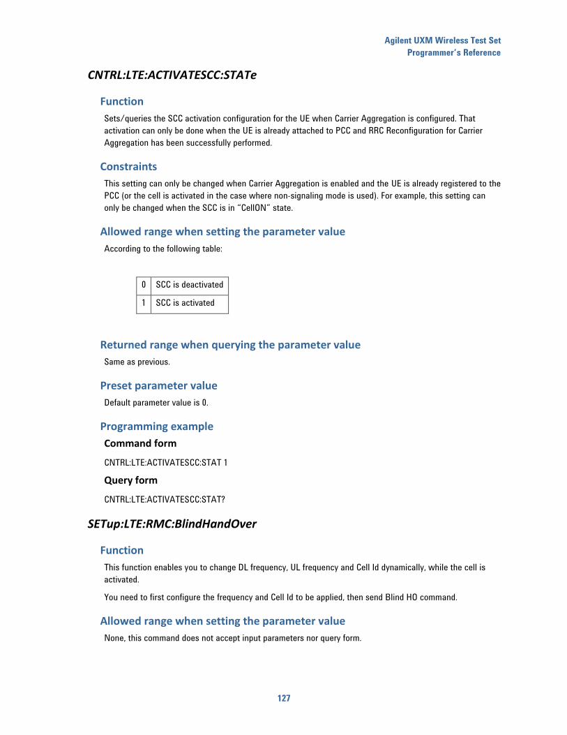
Agilent UXM Wireless Test Set
Programmer’s Reference
127
CNTRL:LTE:ACTIVATESCC:STATe
Function
Sets/queries the SCC activation configuration for the UE when Carrier Aggregation is configured. That
activation can only be done when the UE is already attached to PCC and RRC Reconfiguration for Carrier
Aggregation has been successfully performed.
Constraints
This setting can only be changed when Carrier Aggregation is enabled and the UE is already registered to the
PCC (or the cell is activated in the case where non-signaling mode is used). For example, this setting can
only be changed when the SCC is in “CellON” state.
Allowed range when setting the parameter value
According to the following table:
0 SCC is deactivated
1 SCC is activated
Returned range when querying the parameter value
Same as previous.
Preset parameter value
Default parameter value is 0.
Programming example
Command form
CNTRL:LTE:ACTIVATESCC:STAT 1
Query form
CNTRL:LTE:ACTIVATESCC:STAT?
SETup:LTE:RMC:BlindHandOver
Function
This function enables you to change DL frequency, UL frequency and Cell Id dynamically, while the cell is
activated.
You need to first configure the frequency and Cell Id to be applied, then send Blind HO command.
Allowed range when setting the parameter value
None, this command does not accept input parameters nor query form.
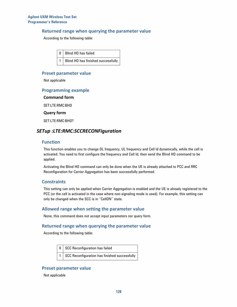
Agilent UXM Wireless Test Set
Programmer’s Reference
128
Returned range when querying the parameter value
According to the following table:
0 Blind HO has failed
1 Blind HO has finished successfully
Preset parameter value
Not applicable
Programming example
Command form
SET:LTE:RMC:BHO
Query form
SET:LTE:RMC:BHO?
SETup :LTE:RMC:SCCRECONFiguration
Function
This function enables you to change DL frequency, UL frequency and Cell Id dynamically, while the cell is
activated. You need to first configure the frequency and Cell Id, then send the Blind HO command to be
applied.
Activating the Blind HO command can only be done when the UE is already attached to PCC and RRC
Reconfiguration for Carrier Aggregation has been successfully performed.
Constraints
This setting can only be applied when Carrier Aggregation is enabled and the UE is already registered to the
PCC (or the cell is activated in the case where non-signaling mode is used). For example, this setting can
only be changed when the SCC is in “CellON” state.
Allowed range when setting the parameter value
None, this command does not accept input parameters nor query form.
Returned range when querying the parameter value
According to the following table:
0 SCC Reconfiguration has failed
1 SCC Reconfiguration has finished successfully
Preset parameter value
Not applicable
Agilent UXM Wireless Test Set
Programmer’s Reference
129
Programming example
Command form
SET:LTE:RMC:SCCRECONF
Query form
SET:LTE:RMC:SCCRECONF?
Agilent UXM Wireless Test Set
Programmer’s Reference
130
20 TX MEASUREMENTS commands
READ:LTE:MEASure:CONSTellation:EVMagnitude?
Function
This function triggers the system to perform a capture of the UL signal transmitted by the UE, followed by
the demodulation of the captured signal, assuming it is a valid LTE/LTE-A transmission, and reports several
EVM values obtained from the demodulated signal.
The different EVM values obtained by this function are:
Average EVM calculated on the PUSCH channel for slot 1
Average EVM calculated on the PUSCH channel for slot 2
Average EVM calculated on the PUCCH channel for slot 1
Average EVM calculated on the PUCCH channel for slot 2
Average EVM calculated on the DMRS signal for slot 1
Average EVM calculated on the DMRS signal for slot 2
These values are returned by this function as a comma-separated list of values, appearing in the same order
as the list provided above.
Allowed range when setting the parameter value
Not applicable, this command only provides a query format.
Returned range when querying the parameter value
Each EVM value is reported as decimal number in the range of 0.00% to 100.00%, following the order
specified in 0.
Preset parameter value
Not applicable
Programming example
Command form
Not applicable
Query form
READ:LTE:MEAS:CONST:EVM?
Agilent UXM Wireless Test Set
Programmer’s Reference
131
READ:LTE:MEASure:FRQERRor?
Function
This function triggers the system to perform a capture of the UL signal transmitted by the UE, followed by
the demodulation of the captured signal, assuming it is a valid LTE/LTE-A transmission, and reports the
frequency error obtained from the demodulated signal.
Allowed range when setting the parameter value
Not applicable, this command only provides a query format.
Returned range when querying the parameter value
The frequency error value is reported as a value measured in Hz.
Preset parameter value
Not applicable
Programming example
Command form
Not applicable
Query form
READ:LTE:MEAS:FRQERR?
READ:LTE:MEASure:CONSTellation:IQOFFset?
Function
This function triggers the system to perform a capture of the UL signal transmitted by the UE, followed by
the demodulation of the captured signal, assuming it is a valid LTE/LTE-A transmission, and reports the IQ
offset obtained from the demodulated signal for both slot 1 and 2, as a comma-separated list of values.
Allowed range when setting the parameter value
Not applicable, this command only provides a query format.
Returned range when querying the parameter value
The IQ offset value is reported as a value measured in dB.
Preset parameter value
Not applicable
Agilent UXM Wireless Test Set
Programmer’s Reference
132
Programming example
Command form
Not applicable
Query form
READ:LTE:MEAS:CONST:IQOFF?
READ:LTE:MEASure:CONSTellation:EVMVSSYMBol?
Function
This function triggers the system to perform a capture of the UL signal transmitted by the UE, followed by
the demodulation of the captured signal, assuming it is a valid LTE transmission, and reports several EVM
values obtained from the demodulated signal.
This function returns EVM measurements results in terms of LTE signal symbols.
These values are returned by this function as a comma-separated list of values, appearing in the same order
as the list provided in the Returned range when querying the parameter value section, below.
Allowed range when setting the parameter value
Not applicable, this command only provides a query format.
Returned range when querying the parameter value
This function returns the following values:
Average EVM value over the LTE sub frame symbols, as a percentage value with two decimal
positions.
Peak EVM value over the LTE sub frame symbols, as a percentage value with two decimal positions.
Symbol index corresponding to the peak EVM measurement within the sub frame, as an integer in
the range from 0 to 6.
Preset parameter value
Not applicable
Programming example
Command form
Not applicable
Query form
READ:LTE:MEAS:CONST:EVMVSSYMB?
Agilent UXM Wireless Test Set
Programmer’s Reference
133
READ:LTE:MEASure:CONSTellation:EVMVSCARRier?
Function
This function triggers the system to perform a capture of the UL signal transmitted by the UE, followed by
the demodulation of the captured signal, assuming it is a valid LTE transmission, and reports several EVM
values obtained from the demodulated signal.
The function returns EVM measurements results in terms of LTE OFDM carriers.
These values are returned by this function as a comma-separated list of values, appearing in the same order
as the list provided in the Returned range when querying the parameter value section, below.
Allowed range when setting the parameter value
Not applicable, this command only provides a query format.
Returned range when querying the parameter value
This function returns the following values:
Average EVM value over the LTE OFDM subcarriers, as a percentage value with two decimal
positions.
Peak EVM value over the LTE OFDM subcarriers, as a percentage value with two decimal positions.
Subcarrier index corresponding to the peak EVM measurement, as an integer in the range from 0 to
2047.
Preset parameter value
Not applicable
Programming example
Command form
Not applicable
Query form
READ:LTE:MEAS:CONST:EVMVSCARR?
SETup:LTE:MEASure:OBW
Function
This function enables you to configure the percentage of channel energy that is considered for the
calculation of the occupied bandwidth of the captured LTE UL signal when calling the corresponding
measurement function.
Allowed range when setting the parameter value
This parameter can be configured as a percentage value between 0.10% and 99.90%.
Agilent UXM Wireless Test Set
Programmer’s Reference
134
Returned range when querying the parameter value
Same as previous.
Preset parameter value
The default value for this parameter is 99.90%.
Programming example
Command form
SET:LTE:MEAS:OBW 95
Query form
SET:LTE:MEAS:OBW?
READ:LTE:MEASure:OBW?
Function
This function triggers the system to perform a capture of the UL signal transmitted by the UE and then,
assuming it is a valid LTE transmission, reports the bandwidth occupied by the captured signal.
Allowed range when setting the parameter value
Not applicable, this command only provides a query format.
Returned range when querying the parameter value
The occupied bandwidth measurement reports the following parameters:
Calculated channel occupied bandwidth, as a value in MHz with four decimal positions.
Calculated channel centroid, as a value in MHz with four decimal positions.
Minimum calculated channel frequency, as a value in MHz with four decimal positions.
Maximum calculated channel frequency, as a value in MHz with four decimal positions.
The values are returned in the form of a list in the same order as they appear in the list above.
Preset parameter value
Not applicable
Programming example
Command form
Not applicable
Query form
READ:LTE:MEAS:OBW?

Agilent UXM Wireless Test Set
Programmer’s Reference
135
READ:LTE:MEASure:SFLatness?
Function
This function triggers the system to perform a capture of the UL signal transmitted by the UE, followed by
the demodulation of the signal, assuming it is a valid LTE transmission and then reports the calculated
spectral flatness (maximum difference between highest and lowest OFDM subcarrier within the complete
channel bandwidth).
Allowed range when setting the parameter value
Not applicable, this command only provides a query format.
Returned range when querying the parameter value
The maximum absolute carrier difference is reported as a value in dB with two decimal positions.
Preset parameter value
Not applicable
Programming example
Command form
Not applicable
Query form
READ:LTE:MEAS:SFL?
READ:LTE:MEASure:CHPOWer?
Function
This function triggers the system to perform a capture of the UL signal transmitted by the UE and then,
assuming it is a valid LTE transmission, reports the channel power of the captured signal.
Allowed range when setting the parameter value
Not applicable, this command only provides a query format.
Returned range when querying the parameter value
The channel power is reported as a value in dBm, with two decimal positions.
Preset parameter value
Not applicable
Agilent UXM Wireless Test Set
Programmer’s Reference
136
Programming example
Command form
Not applicable
Query form
READ:LTE:MEAS:CHPOW?
READ:LTE:MEASure:PAPR?
Function
This function triggers the system to perform a capture of the UL signal transmitted by the UE and then,
assuming it is a valid LTE transmission, reports the PAPR (Peak-Average Power Ratio) captured signal.
Allowed range when setting the parameter value
Not applicable, this command only provides a query format.
Returned range when querying the parameter value
The PAPR is reported as a value in dB, with two decimal positions.
Preset parameter value
Not applicable
Programming example
Command form
Not applicable
Query form
READ:LTE:MEAS:PAPR?

Agilent UXM Wireless Test Set
Programmer’s Reference
137
21 RX MEASUREMENTS commands
SETup:LTE:MEASure:RCVRBLER:MEASLENgth
Function
This function enables you to configure the length, in number of frames, of the receiver measurements to be
performed by the system.
Allowed range when setting the parameter value
This parameter can be configured as a number of frames in the range of 10 to 3600000, in steps of 10.
Returned range when querying the parameter value
Same as previous.
Preset parameter value
The default value for this parameter is 1000 frames.
Programming example
Command form
SET:LTE:MEAS:RCVRBLER:MEASLEN 100
Query form
SET:LTE:MEAS:RCVRBLER:MEASLEN?
READ<carrier:_id#>:LTE:MEASure:RCVRBLER?
Function
This function triggers the system to perform a UE receiver BLER measurement based on the HARQ feedback
provided by the UE along a configured number of consecutive frames.
Allowed range when setting the parameter value
Not applicable.
Returned range when querying the parameter value
The measurement reports two different, although related, values:
HARQ BLER, as a percentage value in the range 0.00% to 100.00%.
MAC level throughput, as a value given in kbps, with four decimal positions.
The parameters are reported as a string with the parameters appearing in the same order in which they are
shown in the list above.
Preset parameter value
Not applicable
Agilent UXM Wireless Test Set
Programmer’s Reference
138
Programming example
Command form
Not applicable
Query form
READ1:LTE:MEAS:RCVRBLER?
READ:LTE:MEASure:TOTALRCVRBLER?
Function
This function triggers the system to perform a UE receiver BLER measurement based on the HARQ feedback
provided by the UE along a configured number of consecutive frames.
This command returns the aggregated (for example: PCC+SCC) BLER and Throughput measurements, so it is
only useful if Carrier Aggregation is enabled.
Allowed range when setting the parameter value
Not applicable
Returned range when querying the parameter value
The measurement reports two different, although related, values:
The aggregated HARQ BLER, as a percentage value in the range 0.00% to 200.00%.
The aggregated MAC level throughput, as a value given in kbps, with four decimal positions.
The parameters are reported as a string with the parameters appearing in the same order in which they are
listed in the list above.
Preset parameter value
Not applicable
Programming example
Command form
Not applicable.
Query form
READ:LTE:MEASURE:TOTALRCVRBLER?
READ:LTE:MEASure:COMPACT:RCVRBLER?
Function
This function triggers the system to perform a UE receiver BLER measurement based on the HARQ feedback
provided by the UE along a configured number of consecutive frames.
This command returns PCC, SCC and the aggregated (for example: PCC+SCC) BLER and Throughput
measurements, so it is only useful if Carrier Aggregation is enabled.
Agilent UXM Wireless Test Set
Programmer’s Reference
139
Allowed range when setting the parameter value
Not applicable
Returned range when querying the parameter value
The measurement reports two different, although related, values:
PCC HARQ BLER, as a percentage value in the range 0.00% to 100.00%.
PCC MAC level throughput, as a value given in kbps, with four decimal positions.
SCC HARQ BLER, as a percentage value in the range 0.00% to 100.00%.
SCC MAC level throughput, as a value given in kbps, with four decimal positions.
The aggregated HARQ BLER, as a percentage value in the range 0.00% to 100.00%.
The aggregated MAC level throughput, as a value given in kbps, with four decimal positions.
The parameters are reported as a string with the parameters appearing in the same order in which they are
listed in the list above.
Preset parameter value
Not applicable
Programming example
Command form
Not applicable.
Query form
READ:LTE:MEAS:COMPACT:RCVRBLER?
READ:LTE:MEASure:TXBLER?
Function
This function triggers the system to perform a UE transmitter BLER measurement based on the HARQ
feedback provided to the UE along a configured number of consecutive frames.
Allowed range when setting the parameter value
Not applicable.
Returned range when querying the parameter value
The measurement reports two different, although related, values:
HARQ BLER, as a percentage value in the range 0.00% to 100.00%.
MAC level throughput, as a value given in kbps, with four decimal positions.
Agilent UXM Wireless Test Set
Programmer’s Reference
140
The parameters are reported as a string with the parameters appearing in the same order in which they are
listed in the list above.
Preset parameter value
Not applicable
Programming example
Command form
Not applicable
Query form
READ:LTE:MEAS:TXBLER?
SETup:LTE:MEASure:CQIREPorting:MEASLENgth
Function
This function enables you to configure the length, in number of frames, of the CQI measurements to be
performed by the system.
Allowed range when setting the parameter value
This parameter can be configured as a number of frames in the range of 50 to 360000, in steps of 10.
Returned range when querying the parameter value
Same as previous.
Preset parameter value
The default value for this parameter is 50 frames.
Programming example
Command form
SET:LTE:MEAS:CQIREP:MEASLEN 100
Query form
SET:LTE:MEAS:RCVRBLER:MEASLEN?
READ<carrier_id#>:LTE:MEASure:CQIREPorting?
Function
This function triggers the system to perform a UE CQI report measurement based on the CQI reports provided
by the UE from the moment the command is issued.
This command returns values after the amount of CQI reports configured through the command
SETup:LTE:MEASure:CQIREPorting:MEASLENgth have been received by the LTE/LTE-A Network Emulator.
You need to have previously activating the CQI reporting functionality in the TA/LA.
Agilent UXM Wireless Test Set
Programmer’s Reference
141
Allowed range when setting the parameter value
Not applicable.
Returned range when querying the parameter value
The measurement reports several parameters:
Minimum CQI reported value during the measurement period.
Maximum CQI reported value during the measurement period.
Average CQI reported value during the measurement period, rounded to closest smaller value.
Median CQI reported value during the measurement period, rounded to closest smaller value.
The parameters are reported as a string with the parameters appearing in the same order in which they are
shown in the list above.
Preset parameter value
Not applicable
Programming example
Command form
Not applicable
Query form
READ1:LTE:MEAS:CQIREP?
READ:LTE:MEASure:RSRPRSRQREPorting?
Function
This function triggers the system to return the latest UE RSRP/RSRQ report provided by the UE at the
moment the command is issued.
You need to have previously activating RSRP/RSRQ reporting functionality in the TA/LA.
Allowed range when setting the parameter value
Not applicable.
Returned range when querying the parameter value
The measurement reports several parameters:
Latest RSRP report value provided by the UE.
Latest RSRQ report value provided by the UE.
The parameters are reported as a string with the parameters appearing in the same order in which they are
shown in the list above.

Agilent UXM Wireless Test Set
Programmer’s Reference
142
Preset parameter value
Not applicable
Programming example
Command form
Not applicable
Query form
READ:LTE:MEAS:RSRPRSRQREP?
READ:LTE:MEASure: DL:IPTHroughput?
Function
This function triggers the system to return the latest UE IP Throughput DL report provided by the UE at the
moment the command is issued.
Allowed range when setting the parameter value
Not applicable.
Returned range when querying the parameter value
The measurement reports the following parameter:
Average, peak and transferred bytes values provided by the UE in DL.
The parameters are reported as a string with the parameters appearing in the same order in which they are
listed in the list above.
Preset parameter value
Not applicable
Programming example
Command form
Not applicable
Query form
READ:LTE:MEAS:DL:IPTH?
READ:LTE:MEASure: UL:IPTHroughput?
Function
This function triggers the system to return the latest UE IP Throughput UL report provided by the UE at the
moment the command is issued.
Allowed range when setting the parameter value
Not applicable.
Agilent UXM Wireless Test Set
Programmer’s Reference
143
Returned range when querying the parameter value
The measurement reports the following parameter:
Average, peak and transferred bytes values provided by the UE in UL.
The parameters are reported as a string with the parameters appearing in the same order in which they are
shown in the list above.
Preset parameter value
Not applicable
Programming example
Command form
Not applicable
Query form
READ:LTE:MEAS:UL:IPTH?
READ:LTE:MEASure: COMPact:IPTHroughput?
Function
This function triggers the system to return the latest brief report about UE IP Throughput in the UE at the
moment the command is issued.
Allowed range when setting the parameter value
Not applicable.
Returned range when querying the parameter value
The measurement reports the following parameter:
IP DL average throughput (bps)
IP DL transferred bytes
IP UL average throughput (bps)
IP UL transferred bytes
PDSCH PCC average throughput (bps)
PDSCH PCC maximum throughput (bps)
PDSCH PCC transferred bytes
PDSCH SCC average throughput (bps)
PDSCH SCC maximum throughput (bps)
PDSCH SCC transferred bytes
OTA DL average throughput (bps)
OTA DL maximum throughput (bps)
OTA DL transferred bytes
OTA UL average throughput (bps)
OTA UL maximum throughput (bps)
OTA UL transferred bytes.
Agilent UXM Wireless Test Set
Programmer’s Reference
144
The parameters are reported as a string with the parameters appearing in the same order in which they are
shown in the list above.
Preset parameter value
Not applicable
Programming example
Command form
Not applicable
Query form
READ:LTE:MEAS:COMP:IPTH?
READ<carrier_id#>:LTE:MEASure:HISTogram:CQI?
Function
This function triggers the system to return the CQI report provided by the UE at the moment the command is
issued.
Allowed range when setting the parameter value
Not applicable.
Returned range when querying the parameter value
The measurement reports the following parameter:
The number of CQI reports received for each one of the CQI values (CQI0, CQI1, CQI2, …,CQI15) related to Codeword 1.
The number of CQI reports received for each one of the CQI values (CQI0, CQI1, CQI2, …,CQI15) related to Codeword 2.
The parameters are reported as a string with the parameters appearing in the same order in which they are
shown in the list above.
Preset parameter value
Not applicable
Programming example
Command form
Not applicable
Query form
READ:LTE:MEAS:HIST:CQI?
Agilent UXM Wireless Test Set
Programmer’s Reference
145
READ<carrier_id#>:LTE:MEASure:HISTogram:RI?
Function
This function triggers the system to return the RI values provided by the UE at the moment the command is
issued.
Allowed range when setting the parameter value
Not applicable.
Returned range when querying the parameter value
The measurement reports the following parameter:
The number of RI reports received with values RI1.
The number of RI reports received with values RI2.
The parameters are reported as a string with the parameters appearing in the same order in which they are
shown in the list above.
Preset parameter value
Not applicable
Programming example
Command form
Not applicable
Query form
READ:LTE:MEAS:HIST:RI?
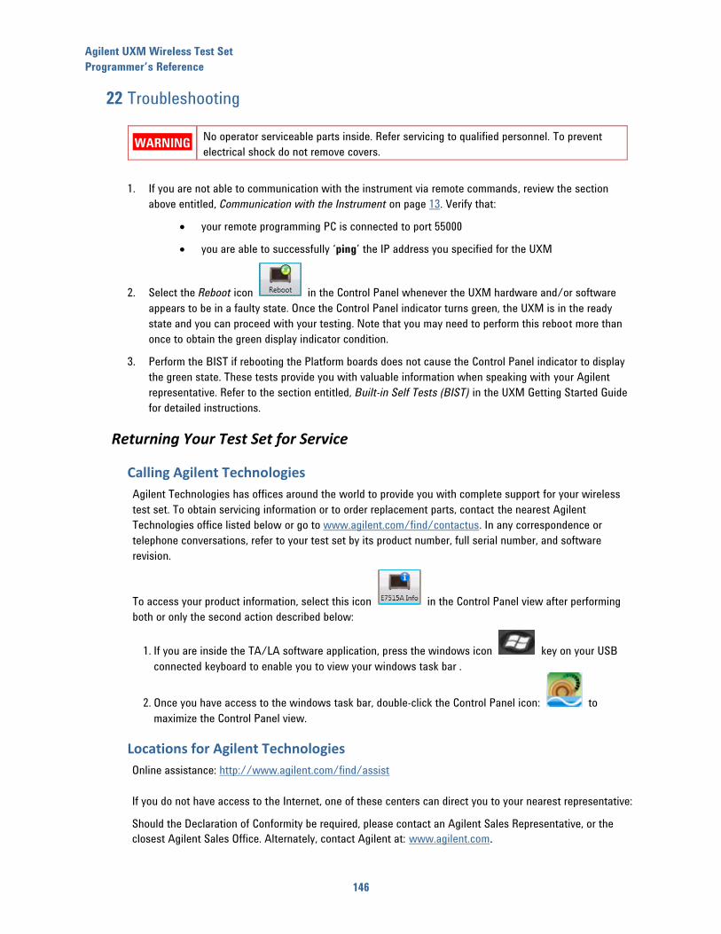
Agilent UXM Wireless Test Set
Programmer’s Reference
146
22 Troubleshooting
WARNING No operator serviceable parts inside. Refer servicing to qualified personnel. To prevent
electrical shock do not remove covers.
1. If you are not able to communication with the instrument via remote commands, review the section
above entitled, Communication with the Instrument on page 13. Verify that:
your remote programming PC is connected to port 55000
you are able to successfully ‘ping’ the IP address you specified for the UXM
2. Select the Reboot icon in the Control Panel whenever the UXM hardware and/or software
appears to be in a faulty state. Once the Control Panel indicator turns green, the UXM is in the ready
state and you can proceed with your testing. Note that you may need to perform this reboot more than
once to obtain the green display indicator condition.
3. Perform the BIST if rebooting the Platform boards does not cause the Control Panel indicator to display
the green state. These tests provide you with valuable information when speaking with your Agilent
representative. Refer to the section entitled, Built-in Self Tests (BIST) in the UXM Getting Started Guide
for detailed instructions.
Returning Your Test Set for Service
Calling Agilent Technologies
Agilent Technologies has offices around the world to provide you with complete support for your wireless
test set. To obtain servicing information or to order replacement parts, contact the nearest Agilent
Technologies office listed below or go to www.agilent.com/find/contactus. In any correspondence or
telephone conversations, refer to your test set by its product number, full serial number, and software
revision.
To access your product information, select this icon in the Control Panel view after performing
both or only the second action described below:
1. If you are inside the TA/LA software application, press the windows icon key on your USB
connected keyboard to enable you to view your windows task bar .
2. Once you have access to the windows task bar, double-click the Control Panel icon: to
maximize the Control Panel view.
Locations for Agilent Technologies
Online assistance: http://www.agilent.com/find/assist
If you do not have access to the Internet, one of these centers can direct you to your nearest representative:
Should the Declaration of Conformity be required, please contact an Agilent Sales Representative, or the
closest Agilent Sales Office. Alternately, contact Agilent at: www.agilent.com.
Agilent UXM Wireless Test Set
Programmer’s Reference
147
Service and Support
Americas
Brazil
(11) 4197 3600
Canada
(877) 894 4414
Mexico
01800 5064 800
United States
(800) 829 4444
Asia Pacific
Australia
1 800 629 485
India
1 800 112 929
Malaysia
1 800 888 848
China
800 810 0189
Japan
0120 (421) 345
Singapore
1 800 375 8100
Hong Kong
800 938 693
Korea
080 769 0800
Taiwan
0800 047 866
Other Asian Countries:
www.agilent.com/find/contactus
Europe & Middle East
Belgium
32 (0) 2 404 93 40
Ireland
1890 924 204
Spain
34 (91) 631 3300
Denmark
45 45 80 12 15
Israel
972-3-9288-504/544
Sweden
0200-88 22 55
Finland
358 (0) 10 855 2100
Italy
39 02 92 60 8484
Switzerland
0800 80 53 53
France
0825 010 700* *0.125 €/minute
Netherlands
31 (0) 20 547 2111
United Kingdom
44 (0) 118 927 6201
Germany
49 (0) 7031 464 6333
Other Unlisted Countries:
www.agilent.com/find/contactus

148
Agilent Technologies, Inc. April 2014