agilent 7200 accurate-mass/q-tof gc/ms system agilent 7200 accurate-mass q-tof gc/ms system...
TRANSCRIPT
Agilent 7200 Accurate-Mass/Q-TOF GC/MS System
Troubleshooting and Maintenance Manual
Agilent Technologies
Notices© Agilent Technologies, Inc. 2012, 2014
No part of this manual may be reproduced in any form or by any means (including elec-tronic storage and retrieval or translation into a foreign language) without prior agree-ment and written consent from Agilent Technologies, Inc. as governed by United States and international copyright laws.
Manual Part NumberG3850-90009
EditionFirst Edition, August 2014
Printed in USA
Agilent Technologies, Inc.5301 Stevens Creek BoulevardSanta Clara, CA 95051
Warranty
The material contained in this docu-ment is provided “as is,” and is sub-ject to being changed, without notice, in future editions. Further, to the max-imum extent permitted by applicable law, Agilent disclaims all warranties, either express or implied, with regard to this manual and any information contained herein, including but not limited to the implied warranties of merchantability and fitness for a par-ticular purpose. Agilent shall not be liable for errors or for incidental or consequential damages in connec-tion with the furnishing, use, or per-formance of this document or of any information contained herein. Should Agilent and the user have a separate written agreement with warranty terms covering the material in this document that conflict with these terms, the warranty terms in the sep-arate agreement shall control.
Safety Notices
CAUTION
A CAUTION notice denotes a hazard. It calls attention to an operating procedure, practice, or the like that, if not correctly performed or adhered to, could result in damage to the product or loss of important data. Do not proceed beyond a CAUTION notice until the indicated conditions are fully understood and met.
WARNING
A WARNING notice denotes a hazard. It calls attention to an operating procedure, practice, or the like that, if not correctly performed or adhered to, could result in personal injury or death. Do not proceed beyond a WARNING notice until the indicated conditions are fully understood and met.
2 Troubleshooting and Maintenance Manual
Contents
1 Introduction
Troubleshooting and Maintenance M
Abbreviations Used 8
The 7200 Accurate-Mass Quadrupole Time-of-Flight GC/MS System 10
7200 Accurate-Mass Q-TOF GC/MS Description 12
Side Panel AC Power Connectors 13
Back Panel Connectors 14
Interfacing Start Events to External Devices 15
Remote control processor 15Remote start signals 15System ready 15Start run input 16
Important Safety Warnings 17
Safety and Regulatory Certifications 20
Intended Use 23
Cleaning/Recycling the Product 23
Moving or Storing the MS 23
2 General Troubleshooting
Troubleshooting Tips and Tricks 26
General Symptoms 27
Chromatographic Symptoms 29
Mass Spectra General Symptoms 34
Pressure Symptoms 36
Temperature Symptoms 38
anual 3
4
Common Types of Errors 40
Air Leaks 45
Contamination 46
3 CI Troubleshooting
Common CI-Specific Problems 50
Troubleshooting Tips and Tricks 51
Air Leaks 52
Pressure-Related Symptoms 55
Signal-Related Symptoms 58
Tuning-Related Symptoms 64
The CI ion source is dirty 65Air leak 65
4 General Maintenance
Before Starting 68
Scheduled maintenance 68Tools, spare parts, and supplies 69High voltage precautions 69Dangerous temperatures 69Chemical residue 70Electrostatic discharge 71
To Refill the EI Calibration Vial 72
Materials needed 72Refill 72
To Refill the IRM Vial 74
Materials needed 74Procedure 74
To Connect the GC Nitrogen Gas Source to the Collision Cell 76
Troubleshooting and Maintenance Manual
Troubleshooting and Maintenance M
Materials needed 76Procedure 76
To Replace the Seals in the RIS Probe 77
Materials needed 77Procedure 77
To Separate the GC from the MS 79
Materials needed 79Procedure 79
To Position the GC Next to the MS 82
Procedure 82
To Move or Store the MS 83
Materials needed 83Procedure 83
To Access the Left Side Lifting Handle 86
Materials needed 86Procedure 87
5 CI Maintenance
To Minimize Foreline Pump Damage from Ammonia 90
To Replace the Methane/Isobutane Gas Purifier 91
To Clean the Reagent Gas Supply Lines 92
To Refill the CI Calibration Vial 93
Materials needed 93Refill 93
6 Vacuum System
Overview 96
Maintaining the Vacuum System 97
Periodic maintenance 97Other procedures 97
anual 5
6
Vacuum System Components 97
Common Vacuum System Problems 98
Foreline Pump 99
To check the oil mist filter 99To check the foreline pump fluid level 100To add foreline pump fluid 100To replace the foreline pump fluid 101
Side Plate 104
Vacuum Seals 104
Calibration Valves 105
EI Calibration Valve 105CI Calibration Valve 106IRM Calibration Valves 107
7 Replacement Parts
To Order Parts 110
Electronics 111
Vacuum System 116
Analyzer 121
RIS Manifold 130
GC/MS Interface 132
Consumables and Maintenance Supplies 133
Troubleshooting and Maintenance Manual
Agilent 7200 Accurate-Mass Q-TOF GC/MS System Troubleshooting and Maintenance Manual
1Introduction
Abbreviations Used 8
The 7200 Accurate-Mass Quadrupole Time-of-Flight GC/MS System 10
7200 Accurate-Mass Q-TOF GC/MS Description 12
Side Panel AC Power Connectors 13
Interfacing Start Events to External Devices 15
Important Safety Warnings 17
Safety and Regulatory Certifications 20
Intended Use 23
Cleaning/Recycling the Product 23
Moving or Storing the MS 23
This section provides general information about the 7200 Accurate-Mass Quadrupole Time-of-Flight (Q-TOF) GC/MS System, including a hardware description and general safety warnings.
7Agilent Technologies
1 Introduction
Abbreviations Used
8
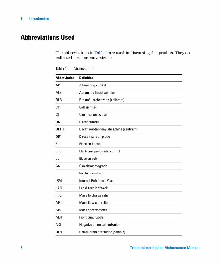
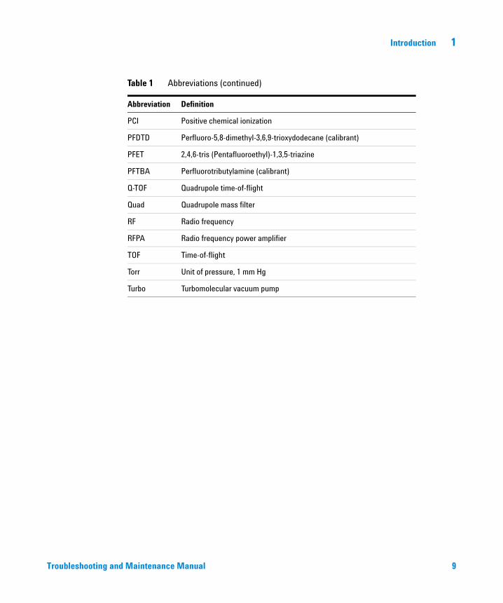
The abbreviations in Table 1 are used in discussing this product. They are collected here for convenience.
Table 1 Abbreviations
Abbreviation Definition
AC Alternating current
ALS Automatic liquid sampler
BFB Bromofluorobenzene (calibrant)
CC Collision cell
CI Chemical ionization
DC Direct current
DFTPP Decafluorotriphenylphosphine (calibrant)
DIP Direct insertion probe
EI Electron impact
EPC Electronic pneumatic control
eV Electron volt
GC Gas chromatograph
id Inside diameter
IRM Internal Reference Mass
LAN Local Area Network
m/z Mass to charge ratio
MFC Mass flow controller
MS Mass spectrometer
MS1 Front quadrupole
NCI Negative chemical ionization
OFN Octafluoronaphthalene (sample)
Troubleshooting and Maintenance Manual
Introduction 1
Troubleshooting and
PCI Positive chemical ionization
PFDTD Perfluoro-5,8-dimethyl-3,6,9-trioxydodecane (calibrant)
PFET 2,4,6-tris (Pentafluoroethyl)-1,3,5-triazine
PFTBA Perfluorotributylamine (calibrant)
Q-TOF Quadrupole time-of-flight
Quad Quadrupole mass filter
RF Radio frequency
RFPA Radio frequency power amplifier
TOF Time-of-flight
Torr Unit of pressure, 1 mm Hg
Turbo Turbomolecular vacuum pump
Table 1 Abbreviations (continued)
Abbreviation Definition
Maintenance Manual 9
1 Introduction
The 7200 Accurate-Mass Quadrupole Time-of-Flight GC/MS System
10
The 7200 Accurate-Mass Quadrupole Time-of-Flight (Q-TOF) GC/MS System is a standalone capillary GC detector for use with the Agilent 7890 Series gas chromatograph. The 7200 Q-TOF features:
• Three turbomolecular vacuum pumps
• Rotary vane foreline pump
• Independently MS-heated EI or CI ion source
• Removable ion source (RIS) probe with bayonet and cooling chamber, which allows quick change from EI to CI source with minimal loss of vacuum in the instrument
• Independently MS-heated hyperbolic quadrupole mass filter, which can be heated to high temperatures, minimizing the contamination typical with low temperature analyses
• Single hexapole collision cell
• Vacuum-insulated flight tube with dual-stage ion mirror
• Fast electronics, allowing fast sampling rates
• Analog to digital detector
• Independently GC-heated GC/MS interface with automatic retraction during source removal
Physical description
The 7200 Q-TOF GC/MS is approximately 48 cm high, 71 cm wide, and 89 cm deep. The flight tube extends 84 cm up over the top of the instrument. The RIS probe handle, when attached, extends 48 cm from the front of the instrument.
The weight of the instrument is 152 kg for the turbo pump mainframe. The attached foreline (roughing) pump weighs an additional 22.2 kg.
The basic components of the instrument are: the frame/cover assemblies, the vacuum system, the GC/MS interface, the removable ion source, the flight tube electronics, the collision cell, the detector, and the analyzer.
Troubleshooting and Maintenance Manual
Introduction 1
Vacuum gauge
Troubleshooting and
The 7200 Q-TOF GC/MS is equipped with four ion vacuum gauges:
• RIS vacuum chamber
• Vacuum manifold chamber
• TOF vacuum manifold chamber
• Turbomolecular vacuum pumps exhaust
The MassHunter Workstation can be used to read the pressure (high vacuum) in the vacuum manifold, at the turbomolecular vacuum pump discharge, and the flight tube.
Ionization modes
The G3851BA 7200 Accurate-Mass Q-TOF GC/MS comes standard with both an EI and CI removable ion source (RIS).
A methane/isobutane gas purifier is provided and is required. It removes oxygen, water, hydrocarbons, and sulfur compounds.
The MS CI system has been optimized to achieve the relatively high source pressure required for CI while still maintaining high vacuum in the collision cell, quadrupole, and TOF tube. Special seals along the flow path of the reagent gas and very small openings in the ion source keep the source gases in the ionization volume long enough for the appropriate reactions to occur.
The interface has special plumbing for reagent gas. A retractable insulating seal fits onto the tip of the interface and is used for both EI and CI.
Switching back and forth between CI and EI sources takes less than 30 minutes with the new removable ion source. The RIS allows the instrument to remain close to pressure, and provides a cooling chamber with N2 purge for rapid source cooling without venting the machine. This saves hours in cycle time over the traditional unit.
Maintenance Manual 11
1 Introduction
7200 Accurate-Mass Q-TOF GC/MS Description
12
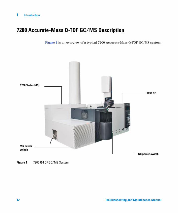
Figure 1 is an overview of a typical 7200 Accurate-Mass Q-TOF GC/MS system.
Figure 1 7200 Q-TOF GC/MS System
7200 Series MS
MS power switch
7890 GC
GC power switch
Troubleshooting and Mainten
ance Manual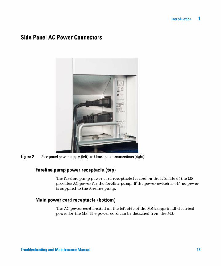
Introduction 1
Side Panel AC Power Connectors
Troubleshooting and
Foreline pump power receptacle (top)
Figure 2 Side panel power supply (left) and back panel connections (right)
The foreline pump power cord receptacle located on the left side of the MS provides AC power for the foreline pump. If the power switch is off, no power is supplied to the foreline pump.
Main power cord receptacle (bottom)
The AC power cord located on the left side of the MS brings in all electrical power for the MS. The power cord can be detached from the MS.
Maintenance Manual 13
1 Introduction
Back Panel Connectors
14
Remote start connector
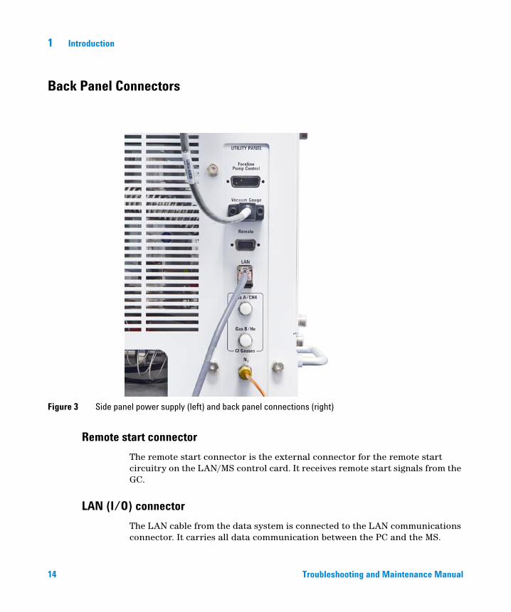
Figure 3 Side panel power supply (left) and back panel connections (right)
The remote start connector is the external connector for the remote start circuitry on the LAN/MS control card. It receives remote start signals from the GC.
LAN (I/O) connector
The LAN cable from the data system is connected to the LAN communications connector. It carries all data communication between the PC and the MS.
Troubleshooting and Maintenance Manual
Introduction 1
Interfacing Start Events to External Devices
Remote control processor
Troubleshooting and
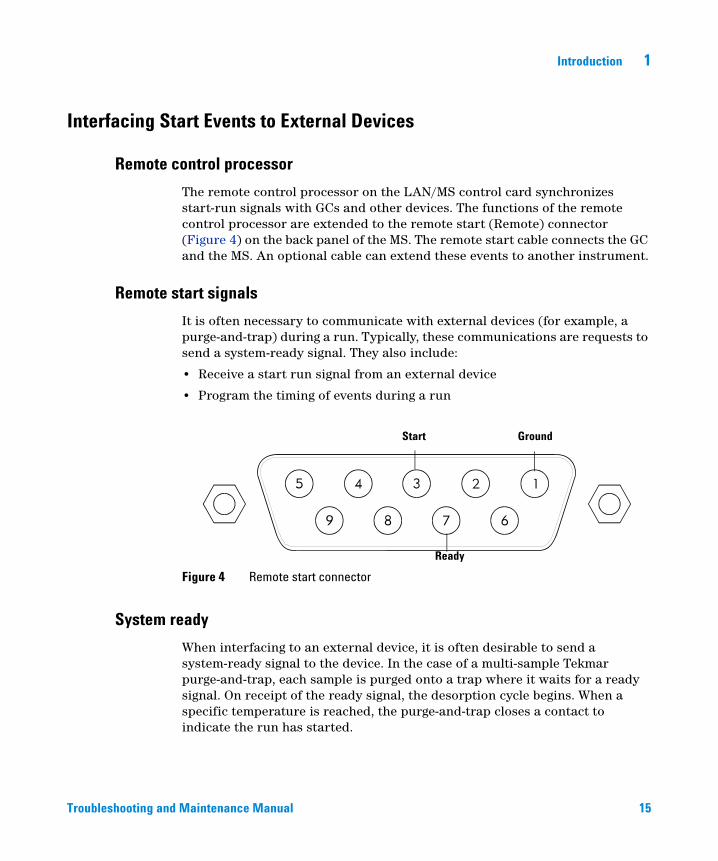
The remote control processor on the LAN/MS control card synchronizes start-run signals with GCs and other devices. The functions of the remote control processor are extended to the remote start (Remote) connector (Figure 4) on the back panel of the MS. The remote start cable connects the GC and the MS. An optional cable can extend these events to another instrument.
Remote start signals
It is often necessary to communicate with external devices (for example, a purge-and-trap) during a run. Typically, these communications are requests to send a system-ready signal. They also include:
• Receive a start run signal from an external device
• Program the timing of events during a run
Figure 4 Remote start connector
Start Ground
Ready
System ready
When interfacing to an external device, it is often desirable to send a system-ready signal to the device. In the case of a multi-sample Tekmar purge-and-trap, each sample is purged onto a trap where it waits for a ready signal. On receipt of the ready signal, the desorption cycle begins. When a specific temperature is reached, the purge-and-trap closes a contact to indicate the run has started.
Maintenance Manual 15
16
1 Introduction
The ready pin on the remote start connector on the GC is held low at all times except when the GC, MS, and data system are all ready. On system ready, a logic high of 5 VDC is present between that pin and any ground. This same high can be detected between the ready and ground pins on the remote start connector on the MS.
Start run input
The best way to generate a start run signal is to use the remote start connector on the GC. Since remote start cables are made for most common devices, this is often the simplest way. A general-purpose remote start cable (Y-Remote Start/Stop, NON APG p/n G1530-61200), is also available that terminates in spade lugs. Care must be taken to ensure that the system is actually ready before the start run signal is sent.
If necessary, the remote start connector on the back of the MS can be used to send the start run signal. A contact closure between the start and ground pins will start the run if the system is ready.
Troubleshooting and Maintenance Manual
Introduction 1
Important Safety Warnings
Troubleshooting and
There are several important safety notices to always keep in mind when using the MS.
Many internal parts of the MS carry dangerous voltages
If the MS is connected to a power source, even if the power switch is off, potentially dangerous voltages exist on:
• The wiring between the MS power cord and the AC power supply
• The AC power supply itself
• The wiring from the AC power supply to the power switch
With the power switch on, potentially dangerous voltages also exist on:
• All electronics boards in the instrument
• The internal wires and cables connected to these boards
• The wires for any heater (oven, detector, inlet, or valve box)
Electrostatic discharge is a threat to MS electronics
WARNING All these parts are shielded by covers. With the covers in place, it should be difficult to accidentally make contact with dangerous voltages. Unless specifically instructed to, never remove a cover unless the detector, inlet, and oven are turned off.
WARNING If the power cord insulation is frayed or worn, the cord must be replaced. Contact your Agilent service representative.
The printed circuit boards in the MS can be damaged by electrostatic discharge. Do not touch any of the boards unless it is absolutely necessary. If you must handle them, wear a grounded wrist strap and take other antistatic precautions.
Maintenance Manual 17
1 Introduction
Precautions to take to prevent an explosion
18
Many parts are dangerously hot
WARNING The use of hydrogen gas is specifically prohibited with this product.
WARNING You MUST make sure the top thumbscrew on the front analyzer side plate and the top thumbscrew on the rear analyzer side plate are both fastened finger-tight. Do not overtighten the thumbscrews; this can cause air leaks.
You MUST leave the collision cell chamber top plate shipping brackets fastened. Do not remove the shipping brackets from the top plate for normal operation; they secure the top plate in the event of an explosion.
WARNING Failure to secure your MS as described above greatly increases the chance of personal injury in the event of an explosion.
Many parts of the GC/MS operate at temperatures high enough to cause serious burns. These parts include, but are not limited to the:
• Inlet
• Oven and its contents
• Valve box
• Column nuts attaching the column to an inlet or detector
• Foreline pump
• GC/MS transfer line
Always cool these areas of the system to room temperature before working on them. They will cool faster if you first set the temperature of the heated zone to room temperature. Turn the zone off after it has reached the setpoint. If you must perform maintenance on hot parts, use a wrench and wear gloves. Whenever possible, cool the part of the instrument that you will be maintaining before you begin working on it.
Troubleshooting and Maintenance Manual
Introduction 1
Troubleshooting and
WARNING Be careful when working behind the instrument. During cool-down cycles, the GC emits hot exhaust that can cause burns.
The oil pan under the standard foreline pump can be a fire hazard
WARNING The insulation around the inlets, detectors, valve box, and the insulation cups is made of refractory ceramic fibers. To avoid inhaling fiber particles, we recommend the following safety procedures: ventilate your work area; wear long sleeves, gloves, safety glasses, and a disposable dust/mist respirator; dispose of insulation in a sealed plastic bag in accordance with local regulations; wash your hands with mild soap and cold water after handling the insulation.
Oily rags, paper towels, and similar absorbents in the oil pan could ignite and damage the pump and other parts of the MS.
Combustible materials (or flammable/nonflammable wicking material) placed
WARNINGunder, over, or around the foreline (roughing) pump constitutes a fire hazard. Keep the pan clean, but do not leave absorbent material such as paper towels in it.Maintenance Manual 19
1 Introduction
Safety and Regulatory Certifications
20
The 7200 Q-TOF GC/MS conforms to the following safety standards:
• Canadian Standards Association (CSA): CAN/CSA-C22.2 No. 61010-1-04
• CSA/Nationally Recognized Test Laboratory (NRTL): UL 61010–1
• International Electrotechnical Commission (IEC): 61010–1
• EuroNorm (EN): 61010–1
The 7200 Q-TOF GC/MS conforms to the following regulations on Electromagnetic Compatibility (EMC) and Radio Frequency Interference (RFI):
• CISPR 11/EN 55011: Group 1, Class A
• IEC/EN 61326-1
• AUS/NZ
This ISM device complies with Canadian ICES-001. Cet appareil ISM est conforme a la norme NMB—001 du Canada.
The 7200 Q-TOF GC/MS is designed and manufactured under a quality system registered to ISO 9001.
Information
The Agilent Technologies 7200 Accurate-Mass Q-TOF GC/MS meets the following IEC (International Electrotechnical Commission) classifications: Equipment Class I, Laboratory Equipment, Installation Category II, and Pollution Degree 2.
This unit has been designed and tested in accordance with recognized safety standards and is designed for use indoors. If the instrument is used in a manner not specified by the manufacturer, the protection provided by the instrument may be impaired. Whenever the safety protection of the MS has been compromised, disconnect the unit from all power sources and secure the unit against unintended operation.
Troubleshooting and Maintenance Manual
Introduction 1
Troubleshooting and
Refer servicing to qualified service personnel. Substituting parts or performing any unauthorized modification to the instrument may result in a safety hazard.
Symbols
Warnings in the manual or on the instrument must be observed during all phases of operation, service, and repair of this instrument. Failure to comply with these precautions violates safety standards of design and the intended use of the instrument. Agilent Technologies assumes no liability for the customer’s failure to comply with these requirements.
See accompanying instructions for more information.
Indicates a hot surface.
Indicates hazardous voltages.
Indicates earth (ground) terminal.
Indicates potential explosion hazard.
Indicates radioactivity hazard.
Indicates electrostatic discharge hazard.
Indicates that you must not discard this electrical/electronic product in domestic household waste.
Maintenance Manual 21
1 Introduction
Electromagnetic compatibility
22
This device complies with the requirements of CISPR 11. Operation is subject to the following two conditions:
• This device may not cause harmful interference.
• This device must accept any interference received, including interference that may cause undesired operation.
If this equipment does cause harmful interference to radio or television reception, which can be determined by turning the equipment off and on, the user is encouraged to try one or more of the following measures:
1 Relocate the radio or antenna.
2 Move the device away from the radio or television.
3 Plug the device into a different electrical outlet, so that the device and the radio or television are on separate electrical circuits.
4 Make sure that all peripheral devices are also certified.
5 Make sure that appropriate cables are used to connect the device to peripheral equipment.
6 Consult your equipment dealer, Agilent Technologies, or an experienced technician for assistance.
Changes or modifications not expressly approved by Agilent Technologies could void the user’s authority to operate the equipment.
Sound emission declaration
Sound pressure
Sound pressure Lp < 70 dB according to EN 27779:1991 and EN ISO 3744:1995.
Schalldruckpegel
Schalldruckpegel LP < 70 dB nach EN 27779:1991 und EN ISO 3744:1995.
Troubleshooting and Maintenance Manual
Introduction 1
Intended Use
Troubleshooting and
Agilent products must only be used in the manner described in the Agilent product user guides. Any other use may result in damage to the product or personal injury. Agilent is not responsible for any damages caused, in whole or in part, by improper use of the products, unauthorized alterations, adjustments or modifications to the products, failure to comply with procedures in Agilent product user guides, or use of the products in violation of applicable laws, rules or regulations.
Cleaning/Recycling the Product
To clean the unit, disconnect the power and wipe down with a damp, lint-free cloth. For recycling, contact your local Agilent sales office.
Moving or Storing the MS
The best way to keep your MS functioning properly is to keep it pumped down and hot, with carrier gas flow. If you plan to move or store your MS, a few additional precautions are required. The MS must remain upright at all times; this requires special caution when moving. The MS should not be left vented to atmosphere for long periods. For more information, see “To Move or Store the MS” on page 83.
Maintenance Manual 23

24
1 Introduction
Troubleshooting and Maintenance Manual
Agilent 7200 Accurate-Mass Q-TOF GC/MS System Troubleshooting and Maintenance Manual
2General Troubleshooting
Troubleshooting Tips and Tricks 26
General Symptoms 27
Chromatographic Symptoms 29
Mass Spectra General Symptoms 34
Pressure Symptoms 36
Temperature Symptoms 38
Common Types of Errors 40
Air Leaks 45
Contamination 46
This is a quick reference to symptoms and possible causes of the most common problems experienced by users. For each symptom, one or more possible causes are listed. In general, the causes listed first are the most likely causes or the easiest to check and correct.
This chapter does not include corrective actions for the possible causes listed. Some of the corrective actions required may be dangerous if performed incorrectly. Do not attempt any corrective actions unless you are sure you know the correct procedure and the dangers involved. See the other chapters in this manual for more information.
If the material in this chapter and in the online help proves insufficient to help you diagnose a problem, contact your Agilent Technologies service representative.
25Agilent Technologies
2 General Troubleshooting
Troubleshooting Tips and Tricks
Rule 1: “Look for what has been changed.”
26
Many problems are introduced accidentally by human actions. Every time any system is disturbed, there is a chance of introducing a new problem.
• If the MS was just pumped down after maintenance, suspect air leaks or incorrect assembly.
• If carrier gas or helium gas purifier was just changed, suspect leaks or contaminated or incorrect gas.
• If the GC column was just replaced, suspect air leaks or a contaminated or bleeding column.
Rule 2: “If complex isn’t working, go back to simple.”
A complex task is not only more difficult to perform but also more difficult to troubleshoot. If you’re having trouble detecting your sample, verify that autotune is successful.
Rule 3: “Divide and conquer.”
This technique is known as “half-split” troubleshooting. If you can isolate the problem to only part of the system, it is much easier to locate.
To determine whether an air leak is in the GC or the MS, you can vent the MS, remove the column, and install the blank interface ferrule. If the leak goes away, it was in the GC.
Troubleshooting and Maintenance Manual
General Troubleshooting 2
General Symptoms
Troubleshooting and
This section describes symptoms you might observe when first turning on the GC/MS system. All of these symptoms would prevent operation of the system.
GC does not turn on
Nothing happens when the GC is switched on. The GC fans do not turn on and the keypad display does not light.
• Disconnected GC power cord
• No voltage or incorrect voltage at the electrical outlet
• Failed fuse in the GC
• GC power supply is not working correctly
MS does not turn on
Nothing happens when the MS is switched on. The foreline pump does not start. The cooling fan for the high-vacuum pump does not turn on.
• Disconnected MS power cord
• No voltage or incorrect voltage at the electrical outlet
• Failed primary fuses - Not user replaceable
• MS electronics are not working correctly
Foreline pump is not operating
The MS is receiving power (the fan is operating) but the foreline pump is not operating.
• A large air leak (usually the analyzer door open) has caused pumpdown failure. You must power cycle the MS to recover from this state.
• Disconnected foreline pump power cord
• Malfunctioning foreline pump
• Check power switch on foreline pump
Maintenance Manual 27
2 General Troubleshooting
MS turns on but then the foreline pump shuts off
28
The MS will shut down both the foreline pump and the turbo pumps if the system fails to pump down correctly. This is usually because of a large air leak or the side plate has not sealed correctly. This feature helps prevent the foreline pump from sucking air through the system, which can damage the analyzer and the turbo pumps.
You must power cycle the MS to recover from this state.
Troubleshooting and Maintenance Manual
General Troubleshooting 2
Chromatographic Symptoms
Troubleshooting and
These are symptoms you may observe in the chromatograms generated by data acquisition. In general, these symptoms do not prevent you from operating your GC/MS system. They indicate, however, that the data you are acquiring may not be the best data obtainable. These symptoms can be caused by instrument malfunctions but are more likely caused by incorrect chromatographic technique.
Two of the symptoms, Low sensitivity and Poor repeatability also apply to mass spectral data.
No peaks
If an analysis shows no chromatographic peaks, only a flat baseline or minor noise, run the automated tune program. If the MS passes tune, the problem is most likely related to the GC. If the MS does not pass tune, the problem is most likely in the MS.
Passes tune
• Incorrect sample concentration
• No analytes present
• Syringe missing from the ALS or not installed correctly
• Injection accidentally made in split mode instead of splitless mode
• Empty or almost empty sample vial
• Dirty GC inlet
• Leaking GC inlet*
• Loose column nut at the GC inlet*
* This could cause a fault condition in the GC that would prevent the GC from operating.
Does not pass tune
• Calibration vial is empty
• Excessive foreline or analyzer chamber pressure
• Very dirty ion source
Maintenance Manual 29
30
2 General Troubleshooting
• Calibration valve is not working correctly
• Bad signal cable connection
• Filament has failed or is not connected correctly
• Bad ion source wiring connection
• Bad detector wiring connection
• Failed MS detector
Peaks are tailing
• Active sites in the sample path
• Injection is too large
• Incorrect GC inlet temperature
• Insufficient column flow
• GC/MS interface temperature is too low
• Ion source temperature is too low
Peaks are fronting
• Column film thickness mismatched with analyte concentration (column overload)
• Initial oven temperature is too low
• Active sites in the sample path
• Injection is too large
• GC inlet pressure too high
• Insufficient column flow
Peaks have flat tops
• Insufficient solvent delay
• Incorrect scale on the display
• Injection is too large
Troubleshooting and Maintenance Manual
General Troubleshooting 2
Peaks have split tops
Troubleshooting and
• Bad injection technique
• Injection is too large
Baseline is rising
• Column bleed
• Other contamination
Baseline is high
• Column bleed
• Other contamination
Baseline is falling
A falling baseline indicates contamination is being swept away. Wait until the baseline reaches an acceptable level. Common causes include:
• Residual air and water from a recent venting
• Column bleed
• Septum bleed
• Splitless injection time too long (inlet is not properly swept, resulting in excess solvent on the column and slow solvent decay)
Maintenance Manual 31
2 General Troubleshooting
Baseline wanders
32
• Insufficient carrier gas supply pressure*
• Malfunctioning flow or pressure regulator*
• Intermittent leak in the GC inlet*
* This could cause a fault condition in the GC that would prevent the GC from operating.
Retention times for all peaks drift – shorter
• Column has been shortened
• Initial oven temperature was increased
• Column is getting old
Retention times for all peaks drift – longer
• Column flow has been reduced
• Initial oven temperature was decreased
• Active sites in the sample path
• Leaks in the GC inlet*
* This could cause a fault condition in the GC that would prevent the GC from operating.
Poor sensitivity
• Incorrect tuning, or tune file that does not match the type of analysis
• Repeller voltage is too low
• Incorrect temperatures (oven, GC/MS interface, ion source, or mass filter)
• Incorrect sample concentration
• Leaking GC inlet*
• Dirty GC inlet
• Incorrect split ratio
• Purge-off time in splitless mode is too short
Troubleshooting and Maintenance Manual
General Troubleshooting 2
Troubleshooting and
• Excessive pressure in the analyzer chamber
• Dirty ion source
• Air leaks between chambers
• Poor filament operation
• Detector is not working correctly
• Incorrect mass filter polarity
• Collision cell voltage
* This could cause a fault condition in the GC that would prevent the GC from operating.
Poor repeatability
• Dirty syringe needle
• Dirty GC inlet
• Leaking GC inlet*
• Injection is too large
• Loose column connections
• Variations in pressure, column flow, and temperature
• Dirty ion source
• Loose connections in the analyzer
• Ground loops
* This could cause a fault condition in the GC that would prevent the GC from operating.
Maintenance Manual 33
2 General Troubleshooting
Mass Spectra General Symptoms
34
This section describes symptoms you might observe in mass spectra. Some of these symptoms will appear in the mass spectra of samples. Others you will observe only in a tune report. Some of these symptoms have causes that can be corrected by the operator. Others, however, require service by an Agilent Technologies service representative.
Two of the chromatographic symptoms, Poor sensitivity and Poor repeatability also apply to mass spectra.
No peaks
• Ion source cables not connected
• Bad connections to or from the detector
• Detector power supply output cable has failed
• Collision cell voltages
• Collision cell gas flow
• Other electronics failure
• Incorrect tune file (inappropriate parameters)
Isotopes are missing or isotope ratios are incorrect
• Wrong precursor or wrong product ion was selected
• MCP and/or PMT voltage is too low
• Repeller voltage is too high
• Wrong ions are chosen
• High background
• Dirty ion source
• Collision cell voltage
• Collision cell gas flow
Troubleshooting and Maintenance Manual
General Troubleshooting 2
High background
Troubleshooting and
• TOF vacuum or Quad vacuum
• Air leak
• Contamination
Maintenance Manual 35
2 General Troubleshooting
Pressure Symptoms
36
This section describes unusual pressure readings and their possible causes. At typical column flow rates (0.5 to 2.0 mL/minute), the foreline pressure will be approximately 16 to 18 mTorr. The Quad pressure with collision cell gas on or off will be approximately 1 × 10⁻⁴ to 2 × 10⁻⁴ Torr. These pressures can vary widely from instrument to instrument so it is very important that you are familiar with the pressures that are typical for your instrument at given carrier and collision gas flows.
Foreline pressure is too high
If the pressure you observe for a given column flow has increased over time, check the following:
• Column (carrier gas) flow is too high
• Collision cell gas flow is too high
• Air leak (usually the side plate is not pushed in or vent valve is open)
• Foreline pump oil level is low or oil is contaminated
• Foreline hose is constricted
• Foreline pump is not working correctly
Troubleshooting and Maintenance Manual
General Troubleshooting 2
Foreline pressure is too low
Troubleshooting and
If the pressures you observe are below 20 mTorr, check for the following:
• Column (carrier gas) flow is too low
• Column plugged or crushed by an overtightened nut
• Collision gas flows are too low
• Empty or insufficient carrier gas supply*
• Bent or pinched carrier gas tubing*
• Foreline gauge is not working correctly
* This could create a fault condition in the GC that would prevent the GC from operating.
Quad pressure is too low
If the pressure you observe is below 1 × 10⁻⁶ Torr with the collision cell gas on or off, check for the following:
• Column (carrier gas) flow is too low
• Collision gas flows are too low
• Column plugged or crushed by overtightened nut
• Empty or insufficient carrier gas supply*
• Bent or pinched carrier gas tubing*
* This could create a fault condition in the GC that would prevent the GC from operating.
Maintenance Manual 37
2 General Troubleshooting
Temperature Symptoms
38
The MS has three heated zones:
• Ion source
• Mass filter
• GC/MS interface
Each heated zone has a heater and temperature sensor. The ion source and mass filter are powered and controlled by the MS. The GC/MS interface is powered and controlled by the GC.
Ion source will not heat up
• High-vacuum pump is off or has not reached normal operating conditions*
• Incorrect temperature setpoint
• Ion source has not had enough time to reach temperature setpoint
• Ion source heater cartridge is not connected*
• Ion source temperature sensor is not connected*
• Ion source heater failed (burned out or shorted to ground)*
• Ion source temperature sensor failed*
• Source power cable is not connected to the quadrupole board*
• MS electronics are not working correctly
* This will cause an error message.
Mass filter (quad) heater will not heat up
• High-vacuum pump is off or has not reached normal operating conditions*
• Incorrect temperature setpoint
• Mass filter has not had enough time to reach temperature setpoint
• Mass filter heater cartridge is not connected*
• Mass filter temperature sensor is not connected*
• Mass filter heater failed (burned out or shorted to ground)*
• Mass filter temperature sensor failed*
• Cable is not connected to the quadrupole board*
Troubleshooting and Maintenance Manual
General Troubleshooting 2
Troubleshooting and
• MS electronics are not working correctly
* This will cause an error message.
GC/MS interface will not heat up
• Incorrect setpoint(s)
• Setpoint entered in wrong heated zone
• GC/MS interface has not had enough time to reach temperature setpoint
• GC is off
• GC experienced a fault and needs to be reset*
• GC/MS interface heater/sensor cable is not connected*
• GC/MS heater failed (burned out)*
• GC/MS sensor failed*
• GC electronics are not working correctly*
* This will cause a GC error message. GC error messages are described in the documentation supplied with your GC.
Maintenance Manual 39
2 General Troubleshooting
Common Types of Errors
40
Sometimes a problem in your MS will cause an error message to appear in the MassHunter Workstation software. Some error messages appear only during tuning. Other messages may appear during tuning or data acquisition.
Some error messages are “latched.” These messages remain active in your data system even if the condition that caused the message has corrected itself. If the cause is removed, these messages can be removed by checking instrument status through the data system.
Difficulty in mass filter electronics
• Pressure in the analyzer chamber is too high
• RFPA is not adjusted correctly
• Mass filter (quad) contacts are shorted or otherwise not working correctly
• Mass filter is not working correctly
• MS electronics are not working correctly
Difficulty with the photo multiplier or microchannel device
• Broad peaks, such as the solvent peak, eluted while the analyzer was on
• MS electronics are not working correctly
Difficulty with the fan
If a cooling fan fault occurs, the vacuum control electronics automatically shut off the high-vacuum pump and the ion source and mass filter heaters. Therefore, the message: “The system is in vent state” may also appear. It is important to note that even though the high-vacuum pump is off, the analyzer chamber may not actually be vented. See “The system is in vent state” on page 43 in this section for precautions to take.
• The fan is disconnected
• The fan has failed
• MS electronics are not working correctly
Troubleshooting and Maintenance Manual
General Troubleshooting 2
Difficulty with the high vacuum pump
Troubleshooting and
This indicates the pump failed to reach 50% of full speed within 10 minutes or experienced a fault.
You must switch the MS off and back on to remove this error message. Be sure the turbo pump has slowed down before switching off the MS. The message will reappear if the underlying problem has not been corrected.
• Large vacuum leak is preventing the turbo pump from reaching 50% of full speed
• Foreline pump is not working correctly
• Turbo pump is not working correctly
• Turbo pump controller is not working correctly
• MS electronics are not working correctly
High foreline pressure
• Excessive carrier gas flow (typically > 5 mL/min)
• Excessive solvent volume injected
• Large vacuum leak
• Severely degraded foreline pump oil
• Collapsed or kinked foreline hose
• Foreline pump is not working correctly
Internal MS communication fault
• MS electronics are not working correctly
Lens supply fault
• Electrical short in the analyzer
• MS cannot maintain the voltage setpoint
• MS electronics are not working correctly
Maintenance Manual 41
2 General Troubleshooting
No peaks found
42
• Emission current was set to 0
• PMT or MCP voltage is too low
• Calibration vial(s) empty or almost empty
• Excessive pressure in the analyzer chamber
• Air leak
• Signal cable is not connected
• Electrical leads to the MCP are not connected correctly
• Electrical leads to the ion source are not connected correctly
• Filament to the source body is shorted
Temperature control disabled
• One of the heater fuses has failed
• MS electronics are not working correctly
Temperature control fault
This indicates that something has gone wrong with the temperature control of either the ion source or the mass filter (quad) heater:
• Source temperature sensor is open
• Source temperature sensor is shorted
• Mass filter (quad) temperature sensor is open
• Mass filter (quad) temperature sensor is shorted
• No heater voltage (heater fuse has probably failed)
• Heater voltage is too low
• Temperature zone has timed out (heater failed, bad heater wiring, or loose temperature sensor)
• Problem with the temperature control electronics
• Source heater is open
• Source heater is shorted
• Mass filter heater is open
• Mass filter heater is shorted
Troubleshooting and Maintenance Manual
General Troubleshooting 2
The high-vacuum pump is not ready
Troubleshooting and
• One of the three Turbo pumps could have failed
• Turbo pump is on but has not had enough time (10 minutes) to reach 80% of its normal operating speed
• Turbo pump is not working correctly
• Foreline pump has not reached its target of 10 Torr after 10 minutes
• MS electronics are not working correctly
The system is in vent state
The message says the system is vented, but if the fault has just occurred it may still be under vacuum and the turbo pump may still be at high speed. Wait at least 30 minutes after seeing this message before you actually vent the MS.
CAUTION Venting the MS too soon after this message appears can damage a turbo pump.
• System was vented purposely (no problem)
• Fan fault has turned off the high-vacuum pump (power cycle the MS to clear the fault)
• Fuse for the high-vacuum pump has failed
• MS electronics are not working correctly
There is no emission current
• Check tune file to be certain that emission current is not = 0
• Filament is not connected properly; try the other filament
• Filament has failed; try the other filament
• MS electronics are not working correctly
There is not enough signal to begin tune
• Corrupted tune file
• Poor mass axis calibration
Maintenance Manual 43
44
2 General Troubleshooting
• Width gain or offset is too high
• Calibration vial(s) empty or almost empty
• Excessive pressure in the analyzer chamber
• Air leak
• MCP or PMT voltage is too low
• Signal cable is not connected
• Electrical leads to the detector are not connected correctly
• Electrical leads to the ion source are not connected correctly
• Filament shorted to the source body
• Collision cell gas flow
• Collision cell voltages
Troubleshooting and Maintenance Manual
General Troubleshooting 2
Air Leaks
Troubleshooting and
Air leaks are a problem for any instrument that requires a vacuum to operate. Leaks are generally caused by vacuum seals that are damaged or not fastened correctly. Symptoms of leaks include:
• Higher than normal analyzer chamber pressure or foreline pressure
• Higher than normal background
• Peaks characteristic of air (m/z 18, 28, 32, and 44 or m/z 14 and 16)
• Poor sensitivity
• Low relative abundance of m/z 502 (this varies with the tune program used)
Leaks can occur in either the GC or the MS. The most likely point for an air leak is a seal you recently opened.
In the GC, most leaks occur in:
• GC inlet septum
• GC inlet column nut
• Broken or cracked capillary column
Leaks can occur in many more places in the MS:
• GC/MS interface column nut
• Side plate O-rings (all the way around)
• Vent valve O-ring
• Calibration valve
• GC/MS interface O-ring (where the interface attaches to the analyzer chamber)
• End plate O-ring
• Turbo pump O-rings
• Collision cell cover O-ring
Maintenance Manual 45
2 General Troubleshooting
Contamination
46
Contamination is usually identified by excessive background in the mass spectra. It can come from the GC or from the MS. The source of the contamination can sometimes be determined by identifying the contaminants. Some contaminants are much more likely to originate in the GC. Others are more likely to originate in the MS.
Contamination originating in the GC typically comes from one of these sources:
• Column or septum bleed
• Dirty GC inlet
• GC inlet liner
• Contaminated syringe
• Poor quality carrier gas
• Dirty carrier gas tubing
• Fingerprints (improper handling of clean parts)
Contamination originating in the MS typically comes from one of the following sources:
• Air leak
• Cleaning solvents and materials
• Foreline pump oil
• Fingerprints (improper handling of clean parts)
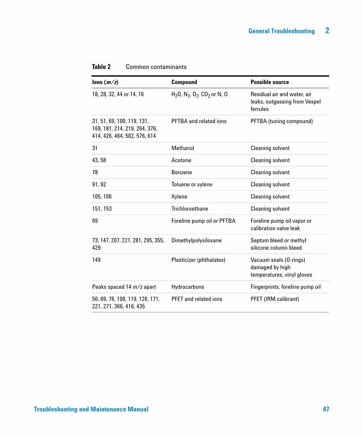
Table 2 lists some of the more common contaminants, the ions characteristic of those contaminants, and the likely sources of those contaminants.
Troubleshooting and Maintenance Manual
General Troubleshooting 2
Troubleshooting and
Table 2 Common contaminants
Ions (m/z) Compound Possible source
18, 28, 32, 44 or 14, 16 H2O, N2, O2, CO2 or N, O Residual air and water, air leaks, outgassing from Vespel ferrules
31, 51, 69, 100, 119, 131,169, 181, 214, 219, 264, 376, 414, 426, 464, 502, 576, 614
PFTBA and related ions PFTBA (tuning compound)
31 Methanol Cleaning solvent
43, 58 Acetone Cleaning solvent
78 Benzene Cleaning solvent
91, 92 Toluene or xylene Cleaning solvent
105, 106 Xylene Cleaning solvent
151, 153 Trichloroethane Cleaning solvent
69 Foreline pump oil or PFTBA Foreline pump oil vapor or calibration valve leak
73, 147, 207, 221, 281, 295, 355, 429
Dimethylpolysiloxane Septum bleed or methyl silicone column bleed
149 Plasticizer (phthalates) Vacuum seals (O-rings)damaged by high temperatures, vinyl gloves
Peaks spaced 14 m/z apart Hydrocarbons Fingerprints, foreline pump oil
50, 69, 76, 100, 119, 126, 171, 221, 271, 366, 416, 435
PFET and related ions PFET (IRM calibrant)
Maintenance Manual 47

48
2 General Troubleshooting
Troubleshooting and Maintenance Manual
Agilent 7200 Accurate-Mass Q-TOF GC/MS System Troubleshooting and Maintenance Manual
3CI Troubleshooting
Common CI-Specific Problems 50
Troubleshooting Tips and Tricks 51
Air Leaks 52
Pressure-Related Symptoms 55
Signal-Related Symptoms 58
Tuning-Related Symptoms 64
This chapter outlines the troubleshooting of the Agilent 7200 Accurate-Mass Q-TOF GC/MS System equipped with the chemical ionization (CI) source. Most of the troubleshooting information in the previous chapter also applies to CI Q-TOFs.
49Agilent Technologies
3 CI Troubleshooting
Common CI-Specific Problems
50
Because of the added complexity of the parts required for CI, there are many potential problems added. By far the greatest number and most serious problems with CI are associated with leaks or contamination in the reagent gas introduction system. NCI is especially sensitive to the presence of air; leaks small enough to cause no problems in PCI can destroy NCI sensitivity.
As with EI, if the MS tunes well and no air leak is present, sample sensitivity problems should be addressed by GC inlet maintenance first.
• Wrong reagent gas
• Reagent gas not hooked up or hooked up to wrong reagent gas inlet port
• Wrong ions entered in tune file
• Wrong tune file selected
• Not enough bakeout time has elapsed since vent (background is too high)
• Wrong column positioning (extending > 4-5 mm past tip of interface)
• Interface tip seal not installed
• EI source installed in CI mode
• EI filament or other EI source parts in CI ion source
• Air leaks in reagent gas flow path
• CI filament has stretched and sagged:
• High emission current
• High temperature
• Filament was defective
• Linear (no inflection point) electron energy (EIEnrgy) ramp
Troubleshooting and Maintenance Manual
CI Troubleshooting 3
Troubleshooting Tips and Tricks
Rule 1: “Look for what has been changed.”
Troubleshooting and
Many problems are introduced accidentally by human actions. Every time any system is disturbed, there is a chance of introducing a new problem.
• If the MS was just pumped down after maintenance, suspect air leaks or incorrect assembly.
• If the reagent gas bottle or gas purifier were just changed, suspect leaks or contaminated or incorrect gas.
• If the GC column was just replaced, suspect air leaks or contaminated or bleeding column.
• If you have just switched ion polarity or reagent gas, suspect the tune file you have loaded in memory. Is it the appropriate file for your mode of operation?
Rule 2: “If complex isn’t working, go back to simple.”
A complex task is not only more difficult to perform, but also more difficult to troubleshoot as well. For example, CI requires more parts to work correctly than EI does.
• If you’re having trouble with NCI, verify that PCI still works.
• If you’re having trouble with other reagent gases, verify that methane still works.
• If you’re having trouble with CI, verify that EI still works.
Rule 3: “Divide and conquer.”
This technique is known as “half-split” troubleshooting. If you can isolate the problem to only part of the system, it is much easier to locate.
• To isolate an air leak, select Shutoff valve. If abundance of m/z 32 decreases, the problem is not in the flow module.
Maintenance Manual 51
3 CI Troubleshooting
Air Leaks
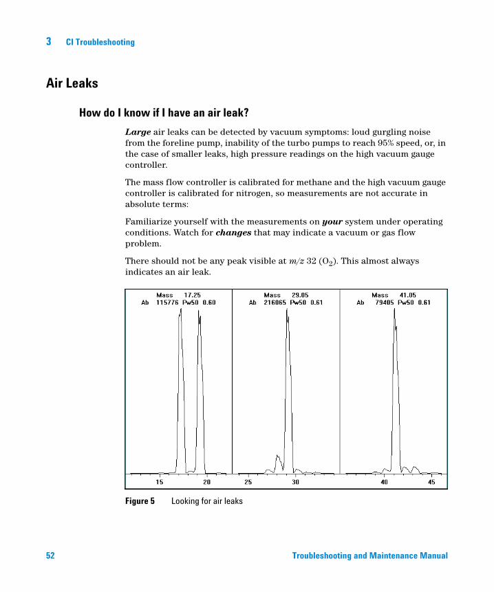
How do I know if I have an air leak?
52
Large air leaks can be detected by vacuum symptoms: loud gurgling noise from the foreline pump, inability of the turbo pumps to reach 95% speed, or, in the case of smaller leaks, high pressure readings on the high vacuum gauge controller.
The mass flow controller is calibrated for methane and the high vacuum gauge controller is calibrated for nitrogen, so measurements are not accurate in absolute terms:
Familiarize yourself with the measurements on your system under operating conditions. Watch for changes that may indicate a vacuum or gas flow problem.
There should not be any peak visible at m/z 32 (O2). This almost always indicates an air leak.
Figure 5 Looking for air leaks
Troubleshooting and Maintenance Manual
CI Troubleshooting 3
Special NCI notes
Troubleshooting and
Since NCI is so extremely sensitive, air leaks that are not detectable in EI or PCI can cause sensitivity problems in NCI. To check for this kind of air leak in NCI, inject OFN. The base peak should be at m/z 272. If the abundance of m/z 238 is much greater than that of m/z 272, you have an air leak.
How do I find the air leak?
1 See Figure 6 and Table 3.
2 Look for the last seal that was disturbed.
• If you just pumped down the MS, press on the sideplate to check for proper seal. Poor alignment between the front analyzer and the GC/MS interface seal can prevent the sideplate from sealing.
• If you just replaced the reagent gas bottle or gas purifier, check the fittings you just opened and refastened.
3 Check for tightness of seals at GC inlet and interface column nuts. Ferrules for capillary columns often loosen after several heat cycles. Do not overtighten the interface nut.
4 If any of the fittings inside the flow module (VCR fittings) were loosened and then retightened, the gasket must be replaced. These gaskets are good for one use only.
CAUTION Do not loosen the nuts on any VCR fittings unless you intend to replace the gaskets. Otherwise, you will create an air leak.
5 Remember that most small air leaks visible in CI mode are located in either the carrier gas or reagent gas flow paths. Leaks into the analyzer chamber are not likely to be seen in CI because of the higher pressure inside the ionization chamber.
6 Half-split the system.
• Close valves starting at the gas select valves (Reagent gas and Carrier gas purge), then close the shutoff valve. See Figure 6 and Table 3.
• Cool and vent the MS, remove the GC column, and cap off the interface.
Maintenance Manual 53
54
3 CI Troubleshooting
If you use argon or other introduced gas to find air leaks, this does not work well for the reagent gas flow system. It takes as long as 15 minutes for the peak to reach the ion source if the leak is at the inlet to the flow module.
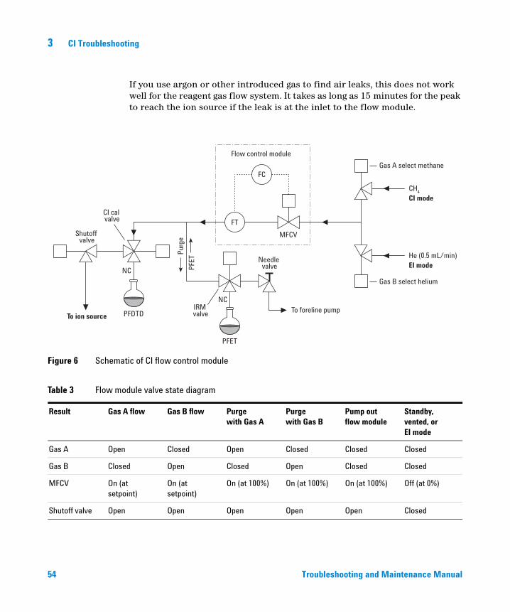
Figure 6 Schematic of CI flow control module
Table 3 Flow module valve state diagram
Result Gas A flow Gas B flow Purge with Gas A
Purge with Gas B
Pump outflow module
Standby, vented, orEI mode
Gas A Open Closed Open Closed Closed Closed
Gas B Closed Open Closed Open Closed Closed
MFCV On (at setpoint)
On (at setpoint)
On (at 100%) On (at 100%) On (at 100%) Off (at 0%)
Shutoff valve Open Open Open Open Open Closed
Shutoff valve
Needle valve
IRM valveTo ion source
Flow control module
To foreline pump
CI mode
Gas A select methane
CH4
EI modeHe (0.5 mL/min)
PFDTD
NC
NC
FT
FC
PFET
MFCV
PFET
Purg
e
CI cal valve
Gas B select helium
Troubleshooting and Maintenance Manual
CI Troubleshooting 3
Pressure-Related Symptoms
Troubleshooting and
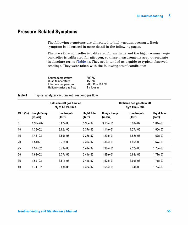
The following symptoms are all related to high vacuum pressure. Each symptom is discussed in more detail in the following pages.
The mass flow controller is calibrated for methane and the high vacuum gauge controller is calibrated for nitrogen, so these measurements are not accurate in absolute terms (Table 4). They are intended as a guide to typical observed readings. They were taken with the following set of conditions:
Source temperature 300 °CQuad temperature 150 °CInterface temperature 280 °C to 320 °CHelium carrier gas flow 1 mL/min
Table 4 Typical analyzer vacuum with reagent gas flow
Collision cell gas flow onN2 = 1.5 mL/min
Collision cell gas flow offN2 = 0 mL/min
MFC (%) Rough Pump (mTorr)
Quadrupole (Torr)
Flight Tube (Torr)
Rough Pump (mTorr)
Quadrupole (Torr)
Flight Tube (Torr)
0 1.36e+02 3.62e-05 3.35e-07 9.13e+01 5.98e-07 1.64e-07
10 1.36+02 3.62e-05 3.37e-07 1.14e+01 1.27e-06 1.65e-07
15 1.43+02 3.66e-05 3.37e-07 1.23e+01 1.62e-06 1.67e-07
20 1.5+02 3.71e-05 3.39e-07 1.31e+01 1.96e-06 1.67e-07
25 1.57+02 3.73e-05 3.41e-07 1.39e+01 2.32e-06 1.70e-07
30 1.63+02 3.77e-05 3.41e-07 1.46e+01 2.64e-06 1.71e-07
35 1.69+02 3.81e-05 3.41e-07 1.52e+01 3.00e-06 1.71e-07
40 1.74+02 3.83e-05 3.43e-07 1.58e+01 3.34e-06 1.72e-07
Maintenance Manual 55
3 CI Troubleshooting
Poor vacuum without reagent gas flow
56
Excess water
Allow the instrument to bake out more and flow reagent gas through the lines to purge any accumulated water.
Air leak
Run Methane Pretune. See the See the Agilent 7200 Accurate-Mass Q-TOF GC/MS System Operation Manual. A visible peak at m/z 32 indicates air in the system. Check for and correct any leaks. See “Air Leaks” on page 52.
The foreline pump is not working properly
For the standard foreline pump, replace the pump oil. If that does not help, contact your local Agilent Technologies Customer Engineer.
The turbo pumps are not working properly
Check the pump speed. It should be at least 95%. Contact your local Agilent Technologies service representative.
High pressure with reagent gas flow
CAUTION Use of ammonia as reagent gas can shorten the life of the foreline pump oil (with standard pump) and possibly of the foreline pump itself. See “To Minimize Foreline Pump Damage from Ammonia” on page 90.
The reagent gas flow rate is too high
On the flow controller, turn down reagent gas flow as appropriate. Verify that reagent ion ratios are correct.
Air leak
Run Methane Pretune. See the See the Agilent 7200 Accurate-Mass Q-TOF GC/MS System Operation Manual. Visible peak at m/z 32 indicates air in the system. Check for and correct any leaks. See the “Air Leaks” on page 52.
Troubleshooting and Maintenance Manual
CI Troubleshooting 3
Pressure does not change when reagent flow is changed
Troubleshooting and
The reagent gas regulator is closed
Check and, if necessary, open the reagent gas regulator.
The reagent gas regulator is set to the wrong pressure
Set the reagent gas regulator to 10 psi (70 kPa) for methane or to 3 to 10 psi (20 to 70 kPa) for isobutane or ammonia.
The valve on the reagent gas bottle is closed
Check and, if necessary, open the valve on the reagent gas bottle.
The reagent gas supply is empty
Check and, if necessary, replace the reagent gas supply.
Reagent lines kinked, bent, pinched, or disconnected
Inspect the reagent lines and repair any defects. Check especially to make sure the reagent line is connected to the rear of the flow module. Be sure the methane line is connected to the Gas A inlet.
GC/MS interface clogged or damaged
Check for flow and repair or replace components as indicated.
Maintenance Manual 57
3 CI Troubleshooting
Signal-Related Symptoms
58
This section describes symptoms related to the signal. The symptom may be too much signal, too little signal, a noisy signal, or an incorrect signal. Signal-related symptoms are generally observed during tuning but may also be observed during data acquisition.
Error messages in autotune due to insufficient signal may vary.
The following symptoms are covered in more detail in this section:
• No peaks. See page 58.
• No or low reagent gas signal. See page 60.
• No or low PFDTD signal. See page 61.
• Excessive noise. See page 62.
• Low signal-to-noise ratio. See page 62.
• Peak at m/z 32. See page 63.
No peaks
When troubleshooting “no peaks” it is important to specify what mode of operation is being used and what expected peaks are not being seen. Always start with methane PCI and verify presence of reagent ions.
No reagent gas peaks in PCI
If MS has been working well and nothing seems to have been changed
• Wrong tune file loaded, or tune file corrupted
• Wrong ion polarity (there are no reagent ions visible in NCI)
• No reagent gas flow; look for background ions and check pressure
• Wrong reagent gas selected for the tune file (looking for wrong ions)
• Large air leak
• Dirty ion source
• Poor vacuum (pump problem). See page 55.
If MS was recently switched from EI to CI
• No reagent gas flow
Troubleshooting and Maintenance Manual
CI Troubleshooting 3
Troubleshooting and
• Analyzer not sealed (big air leak)
• Wrong tune file loaded or tune file corrupted
• Ion source not assembled or connected correctly
• Wrong reagent gas selected for the tune file (looking for wrong ions)
No PFDTD peaks in PCI
• Incorrect reagent gas. There are no PCI PFDTD peaks created with isobutane or ammonia. Switch to methane.
• Analyzer not sealed (big air leak)
• No calibrant in vial
• Defective calibration valve(s)
• Air leak in carrier or reagent gas path
No reagent gas peaks in NCI
• Reagent gases do not ionize in NCI; look for background ions instead
• Verify tune parameters
• If no background ions are visible, go back to methane PCI
No PFDTD calibrant peaks in NCI
• Look for background ions: 35 (Cl–), and 235 (ReO3–)
• Verify tune parameters
• Go back to methane PCI
No sample peaks in NCI
• Look for background ions: 35 (Cl–), and 235 (ReO3–)
• Go back to methane PCI
• Poor quality reagent gas (purity less than 99.99%)
Large peak at m/z 238 in NCI OFN spectrum
• Look for background ions: 35 (Cl–), and 235 (ReO3–)
• Find and fix your small air leak
Maintenance Manual 59
3 CI Troubleshooting
No or low reagent gas signal
60
If you have just installed the CI ion source and have an air leak or large amounts of water in the system and have run one or more autotunes, the ion source is probably dirty now.
Fix the air leak. Clean the ion source. Then bake out for two hours before tuning. See the Agilent 7200 Accurate-Mass Q-TOF GC/MS System Operation Manual.
The wrong reagent gas is flowing.
Turn on the correct reagent gas for your tune file.
Ion polarity is set to Negative. No reagent gas ions are formed in NCI.
Switch to Positive ionization mode.
The reagent gas flow is set too low.
Increase the reagent gas flow.
Reagent gas supply tubing is blocked, kinked, pinched, or disconnected.
Inspect and, if necessary, repair or replace the reagent gas supply tubing.
Carbon has built up on the filament or filament has sagged out of alignment.
Inspect the filament. If necessary, replace the filament.
Too much air or water in the system.
Run the methane pretune. Peaks at m/z 32 and 19 usually indicate air and water, respectively. Bake out and purge the instrument until there is no visible peak at m/z 32 and the peak at m/z 19 is reduced to a very low level. If the peak at m/z 32 does not decrease, an air leak is likely. See “Air Leaks” on page 52 for more information.
The signal cable is not connected.
Check and, if necessary, reconnect the signal cable.
Troubleshooting and Maintenance Manual
CI Troubleshooting 3
Troubleshooting and
The filament or filament support is shorted to the ion source body or repeller.
Inspect the filament. If necessary, realign the filament support arms.
The electron inlet hole is blocked.
Inspect the electron inlet hole. If necessary, clean the hole with a clean toothpick and a slurry of aluminum oxide powder and methanol. If the electron inlet hole is that dirty, the entire ion source probably needs to be cleaned.
Saturated methane/isobutane gas purifier
Replace the gas purifier.
Poor quality methane (purity below 99.99%)
Replace the methane with high-purity methane. If necessary, clean and purge the reagent gas lines and clean the ion source.
No or low PFDTD signal, but reagent ions are normal
You are using any reagent gas but methane in PCI.
Switch to methane.
Wrong or corrupted tune file loaded
Check your tune file.
No PFDTD in the calibrant vial
Inspect the calibration vial on the GC side of the MS. If necessary, fill the vial with PFDTD. Do not fill the vial completely; keep the level at least 0.5 cm from the top of the vial.
The pressure of the methane entering the flow controller is too high.
Make sure the regulator on the methane supply is set to 10 psig (70 kPa).
Maintenance Manual 61
62
3 CI Troubleshooting
The CI ion source is dirty.
Clean the ion source. See the Agilent 7200 Accurate-Mass Q-TOF GC/MS System Operation Manual.
The calibration valve was not purged after the vial was refilled.
Purge the calibration valve as described in “To Refill the CI Calibration Vial” on page 93. Then clean the ion source.
The calibrant vial was overfilled. Excess PFDTD can quench the chemical ionization reactions.
Check the level of the PFDTD in the calibration vial. It should be below the end of the inside tube in the vial.
Poor quality methane (purity below 99.99%)
Replace the methane with high-purity methane. If necessary, clean and purge the reagent gas lines and clean the ion source.
Excessive noise or low signal-to-noise ratio
The GC inlet needs maintenance.
Refer to the GC manual.
The CI ion source is dirty.
Clean the ion source. See the Agilent 7200 Accurate-Mass Q-TOF GC/MS System Operation Manual. for more information.
Poor vacuum
Check the pressure on the high vacuum gauge controller.
Air leak
Run Methane Pretune (in PCI). Large peak at m/z 32 indicates air in the system. Check for and correct any leaks. See “Air Leaks” on page 52.
Troubleshooting and Maintenance Manual
CI Troubleshooting 3
Troubleshooting and
Saturated methane/isobutane gas purifier
Replace the gas purifier. See “To Replace the Methane/Isobutane Gas Purifier” on page 91
Poor quality methane (purity below 99.99%)
Replace the methane with high-purity methane. If necessary, clean and purge the reagent gas lines and clean the ion source.
Reagent gas flows too high (in EI/PCI MSs)
Verify that the reagent gas setup is correct.
Peak at m/z 32
A visible peak at m/z 32 in methane pretune often indicates air in the system.
New or dirty reagent gas supply tubing
Purge the reagent gas supply lines and flow module for at least 60 minutes. See the Agilent 7200 Accurate-Mass Q-TOF GC/MS System Operation Manual.
Air leak
Check for leaks and correct any that you find. See “Air Leaks” on page 52. After all leaks have been corrected, clean the ion source.
Contaminated reagent gas supply. Suspect this if you have recently replaced your gas tank, and you have ruled out air leaks.
Replace the reagent gas supply.
The capillary column is broken or disconnected.
Inspect the capillary column. Make sure it is not broken and it is installed correctly.
Saturated methane/isobutane gas purifier
Replace the gas purifier.
Maintenance Manual 63
3 CI Troubleshooting
Tuning-Related Symptoms
64
This section describes symptoms related to tuning. Most symptoms involve difficulties with tuning or with the results of tuning. The following symptoms are covered in this section:
• CI ion ratio is difficult to adjust or unstable
• Cannot complete autotune
Reagent gas ion ratio is difficult to adjust or unstable
The interface tip seal is incorrectly placed, damaged, or missing.
Inspect the interface tip seal. If necessary, remove and reinstall it to ensure a good seal with the CI ion source. Replace it if it is damaged. Install it if it is missing.
Residual air in the MS or in the reagent gas supply lines
Run the methane pretune. Air will appear as a peak at m/z 32. If this condition is present, purge the reagent gas supply lines and bake out the MS. Continued presence of a large peak at m/z 32 may indicate an air leak. After correcting the problems, you may need to clean the ion source.
Air leak
Run Methane Pretune (in PCI). Large peak at m/z 32 indicates air in the system. Check for and correct any leaks. See “Air Leaks” on page 52.
The reagent gas supply is at the wrong pressure.
Check the regulator on the reagent gas supply. It should be adjusted to 20 psi (140 kPa).
A leak in the reagent gas delivery path. This is especially likely if you have set the methane flow much higher than normal and the ratio is still too low.
Check the reagent gas path. Tighten fittings.
Troubleshooting and Maintenance Manual
CI Troubleshooting 3
Troubleshooting and
The CI ion source is dirty.
Clean the ion source. See the Agilent 7200 Accurate-Mass Q-TOF GC/MS System Operation Manual.
Cannot complete Autotune
Wrong or corrupted tune file
Check the tune parameters.
The m/z 28/27 ion ratio (for methane) is incorrect. The correct ratio should be between 1.5 and 5.0.
If the ion ratio is incorrect, adjust it. See the Agilent 7200 Accurate-Mass Q-TOF GC/MS System Operation Manual.
The CI ion source is dirty.
Clean the ion source. See the Agilent 7200 Accurate-Mass Q-TOF GC/MS System Operation Manual.
Too much air or water in the system
See “Air Leaks” on page 52. After eliminating these problems, clean the ion source.
The CI ion source is dirty
Clean the ion source. See the Agilent 7200 Accurate-Mass Q-TOF GC/MS System Operation Manual.
Air leak
Run Methane Pretune (in PCI). A visible peak at m/z 32 indicates air in the system. Check for and correct any leaks. See “Air Leaks” on page 52. After eliminating all air leaks, clean the ion source.
Maintenance Manual 65

66
3 CI Troubleshooting
Troubleshooting and Maintenance Manual
Agilent 7200 Accurate-Mass Q-TOF GC/MS System Troubleshooting and Maintenance Manual
4General Maintenance
Before Starting 68
To Refill the EI Calibration Vial 72
To Refill the IRM Vial 74
To Connect the GC Nitrogen Gas Source to the Collision Cell 76
To Replace the Seals in the RIS Probe 77
To Separate the GC from the MS 79
To Position the GC Next to the MS 82
To Move or Store the MS 83
This chapter describes maintenance procedures and requirements that are used with all Agilent 7200 Accurate Mass Q-TOF GC/MS Systems.
67Agilent Technologies
4 General Maintenance
Before Starting
68
For your safety, read all of the information in this introduction before performing any maintenance tasks.
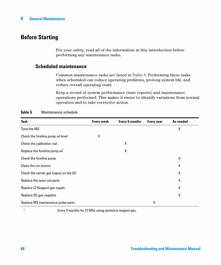
Scheduled maintenance
Common maintenance tasks are listed in Table 5. Performing these tasks when scheduled can reduce operating problems, prolong system life, and reduce overall operating costs.
Keep a record of system performance (tune reports) and maintenance operations performed. This makes it easier to identify variations from normal operation and to take corrective action.
Table 5 Maintenance schedule
Task Every week Every 6 months Every year As needed
Tune the MS X
Check the foreline pump oil level X
Check the calibration vial X
Replace the foreline pump oil* X
Check the foreline pump X
Clean the ion source X
Check the carrier gas trap(s) on the GC X
Replace the worn out parts X
Replace CI Reagent gas supply X
Replace GC gas supplies X
Replace RIS maintenance probe parts X
* Every 3 months for CI MSs using ammonia reagent gas.
Troubleshooting and Maintenance Manual
General Maintenance 4
Tools, spare parts, and supplies
Troubleshooting and
Some of the required tools, spare parts, and supplies are included in the GC shipping kit, MS shipping kit, or MS tool kit. You must supply others yourself. Each maintenance procedure includes a required materials list.
High voltage precautions
When the MS is plugged in, even if the power switch is off, dangerous voltage (200/240 VAC) exists on the wiring and fuses between where the power cord enters the instrument and the power switch.
When the power switch is on, dangerous voltages exist on:
• Electronic circuit boards
• Toroidal transformer
• Wires and cables between these boards
• Wires and cables between these boards and the connectors on the back panel of the MS
• Some connectors on the back panel (for example, the foreline power receptacle)
Normally, all of these parts are shielded by safety covers. As long as the safety covers are in place, it should be difficult to accidentally make contact with dangerous voltages.
Perform no maintenance with the MS turned on or plugged into its power source
WARNINGunless you are instructed to do so by one of the procedures in this chapter.Some procedures in this chapter require access to the inside of the MS while the power switch is on. Do not remove any of the electronics safety covers in any of these procedures. To reduce the risk of electric shock, follow the procedures carefully.
Dangerous temperatures
Many parts in the MS operate at, or reach, temperatures high enough to cause serious burns. These parts include, but are not limited to:
• GC/MS interface
• Analyzer parts
Maintenance Manual 69
70
4 General Maintenance
• Vacuum pumps
Never touch these parts while your MS is on. After the MS is turned off, give these
WARNINGparts enough time to cool before handling them.WARNING The GC/MS interface heater is powered by a heated zone on the GC. The interface heater can be on, and at a dangerously high temperature, even though the MS is off. The GC/MS interface is well insulated. Even after it is turned off, it cools very slowly.
WARNING The foreline pump can cause burns if touched when operating.
The GC inlets and GC oven also operate at very high temperatures. Use the same caution around these parts. See the documentation supplied with your GC for more information.
Chemical residue
Only a small portion of your sample is ionized by the ion source. The majority of any sample passes through the ion source without being ionized. It is pumped away by the vacuum system. As a result, the exhaust from the foreline pump will contain traces of the carrier gas and your samples. Exhaust from the foreline pump also contains tiny droplets of foreline pump oil.
An oil mist filter is supplied with the foreline pump. This filter stops only pump oil droplets. It does not trap any other chemicals. If you are using toxic solvents or analyzing toxic chemicals, install a hose from the mist filter outlet to the outdoors or into a fume hood vented to the outdoors. Be sure to comply with your local air quality regulations.
The oil trap supplied with the foreline pump stops only foreline pump oil. It does not
WARNINGtrap or filter out toxic chemicals. If you are using toxic solvents or analyzing toxic chemicals, vent the exhaust to a safe location.Troubleshooting and Maintenance Manual
General Maintenance 4
Troubleshooting and
The fluid in the foreline pump also collects traces of the samples being analyzed. All used pump fluid should be considered hazardous and handled accordingly. Dispose of used fluid as specified by your local regulations.
When replacing pump fluid, use appropriate chemical-resistant gloves and safety
Electrostatic discharge
WARNINGglasses. Avoid all contact with the fluid.
All of the printed circuit boards in the MS contain components that can be damaged by electrostatic discharge (ESD). Do not handle or touch these boards unless absolutely necessary. In addition, wires, contacts, and cables can conduct ESD to the electronics boards to which they are connected. This is especially true of the mass filter (quadrupole) contact wires, which can carry ESD to sensitive components on the quadrupole board. ESD damage may not cause immediate failure, but it will gradually degrade the performance and stability of your MS.
When you work on or near printed circuit boards or when you work on components with wires, contacts, or cables connected to printed circuit boards, always use a grounded antistatic wrist strap and take other antistatic precautions. The wrist strap should be connected to a known good earth ground. If that is not possible, it should be connected to a conductive (metal) part of the assembly being worked on, but not to electronic components, exposed wires or traces, or pins on connectors.
Take extra precautions, such as a grounded antistatic mat, if you must work on components or assemblies that have been removed from the MS. This includes the analyzer.
To be effective, an antistatic wrist strap must fit snugly (not tight). A loose strap
CAUTIONprovides little or no protection.Antistatic precautions are not 100% effective. Handle electronic circuit boards as little as possible and then only by the edges. Never touch components, exposed traces, or pins on connectors and cables.
Maintenance Manual 71
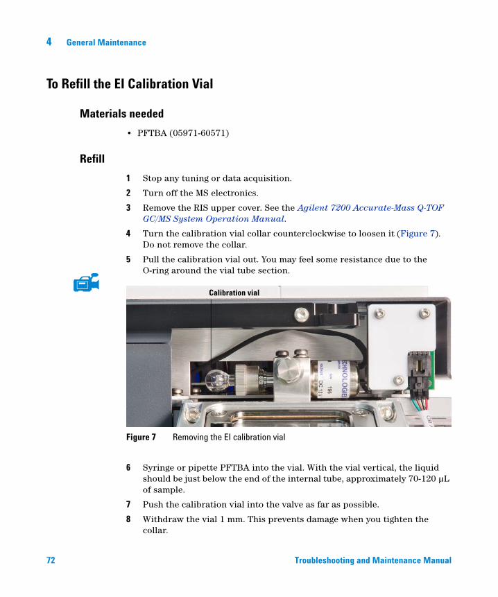
4 General Maintenance
To Refill the EI Calibration Vial
Materials needed
72
• PFTBA (05971-60571)
Refill
1 Stop any tuning or data acquisition.
2 Turn off the MS electronics.
3 Remove the RIS upper cover. See the Agilent 7200 Accurate-Mass Q-TOF GC/MS System Operation Manual.
4 Turn the calibration vial collar counterclockwise to loosen it (Figure 7). Do not remove the collar.
5 Pull the calibration vial out. You may feel some resistance due to the O-ring around the vial tube section.
6 Syringe or pipette PFTBA into the vial. With the vial vertical, the liquid should be just below the end of the internal tube, approximately 70-120 µL of sample.
7 Push the calibration vial into the valve as far as possible.
8 Withdraw the vial 1 mm. This prevents damage when you tighten the collar.
Figure 7 Removing the EI calibration vial
Calibration vial
Troubleshooting and Maintenance Manual
General Maintenance 4
Troubleshooting and
9 Turn the collar clockwise to tighten it.
The collar should be snug but not overly tight. Do not use a tool to tighten the collar. It does not require that much force.
10 Reinstall the RIS upper cover.
11 In the Instrument Control panel, select the MS Tune icon to display the GC-Q-TOF Tune dialog box. Select the Manual Tune tab then select the Ion Source tab to display the ion source parameters.
12 Turn off the Emission by selecting the check box.
13 Purge the calibration valve by selecting the EI Cal Valve check box to open the calibration valve. Close the EI Cal Valve after 30 seconds.
CAUTION After removing a calibrant vial, you must purge the calibration valve. Failure to do so will result in damage to the filaments and the electron multiplier.
Maintenance Manual 73
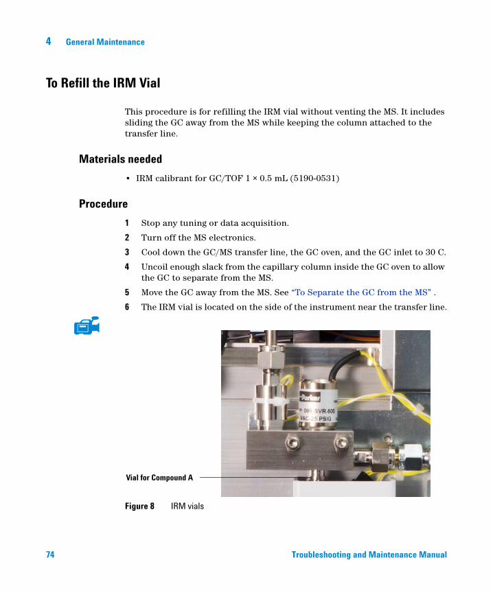
4 General Maintenance
To Refill the IRM Vial
74
This procedure is for refilling the IRM vial without venting the MS. It includes sliding the GC away from the MS while keeping the column attached to the transfer line.
Materials needed
• IRM calibrant for GC/TOF 1 × 0.5 mL (5190-0531)
Procedure
1 Stop any tuning or data acquisition.
2 Turn off the MS electronics.
3 Cool down the GC/MS transfer line, the GC oven, and the GC inlet to 30 C.
4 Uncoil enough slack from the capillary column inside the GC oven to allow the GC to separate from the MS.
5 Move the GC away from the MS. See “To Separate the GC from the MS” .
6 The IRM vial is located on the side of the instrument near the transfer line.
Figure 8 IRM vials
Vial for Compound A
Troubleshooting and Maintenance Manual
General Maintenance 4
Troubleshooting and
7 Remove the metal shield covering the vial.
8 Loosen the collar holding the vial.
9 Remove the vial.
10 Syringe or pipette IRM into the vial. With the vial vertical, the liquid should be just below the end of the internal tube, approximately 70 µL. of sample.
11 Insert the vial into the collar.
12 Push the vial into the collar as far as possible.
13 Withdraw the vial 1 mm. This prevents damage when you tighten the collar.
14 Turn the collar clockwise to tighten it.
The collar should be snug but not overly tight. Do not use a tool to tighten the collar. It does not require that much force.
15 Replace the metal shield.
16 Open the needle valve to the foreline vacuum system located to the right of the IRM vial manifold, to evacuate air from the system.
17 From MassHunter Method Editor, open the Reference Mass Compound valve for 3 minutes.
18 Close the needle valve.
19 Position the GC next to the MS. See“To Position the GC Next to the MS” on page 82.
Maintenance Manual 75
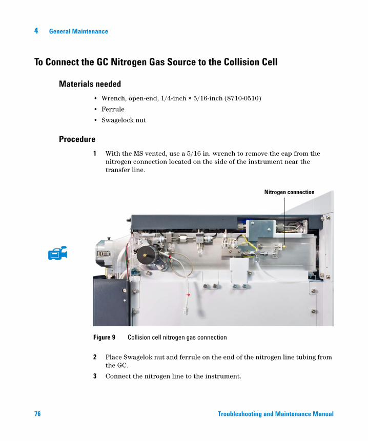
4 General Maintenance
To Connect the GC Nitrogen Gas Source to the Collision Cell
Materials needed
76
• Wrench, open-end, 1/4-inch × 5/16-inch (8710-0510)
• Ferrule
• Swagelock nut
Procedure
1 With the MS vented, use a 5/16 in. wrench to remove the cap from the nitrogen connection located on the side of the instrument near the transfer line.
2 Place Swagelok nut and ferrule on the end of the nitrogen line tubing from the GC.
3 Connect the nitrogen line to the instrument.
Figure 9 Collision cell nitrogen gas connection
Nitrogen connection
Troubleshooting and Maintenance Manual
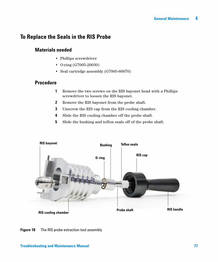
General Maintenance 4
To Replace the Seals in the RIS Probe
Materials needed
Troubleshooting and
• Phillips screwdriver
• O-ring (G7005-20030)
• Seal cartridge assembly (G7005-60070)
Procedure
1 Remove the two screws on the RIS bayonet head with a Phillips screwdriver to loosen the RIS bayonet.
2 Remove the RIS bayonet from the probe shaft.
3 Unscrew the RIS cap from the RIS cooling chamber.
4 Slide the RIS cooling chamber off the probe shaft.
5 Slide the bushing and teflon seals off of the probe shaft.
Figure 10 The RIS probe extraction tool assembly
RIS bayonet Teflon seals
O-ring
Bushing
RIS cooling chamberRIS handle
RIS cap
Probe shaft
Maintenance Manual 77
78
4 General Maintenance
6 Remove the O-ring from the bushing.
7 Wipe the probe shaft and bushing clean with a lint free cloth and alcohol.
8 Insert a new O-ring into the bushing.
9 Slide a new teflon seal onto the probe shaft.
10 Slide the bushing onto the probe shaft.
11 Slide the RIS cooling chamber onto to probe shaft.
12 Thread the RIS cap onto the RIS cooling chamber.
13 Mount the RIS bayonet onto the probe shaft and secure with the Phillips screws.
Troubleshooting and Maintenance Manual
General Maintenance 4
To Separate the GC from the MS
Troubleshooting and
This procedure is used for gaining access to the IRM vials and CI calibration vials or when relocating or storing the instrument.
Materials needed
• Ferrule, blank (5181-3308)
• Interface column nut (05988-20066)
• Wrench, open-end, 1/4-inch × 5/16-inch (8710-0510)
Procedure
WARNING Make sure the GC/MS interface and the analyzer zones are cool (below 100 °C) before you vent the MS. A temperature of 100 °C is hot enough to burn skin; always wear cloth gloves when handling analyzer parts.
WARNING The use of hydrogen gas is specifically prohibited with this product.
CAUTION Be sure the GC oven and the GC/MS interface are cool before turning off carrier gas flow.
WARNING Make sure the GC/MS interface, GC inlet, and GC oven have cooled before you remove the column. These areas can be hot enough to burn skin.
1 Cool down the GC/MS interface, GC inlet, and GC oven.
2 Before separating the GC from the MS, make sure that the capillary column in the GC oven is either disconnected from the transfer line, or has enough slack uncoiled from the column hanger. Transportation of either instrument requires a disconnection of the transfer line. A small separation to access IRM or CI vials does not require disconnection of the transfer line.
Maintenance Manual 79
80
4 General Maintenance
3 The foreline pump may be located on the floor, on the lab bench next to or behind the MS, or under the analyzer chamber at the back of the MS. Move it as needed to provide slack in the tubing and cables.
4 Carefully pull the GC away from the MS until you have access to the GC/MS interface cable (Figure 11). The GC is guided as it slides by the spacer bracket underneath both instruments.
5 Disconnect the GC/MS interface cable. Disconnecting the cable with the GC on can cause a fault condition.
6 Continue to move the GC until you have access to the part requiring maintenance.
Troubleshooting and Maintenance Manual
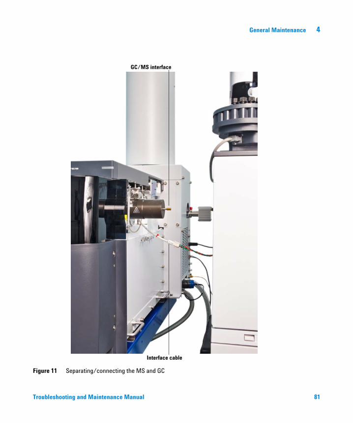
General Maintenance 4
Figure 11 Separating/connecting the MS and GC
GC/MS interface
Interface cable
Troubleshooting and Maintenance Manual 81
4 General Maintenance
To Position the GC Next to the MS
82
This procedure is used to position the GC next to the MS after moving the GC away from the MS to access the IRM vials or CI vial, or after relocating the instrument.
To perform this procedure, the GC/MS interface, GC oven, and GC inlet should be cool.
Procedure
1 Slide the units together and make sure you do not damage the transfer line.
2 Before closing the gap between the MS and the GC, connect the interface cable.
3 Push the GC towards the MS and close the gap.
4 If needed, connect the column to the transfer line. See the Agilent 7200 Accurate-Mass Q-TOF GC/MS System Operation Manual.
5 Wind the excess column slack in the GC oven around the column basket.
6 Turn on the GC and start carrier gas flow.
Troubleshooting and Maintenance Manual
General Maintenance 4
To Move or Store the MS
Materials needed
Troubleshooting and
• Ferrule, blank (5181-3308)
• Interface column nut (05988-20066)
• 2 Wrenches, open-end, 1/4-inch × 5/16-inch (8710-0510)
Procedure
Make sure the GC/MS interface and the analyzer zones are cool (below 100 °C)
WARNINGbefore you vent the MS. A temperature of 100 °C is hot enough to burn skin; always wear cloth gloves when handling analyzer parts.WARNING The use of hydrogen gas is specifically prohibited with this product.
WARNING When the MS is vented, do not put the MassHunter Workstation software into Instrument Control view. Doing so will turn on the interface heater.
CAUTION Be sure the GC oven and the GC/MS interface are cool before turning off the carrier gas flow.
CAUTION Never vent the MS by allowing air in through either end of the foreline hose. Always use the automated procedure in MassHunter Data Acquisition to vent the MS.
Do not exceed the maximum recommended total gas flow.
1 Cool down the GC and MS. See the Agilent 7200 Accurate-Mass Q-TOF GC/MS System Operation Manual.
2 Vent the MS. See the Agilent 7200 Accurate-Mass Q-TOF GC/MS System Operation Manual.
Maintenance Manual 83
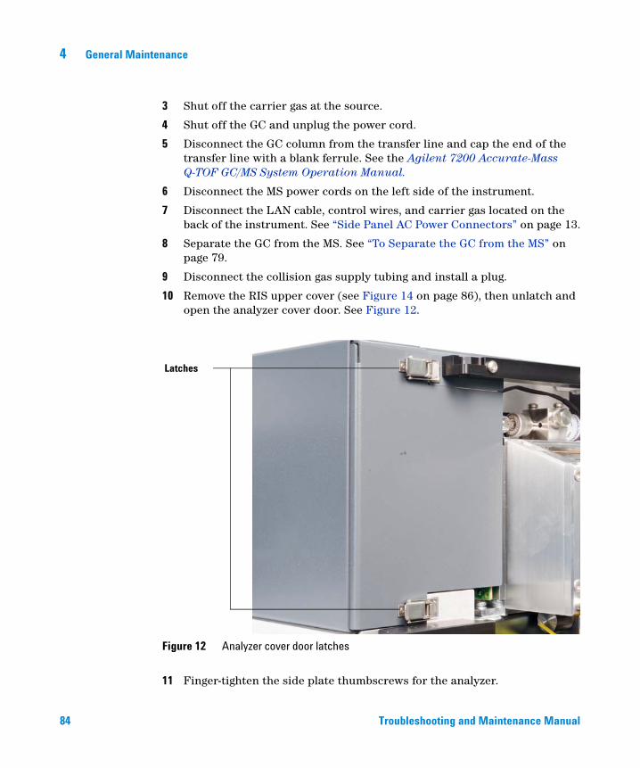
84
4 General Maintenance
3 Shut off the carrier gas at the source.
4 Shut off the GC and unplug the power cord.
5 Disconnect the GC column from the transfer line and cap the end of the transfer line with a blank ferrule. See the Agilent 7200 Accurate-Mass Q-TOF GC/MS System Operation Manual.
6 Disconnect the MS power cords on the left side of the instrument.
7 Disconnect the LAN cable, control wires, and carrier gas located on the back of the instrument. See “Side Panel AC Power Connectors” on page 13.
8 Separate the GC from the MS. See “To Separate the GC from the MS” on page 79.
9 Disconnect the collision gas supply tubing and install a plug.
10 Remove the RIS upper cover (see Figure 14 on page 86), then unlatch and open the analyzer cover door. See Figure 12.
11 Finger-tighten the side plate thumbscrews for the analyzer.
Figure 12 Analyzer cover door latches
Latches
Troubleshooting and Maintenance Manual
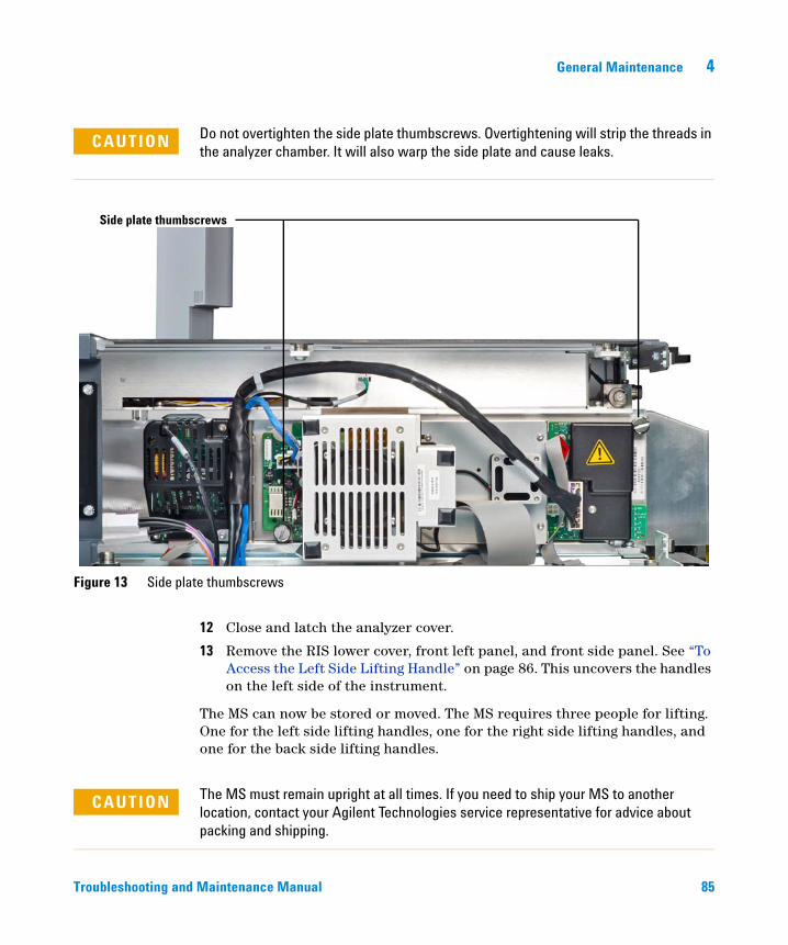
General Maintenance 4
Troubleshooting and
Do not overtighten the side plate thumbscrews. Overtightening will strip the threads in
CAUTIONthe analyzer chamber. It will also warp the side plate and cause leaks.Figure 13 Side plate thumbscrews
Side plate thumbscrews
12 Close and latch the analyzer cover.
13 Remove the RIS lower cover, front left panel, and front side panel. See “To Access the Left Side Lifting Handle” on page 86. This uncovers the handles on the left side of the instrument.
The MS can now be stored or moved. The MS requires three people for lifting. One for the left side lifting handles, one for the right side lifting handles, and one for the back side lifting handles.
CAUTION The MS must remain upright at all times. If you need to ship your MS to another location, contact your Agilent Technologies service representative for advice about packing and shipping.
Maintenance Manual 85
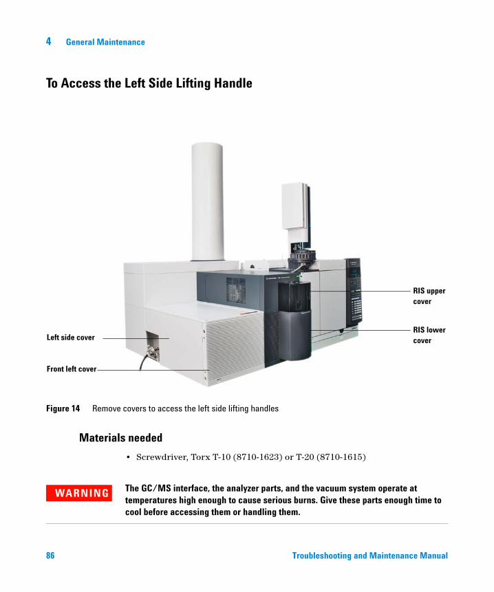
4 General Maintenance
To Access the Left Side Lifting Handle
86
Materials needed
Figure 14 Remove covers to access the left side lifting handles
Front left cover
RIS uppercover
RIS lowercoverLeft side cover
• Screwdriver, Torx T-10 (8710-1623) or T-20 (8710-1615)
The GC/MS interface, the analyzer parts, and the vacuum system operate at
WARNINGtemperatures high enough to cause serious burns. Give these parts enough time to cool before accessing them or handling them.Troubleshooting and Maintenance Manual
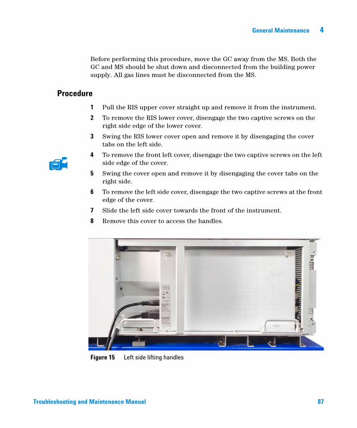
General Maintenance 4
Troubleshooting and
Before performing this procedure, move the GC away from the MS. Both the GC and MS should be shut down and disconnected from the building power supply. All gas lines must be disconnected from the MS.
Procedure
1 Pull the RIS upper cover straight up and remove it from the instrument.
2 To remove the RIS lower cover, disengage the two captive screws on the right side edge of the lower cover.
3 Swing the RIS lower cover open and remove it by disengaging the cover tabs on the left side.
4 To remove the front left cover, disengage the two captive screws on the left side edge of the cover.
5 Swing the cover open and remove it by disengaging the cover tabs on the right side.
6 To remove the left side cover, disengage the two captive screws at the front edge of the cover.
7 Slide the left side cover towards the front of the instrument.
8 Remove this cover to access the handles.
Figure 15 Left side lifting handles
Maintenance Manual 87

88
4 General Maintenance
Troubleshooting and Maintenance Manual
Agilent 7200 Accurate-Mass Q-TOF GC/MS System Troubleshooting and Maintenance Manual
5CI Maintenance
To Minimize Foreline Pump Damage from Ammonia 90
To Replace the Methane/Isobutane Gas Purifier 91
To Clean the Reagent Gas Supply Lines 92
To Refill the CI Calibration Vial 93
This chapter describes maintenance procedures and requirements that are unique to an Agilent 7200 Accurate-Mass Q-TOF GC/MS System equipped with the Chemical Ionization hardware.
89Agilent Technologies
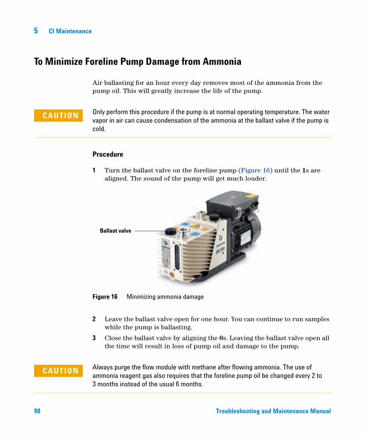
5 CI Maintenance
To Minimize Foreline Pump Damage from Ammonia
90
Air ballasting for an hour every day removes most of the ammonia from the pump oil. This will greatly increase the life of the pump.
CAUTION Only perform this procedure if the pump is at normal operating temperature. The water vapor in air can cause condensation of the ammonia at the ballast valve if the pump is cold.
Procedure
1 Turn the ballast valve on the foreline pump (Figure 16) until the 1s are aligned. The sound of the pump will get much louder.
2 Leave the ballast valve open for one hour. You can continue to run samples while the pump is ballasting.
3 Close the ballast valve by aligning the 0s. Leaving the ballast valve open all the time will result in loss of pump oil and damage to the pump.
Figure 16 Minimizing ammonia damage
Ballast valve
Always purge the flow module with methane after flowing ammonia. The use of
CAUTIONammonia reagent gas also requires that the foreline pump oil be changed every 2 to 3 months instead of the usual 6 months.Troubleshooting and Maintenance Manual
CI Maintenance 5
To Replace the Methane/Isobutane Gas Purifier
Troubleshooting and
Materials needed
• Methane/Isobutane gas purifier (G1999-80410)
• Front ferrule for 1/8-inch tubing (5180-4110)
• Rear ferrule for 1/8-inch tubing (5180-4116)
• Tubing cutter (8710-1709)
The methane/isobutane gas purifier needs to be replaced after four tanks of reagent gas. This frequency may vary depending on purity of the gas and care taken in uncapping and installing the gas purifier. A large leak upstream from the gas purifier can quickly exhaust the reduced metal of the oxygen and moisture traps.
Procedure
1 To install the methane/isobutane gas purifier, follow the instructions on the label for installation and replacement intervals.
CAUTION Do not remove the caps until you are ready to install the gas purifier. Only remove the caps in the gas flow to prevent contamination by air.
WARNING Methane is flammable. Extinguish all flames in the area before turning on gas flow.
2 Disconnect the fittings on the old filter.
3 Remove the ferrules from the tubing at the outlet of the gas purifier. Using the tubing cutter, cut off the end of the tubing with the ferrules.
4 Install the new filter.
5 Purge the new filter.
6 Cap the old filter and prepare it to be sent for regeneration. See the instructions on the label.
Maintenance Manual 91

5 CI Maintenance
To Clean the Reagent Gas Supply Lines
92
Materials needed
• Clean, dry nitrogen
• Heat gun
• Tubing cutter (8710-1709)
Procedure
If the reagent gas lines become contaminated, they can be cleaned.
1 Disconnect the reagent gas tubing from the gas supply, the gas purifier, and the MS.
2 Cap the gas purifier following the instructions on the label.
3 Connect one end of the tubing to a supply of clean, dry nitrogen and turn on gas flow.
4 Use the heat gun to warm the tubing, starting at the supply end and working your way to the free end.
5 Repeat for any other pieces of tubing that need to be cleaned.
6 Reconnect the tubing to the gas supply, gas purifier, and MS. Follow the instructions on the gas purifier label.
WARNING Do not heat the gas tubing when reagent gas is flowing.
CAUTION Do not put liquids into the tubing. Do not heat the tubing when it is connected to the MS.
Troubleshooting and Maintenance Manual
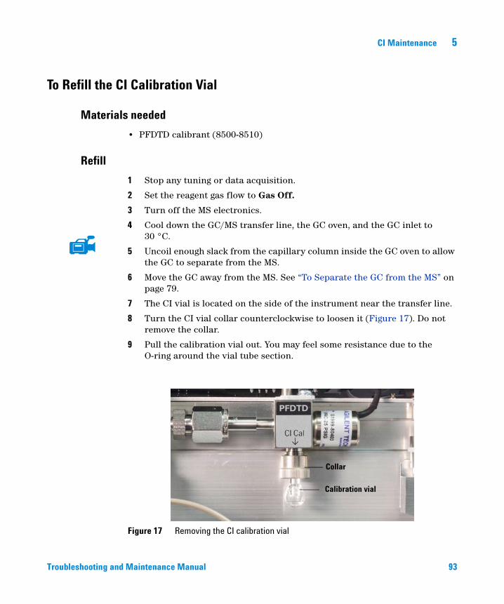
CI Maintenance 5
To Refill the CI Calibration Vial
Materials needed
Troubleshooting and
• PFDTD calibrant (8500-8510)
Refill
1 Stop any tuning or data acquisition.
2 Set the reagent gas flow to Gas Off.
3 Turn off the MS electronics.
4 Cool down the GC/MS transfer line, the GC oven, and the GC inlet to 30 °C.
5 Uncoil enough slack from the capillary column inside the GC oven to allow the GC to separate from the MS.
6 Move the GC away from the MS. See “To Separate the GC from the MS” on page 79.
7 The CI vial is located on the side of the instrument near the transfer line.
8 Turn the CI vial collar counterclockwise to loosen it (Figure 17). Do not remove the collar.
9 Pull the calibration vial out. You may feel some resistance due to the O-ring around the vial tube section.
Figure 17 Removing the CI calibration vial
Calibration vial
Collar
Maintenance Manual 93
5 CI Maintenance
CAUTION Do not rinse the vial with any solvents. Never expose the inside of the vial to chlorinated solvents or isopropyl alcohol or water — this will result in severe loss of CI sensitivity.
94
10 Syringe or pipette PFDTD into the vial. With the vial vertical, the liquid should be just below the end of the internal tube, approximately 70 µL of sample.
11 Push the calibration vial into the valve as far as possible.
12 Withdraw the vial 1 mm. This prevents damage when you tighten the collar.
13 Turn the collar clockwise to tighten it.
The collar should be snug but not overly tight. Do not use a tool to tighten the collar. It does not require that much force.
14 Position the GC next to the MS. See “To Position the GC Next to the MS” on page 82.
15 In the Instrument Control panel, select the MS Tune icon to display the GC Q-TOF Tune dialog box. Select the Manual Tune tab then select the Ion Source tab to display the ion source parameters.
16 Turn off the Emission by selecting the check box.
17 Purge the calibration valve by selecting the CI Cal Valve check box to open the calibration valve. Close the CI Cal Valve after 30 seconds.
After removing a calibrant vial, you must purge the calibration valve. Failure to do so
CAUTIONwill result in damage to the filaments and the electron multiplier.Troubleshooting and Maintenance Manual
Agilent 7200 Accurate-Mass Q-TOF GC/MS System Troubleshooting and Maintenance Manual
6Vacuum System
Overview 96
Maintaining the Vacuum System 97
Vacuum System Components 97
Common Vacuum System Problems 98
Foreline Pump 99
Side Plate 104
Vacuum Seals 104
Calibration Valves 105
This chapter describes maintenance requirements of the Agilent 7200 Accurate Mass Q-TOF GC/MS vacuum system.
95Agilent Technologies
6 Vacuum System
Overview
96
The vacuum system creates the high vacuum (low pressure) required for the GC/MS to operate. Without the vacuum, the molecular mean free path would be very short and ions would collide with air molecules before they could reach the detector. Operation at high pressures also would damage analyzer components.
The Agilent 7200 Accurate-Mass GC/MS System uses four vacuum pumps to obtain the vacuum levels needed. The Agilent 7200 Accurate-Mass GC/MS System uses three turbomolecular (turbo) pumps to create vacuum in the analyzer. These turbo pumps discharge into a manifold operating at foreline pump inlet pressure. The foreline pump discharges to near atmospheric pressure.
Most of the vacuum system operation is automated. Operator interaction and monitoring is accomplished through the data system.
Troubleshooting and Maintenance Manual
Vacuum System 6
Maintaining the Vacuum System
Periodic maintenance
Troubleshooting and
As listed in Table 5 on page 68, some maintenance tasks for the vacuum system must be performed periodically. These include:
• Checking the foreline pump fluid (every week)
• Replacing the foreline pump oil (every 6 months)
• Replace RIS Maintenance Probe parts (yearly)
Failure to perform these tasks as scheduled can result in decreased instrument performance. It can also result in damage to your instrument.
Other procedures
Problems with any of the vacuum system seals in the analyzer usually require the services of Agilent service personnel. See Chapter 2, “General Troubleshooting” on page 25 and see the online help in the MassHunter Workstation software for symptoms that indicate this type of maintenance is required.
Vacuum System Components
The parts of the vacuum system are:
• Foreline (rough) pump
• 3 High-vacuum turbo pumps
• Analyzer chambers
• Collision cell cover
• Side plate (analyzer door)
• Removable Ion Source door and gate valve
• RIS chamber purge and vent valves
• Vacuum seals
• Calibration valves -EI, CI, Mass Reference
• Vacuum control electronics
• Vacuum gauges and gauge control electronics
Maintenance Manual 97
6 Vacuum System
Common Vacuum System Problems
Air leak symptoms
98
The most common problems associated with any vacuum system are air leaks. Symptoms of air leaks include:
• Loud gurgling noise from the foreline pump (very large leak)
• Inability of the turbo pumps to reach 95% speed
• Higher than normal high-vacuum gauge controller readings
The instrument will not pump down successfully unless you press on the side board (analyzer door) when you turn on the MS power. Continue to press until the sound from the foreline pump becomes quieter.
Pumpdown failure shutdown
The system will shut down both the high-vacuum and the foreline pump if the system fails to pump down correctly. It takes approximately 10 minutes for the foreline pump to achieve 10 Torr, which then allows the turbo pumps to start. If a turbo pump speed is below 80% after an additional 10 minutes, the system shuts down.
This is usually because of a large air leak: either the side plate has not sealed correctly or the electronic vent valve is still open.
To restart the MS, find and correct the air leak, then switch the power off and on. Be sure to press on the side plates when turning on the MS power to ensure good seals.
Troubleshooting and Maintenance Manual
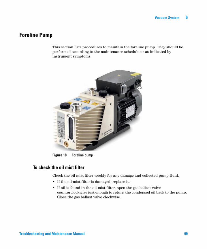
Vacuum System 6
Foreline Pump
Troubleshooting and
This section lists procedures to maintain the foreline pump. They should be performed according to the maintenance schedule or as indicated by instrument symptoms.
Figure 18 Foreline pump
To check the oil mist filter
Check the oil mist filter weekly for any damage and collected pump fluid.
• If the oil mist filter is damaged, replace it.
• If oil is found in the oil mist filter, open the gas ballast valve counterclockwise just enough to return the condensed oil back to the pump. Close the gas ballast valve clockwise.
Maintenance Manual 99
100
6 Vacuum System
When you close the ballast valve, you increase the efficiency of the pump. However, you
To check the foreline pump fluid level
NOTElose oil to the mist filter if you don’t recycle. Check the status of your oil mist filter at least once per week to ensure that it does not fill with oil. If you lose too much oil in the foreline pump, the vacuum will not be maintained, and the MS will vent.
Check the level and color of the pump fluid weekly.
• Check the fluid level in the window of the foreline pump. The fluid level should be between the marks for Max and Min.
• Check that the color of the pump fluid is clear or almost clear with few suspended particles. If the pump fluid is dark or full of suspended particles, replace it.
Never add or replace the foreline pump fluid while the pump is on.
WARNINGRecord this procedure in the Maintenance Logbook.
To add foreline pump fluid
NOTE
Add pump fluid when the pump fluid level is low.
Materials needed
• Funnel
• Gloves, chemical resistant, clean, lint free (p/n 9300-1751)
• Foreline pump fluid (Inland 45 oil, p/n 6040-0834)
• Safety glasses (goggles)
Never add pump fluid while the pump is on.
WARNINGTroubleshooting and Maintenance Manual
Vacuum System 6
Troubleshooting and
The fill cap and pump may be dangerously hot. Check that the fill cup and pump are
WARNINGcool before you touch them.Use only Foreline pump fluid (Inland 45 oil, p/n 6040-0834). Any other fluids can
CAUTIONsubstantially reduce pump life and invalidates the pump warranty.Procedure
1 Vent and turn off the instrument. See the Agilent 7200 Accurate-Mass Q-TOF GC/MS System Operation Manual.
2 Unplug the instrument power cord from the electrical outlet.
3 Remove the fill cap on the foreline pump (see Figure 63).
4 Add new pump fluid until the fluid level is near, but not over the maximum mark beside the fluid level window (see Figure 63).
5 Reinstall the fill cap.
6 Wipe off all excess oil around and underneath of the pump.
7 Reconnect the power cord.
8 Start up the instrument. See the Agilent 7200 Accurate-Mass Q-TOF GC/MS System Operation Manual.
To replace the foreline pump fluid
Replace the pump fluid every six months or sooner if the fluid appears dark or cloudy.
Materials needed
• Container for catching old pump fluid
• Funnel
• Gloves, chemical resistant, clean, lint free (p/n 9300-1751)
• Rough pump fluid (Inland 45 oil, p/n 6040-0834)
• Screwdriver, flat-bladed, large (p/n 8710-1029)
• Safety glasses (goggles)
Maintenance Manual 101
102
6 Vacuum System
Never add pump fluid while the pump is on.
WARNINGThe fill cap and pump may be dangerously hot. Check that the fill cap and pump are
WARNINGcool before you touch them.Do not touch the fluid. The residue from some samples are toxic. Properly dispose of
WARNINGthe fluid.Use only Foreline pump fluid (Inland 45 oil, p/n 6040-0834). Any other fluids can
CAUTIONsubstantially reduce pump life and invalidates the pump warranty.Procedure
1 Turn off the instrument. See the Agilent 7200 Accurate-Mass Q-TOF GC/MS System Operation Manual.
2 Unplug the power cord from the instrument.
3 Place a container under the drain plug of the foreline pump (see Figure 63 on page 118).
4 Remove the fill cap (see Figure 63 on page 118), then open the drain plug. Drain the fluid completely by raising the motor end of the pump up.
5 Reinstall the drain plug.
6 Pour in new pump fluid until the fluid level is near, but not above the maximum mark beside the fluid level window (see Figure 63 on page 118).
7 Reinstall the fill cap.
8 Reconnect the power cord.
9 Start up the instrument. See the Agilent 7200 Accurate-Mass Q-TOF GC/MS System Operation Manual.
10 Pump down for 30 min, then inspect the pump for leaks.
11 Continue pumping down overnight and inspect the pump for leaks the next day.
Troubleshooting and Maintenance Manual
Vacuum System 6
The oil pan under the foreline pump can be a fire hazard
Troubleshooting and
Oily rags, paper towels, and similar absorbents in the oil pan could ignite and damage the pump and other parts of the MS.
Combustible materials (or flammable/nonflammable wicking material) placed
WARNINGunder, over, or around the foreline (roughing) pump constitutes a fire hazard. Keep the pan clean, but do not leave absorbent material such as paper towels in it.Maintenance Manual 103
6 Vacuum System
Side Plate
104
The side plate covers the large opening in the side of the manifold. There are no user serviceable part accessible through the hinged side plate. The analyzer assembly is attached to the side plate inside the analyzer chamber.
Several electrical feedthroughs are built into the side plate. Wires connect the feedthroughs to analyzer components.
Thumbscrews are located at each end of the side plate. We recommend that the thumbscrews be loosely tightened
Vacuum Seals
CAUTION Fasten the side plate thumbscrews for shipping or storage only. For normal operation, both thumbscrews should be loose. Overtightening will warp the side plate and cause air leaks. Do not use a tool to tighten the side plate thumbscrews.
CAUTION When you turn on the power to pump down the MS, be sure to press on the side board to ensure good seals.
Several types of Viton elastomer O-ring seals are used to prevent air leaks into the analyzer chamber. All these O-rings, and the surfaces to which they seal, must be kept clean and protected from nicks and scratches. A single hair, piece of lint, or scratch can produce a serious vacuum leak. Three of the O-rings are lightly lubricated with Apiezon-L vacuum grease: the side plate O-rings and the vent valve O-ring.
Contact Agilent to have these vacuum seals serviced.
Troubleshooting and Maintenance Manual
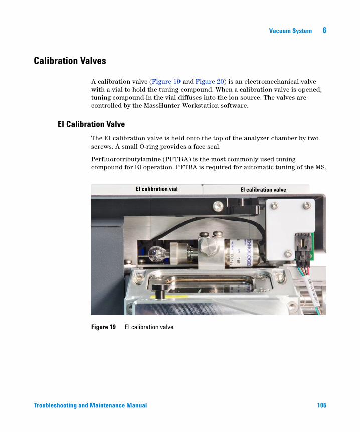
Vacuum System 6
Calibration Valves
Troubleshooting and
A calibration valve (Figure 19 and Figure 20) is an electromechanical valve with a vial to hold the tuning compound. When a calibration valve is opened, tuning compound in the vial diffuses into the ion source. The valves are controlled by the MassHunter Workstation software.
EI Calibration Valve
The EI calibration valve is held onto the top of the analyzer chamber by two screws. A small O-ring provides a face seal.
Perfluorotributylamine (PFTBA) is the most commonly used tuning compound for EI operation. PFTBA is required for automatic tuning of the MS.
Figure 19 EI calibration valve
EI calibration valveEI calibration vial
Maintenance Manual 105
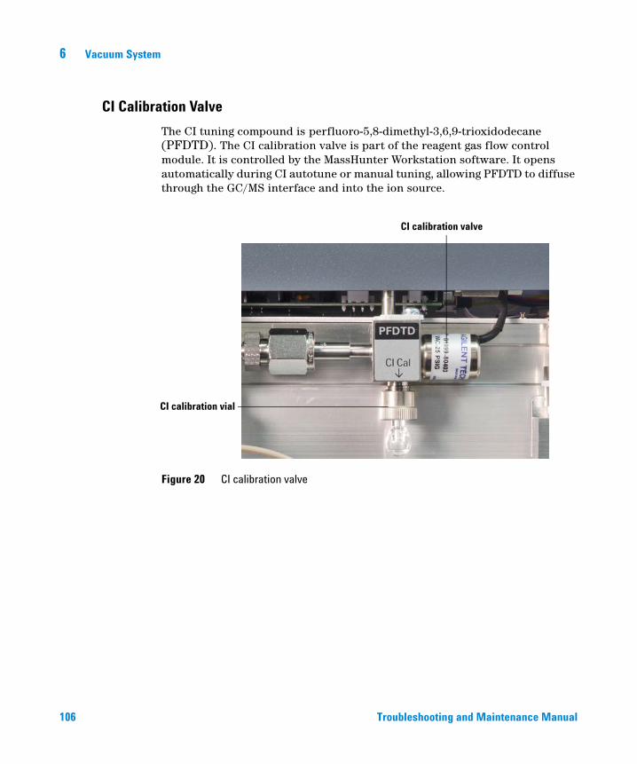
6 Vacuum System
CI Calibration Valve
106
The CI tuning compound is perfluoro-5,8-dimethyl-3,6,9-trioxidodecane (PFDTD). The CI calibration valve is part of the reagent gas flow control module. It is controlled by the MassHunter Workstation software. It opens automatically during CI autotune or manual tuning, allowing PFDTD to diffuse through the GC/MS interface and into the ion source.
Figure 20 CI calibration valve
CI calibration valve
CI calibration vial
Tro
ubleshooting and Maintenance Manual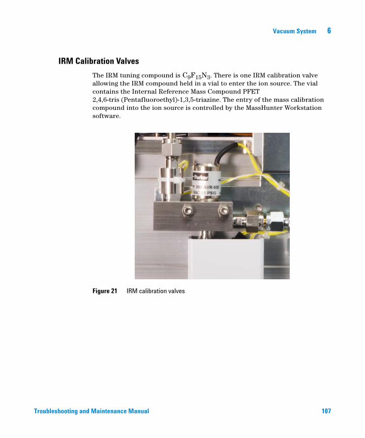
Vacuum System 6
IRM Calibration Valves
Troubleshooting and
The IRM tuning compound is C9F15N3. There is one IRM calibration valve allowing the IRM compound held in a vial to enter the ion source. The vial contains the Internal Reference Mass Compound PFET 2,4,6-tris (Pentafluoroethyl)-1,3,5-triazine. The entry of the mass calibration compound into the ion source is controlled by the MassHunter Workstation software.
Figure 21 IRM calibration valves
Maintenance Manual 107

108
6 Vacuum System
Troubleshooting and Maintenance Manual
Agilent 7200 Accurate-Mass Q-TOF GC/MS System Troubleshooting and Maintenance Manual
7Replacement Parts
To Order Parts 110
Electronics 111
Vacuum System 116
Analyzer 121
RIS Manifold 130
Consumables and Maintenance Supplies 133
This chapter lists parts that can be ordered for use in maintaining your 7200 Accurate-Mass Q-TOF GC/MS System. It includes most of the parts or assemblies in the MS.
Most of the parts listed are not user-replaceable. They are listed here for use by Agilent Technologies service representatives.
109Agilent Technologies
7 Replacement Parts
To Order Parts
110
To order parts for your MS, address the order or inquiry to your local Agilent Technologies office. Supply them with the following information:
• Model and serial number of your MS, located on a label on the lower left side near the front of the instrument.
• Part number(s) of the part(s) needed
• Quantity of each part needed
Some parts are available as rebuilt assemblies
Rebuilt assemblies pass all the same tests and meet all the same specifications as new parts. Rebuilt assemblies can be identified by their part numbers. The first two digits of the second part of the part number are 69 or 89 (such as xxxxx-69xxx or xxxxx-89xxx). Rebuilt assemblies are available on an exchange-only basis. When you return the original part to Agilent Technologies (after you receive the rebuilt assembly) you will receive a credit.
If you cannot find a part you need
If you need a part that is not listed in this chapter, check the Agilent Technologies Analytical Supplies Catalog or the online catalog on the Worldwide Web at http://www.agilent.com/chem. If you still cannot find it, contact your Agilent Technologies service representative or your Agilent Technologies office.
Troubleshooting and Maintenance Manual
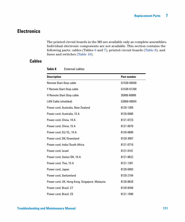
Replacement Parts 7
Electronics
Troubleshooting and
The printed circuit boards in the MS are available only as complete assemblies. Individual electronic components are not available. This section contains the following parts: cables (Tables 6 and 7), printed circuit boards (Table 8), and fuses and switches (Table 10).
Cables
Table 6 External cables
Description Part number
Remote Start-Stop cable G1530-60930
Y Remote Start-Stop cable G1530-61200
H Remote Start-Stop cable 35900-60800
LAN Cable (shielded) G3850-60834
Power cord, Australia, New Zealand 8120-1369
Power cord, Australia, 15 A 8120-6900
Power cord, China, 10 A 8121-0723
Power cord, China, 15 A 8121-0070
Power cord, EU/CL, 16 A 8120-6899
Power cord, DK/Greenland 8120-3997
Power cord, India/South Africa 8121-0710
Power cord, Israel 8121-0161
Power cord, Swiss/DK, 16 A 8121-8622
Power cord, Thai, 15 A 8121-1301
Power cord, Japan 8120-6903
Power cord, Switzerland 8120-2104
Power cord, UK, Hong Kong, Singapore, Malaysia 8120-8620
Power cord, Brazil, C7 8120-8340
Power cord, Brazil, C5 8121-1990
Maintenance Manual 111
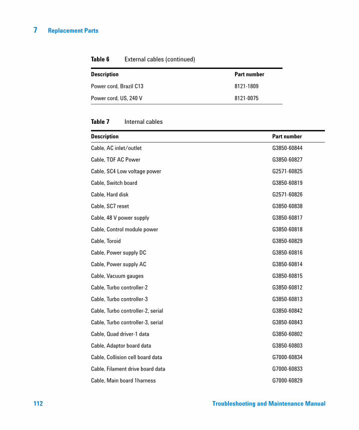
112
7 Replacement Parts
Power cord, Brazil C13 8121-1809
Power cord, US, 240 V 8121-0075
Table 7 Internal cables
Description Part number
Cable, AC inlet/outlet G3850-60844
Cable, TOF AC Power G3850-60827
Cable, SC4 Low voltage power G2571-60825
Cable, Switch board G3850-60819
Cable, Hard disk G2571-60826
Cable, SC7 reset G3850-60838
Cable, 48 V power supply G3850-60817
Cable, Control module power G3850-60818
Cable, Toroid G3850-60829
Cable, Power supply DC G3850-60816
Cable, Power supply AC G3850-60814
Cable, Vacuum gauges G3850-60815
Cable, Turbo controller-2 G3850-60812
Cable, Turbo controller-3 G3850-60813
Cable, Turbo controller-2, serial G3850-60842
Cable, Turbo controller-3, serial G3850-60843
Cable, Quad driver-1 data G3850-60802
Cable, Adaptor board data G3850-60803
Cable, Collision cell board data G7000-60834
Cable, Filament drive board data G7000-60833
Cable, Main board 1harness G7000-60829
Table 6 External cables (continued)
Description Part number
Troubleshooting and Maintenance Manual
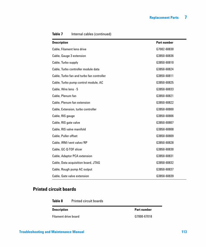
Replacement Parts 7
Troubleshooting and
Cable, Filament lens drive G7002-60830
Cable, Gauge 3 extension G3850-60836
Cable, Turbo supply G3850-60810
Cable, Turbo controller module data G3850-60824
Cable, Turbo fan and turbo fan controller G3850-60811
Cable, Turbo pump control module, AC G3850-60825
Cable, Wire lens - 5 G3850-60833
Cable, Plenum fan G3850-60821
Cable, Plenum fan extension G3850-60822
Cable, Extension, turbo controller G3850-60800
Cable, RIS gauge G3850-60806
Cable, RIS gate valve G3850-60807
Cable, RIS valve manifold G3850-60808
Cable, Puller offset G3850-60809
Cable, IRM/vent valve/RP G3850-60828
Cable, GC-Q-TOF slicer G3850-60830
Cable, Adaptor PCA extension G3850-60831
Cable, Data acquisition board, JTAG G3850-60832
Cable, Rough pump AC output G3850-60837
Cable, Gate valve extension G3850-60839
Table 7 Internal cables (continued)
Description Part number
Printed circuit boards
Table 8 Printed circuit boards
Description Part number
Filament drive board G7000-67018
Maintenance Manual 113
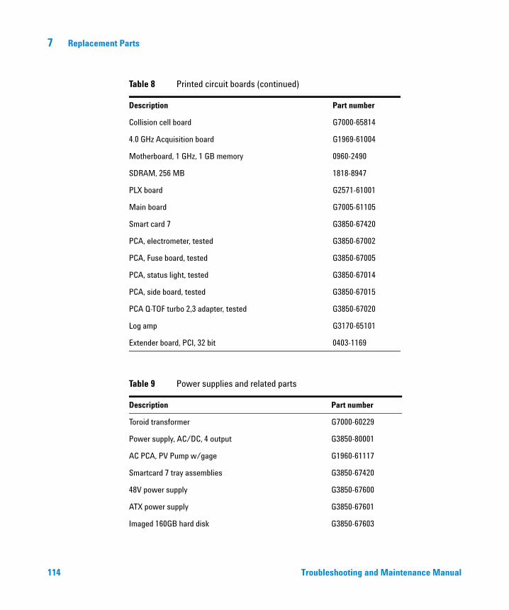
114
7 Replacement Parts
Collision cell board G7000-65814
4.0 GHz Acquisition board G1969-61004
Motherboard, 1 GHz, 1 GB memory 0960-2490
SDRAM, 256 MB 1818-8947
PLX board G2571-61001
Main board G7005-61105
Smart card 7 G3850-67420
PCA, electrometer, tested G3850-67002
PCA, Fuse board, tested G3850-67005
PCA, status light, tested G3850-67014
PCA, side board, tested G3850-67015
PCA Q-TOF turbo 2,3 adapter, tested G3850-67020
Log amp G3170-65101
Extender board, PCI, 32 bit 0403-1169
Table 9 Power supplies and related parts
Description Part number
Toroid transformer G7000-60229
Power supply, AC/DC, 4 output G3850-80001
AC PCA, PV Pump w/gage G1960-61117
Smartcard 7 tray assemblies G3850-67420
48V power supply G3850-67600
ATX power supply G3850-67601
Imaged 160GB hard disk G3850-67603
Table 8 Printed circuit boards (continued)
Description Part number
Troubleshooting and Maintenance Manual
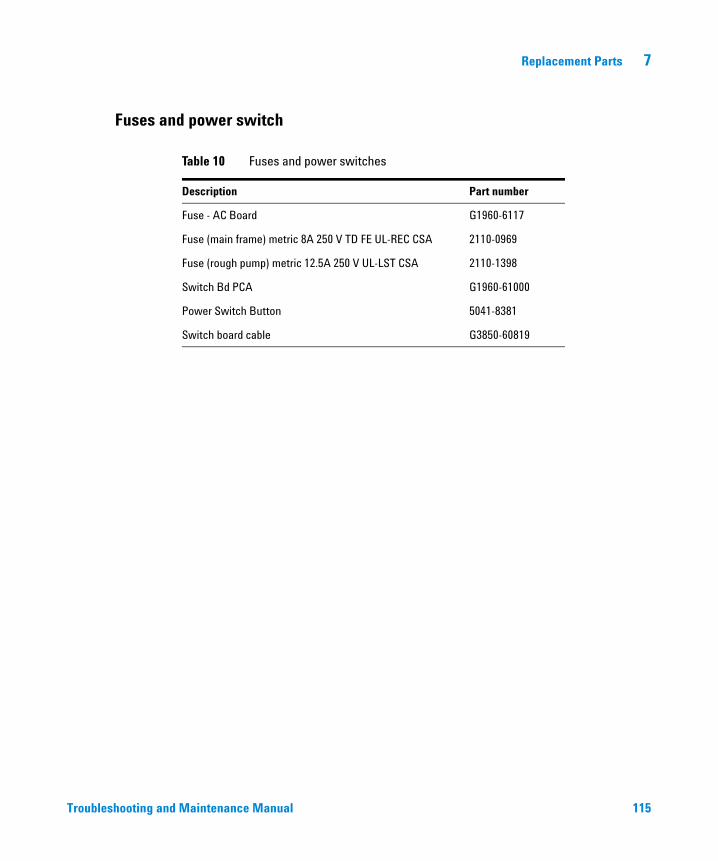
Replacement Parts 7
Fuses and power switch
Troubleshooting and
Table 10 Fuses and power switches
Description Part number
Fuse - AC Board G1960-6117
Fuse (main frame) metric 8A 250 V TD FE UL-REC CSA 2110-0969
Fuse (rough pump) metric 12.5A 250 V UL-LST CSA 2110-1398
Switch Bd PCA G1960-61000
Power Switch Button 5041-8381
Switch board cable G3850-60819
Maintenance Manual 115
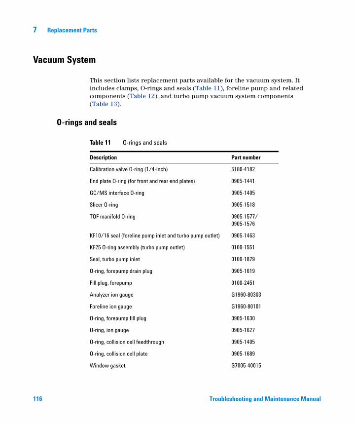
7 Replacement Parts
Vacuum System
116
This section lists replacement parts available for the vacuum system. It includes clamps, O-rings and seals (Table 11), foreline pump and related components (Table 12), and turbo pump vacuum system components (Table 13).
O-rings and seals
Table 11 O-rings and seals
Description Part number
Calibration valve O-ring (1/4-inch) 5180-4182
End plate O-ring (for front and rear end plates) 0905-1441
GC/MS interface O-ring 0905-1405
Slicer O-ring 0905-1518
TOF manifold O-ring 0905-1577/0905-1576
KF10/16 seal (foreline pump inlet and turbo pump outlet) 0905-1463
KF25 O-ring assembly (turbo pump outlet) 0100-1551
Seal, turbo pump inlet 0100-1879
O-ring, forepump drain plug 0905-1619
Fill plug, forepump 0100-2451
Analyzer ion gauge G1960-80303
Foreline ion gauge G1960-80101
O-ring, forepump fill plug 0905-1630
O-ring, ion gauge 0905-1627
O-ring, collision cell feedthrough 0905-1405
O-ring, collision cell plate 0905-1689
Window gasket G7005-40015
Troubleshooting and Maintenance Manual
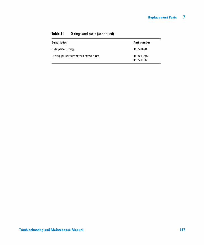
Replacement Parts 7
Troubleshooting and
Side plate O-ring 0905-1690
O-ring, pulser/detector access plate 0905-1735/0905-1736
Table 11 O-rings and seals (continued)
Description Part number
Maintenance Manual 117
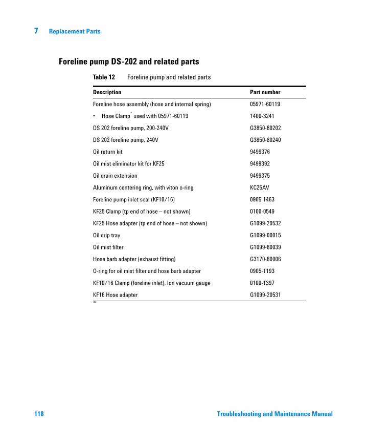
7 Replacement Parts
Foreline pump DS-202 and related parts
118
Table 12 Foreline pump and related parts
Description Part number
Foreline hose assembly (hose and internal spring) 05971-60119
• Hose Clamp* used with 05971-60119
*
1400-3241
DS 202 foreline pump, 200-240V G3850-80202
DS 202 foreline pump, 240V G3850-80240
Oil return kit 9499376
Oil mist eliminator kit for KF25 9499392
Oil drain extension 9499375
Aluminum centering ring, with viton o-ring KC25AV
Foreline pump inlet seal (KF10/16) 0905-1463
KF25 Clamp (tp end of hose – not shown) 0100-0549
KF25 Hose adapter (tp end of hose – not shown) G1099-20532
Oil drip tray G1099-00015
Oil mist filter G1099-80039
Hose barb adapter (exhaust fitting) G3170-80006
O-ring for oil mist filter and hose barb adapter 0905-1193
KF10/16 Clamp (foreline inlet), Ion vacuum gauge 0100-1397
KF16 Hose adapter G1099-20531
Troubleshooting and Maintenance Manual
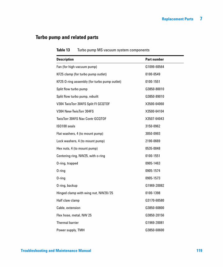
Replacement Parts 7
Turbo pump and related parts
Troubleshooting and
Table 13 Turbo pump MS vacuum system components
Description Part number
Fan (for high-vacuum pump) G1099-60564
KF25 clamp (for turbo pump outlet) 0100-0549
KF25 O-ring assembly (for turbo pump outlet) 0100-1551
Split flow turbo pump G3850-80010
Split flow turbo pump, rebuilt G3850-89010
V304 TwisTorr 304FS Split FI GCQTOF X3500-64060
V304 New-TwisTorr 304FS X3500-64104
TwisTorr 304FS Nav Contr GCQTOF X3507-64043
ISO100 seals 3150-0962
Flat washers, 4 (to mount pump) 3050-0993
Lock washers, 4 (to mount pump) 2190-0669
Hex nuts, 4 (to mount pump) 0535-0048
Centering ring, NW25, with o-ring 0100-1551
O-ring, trapped 0905-1463
O-ring 0905-1574
O-ring 0905-1573
O-ring, backup G1969-20082
Hinged clamp with wing nut, NW20/25 0100-1398
Half claw clamp G3170-60580
Cable, extension G3850-60800
Flex hose, metal, NW 25 G3850-20156
Thermal barrier G1969-20081
Power supply, TMH G3850-60600
Maintenance Manual 119
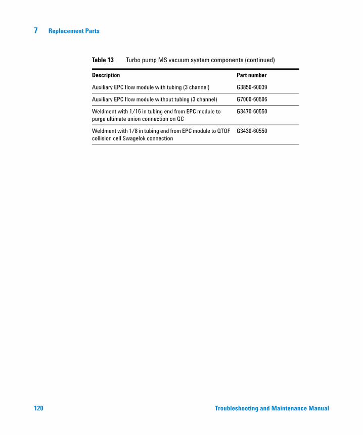
120
7 Replacement Parts
Auxiliary EPC flow module with tubing (3 channel) G3850-60039
Auxiliary EPC flow module without tubing (3 channel) G7000-60506
Weldment with 1/16 in tubing end from EPC module to purge ultimate union connection on GC
G3470-60550
Weldment with 1/8 in tubing end from EPC module to QTOF collision cell Swagelok connection
G3430-60550
Table 13 Turbo pump MS vacuum system components (continued)
Description Part number
Troubleshooting and Maintenance Manual
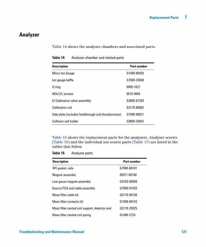
Replacement Parts 7
Analyzer
Troubleshooting and
Table 14 shows the analyzer chambers and associated parts.
Table 15 shows the replacement parts for the analyzers. Analyzer screws (Table 16) and the individual ion source parts (Table 17) are listed in the tables that follow.
Table 14 Analyzer chamber and related parts
Description Part number
Micro Ion Gauge G1960-80303
Ion gauge baffle G7000-20049
O-ring 0905-1627
M3x12L screws 0515-0664
EI Calibration valve assembly G3850-67204
Calibration vial G3170-80002
Side plate (includes feedthrough and thumbscrews) G7000-60021
Collision cell holder G3850-20042
Table 15 Analyzer parts
Description Part number
RFI gasket, side G7000-80101
Magnet assembly 05971-60160
Low gauss magnet assembly G3163-60560
Source PCA and cable assembly G7005-67425
Mass filter cable kit G3170-60130
Mass filter contacts (4) G1099-60142
Mass filter canted coil support, detector end G3170-20025
Mass filter canted coil spring G1460-2724
Maintenance Manual 121
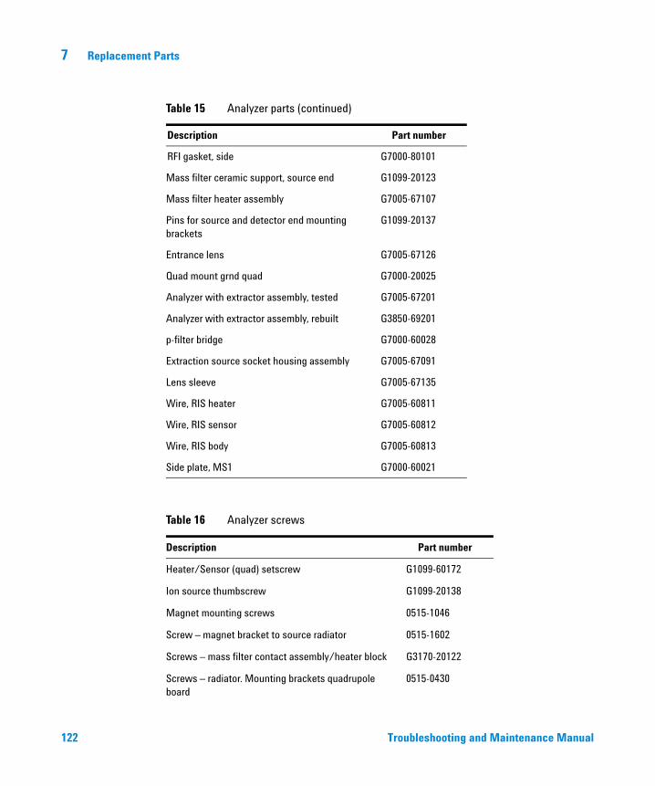
122
7 Replacement Parts
Mass filter ceramic support, source end G1099-20123
Mass filter heater assembly G7005-67107
Pins for source and detector end mounting brackets
G1099-20137
Entrance lens G7005-67126
Quad mount grnd quad G7000-20025
Analyzer with extractor assembly, tested G7005-67201
Analyzer with extractor assembly, rebuilt G3850-69201
p-filter bridge G7000-60028
Extraction source socket housing assembly G7005-67091
Lens sleeve G7005-67135
Wire, RIS heater G7005-60811
Wire, RIS sensor G7005-60812
Wire, RIS body G7005-60813
Side plate, MS1 G7000-60021
Table 16 Analyzer screws
Description Part number
Heater/Sensor (quad) setscrew G1099-60172
Ion source thumbscrew G1099-20138
Magnet mounting screws 0515-1046
Screw – magnet bracket to source radiator 0515-1602
Screws – mass filter contact assembly/heater block G3170-20122
Screws – radiator. Mounting brackets quadrupole board
0515-0430
Table 15 Analyzer parts (continued)
Description Part number
RFI gasket, side G7000-80101
Troubleshooting and Maintenance Manual
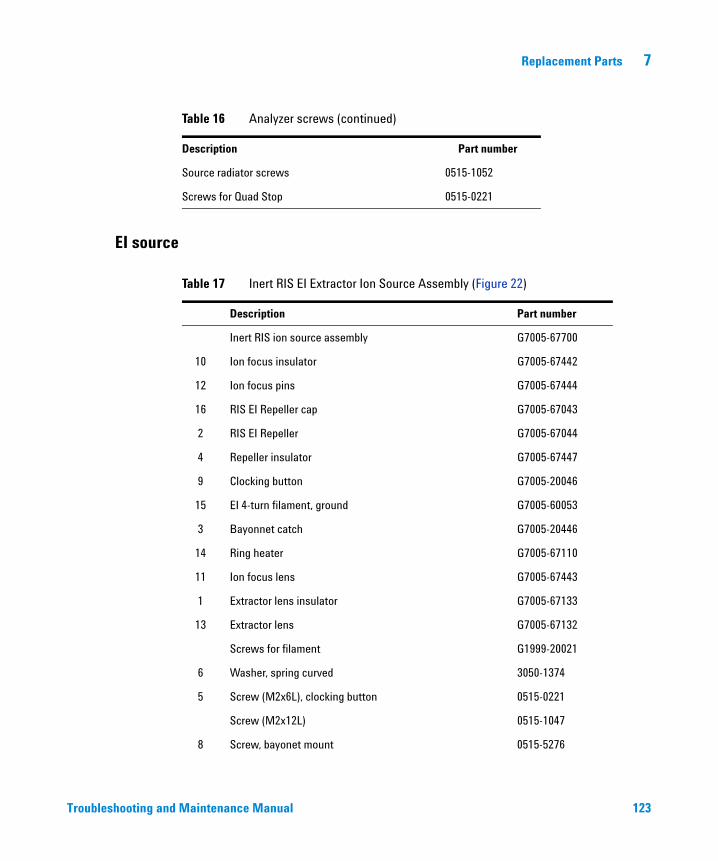
Replacement Parts 7
Troubleshooting and
Source radiator screws 0515-1052
Screws for Quad Stop 0515-0221
Table 16 Analyzer screws (continued)
Description Part number
EI source
Table 17 Inert RIS EI Extractor Ion Source Assembly (Figure 22)
Description Part number
Inert RIS ion source assembly G7005-67700
10 Ion focus insulator G7005-67442
12 Ion focus pins G7005-67444
16 RIS EI Repeller cap G7005-67043
2 RIS EI Repeller G7005-67044
4 Repeller insulator G7005-67447
9 Clocking button G7005-20046
15 EI 4-turn filament, ground G7005-60053
3 Bayonnet catch G7005-20446
14 Ring heater G7005-67110
11 Ion focus lens G7005-67443
1 Extractor lens insulator G7005-67133
13 Extractor lens G7005-67132
Screws for filament G1999-20021
6 Washer, spring curved 3050-1374
5 Screw (M2x6L), clocking button 0515-0221
Screw (M2x12L) 0515-1047
8 Screw, bayonet mount 0515-5276
Maintenance Manual 123
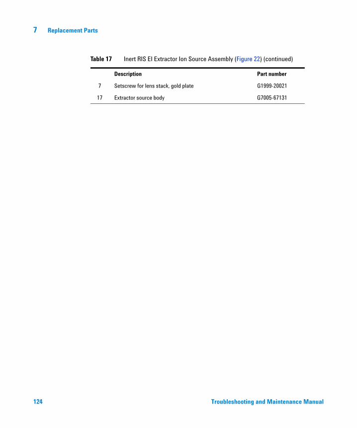
124
7 Replacement Parts
7 Setscrew for lens stack, gold plate G1999-20021
17 Extractor source body G7005-67131
Table 17 Inert RIS EI Extractor Ion Source Assembly (Figure 22) (continued)
Description Part number
Troubleshooting and Maintenance Manual
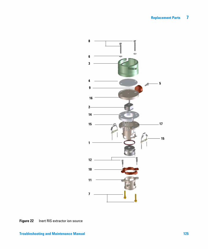
Replacement Parts 7
Figure 22 Inert RIS extractor ion source
8
6
4
3
5
16
2
15
14
17
1
12
10
11
7
9
15
Troubleshooting and Maintenance Manual
125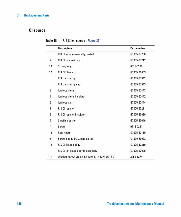
7 Replacement Parts
CI source
126
Table 18 RIS CI ion source (Figure 23)
Description Part number
RIS CI source assembly, tested G7005-67750
2 RIS CI bayonet catch G7005-67212
10 Screw, long 0515-5276
12 RIS CI filament G7005-80053
RIS transfer tip G7005-67542
RIS transfer tip cap G7005-67543
8 Ion focus lens G7005-67443
7 Ion focus lens insulator G7005-67442
9 Ion focus pin G7005-67444
1 RIS CI repeller G7005-67211
3 RIS CI repeller insulator G7005-20030
6 Clocking button G7005-20046
4 Screw 0515-0221
13 Ring heater G7005-67110
5 Screw-set, M3x3L, gold plated G1999-20022
14 RIS CI Source body G7005-67210
RIS CI ion source bottle assembly G7005-67005
11 Washer-spr CRVD 1.6 1.8-MM-ID, 4-MM-OD, SS 3050-1374
Troubleshooting and Maintenance Manual
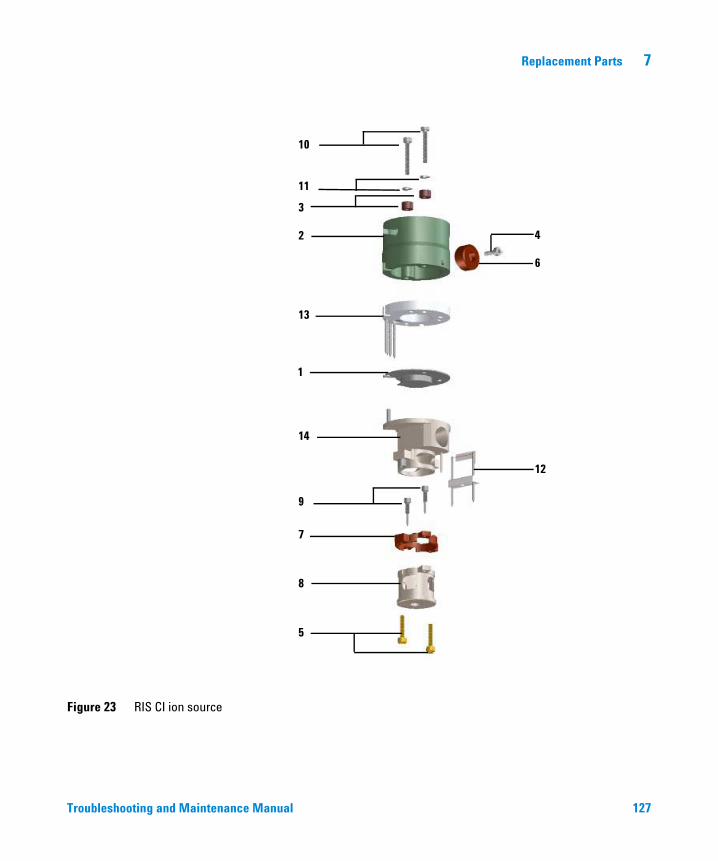
Replacement Parts 7
Figure 23 RIS CI ion source
10
11
3
2 4
6
13
1
14
12
9
7
8
5
Troubleshooting and Maintenance Manua
l 127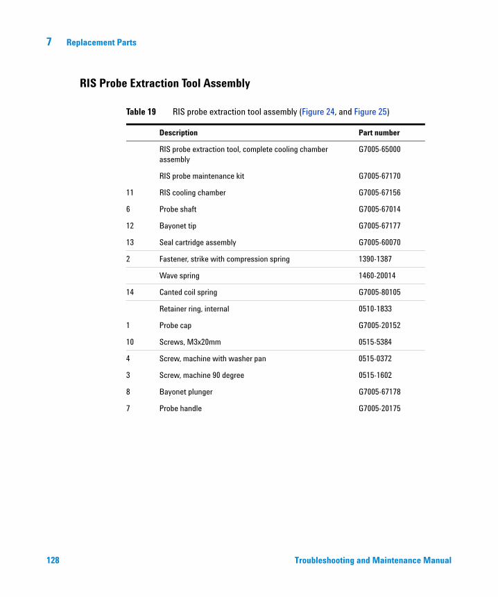
7 Replacement Parts
RIS Probe Extraction Tool Assembly
128
Table 19 RIS probe extraction tool assembly (Figure 24, and Figure 25)
Description Part number
RIS probe extraction tool, complete cooling chamber assembly
G7005-65000
RIS probe maintenance kit G7005-67170
11 RIS cooling chamber G7005-67156
6 Probe shaft G7005-67014
12 Bayonet tip G7005-67177
13 Seal cartridge assembly G7005-60070
2 Fastener, strike with compression spring 1390-1387
Wave spring 1460-20014
14 Canted coil spring G7005-80105
Retainer ring, internal 0510-1833
1 Probe cap G7005-20152
10 Screws, M3x20mm 0515-5384
4 Screw, machine with washer pan 0515-0372
3 Screw, machine 90 degree 0515-1602
8 Bayonet plunger G7005-67178
7 Probe handle G7005-20175
Troubleshooting and Maintenance Manual
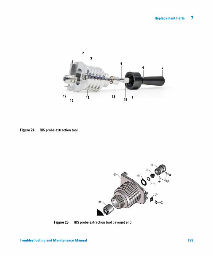
Replacement Parts 7
Figure 24 RIS probe extraction tool
4 76
115
1311
2
3
1210
Troubleshooting and
Figure 25 RIS probe extraction tool bayonet end
Maintenance Manual
129
7 Replacement Parts
RIS Manifold
130
Table 20 RIS Manifold
Description Part number
RIS manifold assembly G7005-67100
Gate valve extension cable G3850-60839
Gate valve G7005-67010
Restrictor assembly G7005-67015
RIS convection vacuum gauge assembly G7005-67158
Gauge adapter G7005-20165
Frame G7005-00001
Gasket G7005-40015
Inner window G7005-20552
RIS control valve G7005-60009
RIS rear manifold support assembly G7005-67159
RIS probe manifold support assembly G7005-67160
Dust cover G7005-20155
Relief valve, 1psi 0101-1457
Hinge bushing G7005-20157
Catch housing G7005-20011
Catch knob G7005-20010
Catch pin G7005-20009
RIS front manifold G7005-20158
Screw, pan with washer, T10 M3x10MM-lg 0515-0666
O-ring, 0.239 inch id, 0.07 in xsect diameter 0905-1014
O-ring, 2.239 inch id, 0.07 in xsect diameter 0905-1131
Troubleshooting and Maintenance Manual
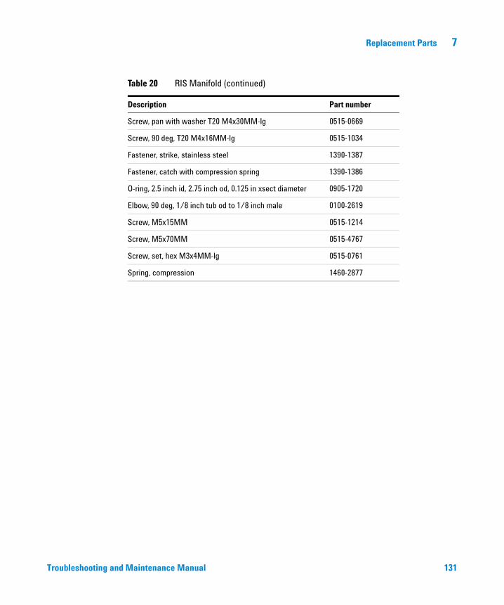
Replacement Parts 7
Troubleshooting and
Screw, pan with washer T20 M4x30MM-lg 0515-0669
Screw, 90 deg, T20 M4x16MM-lg 0515-1034
Fastener, strike, stainless steel 1390-1387
Fastener, catch with compression spring 1390-1386
O-ring, 2.5 inch id, 2.75 inch od, 0.125 in xsect diameter 0905-1720
Elbow, 90 deg, 1/8 inch tub od to 1/8 inch male 0100-2619
Screw, M5x15MM 0515-1214
Screw, M5x70MM 0515-4767
Screw, set, hex M3x4MM-lg 0515-0761
Spring, compression 1460-2877
Table 20 RIS Manifold (continued)
Description Part number
Maintenance Manual 131
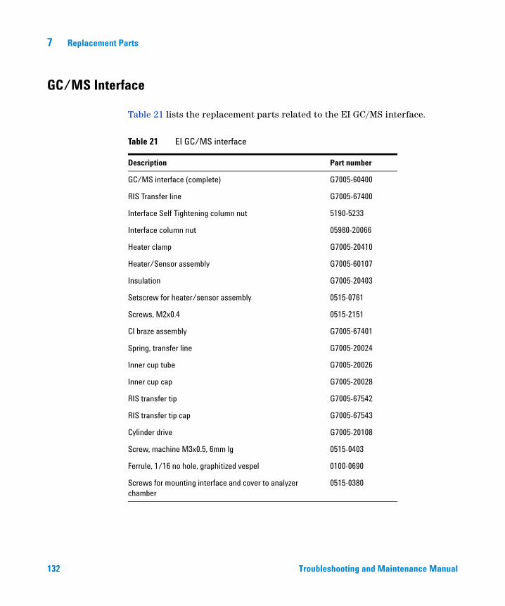
7 Replacement Parts
GC/MS Interface
132
Table 21 lists the replacement parts related to the EI GC/MS interface.
Table 21 EI GC/MS interface
Description Part number
GC/MS interface (complete) G7005-60400
RIS Transfer line G7005-67400
Interface Self Tightening column nut 5190-5233
Interface column nut 05980-20066
Heater clamp G7005-20410
Heater/Sensor assembly G7005-60107
Insulation G7005-20403
Setscrew for heater/sensor assembly 0515-0761
Screws, M2x0.4 0515-2151
CI braze assembly G7005-67401
Spring, transfer line G7005-20024
Inner cup tube G7005-20026
Inner cup cap G7005-20028
RIS transfer tip G7005-67542
RIS transfer tip cap G7005-67543
Cylinder drive G7005-20108
Screw, machine M3x0.5, 6mm lg 0515-0403
Ferrule, 1/16 no hole, graphitized vespel 0100-0690
Screws for mounting interface and cover to analyzer chamber
0515-0380
Troubleshooting and Maintenance Manual
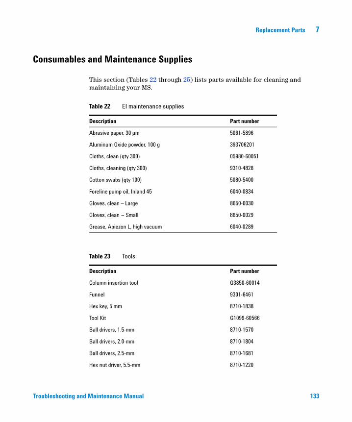
Replacement Parts 7
Consumables and Maintenance Supplies
Troubleshooting and
This section (Tables 22 through 25) lists parts available for cleaning and maintaining your MS.
Table 22 EI maintenance supplies
Description Part number
Abrasive paper, 30 µm 5061-5896
Aluminum Oxide powder, 100 g 393706201
Cloths, clean (qty 300) 05980-60051
Cloths, cleaning (qty 300) 9310-4828
Cotton swabs (qty 100) 5080-5400
Foreline pump oil, Inland 45 6040-0834
Gloves, clean – Large 8650-0030
Gloves, clean – Small 8650-0029
Grease, Apiezon L, high vacuum 6040-0289
Table 23 Tools
Description Part number
Column insertion tool G3850-60014
Funnel 9301-6461
Hex key, 5 mm 8710-1838
Tool Kit G1099-60566
Ball drivers, 1.5-mm 8710-1570
Ball drivers, 2.0-mm 8710-1804
Ball drivers, 2.5-mm 8710-1681
Hex nut driver, 5.5-mm 8710-1220
Maintenance Manual 133
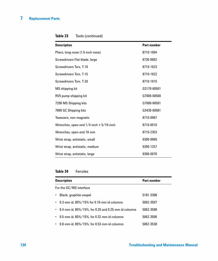
134
7 Replacement Parts
Pliers, long-nose (1.5-inch nose) 8710-1094
Screwdrivers Flat-blade, large 8730-0002
Screwdrivers Torx, T-10 8710-1623
Screwdrivers Torx, T-15 8710-1622
Screwdrivers Torx. T-20 8710-1615
MS shipping kit G3170-60501
RV5 pump shipping kit G7000-60500
7200 MS Shipping kits G7000-60501
7890 GC Shipping kits G3430-60581
Tweezers, non-magnetic 8710-0907
Wrenches, open-end 1/4-inch × 5/16-inch 8710-0510
Wrenches, open-end 10-mm 8710-2353
Wrist strap, antistatic, small 9300-0969
Wrist strap, antistatic, medium 9300-1257
Wrist strap, antistatic, large 9300-0970
Table 24 Ferrules
Description Part number
For the GC/MS interface
• Blank, graphite-vespel 5181-3308
• 0.3-mm id, 85%/15% for 0.10-mm id columns 5062-3507
• 0.4-mm id, 85%/15%, for 0.20 and 0.25-mm id columns 5062-3508
• 0.5-mm id, 85%/15%, for 0.32-mm id columns 5062-3506
• 0.8-mm id, 85%/15%, for 0.53-mm id columns 5062-3538
Table 23 Tools (continued)
Description Part number
Troubleshooting and Maintenance Manual
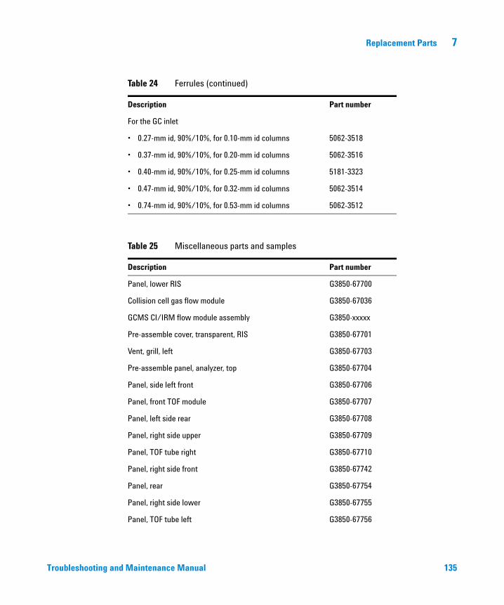
Replacement Parts 7
Troubleshooting and
For the GC inlet
• 0.27-mm id, 90%/10%, for 0.10-mm id columns 5062-3518
• 0.37-mm id, 90%/10%, for 0.20-mm id columns 5062-3516
• 0.40-mm id, 90%/10%, for 0.25-mm id columns 5181-3323
• 0.47-mm id, 90%/10%, for 0.32-mm id columns 5062-3514
• 0.74-mm id, 90%/10%, for 0.53-mm id columns 5062-3512
Table 25 Miscellaneous parts and samples
Description Part number
Panel, lower RIS G3850-67700
Collision cell gas flow module G3850-67036
GCMS CI/IRM flow module assembly G3850-xxxxx
Pre-assemble cover, transparent, RIS G3850-67701
Vent, grill, left G3850-67703
Pre-assemble panel, analyzer, top G3850-67704
Panel, side left front G3850-67706
Panel, front TOF module G3850-67707
Panel, left side rear G3850-67708
Panel, right side upper G3850-67709
Panel, TOF tube right G3850-67710
Panel, right side front G3850-67742
Panel, rear G3850-67754
Panel, right side lower G3850-67755
Panel, TOF tube left G3850-67756
Table 24 Ferrules (continued)
Description Part number
Maintenance Manual 135

136
7 Replacement Parts
Subpanel, rear upper G3850-67758
Panel bracket, right RIS G3850-67761
Panel, upper RIS G3850-67762
Octafluoronaphthalene, OFN, 100 fg/µL 5188-5348
PFTBA, 10 gram 8500-0656
Benzophenone, 100 pg/µL 8500-5440
PFTBA sample kit 05971-60571
Foreline pump tray G1099-00015
Rough pump oil pan G1946-00034
Eval A, hydrocarbons 05971-60045
Micro-Ion gauge electronics G3170-89001
J20’ 1/8-inch id stainless steel 7157-0210
Wipes (qty 300) 9310-4828
Swagelok ferrule, front, 1/8-inch, 10/package 5180-4110
Swagelok ferrule, rear, 1/8-inch, 10/package 5180-4116
Swagelok nut, for 1/8-inch fitting, 10/package 5180-4104
Swagelok nut and ferrules, 10 set/package 5080-8751
Tubing cutter for SS tubing 8710-1709
Tubing cutter replacement blades 8710-1710
Table 25 Miscellaneous parts and samples (continued)
Description Part number
Troubleshooting and Maintenance Manual


Agilent Technologies
© Agilent Technologies, Inc.
Printed in USA, August 2014
*G3850-90009*
G3850-90009