agilent 16900 series logic analysis system mainframes · agilent 16900 series logic analysis system...
TRANSCRIPT
Agilent 16900 Series Logic Analysis System MainframesData Sheet
Conquer your toughest digital debug problems while staying within your budget
The Agilent 16900 Series modu-lar logic analysis mainframesdeliver the performance you needto conquer your toughest digitaldebug problems. You get accurateand reliable measurements fortoday’s complex circuits, withexpandability and performanceheadroom to cover future tech-nology trends. In addition, theintuitive user interface gives youthe ultimate in productivity with-out sacrificing performance orcapability. You get performanceand intuitive usability at a priceyou can afford.
Expand your system as your needs evolve
Expandability is the key to thelong-term value of the Agilent16900 Series logic analysis sys-tems. Purchase the capability youneed now, then expand as yourneeds evolve. Maximize main-frame usage by operating themseparately, then connecting themtogether for complex, high-chan-nel-count, multiple-bus applica-tions. Whether you are doing sim-ple hardware debug, real-timeanalysis of instruction execution,hardware/software integration,signal-quality analysis or complexsystem validation, you have a sys-tem that meets each of your long-term digital measurement needs.
Spend more time designing and lesstime learning how to use your tools
If you want to focus on solvingyour digital debug problems, youneed to be able to quickly masteryour debug tools. The 16900Series logic analysis mainframeslet you set up measurements easi-ly and navigate through your dataquickly with an intuitive userinterface and familiarity ofWindows® XP Professional.
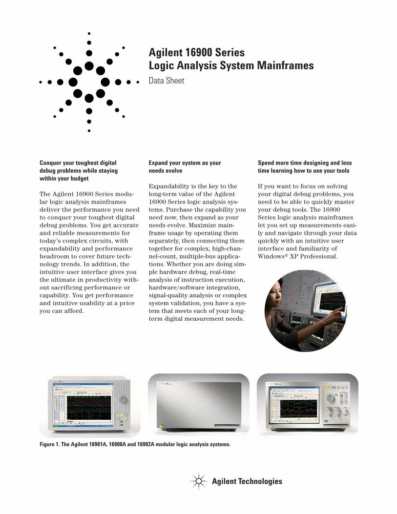
Figure 1. The Agilent 16901A, 16900A and 16902A modular logic analysis systems.
The flexibility you need to debug yourdesign your way
Increase your productivity with a variety of operating modes thatmaximize your analyzer’s usage.Whether you work alone at abench or with team members distributed around the world, the 16900 Series provides a usemodel that easily integrates intoyour debug environment.
Work at your bench — Operatethe analyzer via touch screen,mouse or keyboard.
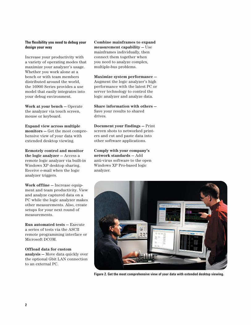
Expand view across multiplemonitors — Get the most compre-hensive view of your data withextended desktop viewing.
Remotely control and monitorthe logic analyzer — Access aremote logic analyzer via built-inWindows XP desktop sharing.Receive e-mail when the logicanalyzer triggers.
Work offline — Increase equip-ment and team productivity. Viewand analyze captured data on aPC while the logic analyzer makesother measurements. Also, createsetups for your next round ofmeasurements.
Run automated tests — Execute a series of tests via the ASCIIremote programming interface orMicrosoft DCOM.
Offload data for custom analysis — Move data quickly overthe optional Gbit LAN connectionto an external PC.
Figure 2. Get the most comprehensive view of your data with extended desktop viewing.
Combine mainframes to expandmeasurement capability — Usemainframes individually, thenconnect them together when you need to analyze complex,multiple-bus problems.
Maximize system performance —Augment the logic analyzer’s highperformance with the latest PC orserver technology to control thelogic analyzer and analyze data.
Share information with others —Save your results to shareddrives.
Document your findings — Printscreen shots to networked print-ers and cut and paste data intoother software applications.
Comply with your company’snetwork standards — Add anti-virus software to the openWindows XP Pro-based logic analyzer.
2
16900 Series mainframe — the poweryou need at a price you can afford
The mainframe you select is thefoundation of your system. TheAgilent 16900 Series includes arange of powerful logic analysismainframes that deliver the per-formance you need at a price youcan afford. You get accurate andreliable measurements, for today’scomplex systems, plus expandabili-ty and performance headroom tocover future technology trends.
Key things to consider when selectinga 16900 Series mainframe:
• Number of module slots —Determine the number of meas-urement modules required foryour specific measurement need.Also consider having additionalslots for future needs.
• Multiframe Pro — 16900 Seriesmainframes can always be usedas a standalone unit. In someinstances your channel needsmay surpass a single mainframe.Multiframe Pro allows you to connect multiple frames into onemeasurement system with a single interface control.
• Display and resolution — Ifyou prefer to operate the ana-lyzer directly from the frontpanel, select a mainframe with a large, built-in touch display. All 16900 Series mainframes can also be usedwith external monitors.
• PCI expansion slots —Customize your logic analyzerperipherals by adding PCI cardsfor a specific capability like mul-tiple monitor video.
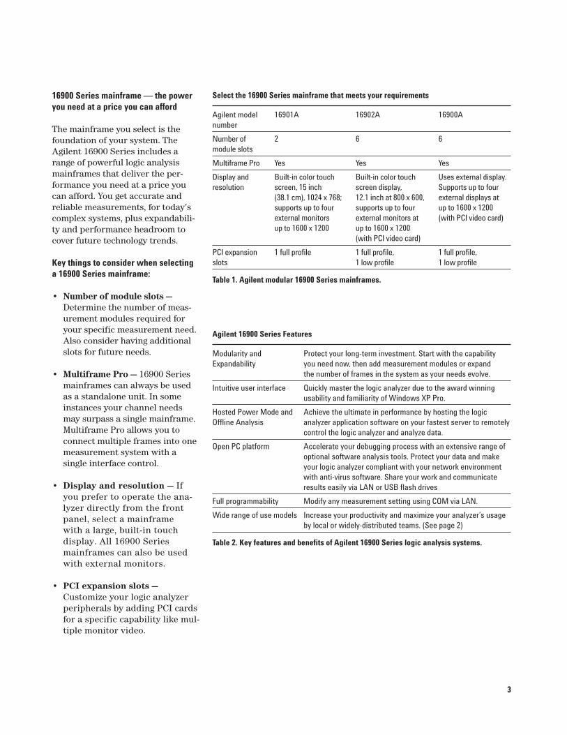
Agilent 16900 Series Features
Modularity and Protect your long-term investment. Start with the capability Expandability you need now, then add measurement modules or expand
the number of frames in the system as your needs evolve.
Intuitive user interface Quickly master the logic analyzer due to the award winningusability and familiarity of Windows XP Pro.
Hosted Power Mode and Achieve the ultimate in performance by hosting the logicOffline Analysis analyzer application software on your fastest server to remotely
control the logic analyzer and analyze data.
Open PC platform Accelerate your debugging process with an extensive range ofoptional software analysis tools. Protect your data and makeyour logic analyzer compliant with your network environmentwith anti-virus software. Share your work and communicateresults easily via LAN or USB flash drives
Full programmability Modify any measurement setting using COM via LAN.
Wide range of use models Increase your productivity and maximize your analyzer’s usage by local or widely-distributed teams. (See page 2)
Table 2. Key features and benefits of Agilent 16900 Series logic analysis systems.
Select the 16900 Series mainframe that meets your requirements
Agilent model 16901A 16902A 16900A number
Number of 2 6 6module slots
Multiframe Pro Yes Yes Yes
Display and Built-in color touch Built-in color touch Uses external display.resolution screen, 15 inch screen display, Supports up to four
(38.1 cm), 1024 x 768; 12.1 inch at 800 x 600, external displays atsupports up to four supports up to four up to 1600 x 1200external monitors external monitors at (with PCI video card)up to 1600 x 1200 up to 1600 x 1200
(with PCI video card)
PCI expansion 1 full profile 1 full profile, 1 full profile,slots 1 low profile 1 low profile
Table 1. Agilent modular 16900 Series mainframes.
3
Measurement Module SupportThe 16900 Series supports thefollowing measurement modules:
Timing/State Modules• 16951B• 16950B• 16950A• 16910A, 16911A• 16760A• 16753A, 16754A, 16755A,
16756A• 16750A/B, 16751A/B,
16752A/B• 16740A, 16741A, 16742A
Pattern Generator Module• 16720A
Modular expandability protects yourlong-term investment
Configure a custom logic analysis system with analyzer modules to fit your performance and price needs. Protect yourinvestment by upgrading memory depths or state speeds as your needs change.
Figure 4. Modularity provides configuration flexibility to meetyour measurement needs—now and in the future.
Figure 3. Combine multiple acquisitionmodules when you need to measure acrossmany channels.
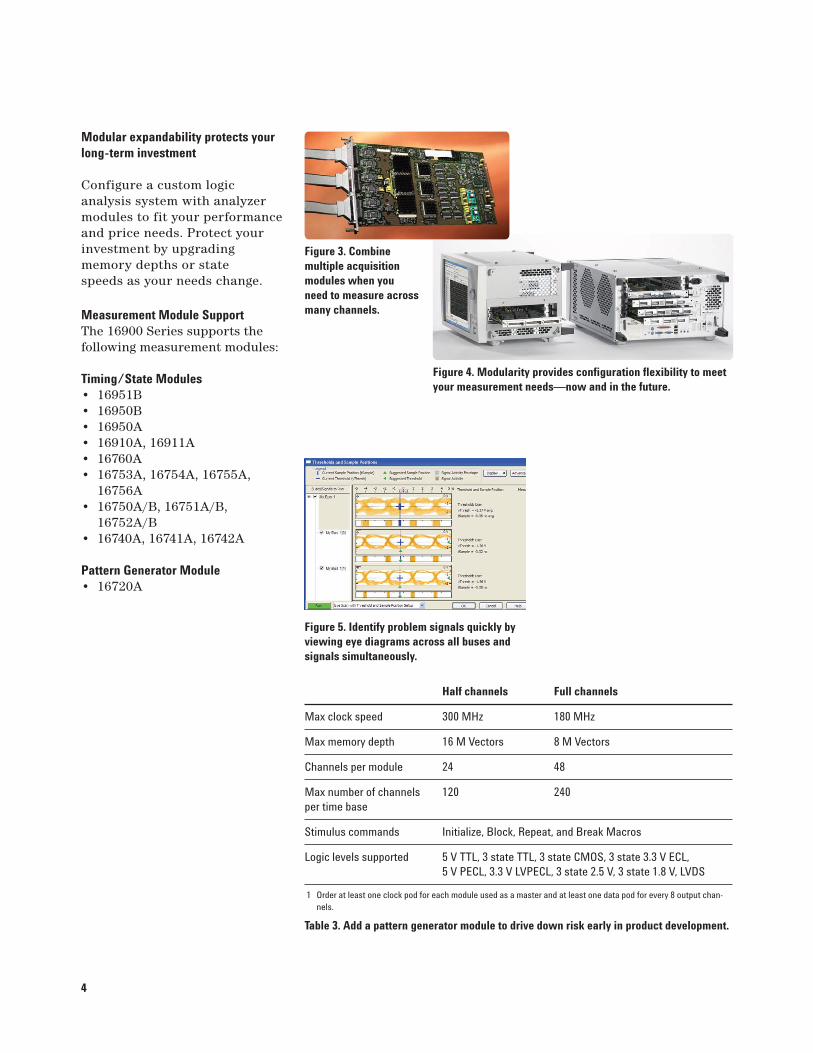
Figure 5. Identify problem signals quickly byviewing eye diagrams across all buses andsignals simultaneously.
Half channels Full channels
Max clock speed 300 MHz 180 MHz
Max memory depth 16 M Vectors 8 M Vectors
Channels per module 24 48
Max number of channels 120 240per time base
Stimulus commands Initialize, Block, Repeat, and Break Macros
Logic levels supported 5 V TTL, 3 state TTL, 3 state CMOS, 3 state 3.3 V ECL, 5 V PECL, 3.3 V LVPECL, 3 state 2.5 V, 3 state 1.8 V, LVDS
1 Order at least one clock pod for each module used as a master and at least one data pod for every 8 output chan-nels.
Table 3. Add a pattern generator module to drive down risk early in product development.
4
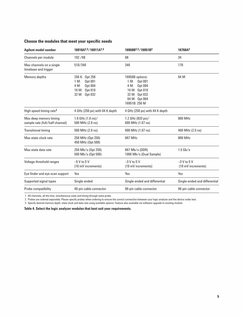
Choose the modules that meet your specific needs
Agilent model number 16910A2,3/16911A2,3 16950B2,3/16951B2 16760A2
Channels per module 102 /68 68 34
Max channels on a single 510/340 340 170timebase and trigger
Memory depths 256 K: Opt 256 16950B options: 64 M1 M: Opt 001 1 M: Opt 0014 M: Opt 004 4 M: Opt 00416 M: Opt 016 16 M: Opt 01632 M: Opt 032 32 M: Opt 032
64 M: Opt 06416951B: 256 M
High speed timing rate1 4 GHz (250 ps) with 64 K depth 4 GHz (250 ps) with 64 K depth
Max deep memory timing 1.0 GHz (1.0 ns)/ 1.2 GHz (833 ps)/ 800 MHzsample rate (full/half channel) 500 MHz (2.0 ns) 600 MHz (1.67 ns)
Transitional timing 500 MHz (2.0 ns) 600 MHz (1.67 ns) 400 MHz (2.5 ns)
Max state clock rate 250 MHz (Opt 250) 667 MHz 800 MHz450 MHz (Opt 500)
Max state data rate 250 Mb/s (Opt 250) 667 Mb/s (DDR) 1.5 Gb/s500 Mb/s (Opt 500) 1066 Mb/s (Dual Sample)
Voltage threshold ranges –5 V to 5 V –3 V to 5 V –3 V to 5 V(10 mV increments) (10 mV increments) (10 mV increments)
Eye finder and eye scan support Yes Yes Yes
Supported signal types Single-ended Single-ended and differential Single-ended and differential
Probe compatibility 40-pin cable connector 90-pin cable connector 90-pin cable connector
1 All channels, all the time, simultaneous state and timing through same probe.2 Probes are ordered separately. Please specify probes when ordering to ensure the correct connection between your logic analyzer and the device under test. 3 Specify desired memory depth, state clock and data rate using available options. Feature also available via software upgrade to existing module.
Table 4. Select the logic analyzer modules that best suit your requirements.
5
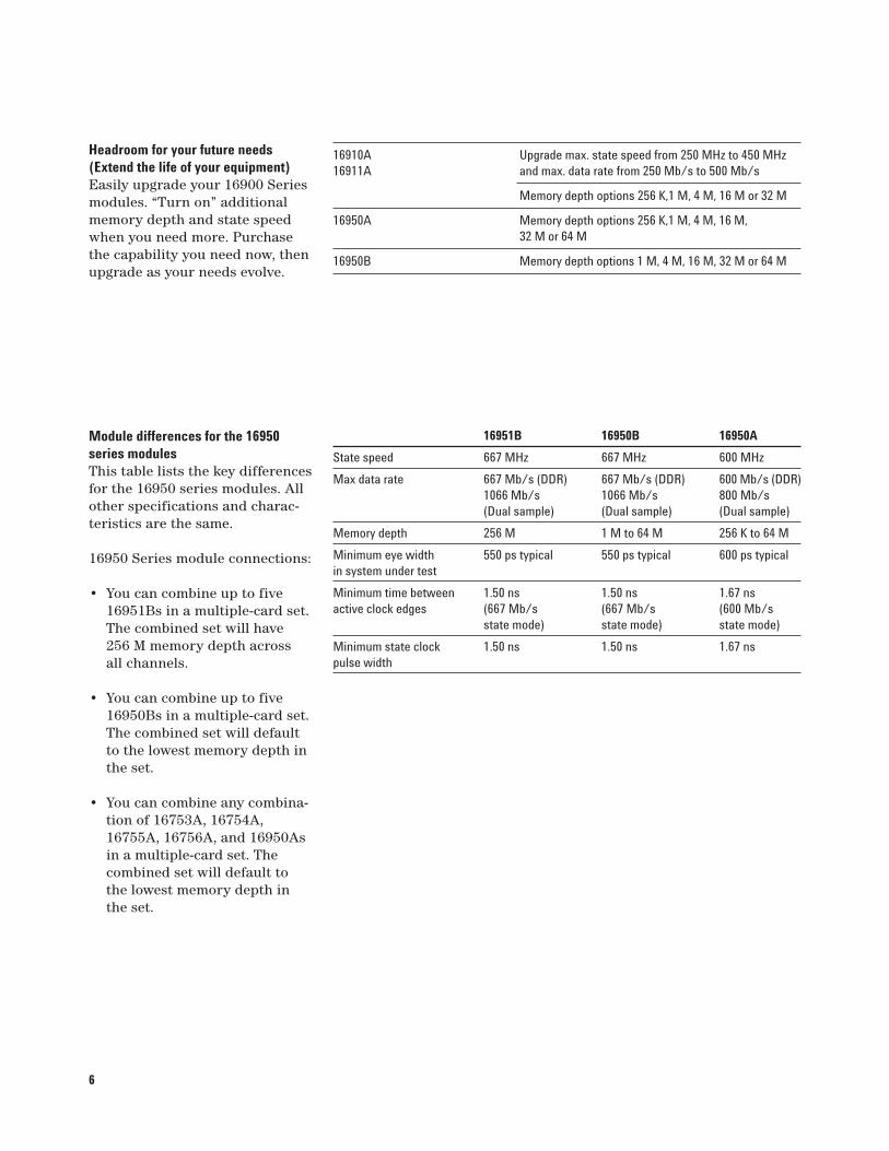
16910A Upgrade max. state speed from 250 MHz to 450 MHz16911A and max. data rate from 250 Mb/s to 500 Mb/s
Memory depth options 256 K,1 M, 4 M, 16 M or 32 M
16950A Memory depth options 256 K,1 M, 4 M, 16 M, 32 M or 64 M
16950B Memory depth options 1 M, 4 M, 16 M, 32 M or 64 M
6
Headroom for your future needs(Extend the life of your equipment)Easily upgrade your 16900 Seriesmodules. “Turn on” additionalmemory depth and state speedwhen you need more. Purchasethe capability you need now, thenupgrade as your needs evolve.
Module differences for the 16950series modulesThis table lists the key differencesfor the 16950 series modules. Allother specifications and charac-teristics are the same.
16950 Series module connections:
• You can combine up to five16951Bs in a multiple-card set.The combined set will have256 M memory depth across all channels.
• You can combine up to five16950Bs in a multiple-card set.The combined set will defaultto the lowest memory depth inthe set.
• You can combine any combina-tion of 16753A, 16754A,16755A, 16756A, and 16950Asin a multiple-card set. Thecombined set will default tothe lowest memory depth inthe set.
16951B 16950B 16950A
State speed 667 MHz 667 MHz 600 MHz
Max data rate 667 Mb/s (DDR) 667 Mb/s (DDR) 600 Mb/s (DDR)1066 Mb/s 1066 Mb/s 800 Mb/s (Dual sample) (Dual sample) (Dual sample)
Memory depth 256 M 1 M to 64 M 256 K to 64 M
Minimum eye width 550 ps typical 550 ps typical 600 ps typicalin system under test
Minimum time between 1.50 ns 1.50 ns 1.67 nsactive clock edges (667 Mb/s (667 Mb/s (600 Mb/s
state mode) state mode) state mode)
Minimum state clock 1.50 ns 1.50 ns 1.67 nspulse width
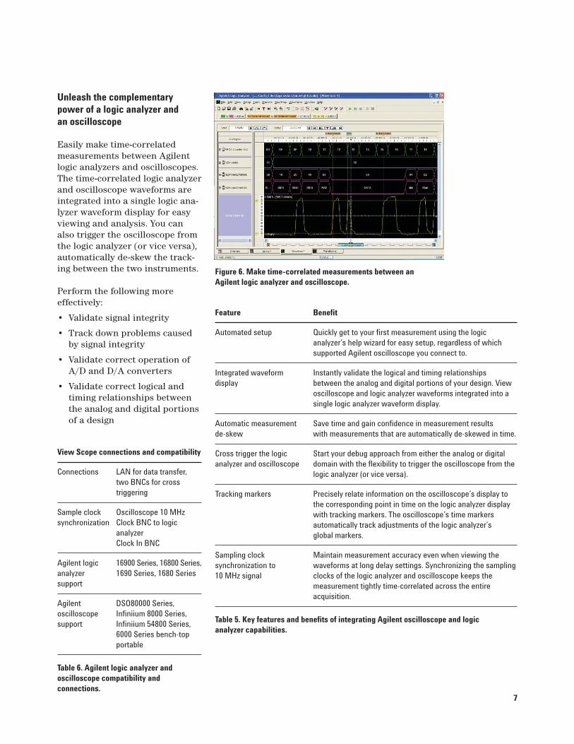
Unleash the complementary power of a logic analyzer and an oscilloscope
Easily make time-correlatedmeasurements between Agilentlogic analyzers and oscilloscopes.The time-correlated logic analyzerand oscilloscope waveforms areintegrated into a single logic ana-lyzer waveform display for easyviewing and analysis. You canalso trigger the oscilloscope fromthe logic analyzer (or vice versa),automatically de-skew the track-ing between the two instruments.
Perform the following more effectively:
• Validate signal integrity
• Track down problems causedby signal integrity
• Validate correct operation ofA/D and D/A converters
• Validate correct logical andtiming relationships betweenthe analog and digital portionsof a design
Figure 6. Make time-correlated measurements between anAgilent logic analyzer and oscilloscope.
Feature Benefit
Automated setup Quickly get to your first measurement using the logic analyzer’s help wizard for easy setup, regardless of which supported Agilent oscilloscope you connect to.
Integrated waveform Instantly validate the logical and timing relationships display between the analog and digital portions of your design. View
oscilloscope and logic analyzer waveforms integrated into a single logic analyzer waveform display.
Automatic measurement Save time and gain confidence in measurement results de-skew with measurements that are automatically de-skewed in time.
Cross trigger the logic Start your debug approach from either the analog or digital analyzer and oscilloscope domain with the flexibility to trigger the oscilloscope from the
logic analyzer (or vice versa).
Tracking markers Precisely relate information on the oscilloscope’s display to the corresponding point in time on the logic analyzer display with tracking markers. The oscilloscope’s time markers automatically track adjustments of the logic analyzer’s global markers.
Sampling clock Maintain measurement accuracy even when viewing the synchronization to waveforms at long delay settings. Synchronizing the sampling 10 MHz signal clocks of the logic analyzer and oscilloscope keeps the
measurement tightly time-correlated across the entire acquisition.
Table 5. Key features and benefits of integrating Agilent oscilloscope and logic analyzer capabilities.
View Scope connections and compatibility
Connections LAN for data transfer, two BNCs for cross triggering
Sample clock Oscilloscope 10 MHz synchronization Clock BNC to logic
analyzer Clock In BNC
Agilent logic 16900 Series, 16800 Series, analyzer 1690 Series, 1680 Seriessupport
Agilent DSO80000 Series, oscilloscope Infiniium 8000 Series, support Infiniium 54800 Series,
6000 Series bench-top portable
Table 6. Agilent logic analyzer and oscilloscope compatibility and connections.
7
8
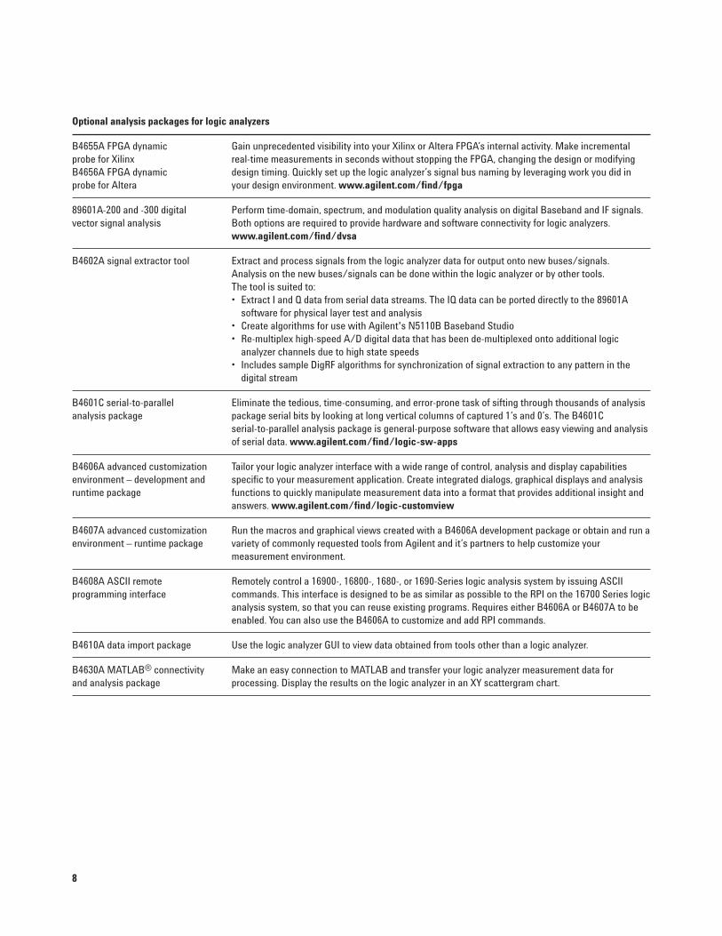
Optional analysis packages for logic analyzers
B4655A FPGA dynamic Gain unprecedented visibility into your Xilinx or Altera FPGA’s internal activity. Make incremental probe for Xilinx real-time measurements in seconds without stopping the FPGA, changing the design or modifying B4656A FPGA dynamic design timing. Quickly set up the logic analyzer’s signal bus naming by leveraging work you did in probe for Altera your design environment. www.agilent.com/find/fpga
89601A-200 and -300 digital Perform time-domain, spectrum, and modulation quality analysis on digital Baseband and IF signals. vector signal analysis Both options are required to provide hardware and software connectivity for logic analyzers.
www.agilent.com/find/dvsa
B4602A signal extractor tool Extract and process signals from the logic analyzer data for output onto new buses/signals. Analysis on the new buses/signals can be done within the logic analyzer or by other tools. The tool is suited to:• Extract I and Q data from serial data streams. The IQ data can be ported directly to the 89601A
software for physical layer test and analysis • Create algorithms for use with Agilent's N5110B Baseband Studio • Re-multiplex high-speed A/D digital data that has been de-multiplexed onto additional logic
analyzer channels due to high state speeds• Includes sample DigRF algorithms for synchronization of signal extraction to any pattern in the
digital stream
B4601C serial-to-parallel Eliminate the tedious, time-consuming, and error-prone task of sifting through thousands of analysis analysis package package serial bits by looking at long vertical columns of captured 1’s and 0’s. The B4601C
serial-to-parallel analysis package is general-purpose software that allows easy viewing and analysis of serial data. www.agilent.com/find/logic-sw-apps
B4606A advanced customization Tailor your logic analyzer interface with a wide range of control, analysis and display capabilities environment – development and specific to your measurement application. Create integrated dialogs, graphical displays and analysis runtime package functions to quickly manipulate measurement data into a format that provides additional insight and
answers. www.agilent.com/find/logic-customview
B4607A advanced customization Run the macros and graphical views created with a B4606A development package or obtain and run a environment – runtime package variety of commonly requested tools from Agilent and it’s partners to help customize your
measurement environment.
B4608A ASCII remote Remotely control a 16900-, 16800-, 1680-, or 1690-Series logic analysis system by issuing ASCII programming interface commands. This interface is designed to be as similar as possible to the RPI on the 16700 Series logic
analysis system, so that you can reuse existing programs. Requires either B4606A or B4607A to be enabled. You can also use the B4606A to customize and add RPI commands.
B4610A data import package Use the logic analyzer GUI to view data obtained from tools other than a logic analyzer.
B4630A MATLAB® connectivity Make an easy connection to MATLAB and transfer your logic analyzer measurement data for and analysis package processing. Display the results on the logic analyzer in an XY scattergram chart.
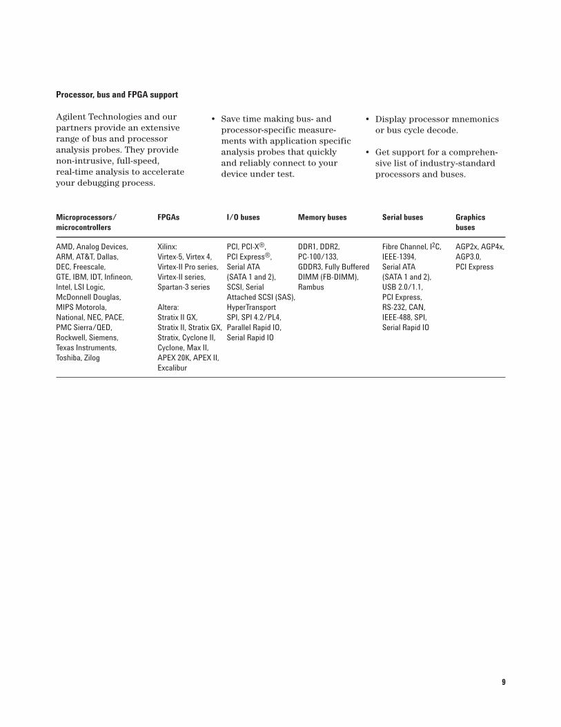
Microprocessors/ FPGAs I/O buses Memory buses Serial buses Graphics microcontrollers buses
AMD, Analog Devices, Xilinx: PCI, PCI-X®, DDR1, DDR2, Fibre Channel, I2C, AGP2x, AGP4x, ARM, AT&T, Dallas, Virtex-5, Virtex 4, PCI Express®, PC-100/133, IEEE-1394, AGP3.0,DEC, Freescale, Virtex-II Pro series, Serial ATA GDDR3, Fully Buffered Serial ATA PCI ExpressGTE, IBM, IDT, Infineon, Virtex-II series, (SATA 1 and 2), DIMM (FB-DIMM), (SATA 1 and 2),Intel, LSI Logic, Spartan-3 series SCSI, Serial Rambus USB 2.0/1.1, McDonnell Douglas, Attached SCSI (SAS), PCI Express, MIPS Motorola, Altera: HyperTransport RS-232, CAN, National, NEC, PACE, Stratix II GX, SPI, SPI 4.2/PL4, IEEE-488, SPI,PMC Sierra/QED, Stratix II, Stratix GX, Parallel Rapid IO, Serial Rapid IORockwell, Siemens, Stratix, Cyclone II, Serial Rapid IOTexas Instruments, Cyclone, Max II, Toshiba, Zilog APEX 20K, APEX II,
Excalibur
Processor, bus and FPGA support
Agilent Technologies and ourpartners provide an extensiverange of bus and processor analysis probes. They providenon-intrusive, full-speed, real-time analysis to accelerateyour debugging process.
• Save time making bus- andprocessor-specific measure-ments with application specificanalysis probes that quicklyand reliably connect to yourdevice under test.
• Display processor mnemonicsor bus cycle decode.
• Get support for a comprehen-sive list of industry-standardprocessors and buses.
9
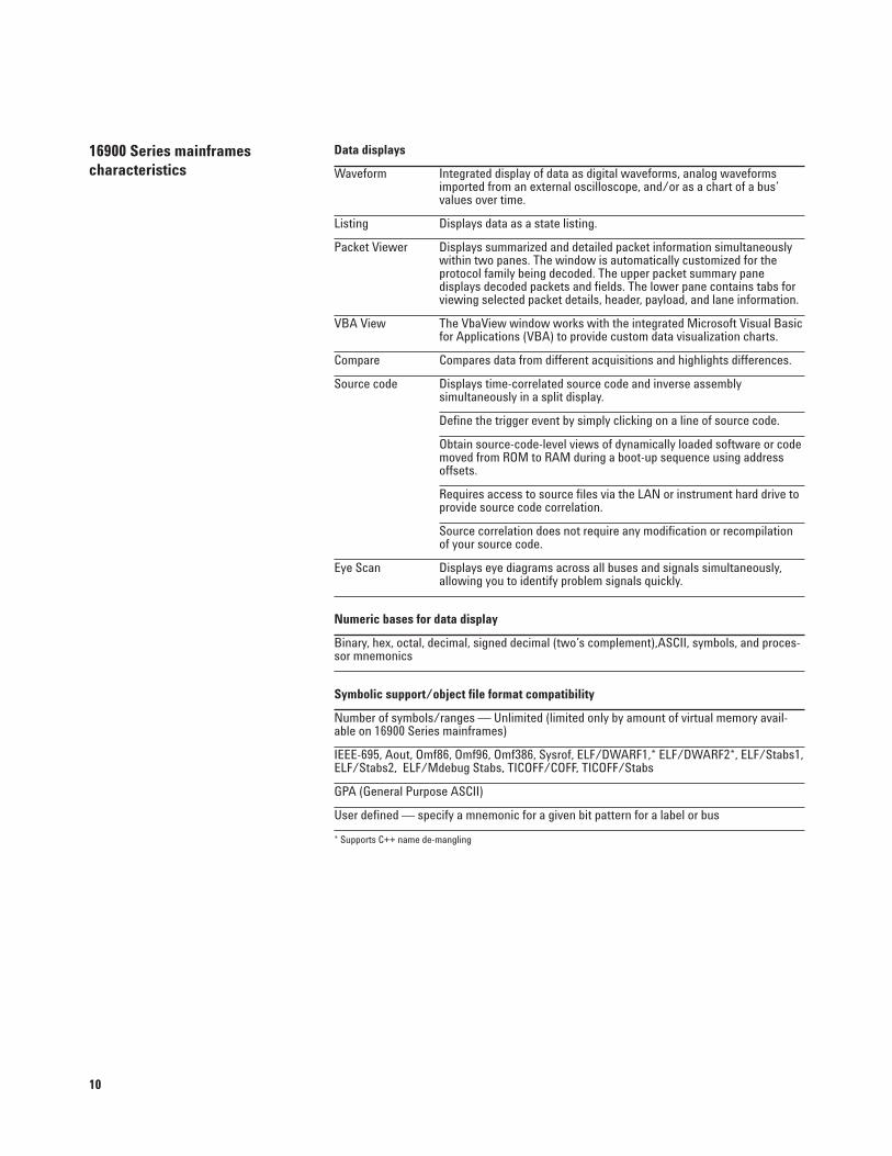
Data displays
Waveform Integrated display of data as digital waveforms, analog waveforms imported from an external oscilloscope, and/or as a chart of a bus’values over time.
Listing Displays data as a state listing.
Packet Viewer Displays summarized and detailed packet information simultaneously within two panes. The window is automatically customized for the protocol family being decoded. The upper packet summary pane displays decoded packets and fields. The lower pane contains tabs for viewing selected packet details, header, payload, and lane information.
VBA View The VbaView window works with the integrated Microsoft Visual Basic for Applications (VBA) to provide custom data visualization charts.
Compare Compares data from different acquisitions and highlights differences.
Source code Displays time-correlated source code and inverse assembly simultaneously in a split display.
Define the trigger event by simply clicking on a line of source code.
Obtain source-code-level views of dynamically loaded software or codemoved from ROM to RAM during a boot-up sequence using address offsets.
Requires access to source files via the LAN or instrument hard drive toprovide source code correlation.
Source correlation does not require any modification or recompilationof your source code.
Eye Scan Displays eye diagrams across all buses and signals simultaneously, allowing you to identify problem signals quickly.
Numeric bases for data display
Binary, hex, octal, decimal, signed decimal (two’s complement),ASCII, symbols, and proces-sor mnemonics
Symbolic support/object file format compatibility
Number of symbols/ranges — Unlimited (limited only by amount of virtual memory avail-able on 16900 Series mainframes)
IEEE-695, Aout, Omf86, Omf96, Omf386, Sysrof, ELF/DWARF1,* ELF/DWARF2*, ELF/Stabs1,ELF/Stabs2, ELF/Mdebug Stabs, TICOFF/COFF, TICOFF/Stabs
GPA (General Purpose ASCII)
User defined — specify a mnemonic for a given bit pattern for a label or bus
* Supports C++ name de-mangling
16900 Series mainframes characteristics
10
11
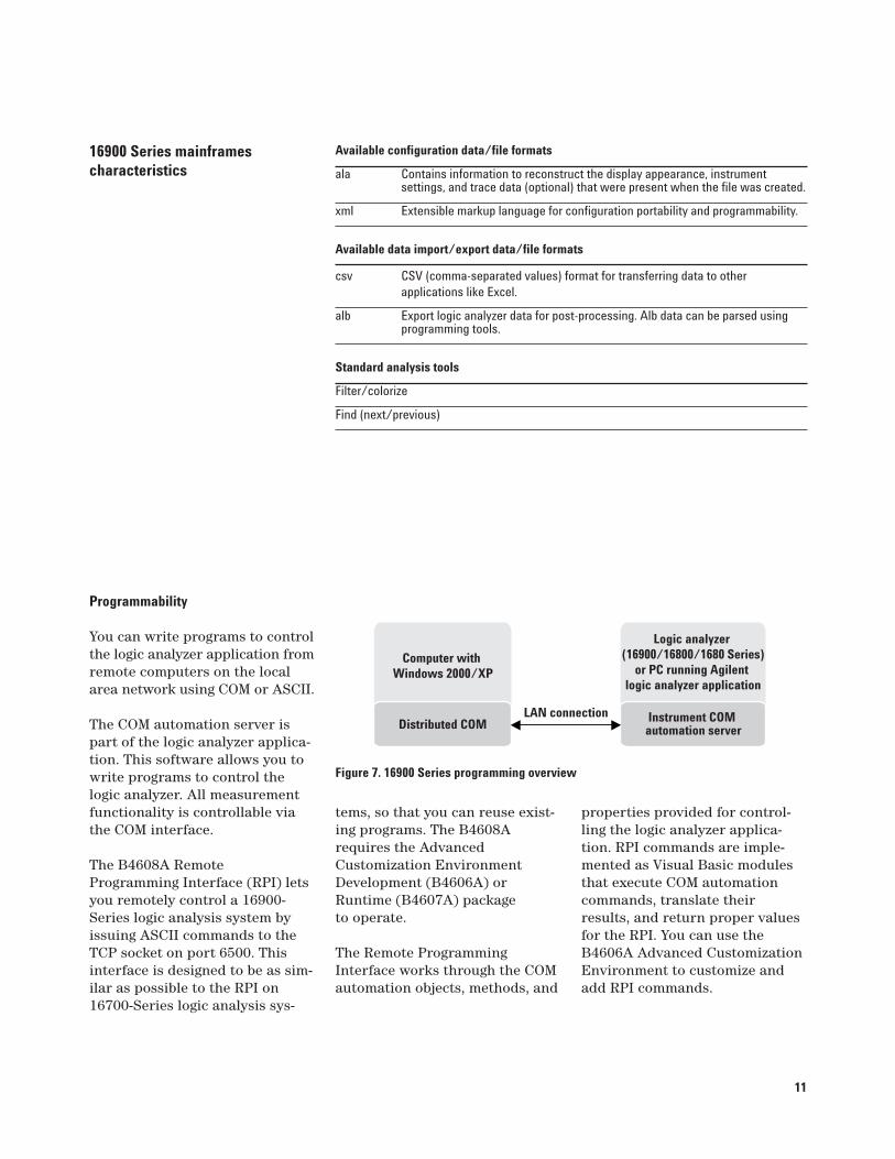
Available configuration data/file formats
ala Contains information to reconstruct the display appearance, instrumentsettings, and trace data (optional) that were present when the file was created.
xml Extensible markup language for configuration portability and programmability.
Available data import/export data/file formats
csv CSV (comma-separated values) format for transferring data to other applications like Excel.
alb Export logic analyzer data for post-processing. Alb data can be parsed using programming tools.
Standard analysis tools
Filter/colorize
Find (next/previous)
16900 Series mainframes characteristics
Programmability
You can write programs to controlthe logic analyzer application fromremote computers on the localarea network using COM or ASCII.
The COM automation server ispart of the logic analyzer applica-tion. This software allows you towrite programs to control thelogic analyzer. All measurementfunctionality is controllable viathe COM interface.
The B4608A RemoteProgramming Interface (RPI) letsyou remotely control a 16900-Series logic analysis system byissuing ASCII commands to theTCP socket on port 6500. Thisinterface is designed to be as sim-ilar as possible to the RPI on16700-Series logic analysis sys-
Computer with Windows 2000/XP
Logic analyzer (16900/16800/1680 Series)
or PC running Agilent logic analyzer application
LAN connectionDistributed COM Instrument COM
automation server
Figure 7. 16900 Series programming overview
tems, so that you can reuse exist-ing programs. The B4608Arequires the AdvancedCustomization EnvironmentDevelopment (B4606A) orRuntime (B4607A) package to operate.
The Remote ProgrammingInterface works through the COMautomation objects, methods, and
properties provided for control-ling the logic analyzer applica-tion. RPI commands are imple-mented as Visual Basic modulesthat execute COM automationcommands, translate theirresults, and return proper valuesfor the RPI. You can use theB4606A Advanced CustomizationEnvironment to customize andadd RPI commands.
12
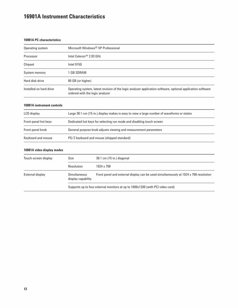
16901A Instrument Characteristics
16901A PC characteristics
Operating system Microsoft Windows® XP Professional
Processor Intel Celeron™ 2.93 GHz
Chipset Intel 915G
System memory 1 GB SDRAM
Hard disk drive 80 GB (or higher)
Installed on hard drive Operating system, latest revision of the logic analyzer application software, optional application software ordered with the logic analyzer
16901A instrument controls
LCD display Large 38.1-cm (15-in.) display makes is easy to view a large number of waveforms or states
Front-panel hot keys Dedicated hot keys for selecting run mode and disabling touch screen
Front-panel knob General-purpose knob adjusts viewing and measurement parameters
Keyboard and mouse PS/2 keyboard and mouse (shipped standard)
16901A video display modes
Touch-screen display Size 38.1 cm (15 in.) diagonal
Resolution 1024 x 768
External display Simultaneous Front panel and external display can be used simultaneously at 1024 x 768 resolutiondisplay capability
Supports up to four external monitors at up to 1600x1200 (with PCI video card)
13
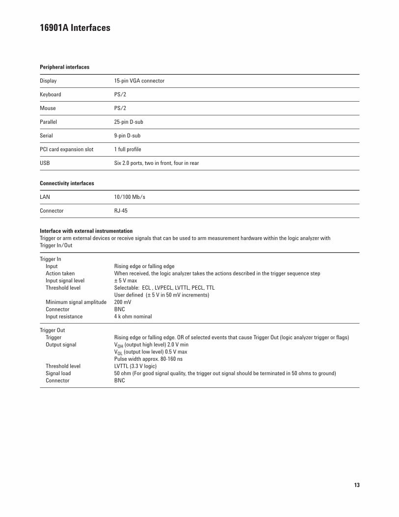
16901A Interfaces
Peripheral interfaces
Display 15-pin VGA connector
Keyboard PS/2
Mouse PS/2
Parallel 25-pin D-sub
Serial 9-pin D-sub
PCI card expansion slot 1 full profile
USB Six 2.0 ports, two in front, four in rear
Connectivity interfaces
LAN 10/100 Mb/s
Connector RJ-45
Interface with external instrumentationTrigger or arm external devices or receive signals that can be used to arm measurement hardware within the logic analyzer with Trigger In/Out
Trigger InInput Rising edge or falling edge Action taken When received, the logic analyzer takes the actions described in the trigger sequence stepInput signal level ± 5 V max Threshold level Selectable: ECL , LVPECL, LVTTL, PECL, TTL
User defined (± 5 V in 50 mV increments)Minimum signal amplitude 200 mV Connector BNC Input resistance 4 k ohm nominal
Trigger Out Trigger Rising edge or falling edge. OR of selected events that cause Trigger Out (logic analyzer trigger or flags) Output signal VOH (output high level) 2.0 V min
VOL (output low level) 0.5 V maxPulse width approx. 80-160 ns
Threshold level LVTTL (3.3 V logic) Signal load 50 ohm (For good signal quality, the trigger out signal should be terminated in 50 ohms to ground) Connector BNC
14
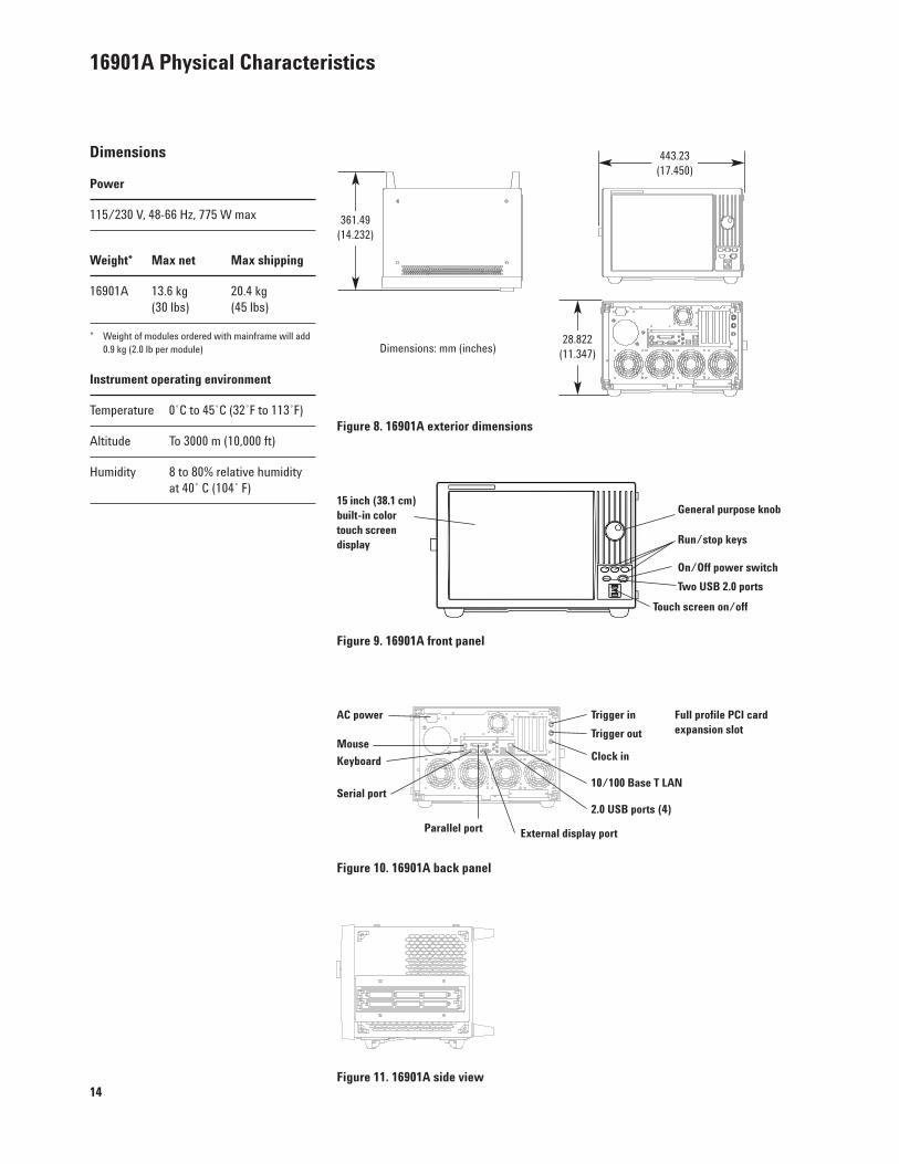
Figure 10. 16901A back panel
Full profile PCI cardexpansion slot
External display portParallel port
Serial port10/100 Base T LAN
2.0 USB ports (4)
Clock in
Trigger out
Trigger in
Keyboard
Mouse
AC power
Figure 9. 16901A front panel
On/Off power switch
15 inch (38.1 cm)built-in colortouch screendisplay
General purpose knob
Run/stop keys
Touch screen on/off
16901A Physical Characteristics
Dimensions
Power
115/230 V, 48-66 Hz, 775 W max
Weight* Max net Max shipping
16901A 13.6 kg 20.4 kg (30 lbs) (45 lbs)
* Weight of modules ordered with mainframe will add0.9 kg (2.0 lb per module)
Instrument operating environment
Temperature 0˚C to 45˚C (32˚F to 113˚F)
Altitude To 3000 m (10,000 ft)
Humidity 8 to 80% relative humidity at 40˚ C (104˚ F)
Figure 8. 16901A exterior dimensions
Figure 11. 16901A side view
361.49(14.232)
Dimensions: mm (inches)28.822
(11.347)
443.23(17.450)
Two USB 2.0 ports
15
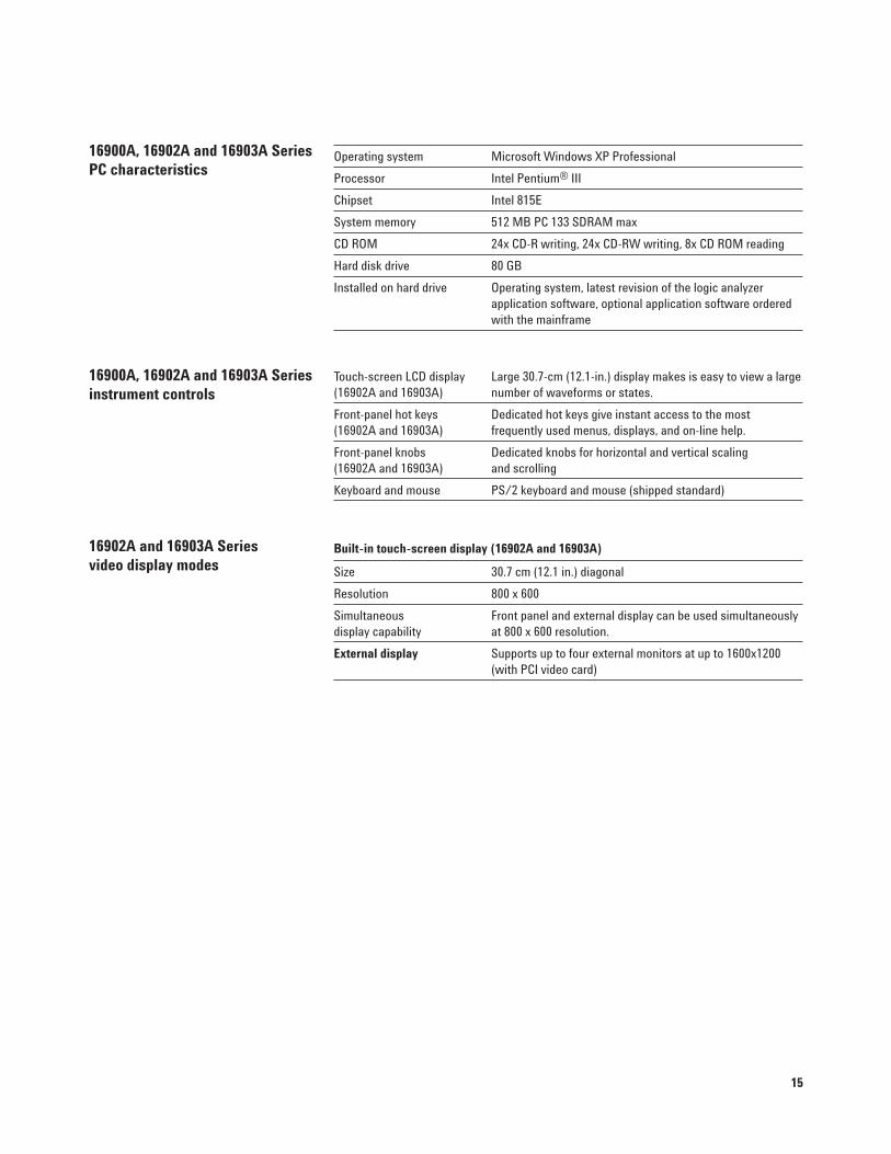
Operating system Microsoft Windows XP Professional
Processor Intel Pentium® III
Chipset Intel 815E
System memory 512 MB PC 133 SDRAM max
CD ROM 24x CD-R writing, 24x CD-RW writing, 8x CD ROM reading
Hard disk drive 80 GB
Installed on hard drive Operating system, latest revision of the logic analyzer application software, optional application software orderedwith the mainframe
Touch-screen LCD display Large 30.7-cm (12.1-in.) display makes is easy to view a large(16902A and 16903A) number of waveforms or states.
Front-panel hot keys Dedicated hot keys give instant access to the most (16902A and 16903A) frequently used menus, displays, and on-line help.
Front-panel knobs Dedicated knobs for horizontal and vertical scaling (16902A and 16903A) and scrolling
Keyboard and mouse PS/2 keyboard and mouse (shipped standard)
Built-in touch-screen display (16902A and 16903A)
Size 30.7 cm (12.1 in.) diagonal
Resolution 800 x 600
Simultaneous Front panel and external display can be used simultaneously display capability at 800 x 600 resolution.
External display Supports up to four external monitors at up to 1600x1200(with PCI video card)
16900A, 16902A and 16903A SeriesPC characteristics
16900A, 16902A and 16903A Seriesinstrument controls
16902A and 16903A Seriesvideo display modes
16
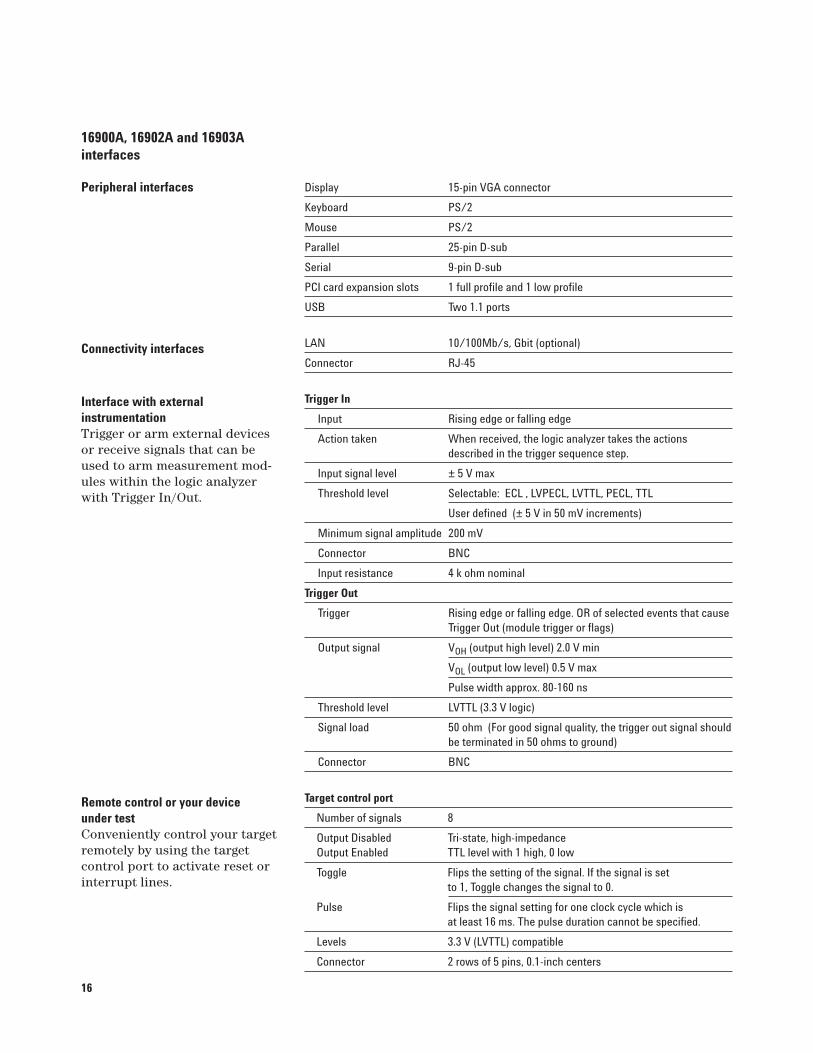
Display 15-pin VGA connector
Keyboard PS/2
Mouse PS/2
Parallel 25-pin D-sub
Serial 9-pin D-sub
PCI card expansion slots 1 full profile and 1 low profile
USB Two 1.1 ports
LAN 10/100Mb/s, Gbit (optional)
Connector RJ-45
Trigger In
Input Rising edge or falling edge
Action taken When received, the logic analyzer takes the actionsdescribed in the trigger sequence step.
Input signal level ± 5 V max
Threshold level Selectable: ECL , LVPECL, LVTTL, PECL, TTL
User defined (± 5 V in 50 mV increments)
Minimum signal amplitude 200 mV
Connector BNC
Input resistance 4 k ohm nominal
Trigger Out
Trigger Rising edge or falling edge. OR of selected events that causeTrigger Out (module trigger or flags)
Output signal VOH (output high level) 2.0 V min
VOL (output low level) 0.5 V max
Pulse width approx. 80-160 ns
Threshold level LVTTL (3.3 V logic)
Signal load 50 ohm (For good signal quality, the trigger out signal shouldbe terminated in 50 ohms to ground)
Connector BNC
Target control port
Number of signals 8
Output Disabled Tri-state, high-impedanceOutput Enabled TTL level with 1 high, 0 low
Toggle Flips the setting of the signal. If the signal is set to 1, Toggle changes the signal to 0.
Pulse Flips the signal setting for one clock cycle which is at least 16 ms. The pulse duration cannot be specified.
Levels 3.3 V (LVTTL) compatible
Connector 2 rows of 5 pins, 0.1-inch centers
Interface with external instrumentation Trigger or arm external devicesor receive signals that can beused to arm measurement mod-ules within the logic analyzerwith Trigger In/Out.
Remote control or your device under testConveniently control your targetremotely by using the target control port to activate reset orinterrupt lines.
16900A, 16902A and 16903Ainterfaces
Peripheral interfaces
Connectivity interfaces
17
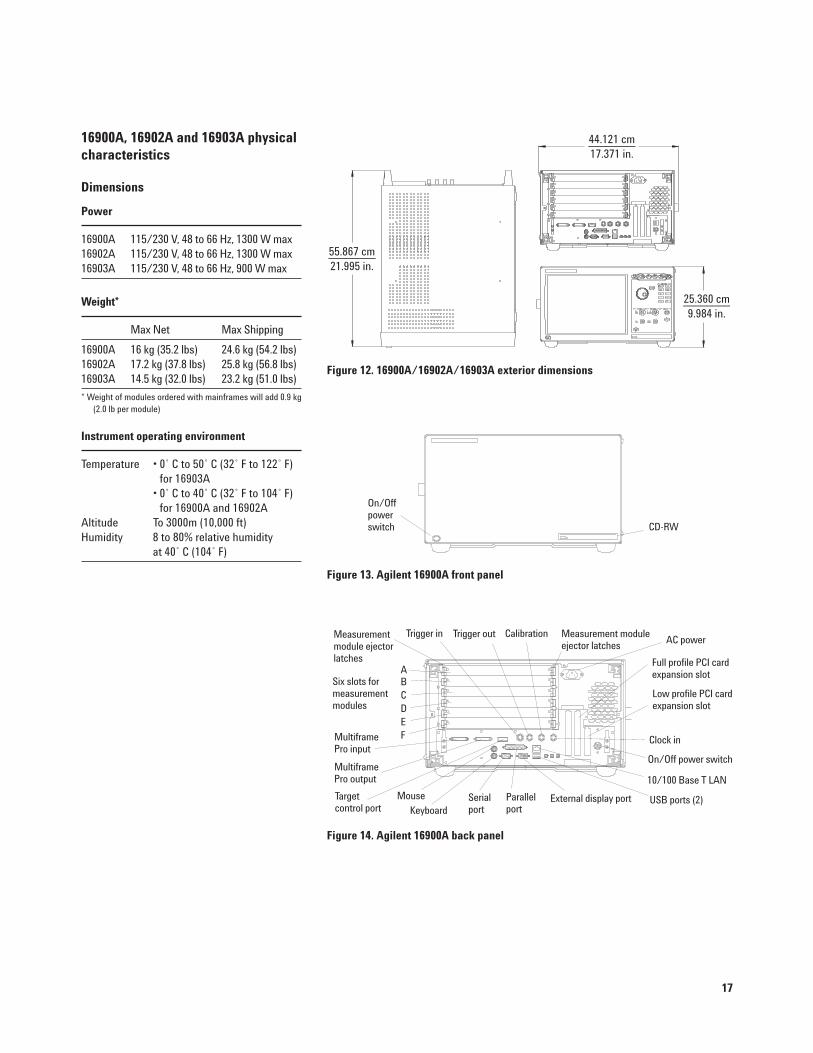
16900A, 16902A and 16903A physical characteristics
Dimensions
55.867 cm________21.995 in.
44.121 cm________17.371 in.
25.360 cm________9.984 in.
Figure 12. 16900A/16902A/16903A exterior dimensions
CD-RW
On/Offpowerswitch
Power
16900A 115/230 V, 48 to 66 Hz, 1300 W max 16902A 115/230 V, 48 to 66 Hz, 1300 W max 16903A 115/230 V, 48 to 66 Hz, 900 W max
Weight*
Max Net Max Shipping
16900A 16 kg (35.2 lbs) 24.6 kg (54.2 lbs)16902A 17.2 kg (37.8 lbs) 25.8 kg (56.8 lbs)16903A 14.5 kg (32.0 lbs) 23.2 kg (51.0 lbs)
* Weight of modules ordered with mainframes will add 0.9 kg(2.0 lb per module)
Instrument operating environment
Temperature • 0˚ C to 50˚ C (32˚ F to 122˚ F) for 16903A
• 0˚ C to 40˚ C (32˚ F to 104˚ F) for 16900A and 16902A
Altitude To 3000m (10,000 ft)Humidity 8 to 80% relative humidity
at 40˚ C (104˚ F)
Figure 13. Agilent 16900A front panel
Figure 14. Agilent 16900A back panel
Low profile PCI cardexpansion slot
On/Off power switch
Full profile PCI cardexpansion slot
External display portParallelport
Serialport
Target control port
10/100 Base T LAN
USB ports (2)
Measurement moduleejector latches
Clock in
CalibrationTrigger outTrigger in
Keyboard
Mouse
ABCDEF
Measurementmodule ejectorlatches
Multiframe Pro output
Multiframe Pro input
AC power
Six slots formeasurementmodules
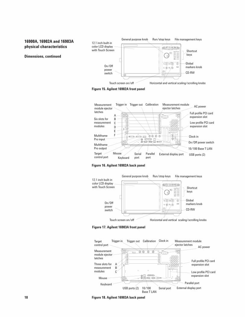
18 Figure 18. Agilent 16903A back panel
16900A, 16902A and 16903Aphysical characteristics
Dimensions, continued
Low profile PCI cardexpansion slot
Full profile PCI cardexpansion slot
External display port
Parallel port
Serial port10/100Base T LAN
USB ports (2)
Measurement moduleejector latches
Clock inCalibrationTrigger outTrigger inTarget control port
Keyboard
Mouse
Measurementmodule ejectorlatches
AC power
Figure 16. Agilent 16902A back panel
Low profile PCI cardexpansion slot
On/Off power switch
Full profile PCI cardexpansion slot
External display portParallelport
Serialport
Target control port
10/100 Base T LAN
USB ports (2)
Measurement moduleejector latches
Clock in
CalibrationTrigger outTrigger in
Keyboard
Mouse
ABCDEF
Measurementmodule ejectorlatches
Multiframe Pro output
Multiframe Pro input
AC power
Six slots formeasurementmodules
ABC
Three slots formeasurementmodules
Figure 17. Agilent 16903A front panel
On/Offpowerswitch
12.1 inch built-incolor LCD displaywith Touch Screen
General purpose knob Run/stop keys File management keys
Shortcutkeys
Global markers knob
CD-RW
Horizontal and vertical scaling/scrolling knobsTouch screen on/off
Figure 15. Agilent 16902A front panel
On/Offpowerswitch
12.1 inch built-in color LCD display with Touch Screen
General purpose knob Run/stop keys File management keys
Shortcutkeys
Global markers knob
CD-RW
Horizontal and vertical scaling/scrolling knobsTouch screen on/off
19
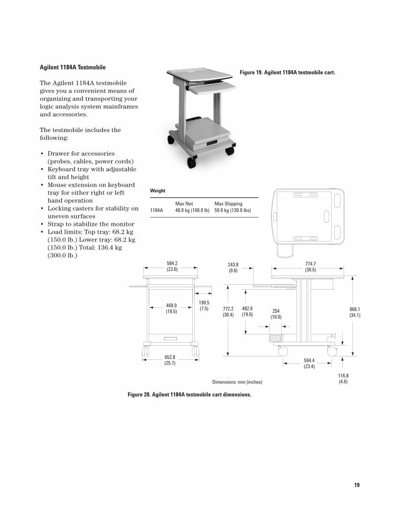
Agilent 1184A Testmobile
The Agilent 1184A testmobilegives you a convenient means oforganizing and transporting yourlogic analysis system mainframesand accessories.
The testmobile includes the following:
• Drawer for accessories(probes, cables, power cords)
• Keyboard tray with adjustabletilt and height
• Mouse extension on keyboard tray for either right or lefthand operation
• Locking casters for stability onuneven surfaces
• Strap to stabilize the monitor• Load limits: Top tray: 68.2 kg
(150.0 lb.) Lower tray: 68.2 kg(150.0 lb.) Total: 136.4 kg (300.0 lb.)
Figure 19. Agilent 1184A testmobile cart.
Figure 20. Agilent 1184A testmobile cart dimensions.
Weight
Max Net Max Shipping1184A 48.0 kg (106.0 lb) 59.0 kg (130.0 lbs)
Dimensions: mm (inches)
772.2(30.4)
482.6(19.0)
254(10.0)
243.8(9.6)
774.7(30.5)
866.1(34.1)
116.8(4.6)
594.4(23.4)
190.5(7.5)
469.9(18.5)
652.8(25.7)
584.2(23.0)
20
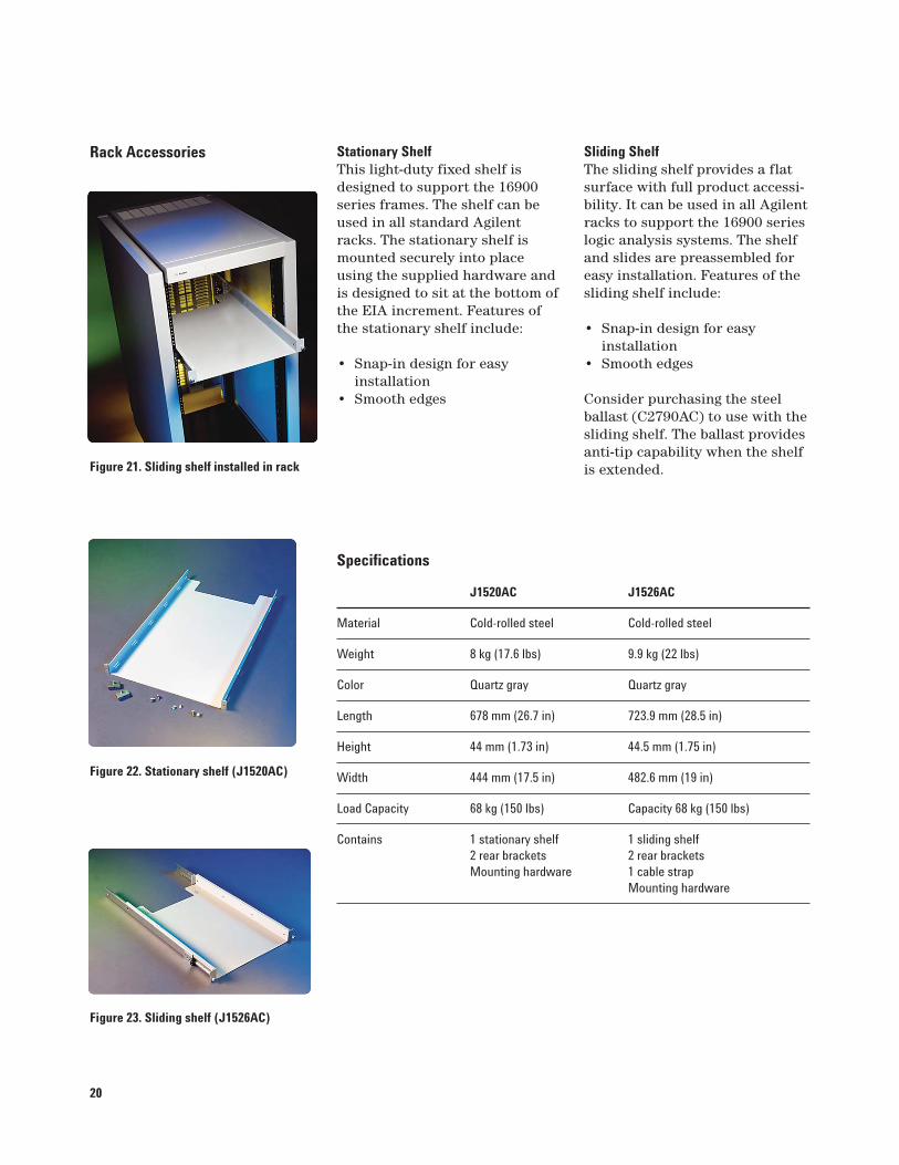
Stationary ShelfThis light-duty fixed shelf isdesigned to support the 16900series frames. The shelf can beused in all standard Agilentracks. The stationary shelf ismounted securely into placeusing the supplied hardware andis designed to sit at the bottom ofthe EIA increment. Features ofthe stationary shelf include:
• Snap-in design for easy installation
• Smooth edges
Specifications
J1520AC J1526AC
Material Cold-rolled steel Cold-rolled steel
Weight 8 kg (17.6 lbs) 9.9 kg (22 lbs)
Color Quartz gray Quartz gray
Length 678 mm (26.7 in) 723.9 mm (28.5 in)
Height 44 mm (1.73 in) 44.5 mm (1.75 in)
Width 444 mm (17.5 in) 482.6 mm (19 in)
Load Capacity 68 kg (150 lbs) Capacity 68 kg (150 lbs)
Contains 1 stationary shelf 1 sliding shelf2 rear brackets 2 rear bracketsMounting hardware 1 cable strap
Mounting hardware
Rack Accessories Sliding ShelfThe sliding shelf provides a flatsurface with full product accessi-bility. It can be used in all Agilentracks to support the 16900 serieslogic analysis systems. The shelfand slides are preassembled foreasy installation. Features of thesliding shelf include:
• Snap-in design for easy installation
• Smooth edges
Consider purchasing the steel ballast (C2790AC) to use with thesliding shelf. The ballast providesanti-tip capability when the shelfis extended.
Figure 23. Sliding shelf (J1526AC)
Figure 22. Stationary shelf (J1520AC)
Figure 21. Sliding shelf installed in rack
21
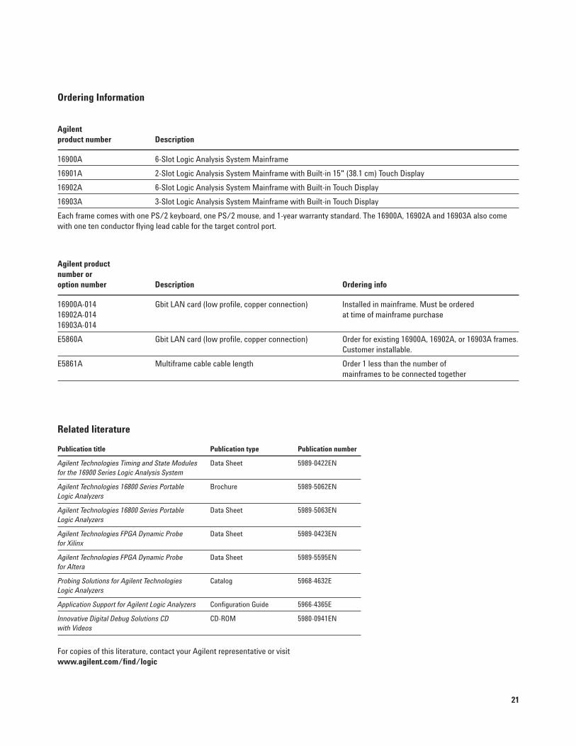
Ordering Information
Agilent product number Description
16900A 6-Slot Logic Analysis System Mainframe
16901A 2-Slot Logic Analysis System Mainframe with Built-in 15" (38.1 cm) Touch Display
16902A 6-Slot Logic Analysis System Mainframe with Built-in Touch Display
16903A 3-Slot Logic Analysis System Mainframe with Built-in Touch Display
Each frame comes with one PS/2 keyboard, one PS/2 mouse, and 1-year warranty standard. The 16900A, 16902A and 16903A also comewith one ten conductor flying lead cable for the target control port.
Agilent product number or option number Description Ordering info
16900A-014 Gbit LAN card (low profile, copper connection) Installed in mainframe. Must be ordered 16902A-014 at time of mainframe purchase 16903A-014
E5860A Gbit LAN card (low profile, copper connection) Order for existing 16900A, 16902A, or 16903A frames.Customer installable.
E5861A Multiframe cable cable length Order 1 less than the number of mainframes to be connected together
Related literature
Publication title Publication type Publication number
Agilent Technologies Timing and State Modules Data Sheet 5989-0422ENfor the 16900 Series Logic Analysis System
Agilent Technologies 16800 Series Portable Brochure 5989-5062ENLogic Analyzers
Agilent Technologies 16800 Series Portable Data Sheet 5989-5063ENLogic Analyzers
Agilent Technologies FPGA Dynamic Probe Data Sheet 5989-0423ENfor Xilinx
Agilent Technologies FPGA Dynamic Probe Data Sheet 5989-5595ENfor Altera
Probing Solutions for Agilent Technologies Catalog 5968-4632ELogic Analyzers
Application Support for Agilent Logic Analyzers Configuration Guide 5966-4365E
Innovative Digital Debug Solutions CD CD-ROM 5980-0941EN with Videos
For copies of this literature, contact your Agilent representative or visit www.agilent.com/find/logic
www.agilent.com/find/open
Agilent Open simplifies the process of
connecting and programming test systems
to help engineers design, validate and
manufacture electronic products. Agilent
offers open connectivity for a broad range
of system-ready instruments, open industry
software, PC-standard I/O and global
support, which are combined to more easily
integrate test system development.
Microsoft and Windows are U.S. registeredtrademarks of Microsoft Corporation.
Pentium is a U.S. registered trademark ofIntel Corporation.
MATLAB® is a U.S. registered trademark ofThe MathWorks, Inc.
PCI-X and PCI Express are registered trademarks of PCI-SIG.
www.agilent.com
For more information on Agilent
Technologies’ products, applications
or services, please contact your local
Agilent office. The complete list is
available at:
www.agilent.com/find/contactus
Phone or Fax
United States:(tel) 800 829 4444(fax) 800 829 4433
Canada:(tel) 877 894 4414(fax) 800 746 4866
China:(tel) 800 810 0189(fax) 800 820 2816
Europe:(tel) 31 20 547 2111
Japan:(tel) (81) 426 56 7832(fax) (81) 426 56 7840
Korea:(tel) (080) 769 0800(fax) (080) 769 0900
Latin America:(tel) (305) 269 7500
Taiwan:(tel) 0800 047 866 (fax) 0800 286 331
Other Asia Pacific Countries:(tel) (65) 6375 8100 (fax) (65) 6755 0042Email: [email protected]: 09/14/06
Product specifications and descriptions
in this document subject to change
without notice.
© Agilent Technologies, Inc. 2007
Printed in USA, November 1, 2007
5989-7584EN
www.agilent.com/find/emailupdates
Get the latest information on the products
and applications you select.
www.agilent.com/find/quick
Quickly choose and use your test
equipment solutions with confidence.
Agilent Email Updates
Agilent Direct
AgilentOpen
Remove all doubt
Our repair and calibration services will get
your equipment back to you, performing
like new, when promised. You will get full
value out of your Agilent equipment
throughout its lifetime. Your equipment
will be serviced by Agilent-trained
technicians using the latest factory
calibration procedures, automated repair
diagnostics and genuine parts. You will
always have the utmost confidence in
your measurements.
Agilent offers a wide range of additional
expert test and measurement services for
your equipment, including initial start-up
assistance onsite education and training,
as well as design, system integration,
and project management.
For more information on repair and
calibration services, go to
www.agilent.com/find/removealldoubt