agilent 1260 infinity micro-scale fraction collector/spotter user manual · 2020-04-29 · this...
TRANSCRIPT
Agilent 1260 InfinityMicro-scale Fraction Collector/Spotter
User Manual
Agilent 1260 Infinity Micro-scale Fraction Collector/Spotter
Notices© Agilent Technologies, Inc. 2010, 2013
No part of this manual may be reproduced in any form or by any means (including elec-tronic storage and retrieval or translation into a foreign language) without prior agree-ment and written consent from Agilent Technologies, Inc. as governed by United States and international copyright laws.
Microsoft ® is a U.S. registered trademark of Microsoft Corporation.
Manual Part NumberG1364-90013 Rev. B
Edition10/2013
Printed in Germany
Agilent TechnologiesHewlett-Packard-Strasse 8 76337 Waldbronn
Warranty
The material contained in this docu-ment is provided “as is,” and is sub-ject to being changed, without notice, in future editions. Further, to the max-imum extent permitted by applicable law, Agilent disclaims all warranties, either express or implied, with regard to this manual and any information contained herein, including but not limited to the implied warranties of merchantability and fitness for a par-ticular purpose. Agilent shall not be liable for errors or for incidental or consequential damages in connec-tion with the furnishing, use, or per-formance of this document or of any information contained herein. Should Agilent and the user have a separate written agreement with warranty terms covering the material in this document that conflict with these terms, the warranty terms in the sep-arate agreement shall control.
Technology Licenses The hardware and/or software described in this document are furnished under a license and may be used or copied only in accor-dance with the terms of such license.
Restricted Rights LegendIf software is for use in the performance of a U.S. Government prime contract or subcon-tract, Software is delivered and licensed as “Commercial computer software” as defined in DFAR 252.227-7014 (June 1995), or as a “commercial item” as defined in FAR 2.101(a) or as “Restricted computer soft-ware” as defined in FAR 52.227-19 (June 1987) or any equivalent agency regulation or contract clause. Use, duplication or disclo-sure of Software is subject to Agilent Tech-nologies’ standard commercial license terms, and non-DOD Departments and Agencies of the U.S. Government will
receive no greater than Restricted Rights as defined in FAR 52.227-19(c)(1-2) (June 1987). U.S. Government users will receive no greater than Limited Rights as defined in FAR 52.227-14 (June 1987) or DFAR 252.227-7015 (b)(2) (November 1995), as applicable in any technical data.
Safety Notices
CAUTION
A CAUTION notice denotes a haz-ard. It calls attention to an operat-ing procedure, practice, or the like that, if not correctly performed or adhered to, could result in damage to the product or loss of important data. Do not proceed beyond a CAUTION notice until the indicated conditions are fully understood and met.
WARNING
A WARNING notice denotes a hazard. It calls attention to an operating procedure, practice, or the like that, if not correctly per-formed or adhered to, could result in personal injury or death. Do not proceed beyond a WARNING notice until the indicated condi-tions are fully understood and met.
In This Guide…This manual contains user information about the Agilent 1260 Infinity Micro- scale Fraction Collector/Spotter G1364D. It is intended for users that will operate the Agilent 1260 Infinity Micro- scale Fraction Collector/Spotter either for micro- scale fraction collection or for MALDI Spotting. For information about installation, advanced troubleshooting, repair and a complete list of internal parts please refer to the Agilent 1260 Infinity Fraction Collectors Service Manual G1364- 90111.
1 Installing the Micro-scale Fraction Collector/Spotter
This chapter provides information about the installation of the Agilent 1260 Infinity Micro- scale Fraction Collector/Spotter.
2 Configuration and Operation of the Micro-scale Fraction Collector/Spotter
This chapter describes the configuration, method setup and operation of the micro collector/spotter.
3 Troubleshooting and Test Functions
This chapter describes the modules built- in troubleshooting, test and maintenance functions.
4 Maintenance and Simple Repairs
This chapter contains instructions on maintenance and simple repair procedures.
5 Parts and Materials
This chapter contains selected illustrations and lists for identification of parts and materials that are required for maintenance, or exchanged in simple repair procedures.
6 Specifications
This chapter contains performance specifications of the micro collector/spotter.
A Safety Information
This appendix provides a safety summary.
Agilent 1260 Infinity Micro-scale Fraction Collector/Spotter User Manual 3

4 Agilent 1260 Infinity Micro-scale Fraction Collector/Spotter User Manual
Contents
Contents
1 Installing the Micro-scale Fraction Collector/Spotter 9
Site Requirements 10
Power Consideration 10Power Cords 11Bench Space 12Environment 12
Unpacking the Fraction Collector 15
Damaged Packaging 15Delivery Checklist 15Accessory Kits 16
Optimizing the Stack Configuration 18
Installing the Micro-scale Fraction Collector/Spotter 20
Installing a Thermostatted Fraction Collector 24
Micro-scale Fraction Collector/Spotter Trays 28
Installing the Fraction Collector Trays 28Numbering of Vial, Well-plate and Spot Positions 29
Configure Well-plate Types 30
Transporting the Micro-scale Collector Spotter 34
2 Configuration and Operation of the Micro-scale Fraction Collector/Spotter 35
Introduction 36
Initialization and Reset 39
Configuration of the Micro-scale Fraction Collector/Spotter 40
Choosing and Installing the Micro-scale Fraction Collector/Spotter Capillary 40
Configuration of the ChemStation 44
Setting up a Micro-scale Fraction Collector/Spotter Method 49
Agilent 1260 Infinity Micro-scale Fraction Collector/Spotter User Manual 5
Contents
Fraction Preview 53Starting Your Run with Fraction Collection or MALDI Spotting 55Assignment of Start Location 56Online Tick Marks 59
Viewing your Results 60
Data Analysis 60Report 61
Online Matrix Delivery 62
Check-out Procedures 66
Check-out Procedure for Micro-scale Fraction Collection 66Check-out Procedure for MALDI Spotting 68
3 Troubleshooting and Test Functions 71
Status Indicators 72
Power Supply Indicator 72Instrument Status Indicator 73
Deactivating the Door Lock Sensor 74
Maintenance Functions 75
Transport Unit Self Alignment 77
Arm Length Calibration 79
Position Accuracy Calibration for 384-Well Plates 82
Position Accuracy Calibration for MALDI Targets 84
Single Step Commands 87
4 Maintenance and Simple Repairs 89
Introduction into Repairing the Micro-scale Fraction Collector/Spotter 90
Simple Repairs 90Cleaning the Micro Collector/Spotter 91Cleaning the Waste Port 92
6 Agilent 1260 Infinity Micro-scale Fraction Collector/Spotter User Manual
Contents
Replacing the Micro-scale Fraction Collector/Spotter Lamp Assembly 95
Simple Repairs Procedures 99
Replacing Micro-scale Fraction Collector/Spotter Capillary Assembly 100Exchanging the Capillary Guiding Assembly 103Exchanging the Flap Septum and the Waste Tubing 105Exchanging the Internal Tray 107
5 Parts and Materials 109
Supported Trays for the Micro-scale Fraction Collector/Spotter 110
List of Recommended Plates 112
MALDI Spotting Accessories 113
Supported MALDI Targets 115
Transport Unit Assembly 117
Internal Tray Assembly 118
Micro-scale Fraction Collector/Spotter Accessory Kit 119
6 Specifications 121
Performance Specifications for the Micro Collector/Spotter 122
A Safety Information 125
Safety Information 126
General 126Operation 127Safety Symbols 128
Lithium Batteries Information 129
Radio Interference 130
Test and Measurement 130
Sound Emission 131
Manufacturer’s Declaration 131
Agilent 1260 Infinity Micro-scale Fraction Collector/Spotter User Manual 7
Contents
Solvent Information 132
Solvents 132
Agilent Technologies on Internet 133
8 Agilent 1260 Infinity Micro-scale Fraction Collector/Spotter User Manual
Agilent 1260 Infinity Series Micro-scale Fraction Collector/SpotterUser Manual
1Installing the Micro-scale Fraction Collector/Spotter
Site Requirements 10
Unpacking the Fraction Collector 15
Optimizing the Stack Configuration 18
Installing the Micro-scale Fraction Collector/Spotter 20
Installing a Thermostatted Fraction Collector 24
Micro-scale Fraction Collector/Spotter Trays 28
Configure Well-plate Types 30
Transporting the Micro-scale Collector Spotter 34
9Agilent Technologies
1 Installing the Micro-scale Fraction Collector/SpotterSite Requirements
Site Requirements
A suitable site environment is important to ensure optimum performance of the micro- scale fraction collector/spotter.
Power Consideration
The micro- scale fraction collector/spotter power supply has wide- ranging capability (see Table 1 on page 13). Consequently there is no voltage selector in the rear of the micro- scale fraction collector/spotter. There are also no externally accessible fuses, as automatic electronic fuses are integrated in the power supply.
The thermostatted micro- scale fraction collector/spotter comprises two modules, the micro- scale fraction collector/spotter (G1364D) and the thermostat (G1330B). Both modules have a separate power supply and a power plug for the line connections. The two modules are connected by a
10 Agilent 1260 Infinity Micro-scale Fraction Collector/Spotter User Manual
Installing the Micro-scale Fraction Collector/Spotter 1Site Requirements
control cable and both are turned on by the micro- scale fraction collector/spotter module. The thermostat power supply has two externally accessible fuses.
Power Cords
Your micro- scale fraction collector/spotter is delivered with a power cord which matches the wall socket of your particular country or region. The plug on the power cord which connects to the rear of the instrument is identical for all types of power cord.
WARNING To disconnect the micro-scale fraction collector/spotter from line power, unplug the power cord. The power supply still uses some power, even if the power switch on the front panel is turned off.
WARNING To disconnect the thermostatted micro-scale fraction collector/spotter from line power, unplug the power cord from the micro-scale fraction collector/spotter and the thermostat. The power supplies still use some power, even if the power switch on the front panel is turned off. Please make sure that it is always possible to access the power plug.
WARNING Shock hazard or damage of your instrumentation can result if the devices are connected to a line voltage higher than specified.
WARNING Never operate your instrumentation from a power outlet that has no ground connection. Never use a power cord other than the power cord designed for your region.
WARNING Never use cables other than the ones supplied by Agilent Technologies to ensure proper functionality and compliance with safety or EMC regulations.
Agilent 1260 Infinity Micro-scale Fraction Collector/Spotter User Manual 11
1 Installing the Micro-scale Fraction Collector/SpotterSite Requirements
Bench Space
The micro- scale fraction collector/spotter dimensions and weight (see Table 1 on page 13) allow the instrument to be placed on almost any laboratory bench. The instrument requires an additional 2.5 cm (1.0 inch) of space on either side, and approximately 8 cm (3.1 inches) at the rear for the circulation of air, and room for electrical connections. Ensure the micro- scale fraction collector/spotter is installed in a horizontal position.
The thermostatted micro- scale fraction collector/spotter dimensions and weight (see Table 2 on page 13) allow the instrument to be placed on almost any laboratory bench. The instrument requires an additional 25 cm (10 inches) of space on either side for the circulation of air, and approximately 8 cm (3.1 inches) at the rear for electrical connections. Ensure the micro- scale fraction collector/spotter is installed in a horizontal position.
If a complete Agilent 1260 Infinity LC System is to be installed on the bench, make sure that the bench is designed to carry the weight of all the modules. For a complete system including the thermostatted micro- scale fraction collector/spotter it is recommended to position the modules in two stacks, see “Recommend Stack Configuration for micro- scale collector/spotter in the capillary or nanoflow system” on page 19. Make sure that in this configuration there is 25 cm (10 inches) space on either side of the thermostatted micro- scale fraction collector/spotter for the circulation of air.
Environment
Your micro- scale fraction collector/spotter will work within specifications at ambient temperatures and relative humidity as described in Table 1 and Table 2 on page 13.
CAUTION Do not store, ship or use your micro-scale fraction collector/spotter under conditions where temperature fluctuations may cause condensation within the micro-scale fraction collector/spotter. Condensation will damage the system electronics. If your micro-scale fraction collector/spotter was shipped in cold weather, leave it in its box, and allow it to warm up slowly to room temperature to avoid condensation.
12 Agilent 1260 Infinity Micro-scale Fraction Collector/Spotter User Manual
Installing the Micro-scale Fraction Collector/Spotter 1Site Requirements
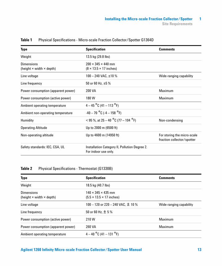
Table 1 Physical Specifications - Micro-scale Fraction Collector/Spotter G1364D
Type Specification Comments
Weight 13.5 kg (29.8 lbs)
Dimensions(height × width × depth)
200 × 345 × 440 mm(8 × 13.5 × 17 inches)
Line voltage 100 – 240 VAC, ±10 % Wide-ranging capability
Line frequency 50 or 60 Hz, ±5 %
Power consumption (apparent power) 200 VA Maximum
Power consumption (active power) 180 W Maximum
Ambient operating temperature 4 – 45 °C (41 – 113 °F)
Ambient non-operating temperature -40 – 70 °C (-4 – 158 °F)
Humidity < 95 %, at 25 – 40 °C (77 – 104 °F) Non-condensing
Operating Altitude Up to 2000 m (6500 ft)
Non-operating altitude Up to 4600 m (14950 ft) For storing the micro-scale fraction collector/spotter
Safety standards: IEC, CSA, UL Installation Category II, Pollution Degree 2.For indoor use only.
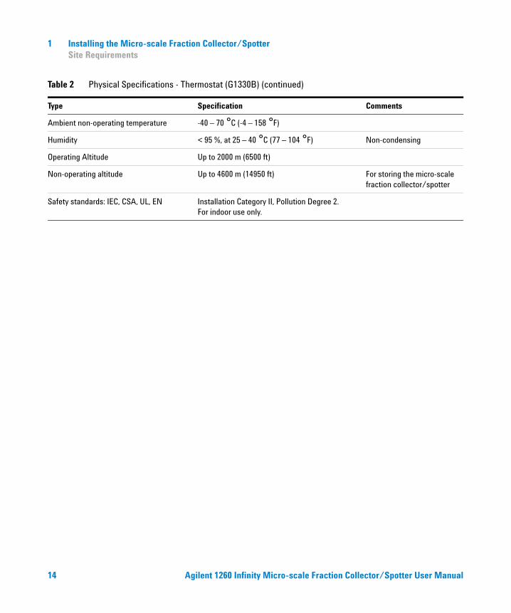
Table 2 Physical Specifications - Thermostat (G1330B)
Type Specification Comments
Weight 18.5 kg (40.7 lbs)
Dimensions(height × width × depth)
140 × 345 × 435 mm(5.5 × 13.5 × 17 inches)
Line voltage 100 – 120 or 220 – 240 VAC, ± 10 % Wide-ranging capability
Line frequency 50 or 60 Hz, ± 5 %
Power consumption (active power) 210 W Maximum
Power consumption (apparent power) 260 VA Maximum
Ambient operating temperature 4 – 40 °C (41 – 131 °F)
Agilent 1260 Infinity Micro-scale Fraction Collector/Spotter User Manual 13
1 Installing the Micro-scale Fraction Collector/SpotterSite Requirements
Ambient non-operating temperature -40 – 70 °C (-4 – 158 °F)
Humidity < 95 %, at 25 – 40 °C (77 – 104 °F) Non-condensing
Operating Altitude Up to 2000 m (6500 ft)
Non-operating altitude Up to 4600 m (14950 ft) For storing the micro-scale fraction collector/spotter
Safety standards: IEC, CSA, UL, EN Installation Category II, Pollution Degree 2.For indoor use only.
Table 2 Physical Specifications - Thermostat (G1330B) (continued)
Type Specification Comments
14 Agilent 1260 Infinity Micro-scale Fraction Collector/Spotter User Manual
Installing the Micro-scale Fraction Collector/Spotter 1Unpacking the Fraction Collector
Unpacking the Fraction Collector
Damaged Packaging
Upon receipt of your micro- scale fraction collector/spotter, inspect the shipping containers for any signs of damage. If the containers or cushioning material are damaged, keep them until the contents have been checked for completeness and the micro- scale fraction collector/spotter has been mechanically and electrically checked. If the shipping container or cushioning material is damaged, notify the carrier and keep the shipping material for the carrier‘s inspection.
Delivery Checklist
Ensure all parts and materials have been delivered with the micro- scale fraction collector/spotter. For this compare the shipment content with the checklist included in each instrument box. Please report missing or damaged parts to your local Agilent Technologies sales and service office.
The Agilent 1260 Infinity Micro- scale Fraction Collector/Spotter is available as:
• G1364D micro- scale fraction collector/spotter, designed for flow rates below 100 μl/min and for use with well plates and Eppendorf tubes.
• G1364D Thermostatted option of the micro- scale fraction collector/spotter. This option can be setup by additionally ordering and installing a G1330B fraction collector thermostat
CAUTION If you need to ship the micro-scale fraction collector/spotter at a later date, always use the shipping protection foam parts (see “Transporting the Micro-scale Collector Spotter” on page 34).
CAUTION If there are signs of damage to the micro-scale fraction collector/spotter, please do not attempt to install the micro-scale fraction collector/spotter.
Agilent 1260 Infinity Micro-scale Fraction Collector/Spotter User Manual 15
1 Installing the Micro-scale Fraction Collector/SpotterUnpacking the Fraction Collector
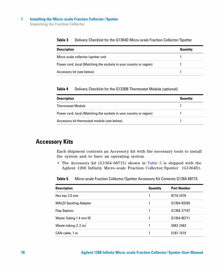
Accessory Kits
Each shipment contents an Accessory kit with the necessary tools to install the system and to have an operating system.
• The Accessory kit (G1364- 68715) shown in Table 5 is shipped with the Agilent 1260 Infinity Micro- scale Fraction Collector/Spotter (G1364D).
Table 3 Delivery Checklist for the G1364D Micro-scale Fraction Collector/Spotter
Description Quantity
Micro-scale collector/spotter unit 1
Power cord, local (Matching the sockets in your country or region) 1
Accessory kit (see below) 1
Table 4 Delivery Checklist for the G1330B Thermostat Module (optional)
Description Quantity
Thermostat Module 1
Power cord, local (Matching the sockets in your country or region) 1
Accessory kit thermostat module (see below) 1
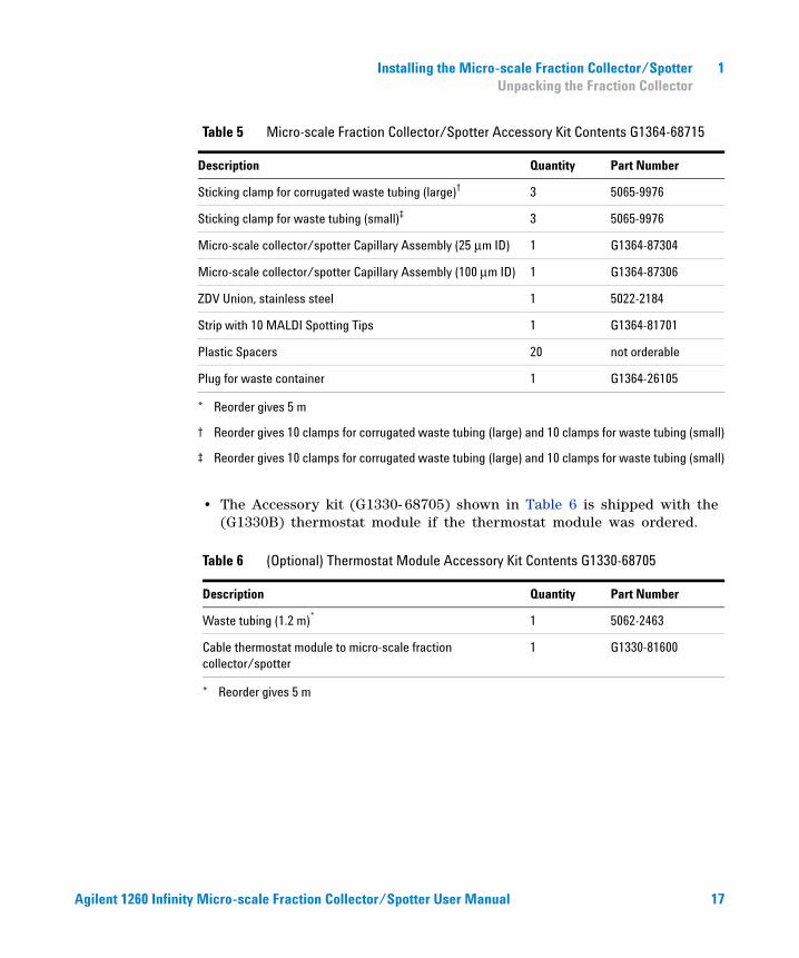
Table 5 Micro-scale Fraction Collector/Spotter Accessory Kit Contents G1364-68715
Description Quantity Part Number
Hex key 2.0 mm 1 8710-2476
MALDI Spotting Adapter 1 G1364-83205
Flap Septum 1 G1364-27107
Waste Tubing 1.4 mm ID 1 G1364-86711
Waste tubing (1.2 m)* 1 5062-2463
CAN cable, 1 m 1 5181-1519
16 Agilent 1260 Infinity Micro-scale Fraction Collector/Spotter User Manual
Installing the Micro-scale Fraction Collector/Spotter 1Unpacking the Fraction Collector
• The Accessory kit (G1330- 68705) shown in Table 6 is shipped with the (G1330B) thermostat module if the thermostat module was ordered.
Sticking clamp for corrugated waste tubing (large)† 3 5065-9976
Sticking clamp for waste tubing (small)‡ 3 5065-9976
Micro-scale collector/spotter Capillary Assembly (25 μm ID) 1 G1364-87304
Micro-scale collector/spotter Capillary Assembly (100 μm ID) 1 G1364-87306
ZDV Union, stainless steel 1 5022-2184
Strip with 10 MALDI Spotting Tips 1 G1364-81701
Plastic Spacers 20 not orderable
Plug for waste container 1 G1364-26105
* Reorder gives 5 m
† Reorder gives 10 clamps for corrugated waste tubing (large) and 10 clamps for waste tubing (small)
‡ Reorder gives 10 clamps for corrugated waste tubing (large) and 10 clamps for waste tubing (small)
Table 6 (Optional) Thermostat Module Accessory Kit Contents G1330-68705
Description Quantity Part Number
Waste tubing (1.2 m)*
* Reorder gives 5 m
1 5062-2463
Cable thermostat module to micro-scale fraction collector/spotter
1 G1330-81600
Table 5 Micro-scale Fraction Collector/Spotter Accessory Kit Contents G1364-68715
Description Quantity Part Number
Agilent 1260 Infinity Micro-scale Fraction Collector/Spotter User Manual 17
1 Installing the Micro-scale Fraction Collector/SpotterOptimizing the Stack Configuration
Optimizing the Stack Configuration
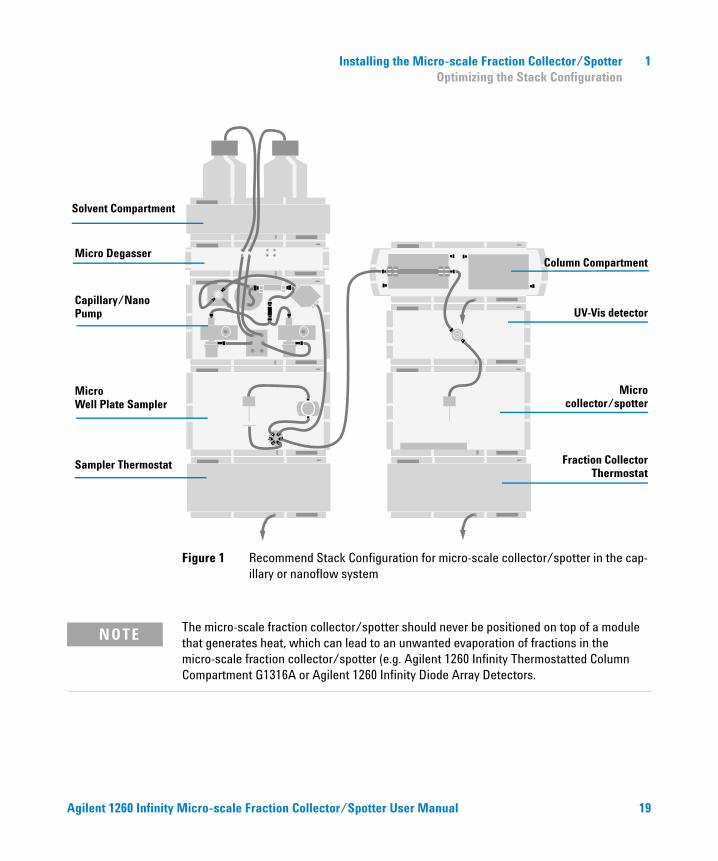
If your Agilent 1260 Infinity Micro- scale Fraction Collector/Spotter is part of a system, you can ensure optimum performance and minimum delay volume by installing the following configuration.
• Figure 1 on page 19 shows the configuration recommended for the micro- scale fraction collector/spotter within an Agilent 1260 Infinity Capillary or Nanoflow LC system
18 Agilent 1260 Infinity Micro-scale Fraction Collector/Spotter User Manual
Installing the Micro-scale Fraction Collector/Spotter 1Optimizing the Stack Configuration
Figure 1 Recommend Stack Configuration for micro-scale collector/spotter in the cap-illary or nanoflow system
MicroWell Plate Sampler
Capillary/NanoPump
Micro Degasser
Sampler Thermostat
Column Compartment
UV-Vis detector
Microcollector/spotter
Fraction CollectorThermostat
Solvent Compartment
NOTE The micro-scale fraction collector/spotter should never be positioned on top of a module that generates heat, which can lead to an unwanted evaporation of fractions in the micro-scale fraction collector/spotter (e.g. Agilent 1260 Infinity Thermostatted Column Compartment G1316A or Agilent 1260 Infinity Diode Array Detectors.
Agilent 1260 Infinity Micro-scale Fraction Collector/Spotter User Manual 19
1 Installing the Micro-scale Fraction Collector/SpotterInstalling the Micro-scale Fraction Collector/Spotter
Installing the Micro-scale Fraction Collector/Spotter
1 Install the LAN interface board in the micro- scale fraction collector/spotter (if required).
2 Remove the adhesive tape which covers the side and front doors.
3 Open the front door and remove the left side door.
4 Remove the transport protection foam.
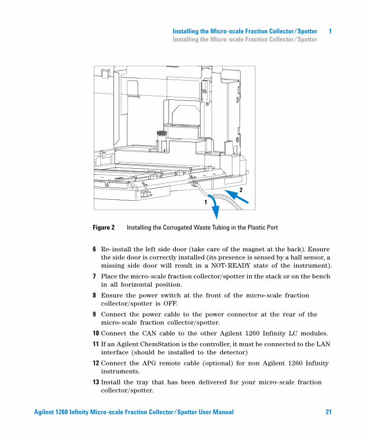
5 Install the corrugated waste tube in the plastic port at the front bottom center of the instrument. Slide the waste tubing coming from the internal tray (if present) through the plastic port and the corrugated waste tube (see Figure 2 on page 21). Route the corrugated waste tubing into a waste container.
Preparation Locate bench spaceProvide power connectionsUnpack the micro-scale fraction collector/spotter
Parts required Fraction CollectorPower cordChemstation or Agilent Instant Pilot G4208A
WARNING When opening capillary or tube fittings solvents may leak out. Please observe appropriate safety procedures (for example, goggles, safety gloves and protective clothing) as described in the material handling and safety data sheet supplied by the solvent vendor, especially when toxic or hazardous solvents are used.
WARNING To avoid personal injury, keep fingers away from the needle area during micro-scale fraction collector/spotter operation. Do not attempt to insert or remove a vial or a plate when the needle is positioned.
20 Agilent 1260 Infinity Micro-scale Fraction Collector/Spotter User Manual
Installing the Micro-scale Fraction Collector/Spotter 1Installing the Micro-scale Fraction Collector/Spotter
6 Re- install the left side door (take care of the magnet at the back). Ensure the side door is correctly installed (its presence is sensed by a hall sensor, a missing side door will result in a NOT- READY state of the instrument).
7 Place the micro- scale fraction collector/spotter in the stack or on the bench in all horizontal position.
8 Ensure the power switch at the front of the micro- scale fraction collector/spotter is OFF.
9 Connect the power cable to the power connector at the rear of the micro- scale fraction collector/spotter.
10 Connect the CAN cable to the other Agilent 1260 Infinity LC modules.
11 If an Agilent ChemStation is the controller, it must be connected to the LAN interface (should be installed to the detector)
12 Connect the APG remote cable (optional) for non Agilent 1260 Infinity instruments.
13 Install the tray that has been delivered for your micro- scale fraction collector/spotter.
Figure 2 Installing the Corrugated Waste Tubing in the Plastic Port
2
1
Agilent 1260 Infinity Micro-scale Fraction Collector/Spotter User Manual 21
1 Installing the Micro-scale Fraction Collector/SpotterInstalling the Micro-scale Fraction Collector/Spotter
14 Turn ON power by pushing the button at the lower left hand side of the micro- scale fraction collector/spotter.
15 The exhaust fan will turn ON and remove potential solvent vapor from the inside of the instrument. After 2 minutes close the front door. Then the micro- scale fraction collector/spotter will start the hardware initialization process. At the end of this process the status LED should be green.
NOTE The micro-scale fraction collector/spotter (G1364D) is shipped with 4 x well plate full tray. All other trays have to be ordered separately.
22 Agilent 1260 Infinity Micro-scale Fraction Collector/Spotter User Manual
Installing the Micro-scale Fraction Collector/Spotter 1Installing the Micro-scale Fraction Collector/Spotter
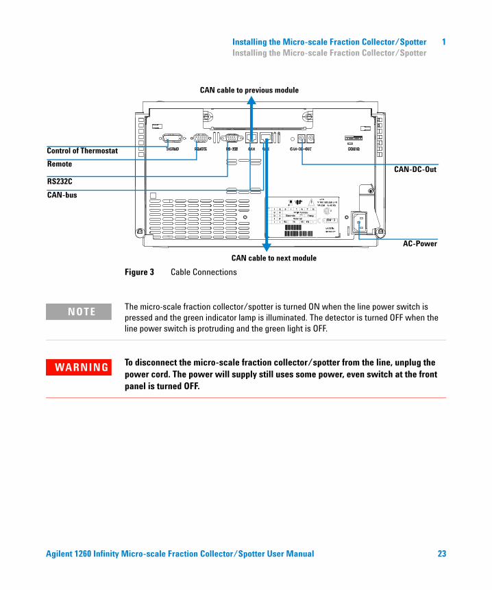
Figure 3 Cable Connections
RS232C
CAN-bus
Remote
CAN cable to next module
CAN cable to previous module
Control of Thermostat
CAN-DC-Out
AC-Power
NOTE The micro-scale fraction collector/spotter is turned ON when the line power switch is pressed and the green indicator lamp is illuminated. The detector is turned OFF when the line power switch is protruding and the green light is OFF.
WARNING To disconnect the micro-scale fraction collector/spotter from the line, unplug the power cord. The power will supply still uses some power, even switch at the front panel is turned OFF.
Agilent 1260 Infinity Micro-scale Fraction Collector/Spotter User Manual 23
1 Installing the Micro-scale Fraction Collector/SpotterInstalling a Thermostatted Fraction Collector
Installing a Thermostatted Fraction Collector
1 Place the thermostat on the bench.
2 Remove the front cover and route the condensation drain tube to a waste container.
3 Install the LAN interface board in the micro- scale fraction collector/spotter (if required).
4 Remove the adhesive tape which covers the side and front doors.
5 Open the front door and remove the left side door.
6 Remove the transport protection foam.
7 Install the corrugated waste tube in the plastic port at the front bottom center of the micro- scale fraction collector/spotter and route down into a waste container. Slide the waste tubing coming from the internal tray (if present) through the plastic port and the corrugated waste tube (see
Preparation Locate bench spaceProvide power connectionsUnpack the micro-scale fraction collector/spotter and the thermostat
Parts required Fraction Collector and thermostatPower cordsChemStation or Agilent Instant Pilot G4208A
WARNING Make sure the condensation drain tube runs down into a waste container without any (upwards) bends or curves. Free and unrestricted flow of the condensation into a waste container must be guaranteed. Make sure that the condensation drain tube is always above the liquid level in the container. If the tube is located in liquid the condensed water cannot flow out of the tube and the outlet is blocked. Any further condensation will then remain in the instrument. This may damage the instruments electronics.
CAUTION The micro-scale fraction collector/spotter thermostat requires 25 cm (10 inch) space on each for sufficient air circulation.
24 Agilent 1260 Infinity Micro-scale Fraction Collector/Spotter User Manual
Installing the Micro-scale Fraction Collector/Spotter 1Installing a Thermostatted Fraction Collector
Figure 2 on page 21). Route the corrugated waste tubing into a waste container.
8 Re- install the left side door (take care of the magnet at the back). Ensure the side door is correctly installed (its presence is sensed by a hall sensor, a missing side door will result in a NOT- READY state of the instrument).
9 Place the micro- scale fraction collector/spotter on top of the thermostat. Make sure that the micro- scale fraction collector/spotter is correctly engaged in the thermostat locks.
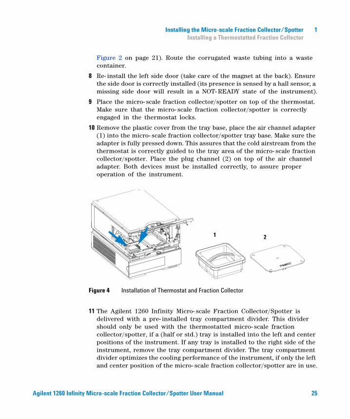
10 Remove the plastic cover from the tray base, place the air channel adapter (1) into the micro- scale fraction collector/spotter tray base. Make sure the adapter is fully pressed down. This assures that the cold airstream from the thermostat is correctly guided to the tray area of the micro- scale fraction collector/spotter. Place the plug channel (2) on top of the air channel adapter. Both devices must be installed correctly, to assure proper operation of the instrument.
11 The Agilent 1260 Infinity Micro- scale Fraction Collector/Spotter is delivered with a pre- installed tray compartment divider. This divider should only be used with the thermostatted micro- scale fraction collector/spotter, if a (half or std.) tray is installed into the left and center positions of the instrument. If any tray is installed to the right side of the instrument, remove the tray compartment divider. The tray compartment divider optimizes the cooling performance of the instrument, if only the left and center position of the micro- scale fraction collector/spotter are in use.
Figure 4 Installation of Thermostat and Fraction Collector
1 2
Agilent 1260 Infinity Micro-scale Fraction Collector/Spotter User Manual 25
1 Installing the Micro-scale Fraction Collector/SpotterInstalling a Thermostatted Fraction Collector
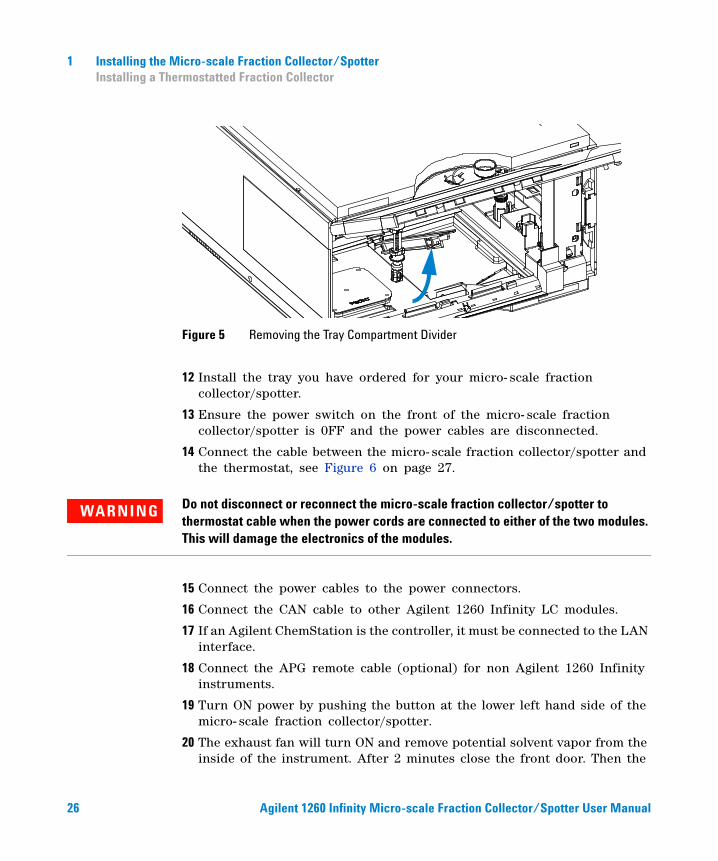
12 Install the tray you have ordered for your micro- scale fraction collector/spotter.
13 Ensure the power switch on the front of the micro- scale fraction collector/spotter is 0FF and the power cables are disconnected.
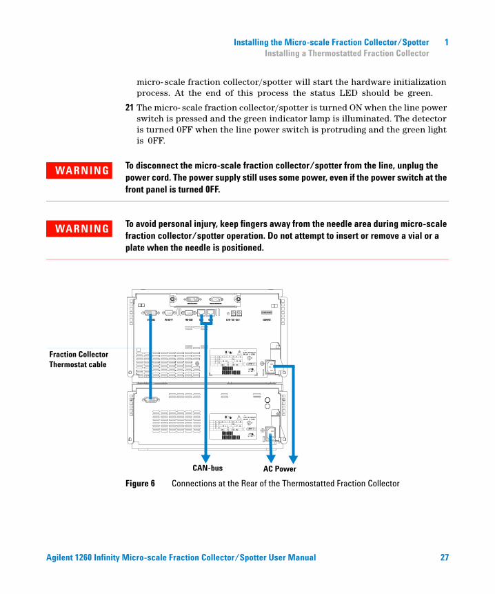
14 Connect the cable between the micro- scale fraction collector/spotter and the thermostat, see Figure 6 on page 27.
15 Connect the power cables to the power connectors.
16 Connect the CAN cable to other Agilent 1260 Infinity LC modules.
17 If an Agilent ChemStation is the controller, it must be connected to the LAN interface.
18 Connect the APG remote cable (optional) for non Agilent 1260 Infinity instruments.
19 Turn ON power by pushing the button at the lower left hand side of the micro- scale fraction collector/spotter.
20 The exhaust fan will turn ON and remove potential solvent vapor from the inside of the instrument. After 2 minutes close the front door. Then the
Figure 5 Removing the Tray Compartment Divider
WARNING Do not disconnect or reconnect the micro-scale fraction collector/spotter to thermostat cable when the power cords are connected to either of the two modules. This will damage the electronics of the modules.
26 Agilent 1260 Infinity Micro-scale Fraction Collector/Spotter User Manual
Installing the Micro-scale Fraction Collector/Spotter 1Installing a Thermostatted Fraction Collector
micro- scale fraction collector/spotter will start the hardware initialization process. At the end of this process the status LED should be green.
21 The micro- scale fraction collector/spotter is turned ON when the line power switch is pressed and the green indicator lamp is illuminated. The detector is turned 0FF when the line power switch is protruding and the green light is 0FF.
WARNING To disconnect the micro-scale fraction collector/spotter from the line, unplug the power cord. The power supply still uses some power, even if the power switch at the front panel is turned 0FF.
WARNING To avoid personal injury, keep fingers away from the needle area during micro-scale fraction collector/spotter operation. Do not attempt to insert or remove a vial or a plate when the needle is positioned.
Figure 6 Connections at the Rear of the Thermostatted Fraction Collector
Fraction Collector Thermostat cable
CAN-bus AC Power
Agilent 1260 Infinity Micro-scale Fraction Collector/Spotter User Manual 27
1 Installing the Micro-scale Fraction Collector/SpotterMicro-scale Fraction Collector/Spotter Trays
Micro-scale Fraction Collector/Spotter Trays
Installing the Fraction Collector Trays
1 Press the front door latch- holding button located at the front of the right- side cover.
2 Lift the front door.
3 Load the micro- scale fraction collector/spotter tray with 96 or 384 well plates, vial plates, Eppendorf plates or MALDI plate holders as required.
4 Slide the micro- scale fraction collector/spotter tray into the micro- scale fraction collector/spotter so that the rear of the tray is seated firmly against the rear of the tray area.
5 Press the front of the micro- scale fraction collector/spotter tray down to secure the tray in the micro- scale fraction collector/spotter.
6 Close the front door.
NOTE Installed trays are automatically detected and identified.
NOTE If the tray pops out of position the air channel adapter is not correctly inserted.
NOTE Before starting a run, the instrument has to be correctly configured in the user interface.
28 Agilent 1260 Infinity Micro-scale Fraction Collector/Spotter User Manual
Installing the Micro-scale Fraction Collector/Spotter 1Micro-scale Fraction Collector/Spotter Trays
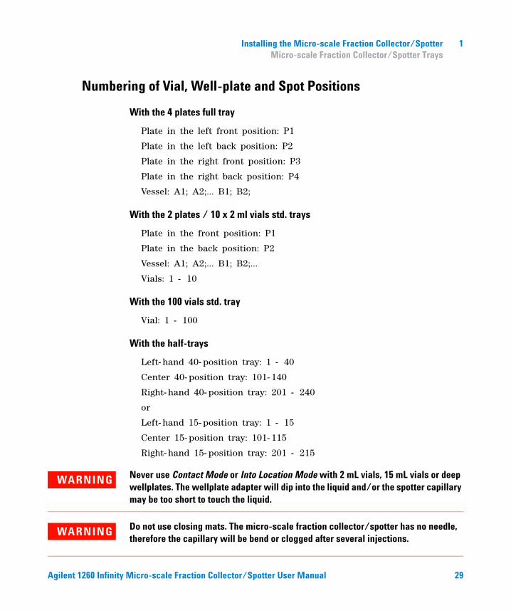
Numbering of Vial, Well-plate and Spot Positions
With the 4 plates full tray
Plate in the left front position: P1
Plate in the left back position: P2
Plate in the right front position: P3
Plate in the right back position: P4
Vessel: A1; A2;... B1; B2;
With the 2 plates / 10 x 2 ml vials std. trays
Plate in the front position: P1
Plate in the back position: P2
Vessel: A1; A2;... B1; B2;...
Vials: 1 - 10
With the 100 vials std. tray
Vial: 1 - 100
With the half-trays
Left- hand 40- position tray: 1 - 40
Center 40- position tray: 101- 140
Right- hand 40- position tray: 201 - 240
or
Left- hand 15- position tray: 1 - 15
Center 15- position tray: 101- 115
Right- hand 15- position tray: 201 - 215
WARNING Never use Contact Mode or Into Location Mode with 2 mL vials, 15 mL vials or deep wellplates. The wellplate adapter will dip into the liquid and/or the spotter capillary may be too short to touch the liquid.
WARNING Do not use closing mats. The micro-scale fraction collector/spotter has no needle, therefore the capillary will be bend or clogged after several injections.
Agilent 1260 Infinity Micro-scale Fraction Collector/Spotter User Manual 29
1 Installing the Micro-scale Fraction Collector/SpotterConfigure Well-plate Types
Configure Well-plate Types
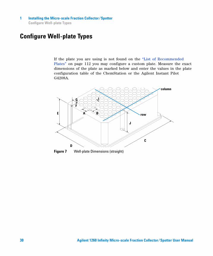
If the plate you are using is not found on the “List of Recommended Plates” on page 112 you may configure a custom plate. Measure the exact dimensions of the plate as marked below and enter the values in the plate configuration table of the ChemStation or the Agilent Instant Pilot G4208A.
Figure 7 Well-plate Dimensions (straight)
F
B
C
D
E A
G I
J
column
row
30 Agilent 1260 Infinity Micro-scale Fraction Collector/Spotter User Manual
Installing the Micro-scale Fraction Collector/Spotter 1Configure Well-plate Types
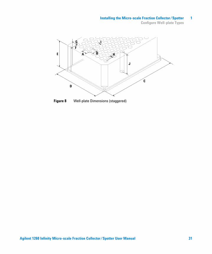
Figure 8 Well-plate Dimensions (staggered)
F
B
C
D
E A
G I
J
H
Agilent 1260 Infinity Micro-scale Fraction Collector/Spotter User Manual 31
1 Installing the Micro-scale Fraction Collector/SpotterConfigure Well-plate Types
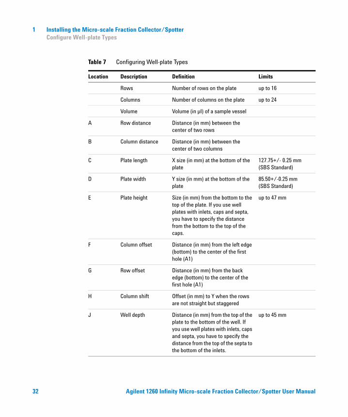
Table 7 Configuring Well-plate Types
Location Description Definition Limits
Rows Number of rows on the plate up to 16
Columns Number of columns on the plate up to 24
Volume Volume (in µI) of a sample vessel
A Row distance Distance (in mm) between the center of two rows
B Column distance Distance (in mm) between the center of two columns
C Plate length X size (in mm) at the bottom of the plate
127.75+/- 0.25 mm (SBS Standard)
D Plate width Y size (in mm) at the bottom of the plate
85.50+/-0.25 mm (SBS Standard)
E Plate height Size (in mm) from the bottom to the top of the plate. If you use well plates with inlets, caps and septa, you have to specify the distance from the bottom to the top of the caps.
up to 47 mm
F Column offset Distance (in mm) from the left edge (bottom) to the center of the first hole (A1)
G Row offset Distance (in mm) from the back edge (bottom) to the center of the first hole (A1)
H Column shift Offset (in mm) to Y when the rows are not straight but staggered
J WeIl depth Distance (in mm) from the top of the plate to the bottom of the well. If you use well plates with inlets, caps and septa, you have to specify the distance from the top of the septa to the bottom of the inlets.
up to 45 mm
32 Agilent 1260 Infinity Micro-scale Fraction Collector/Spotter User Manual
Installing the Micro-scale Fraction Collector/Spotter 1Configure Well-plate Types
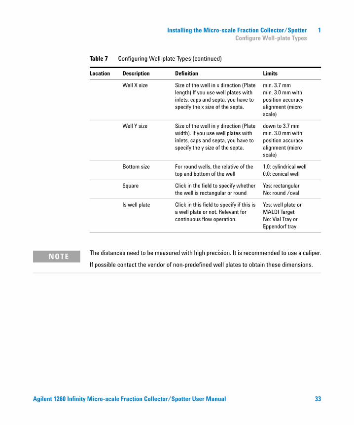
Well X size Size of the well in x direction (Plate length) If you use well plates with inlets, caps and septa, you have to specify the x size of the septa.
min. 3.7 mmmin. 3.0 mm with position accuracy alignment (micro scale)
Well Y size Size of the well in y direction (Plate width). If you use well plates with inlets, caps and septa, you have to specify the y size of the septa.
down to 3.7 mmmin. 3.0 mm with position accuracy alignment (micro scale)
Bottom size For round wells, the relative of the top and bottom of the well
1.0: cylindrical well0.0: conical well
Square Click in the field to specify whether the well is rectangular or round
Yes: rectangularNo: round /oval
Is well plate Click in this field to specify if this is a well plate or not. Relevant for continuous flow operation.
Yes: well plate or MALDI TargetNo: Vial Tray or Eppendorf tray
Table 7 Configuring Well-plate Types (continued)
Location Description Definition Limits
NOTE The distances need to be measured with high precision. It is recommended to use a caliper.
If possible contact the vendor of non-predefined well plates to obtain these dimensions.
Agilent 1260 Infinity Micro-scale Fraction Collector/Spotter User Manual 33
1 Installing the Micro-scale Fraction Collector/SpotterTransporting the Micro-scale Collector Spotter
Transporting the Micro-scale Collector Spotter
When moving the Agilent 1260 Infinity Micro- scale Fraction Collector/Spotter inside the laboratory, no special precautions are needed. However, if the micro- scale fraction collector/spotter needs to be shipped to another location via carrier, ensure:
✔ The transport assembly is in the park position. Use the ChemStation or the Agilent Instant Pilot G4208A for this command.
To move the arm to the park position:
1 Switch to the Diagnosis view of the ChemStation and select Fraction Collector > Maintenance Positions. from the Maintenance menu
2 In the upcoming dialog box click Park Arm.
✔ The vial tray and the sample transport mechanism is secured with the transport protection foam.
34 Agilent 1260 Infinity Micro-scale Fraction Collector/Spotter User Manual
Agilent 1260 Infinity Series Micro-scale Fraction Collector/SpotterUser Manual
2Configuration and Operation of the Micro-scale Fraction Collector/Spotter
Introduction 36
Initialization and Reset 39
Configuration of the Micro-scale Fraction Collector/Spotter 40
Setting up a Micro-scale Fraction Collector/Spotter Method 49
Viewing your Results 60
Check-out Procedures 66
35Agilent Technologies
2 Configuration and Operation of the Micro-scale Fraction Collector/SpotterIntroduction
Introduction
The Agilent 1260 Infinity Micro- scale Fraction Collector/Spotter G1364D is an instrument for micro- scale fraction collection or MALDI Spotting with the Agilent 1260 Infinity Capillary or Nanoflow LC Systems. With these systems the collection of very low volume fractions requires
• low delay volumes.
• high position accuracy of the capillary tip.
• liquid contact control for reproducible collection of small fractions without carryover.
The principles of operation for the Agilent 1260 Infinity Micro- scale Fraction Collector/Spotter will be illustrated in this chapter along with detailed descriptions on how to set up the method and change the configuration. This will enable the user to run the instrument with optimal performance.
The Agilent 1260 Infinity Micro- scale Fraction Collector/Spotter designed for low flow rates from below 100 µl/min down to 100nl/min. In order to keep dispersion a single low volume PEEK coated fused silica capillary is used to direct the flow to the vessel or MALDI target. A permanent waste position is built in to allow automated and continuous collection of the eluent.
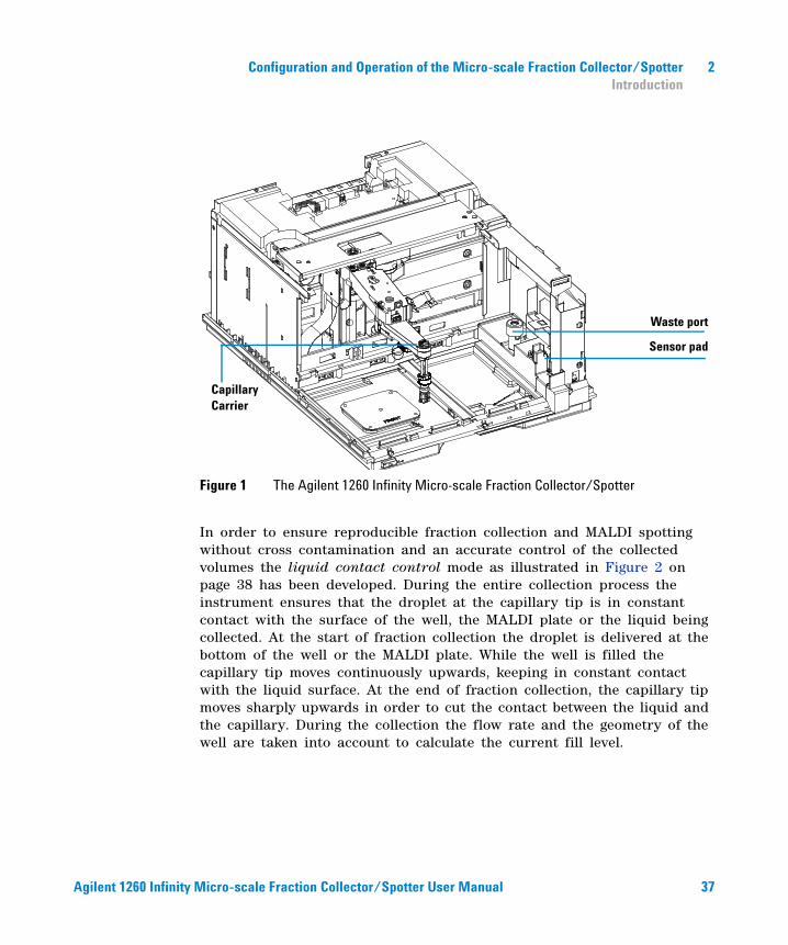
The proper alignment of the capillary tip is crucial for precise collection of the fractions, especially if 384 conical- well plates or MALDI targets are used. A sensor pad for automated control of the capillary tip position was therefore integrated into the micro- scale fraction collector/spotter. A diagram of the fraction collector, which indicates the most important components, is shown in Figure 1 on page 37
36 Agilent 1260 Infinity Micro-scale Fraction Collector/Spotter User Manual
Configuration and Operation of the Micro-scale Fraction Collector/Spotter 2Introduction
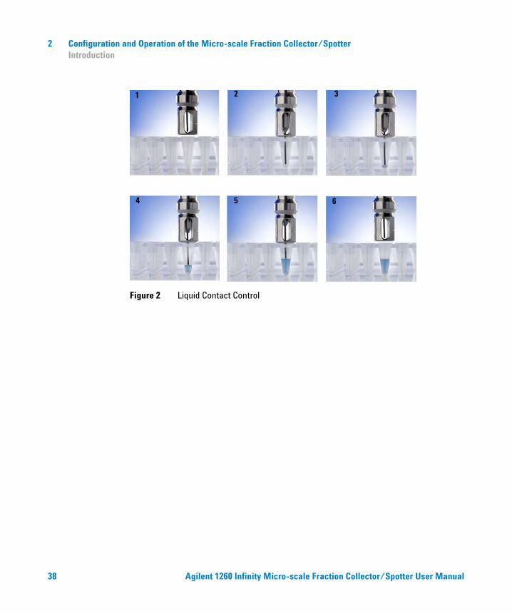
In order to ensure reproducible fraction collection and MALDI spotting without cross contamination and an accurate control of the collected volumes the liquid contact control mode as illustrated in Figure 2 on page 38 has been developed. During the entire collection process the instrument ensures that the droplet at the capillary tip is in constant contact with the surface of the well, the MALDI plate or the liquid being collected. At the start of fraction collection the droplet is delivered at the bottom of the well or the MALDI plate. While the well is filled the capillary tip moves continuously upwards, keeping in constant contact with the liquid surface. At the end of fraction collection, the capillary tip moves sharply upwards in order to cut the contact between the liquid and the capillary. During the collection the flow rate and the geometry of the well are taken into account to calculate the current fill level.
Figure 1 The Agilent 1260 Infinity Micro-scale Fraction Collector/Spotter
Waste port
Sensor pad
Capillary Carrier
Agilent 1260 Infinity Micro-scale Fraction Collector/Spotter User Manual 37
2 Configuration and Operation of the Micro-scale Fraction Collector/SpotterIntroduction
Figure 2 Liquid Contact Control
1 2 3
4 5 6
38 Agilent 1260 Infinity Micro-scale Fraction Collector/Spotter User Manual
Configuration and Operation of the Micro-scale Fraction Collector/Spotter 2Initialization and Reset
Initialization and Reset
After power- on the instrument delays the initialization for approximately two minutes to vent the fraction compartment. Then the door lock is activated and the micro- scale fraction collector/spotter remains in the not ready condition (yellow) waiting for the manual reset.
Before you reset the micro- scale fraction collector/spotter the door has to be closed. To reset the instrument click on the micro- scale fraction collector/spotter icon in the graphical user interface of the ChemStation and start the Reset. If the main pump is switched ON, a dialog is displayed, which reminds the user to switch OFF the pump. Then the reset procedure is started without the risk of contaminating well plates or fractions.
During the initialization process the vertical and the horizontal position of the capillary tip is determined. The micro- scale fraction collector/spotter performs the capillary check by pressing the capillary tip onto the sensor pad. After this capillary check a message is displayed, if any further capillary alignment is required. For more details about capillary alignment refer to “Choosing and Installing the Micro- scale Fraction Collector/Spotter Capillary” on page 40.
Switching the Micro-scale Fraction Collector/Spotter Lamp
The micro- scale fraction collector/spotter includes a lamp to illuminate the fraction compartment. The lamp is specifically required for the position accuracy calibration as described on page 82 and page 84.
The operation of the lamp requires firmware revision A.05.09 or higher and ChemStation revision A.10.02 or higher. To activate the lamp switch open the command line in the ChemStation and type:
microafclampon to switch the lamp ONmicroafclampoff to switch the lamp OFF
Agilent 1260 Infinity Micro-scale Fraction Collector/Spotter User Manual 39
2 Configuration and Operation of the Micro-scale Fraction Collector/SpotterConfiguration of the Micro-scale Fraction Collector/Spotter
Configuration of the Micro-scale Fraction Collector/Spotter
Choosing and Installing the Micro-scale Fraction Collector/Spotter Capillary
The micro- scale fraction collector/spotter is delivered with three capillaries each having a different inner diameter: 25, 50 and 100 µm. The 50 µm capillary is installed in the micro- scale fraction collector/spotter, whereas the 25 and the 100 µm capillaries are in the accessory kit (see “Micro- scale Fraction Collector/Spotter Accessory Kit” on page 119).
To optimize the micro- scale fraction collector/spotter for different flow ranges the correct capillary has to be selected and installed.
For micro-scale fraction collection we recommend:
• flow rates below 4 µL/min.: the yellow 25 µm i.d. capillary G1364- 87304 (delay volume app. 0.25 µL)
• flow rates between 4 and 30 µL/min.: the green 50 µm i.d. capillary G1364- 87305 (delay volume app. 1 µL)
• flow rates between 30 and 100 µL/min.: the black 100 µm i.d. capillary G1364- 87306 (delay volume app. 4 µL)
For MALDI spotting we recommend:
• for overall flow rates (LC flow + matrix flow) < 8 μl/min.: the green 50 μm i.d. capillary G1364- 87305 (delay volume app. 1 µL)
• for overall flow rates (LC flow + matrix flow) > 8 μl/min.: the black 100 μm ID capillary G1364- 87306 (delay volume app. 4 µL)
The exchange procedure is described in “Replacing Micro- scale Fraction Collector/Spotter Capillary Assembly” on page 100. An Exchange of the fraction collector capillary might also be necessary, if the capillary is bent or blocked by particles.
40 Agilent 1260 Infinity Micro-scale Fraction Collector/Spotter User Manual
Configuration and Operation of the Micro-scale Fraction Collector/Spotter 2Configuration of the Micro-scale Fraction Collector/Spotter
Adjusting the Peakwidth of Your Detector
When using capillaries in these flow ranges for peak- based fraction collection a Peakwidth of 0.1 min. (Responsetime < 2s) or less should be selected to ensure a fast signal processing. Otherwise the compound might already be flushed through the micro- scale fraction collector/spotter when the peak is detected. If a smaller peakwidth is set the flow rate ranges can be increased.
Capillary Alignment for Micro-scale Fraction Collection
During the initialization process the vertical and the horizontal position of the capillary tip is determined. The micro- scale fraction collector/spotter facilitates the capillary check by pressing the capillary onto the sensor pad. Then the relative capillary length as well as the degree to which the end of the capillary is bent is determined. 384- well plates require a higher position accuracy than 96- well plates. Consequently, a slightly bent capillary might be tolerated for 96- well plates, whereas 384- well plates require the installation of a new capillary or a position accuracy calibration as described in “Position Accuracy Calibration for 384- Well Plates” on page 82. After the capillary check procedure a message is displayed, if any further capillary alignment is required.
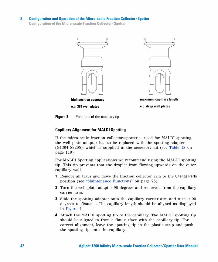
The capillary length has to be adjusted between the following limits (see Figure 3):
• For 384- conical- well plates (PCR plates) where high position accuracy is required the capillary tip should be approximately set to the groove at the center of the well- plate adapter.
• When 96- well plates or deep 384- well plates are used the capillary tip must be set to the lower edge of the well- plate adapter opening in order to reach the bottom of the wells.
CAUTION If solvents with high concentrations of matrix, buffer or salt are used, the capillary has to be flushed thoroughly with salt free water after analysis. Such a procedure prevents the capillary and the waste port from clogging.
Agilent 1260 Infinity Micro-scale Fraction Collector/Spotter User Manual 41
2 Configuration and Operation of the Micro-scale Fraction Collector/SpotterConfiguration of the Micro-scale Fraction Collector/Spotter
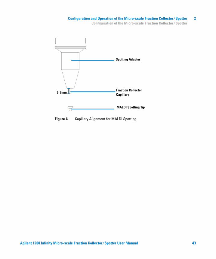
Capillary Alignment for MALDI Spotting
If the micro- scale fraction collector/spotter is used for MALDI spotting, the well- plate adapter has to be replaced with the spotting adapter (G1364- 83205), which is supplied in the accessory kit (see Table 18 on page 119).
For MALDI Spotting applications we recommend using the MALDI spotting tip. This tip prevents that the droplet from flowing upwards on the outer capillary wall.
1 Remove all trays and move the fraction collector arm to the Change Parts position (see “Maintenance Functions” on page 75).
2 Turn the well- plate adapter 90 degrees and remove it from the capillary carrier arm.
3 Slide the spotting adapter onto the capillary carrier arm and turn it 90 degrees to fixate it. The capillary length should be aligned as displayed in Figure 4.
4 Attach the MALDI spotting tip to the capillary. The MALDI spotting tip should be aligned to from a flat surface with the capillary tip. For correct alignment, leave the spotting tip in the plastic strip and push the spotting tip onto the capillary.
Figure 3 Positions of the capillary tip
high position accuracy
e.g. 384 well plates
maximum capillary length
e.g. deep well plates
42 Agilent 1260 Infinity Micro-scale Fraction Collector/Spotter User Manual
Configuration and Operation of the Micro-scale Fraction Collector/Spotter 2Configuration of the Micro-scale Fraction Collector/Spotter
Figure 4 Capillary Alignment for MALDI Spotting
Spotting Adapter
Fraction Collector Capillary
MALDI Spotting Tip
5-7mm
Agilent 1260 Infinity Micro-scale Fraction Collector/Spotter User Manual 43
2 Configuration and Operation of the Micro-scale Fraction Collector/SpotterConfiguration of the Micro-scale Fraction Collector/Spotter
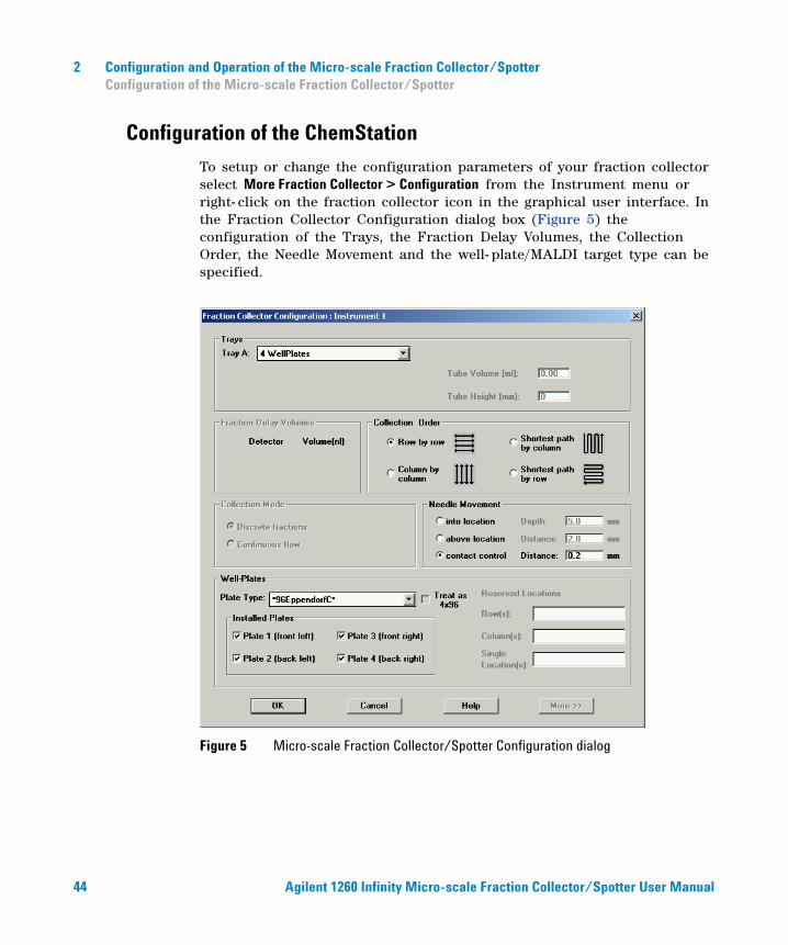
Configuration of the ChemStation
To setup or change the configuration parameters of your fraction collector select More Fraction Collector > Configuration from the Instrument menu or right- click on the fraction collector icon in the graphical user interface. In the Fraction Collector Configuration dialog box (Figure 5) the configuration of the Trays, the Fraction Delay Volumes, the Collection Order, the Needle Movement and the well- plate/MALDI target type can be specified.
Figure 5 Micro-scale Fraction Collector/Spotter Configuration dialog
44 Agilent 1260 Infinity Micro-scale Fraction Collector/Spotter User Manual
Configuration and Operation of the Micro-scale Fraction Collector/Spotter 2Configuration of the Micro-scale Fraction Collector/Spotter
Trays
In the online ChemStation the configuration of the Trays is recognized automatically. In the offline ChemStation the tray configuration can be chosen in a dropdown menu.
Fraction Delay Volumes
The fraction delay volumes specify the volume between the detector cell and fraction collector capillary tip. This volume is required to calculate the time delay between the detection of the peak in the detector and the start of the collection in the fraction collector. For the micro- scale fraction collector/spotter G1364D this volume depends on the installed capillaries. The fraction delay volume can be calculated by:
fraction delay volume = volume (detector outlet capillary) + volume (fraction collector inlet capillary)
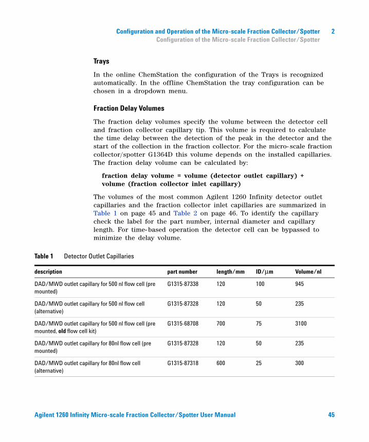
The volumes of the most common Agilent 1260 Infinity detector outlet capillaries and the fraction collector inlet capillaries are summarized in Table 1 on page 45 and Table 2 on page 46. To identify the capillary check the label for the part number, internal diameter and capillary length. For time- based operation the detector cell can be bypassed to minimize the delay volume.
Table 1 Detector Outlet Capillaries
description part number length/mm ID/μm Volume/nl
DAD/MWD outlet capillary for 500 nl flow cell (pre mounted)
G1315-87338 120 100 945
DAD/MWD outlet capillary for 500 nl flow cell (alternative)
G1315-87328 120 50 235
DAD/MWD outlet capillary for 500 nl flow cell (pre mounted, old flow cell kit)
G1315-68708 700 75 3100
DAD/MWD outlet capillary for 80nl flow cell (pre mounted)
G1315-87328 120 50 235
DAD/MWD outlet capillary for 80nl flow cell (alternative)
G1315-87318 600 25 300
Agilent 1260 Infinity Micro-scale Fraction Collector/Spotter User Manual 45
2 Configuration and Operation of the Micro-scale Fraction Collector/SpotterConfiguration of the Micro-scale Fraction Collector/Spotter
Collection Order
The Collection Order describes capillary movement during fraction collection. Four different strategies are possible: row- by- row and column- by- column either in one direction or in two directions.
Collection Mode
Selection of the Collection Mode is not available for the micro- scale fraction collector/spotter and therefore greyed out in this configuration. The micro- scale fraction collector/spotter always operates in the continuous flow mode.
Needle Movement
Into location In the into location mode the capillary tip moves into the well to the specified Depth (in mm).
Above location In the above location mode the capillary tip stays at the specified Distance (in mm) above the well during fraction collection.
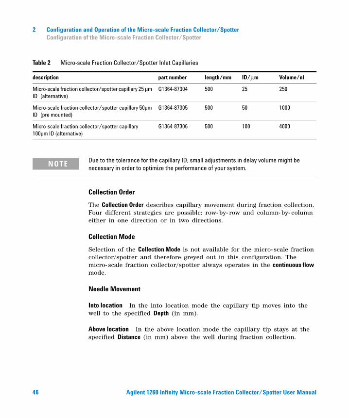
Table 2 Micro-scale Fraction Collector/Spotter Inlet Capillaries
description part number length/mm ID/μm Volume/nl
Micro-scale fraction collector/spotter capillary 25 µm ID (alternative)
G1364-87304 500 25 250
Micro-scale fraction collector/spotter capillary 50µm ID (pre mounted)
G1364-87305 500 50 1000
Micro-scale fraction collector/spotter capillary 100µm ID (alternative)
G1364-87306 500 100 4000
NOTE Due to the tolerance for the capillary ID, small adjustments in delay volume might be necessary in order to optimize the performance of your system.
46 Agilent 1260 Infinity Micro-scale Fraction Collector/Spotter User Manual
Configuration and Operation of the Micro-scale Fraction Collector/Spotter 2Configuration of the Micro-scale Fraction Collector/Spotter
Contact Control In this mode the capillary tip moves down until is reaches the specified distance between capillary tip and well bottom. This ensures that the forming droplet is in contact with the well bottom. During the continuing filling process the capillary tip moves upwards while staying in contact with the surface of the collected liquid.
For low flow rates (< 1 μl/min) a small Distance (<0.2 mm) should be chosen. This value should be increased to 0.3- 0.7 mm in particular for MALDI spotting at higher flow rates.
Well Plates
In the Well Plates section the type of well plates or MALDI targets used in a well plate tray can be configured. The well plate type used can be chosen from the Plate Type dropdown menu. More detailed information about all preconfigured well plates and MALDI targets can be found in the Instrument menu. A list of recommended Agilent well plates can be found in Table 11 on page 112 and a list of supported MALDI targets is available in Table 15 on page 115. To configure other well plates or MALDI targets choose Configure Well Plates from the Instrument menu.
If the well plate tray is loaded with multiple well plates or vial plates, all plates have to be of the same type (e.g. 4 x Agilent conical 96 well plate).
The checkbox Treat as 4 x 96 is only available for 384 well plates and allows splitting the 384 well plate virtually into 4 separate 96- well plates. This only changes the collection order, but the numbering of the wells remains as indicated on the plate. The filling order of each quarter is as specified in the Collection Order section. When the 384 well plate is split into four
NOTE The capillary movement in the Contact Control mode depends on the flow rate that is delivered by the Agilent 1260 Infinity pump. If your LC system contains more than one pump, the flow rate of the first pump in your system determines the needle movement. In this case verify in your system configuration (Instrument > Configure 1260 access) that this pump is the first one in the Configured Modules list. In addition this pump should also be selected as main pump (Instrument > Change main pump).
NOTE Note the orientation of the well plate or the MALDI plate. The starting position A1 is always at the back left corner of the plate.
Agilent 1260 Infinity Micro-scale Fraction Collector/Spotter User Manual 47
2 Configuration and Operation of the Micro-scale Fraction Collector/SpotterConfiguration of the Micro-scale Fraction Collector/Spotter
equal quarters the order of the four plates is the same as displayed in the Installed Plates section. Each tray position that contains a well plate has to be checked.
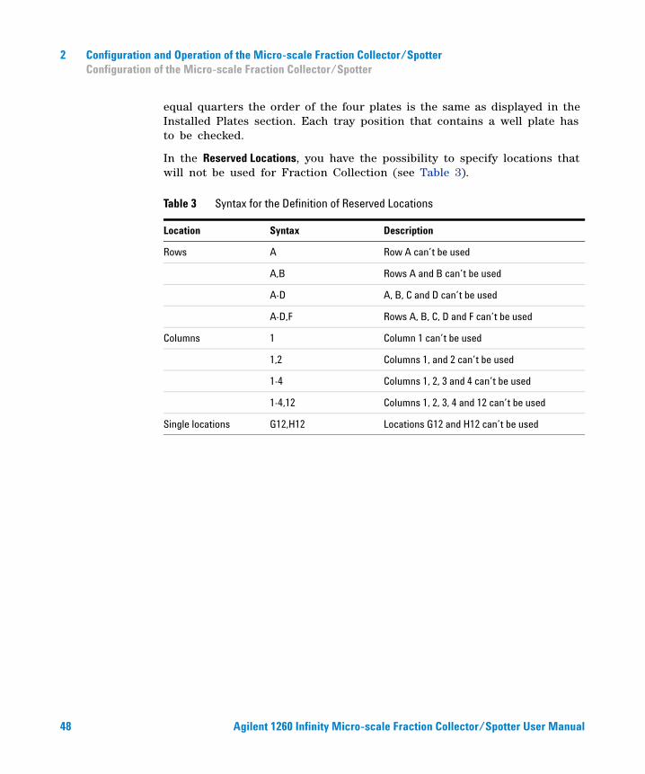
In the Reserved Locations, you have the possibility to specify locations that will not be used for Fraction Collection (see Table 3).
Table 3 Syntax for the Definition of Reserved Locations
Location Syntax Description
Rows A Row A can’t be used
A,B Rows A and B can’t be used
A-D A, B, C and D can’t be used
A-D,F Rows A, B, C, D and F can’t be used
Columns 1 Column 1 can’t be used
1,2 Columns 1, and 2 can’t be used
1-4 Columns 1, 2, 3 and 4 can’t be used
1-4,12 Columns 1, 2, 3, 4 and 12 can’t be used
Single locations G12,H12 Locations G12 and H12 can’t be used
48 Agilent 1260 Infinity Micro-scale Fraction Collector/Spotter User Manual
Configuration and Operation of the Micro-scale Fraction Collector/Spotter 2Setting up a Micro-scale Fraction Collector/Spotter Method
Setting up a Micro-scale Fraction Collector/Spotter Method
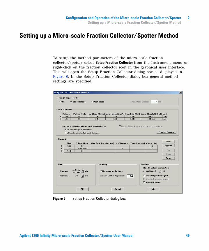
To setup the method parameters of the micro- scale fraction collector/spotter select Setup Fraction Collector from the Instrument menu or right- click on the fraction collector icon in the graphical user interface. This will open the Setup Fraction Collector dialog box as displayed in Figure 6. In the Setup Fraction Collector dialog box general method settings are specified.
Figure 6 Set up Fraction Collector dialog box
Agilent 1260 Infinity Micro-scale Fraction Collector/Spotter User Manual 49
2 Configuration and Operation of the Micro-scale Fraction Collector/SpotterSetting up a Micro-scale Fraction Collector/Spotter Method
Fraction Trigger Mode
The Fraction Trigger Mode can either be Use Timetable or Peak-based can be selected. Furthermore for the Peak- based mode a time for Maximum Peak Duration can be specified. When the Peak- based mode is chosen, it overrules all settings in the Timetable. If the LC system is used for analytical chromatography without fraction collection or MALDI spotting, the micro- scale fraction collector/spotter can be switched Off.
Peak Detectors
The Peak Detectors section in this screen comprises a list of all Peak Detectors connected to the system. As working modes for each peak detector Threshold only, Threshold/Slope and Slope only are possible. In the Threshold only mode the settings for Up Slope, Down Slope and Upper Threshold in the subsequent columns are ignored. Fraction collection is triggered whenever the detector signal exceeds the specified threshold value. When the signal drops below the threshold value fraction collection is stopped. In the Slope only mode fraction collection is triggered on the slopes of the detector signals. Adequate values for Up Slope and Down Slope can be specified in the corresponding fields. In the Threshold/Slope mode fraction collection is triggered on the corresponding values for threshold and slope. For more detailed information concerning working with threshold and slopes please refer to Agilent’s Application Note “Sophisticated peak- based fraction collection – working with up and down slope” publication number 5988- 7895EN.
The option to specify an Upper Threshold becomes important, if the absorbance exceeds the linear range of the UV-Vis detector. At high absorbance values the light intensity on the detector is extremely low and consequently detector noise will superimpose the detector signal. In this case the detector noise might lead to wrong trigger commands for the micro- scale fraction collector/spotter. As soon as the detector signal exceeds the Upper Threshold, settings for slopes will be ignored until the signal drops again below the Upper Threshold.
CAUTION The spot size for MALDI spotting is specified by the flow rate and the collection time. If peak-based trigger mode is selected for MALDI spotting, the collection time and therefore the spot size is flexible. In this case we recommend specifying a maximum fill volume per location as described in “Auxiliary” on page 53.
50 Agilent 1260 Infinity Micro-scale Fraction Collector/Spotter User Manual
Configuration and Operation of the Micro-scale Fraction Collector/Spotter 2Setting up a Micro-scale Fraction Collector/Spotter Method
When using more than one peak detector fraction collection can be triggered either when all selected peak detectors detect a peak or when at least one selected peak detector detects a peak based on the settings in the detector table.
The Timetable can be used to program changes in the Fraction Trigger Mode during the analysis by entering a time in the Time field and appropriate values in the fields of the timetable. The trigger modes can be specified as Off, Peak- based and Time- based. Time ranges can be defined for the different trigger modes In the column headed Time. If the Off mode is selected, no fractions are collected.
Whenever the Peak- based mode is specified fractions will be collected based on the peak detection parameters given in the Peak Detector table. Additionally a Maximum Peak Duration in minutes has to be specified. This parameter can be used to stop the fraction collection in cases where the baseline drifts, and the signal does not drop below the specified threshold value. The limits are from 0.1 min. to 9999.0 min. This parameter is mandatory if you use Peak Controlled fraction collection, but is disabled for Time Based fraction collection.
Timetable
When the Time-based mode is chosen two different options are available:
• A specific number of fractions or time slices can be specified. The # of Fractions refer to the number of fractions that are collected in the corresponding time frame in the table. This parameter is applicable only for time- based fraction collection. The maximum spotting rate is20 spots/min.
• Alternatively time slices can be set- up that define the collection time for each fraction. This parameter is only available in the time- based fraction collection mode. Based on the maximum spotting rate of 20 spots per minute the minimum time slice for one spot is 3s.
• Contact Adj is a parameter, which is only required for MALDI Spotting. For details please read “Contact Control Adjustment” on page 52.
To edit the Timetable, the functions Insert, Append, Cut, Copy and Paste are available.
To access the additional sections in the Setup Fraction Collector dialog box click the More button.
Agilent 1260 Infinity Micro-scale Fraction Collector/Spotter User Manual 51
2 Configuration and Operation of the Micro-scale Fraction Collector/SpotterSetting up a Micro-scale Fraction Collector/Spotter Method
Recovery
If the Recovery on the Track mode is checked, the solvent that is delivered between the fractions/spots is collected on the same plate for recovery. The capillary carrier will move to the next well following collection order, e.g. row- by- row.
In the Data Analysis view as well as in the Report a fraction list indicates the wells that contain fractions and the wells that contain recovery. With this information the user is able to recover compounds that weren’t collected.
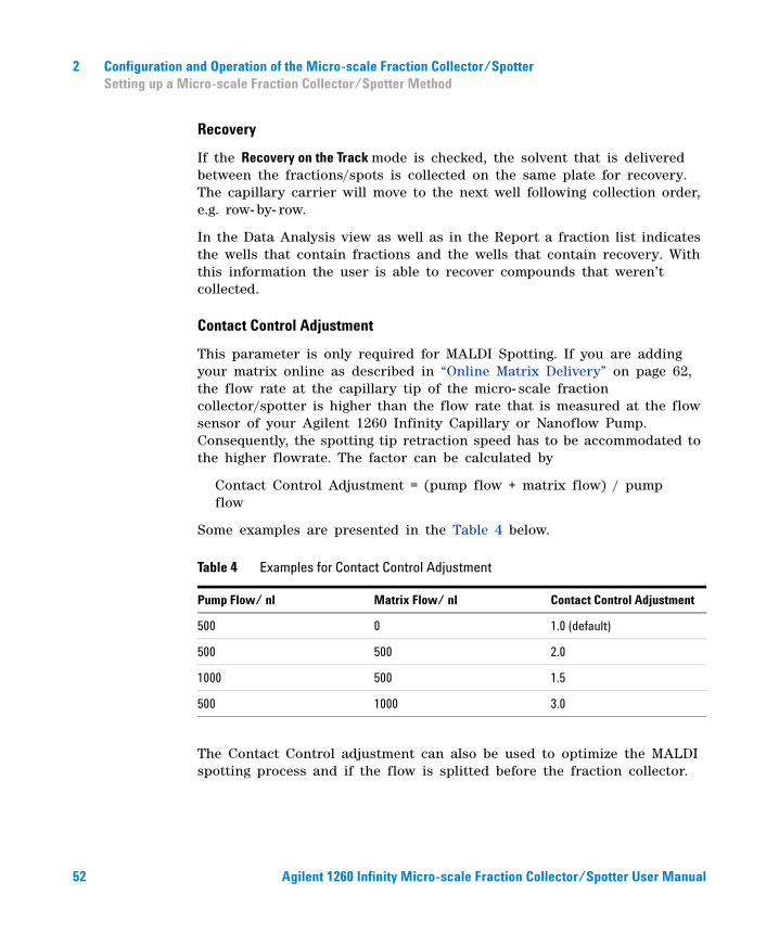
Contact Control Adjustment
This parameter is only required for MALDI Spotting. If you are adding your matrix online as described in “Online Matrix Delivery” on page 62, the flow rate at the capillary tip of the micro- scale fraction collector/spotter is higher than the flow rate that is measured at the flow sensor of your Agilent 1260 Infinity Capillary or Nanoflow Pump. Consequently, the spotting tip retraction speed has to be accommodated to the higher flowrate. The factor can be calculated by
Contact Control Adjustment = (pump flow + matrix flow) / pump flow
Some examples are presented in the Table 4 below.
The Contact Control adjustment can also be used to optimize the MALDI spotting process and if the flow is splitted before the fraction collector.
Table 4 Examples for Contact Control Adjustment
Pump Flow/ nl Matrix Flow/ nl Contact Control Adjustment
500 0 1.0 (default)
500 500 2.0
1000 500 1.5
500 1000 3.0
52 Agilent 1260 Infinity Micro-scale Fraction Collector/Spotter User Manual
Configuration and Operation of the Micro-scale Fraction Collector/Spotter 2Setting up a Micro-scale Fraction Collector/Spotter Method
Auxiliary
In the Auxiliary section the Maximum fill volume per location can be specified. If as configured is selected, the pre- configured volume (see Instrument > Pre-configured Wellplate Types) is used. This ensures that the location (well, vial or tube) cannot be overfilled during fraction collection. This volume can be further reduced by defining a customized volume.
By default all MALDI plates are configured with an infinite fill volume. The Maximum fill volume can be used to determine a maximum spot size, if the peak- based trigger mode is used.
Additional check boxes in this section provide the opportunity to Store the temperature signal and the UIB signal.
Fraction Preview
To determine the appropriate fraction collection parameters the Agilent ChemStation provides a valuable tool that becomes accessible by selecting the button labelled Fraction Preview Tool (Figure 7) in the Peak Detectors section.
Agilent 1260 Infinity Micro-scale Fraction Collector/Spotter User Manual 53
2 Configuration and Operation of the Micro-scale Fraction Collector/SpotterSetting up a Micro-scale Fraction Collector/Spotter Method
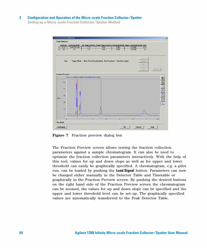
The Fraction Preview screen allows testing the fraction collection parameters against a sample chromatogram. It can also be used to optimize the fraction collection parameters interactively. With the help of this tool, values for up and down slope as well as for upper and lower threshold can easily be graphically specified. A chromatogram, e.g. a pilot run, can be loaded by pushing the Load Signal button. Parameters can now be changed either manually in the Detector Table and Timetable or graphically in the Fraction Preview screen. By pushing the desired buttons on the right hand side of the Fraction Preview screen the chromatogram can be zoomed, the values for up and down slope can be specified and the upper and lower threshold level can be set- up. The graphically specified values are automatically transferred to the Peak Detector Table.
Figure 7 Fraction preview dialog box
54 Agilent 1260 Infinity Micro-scale Fraction Collector/Spotter User Manual
Configuration and Operation of the Micro-scale Fraction Collector/Spotter 2Setting up a Micro-scale Fraction Collector/Spotter Method
Starting Your Run with Fraction Collection or MALDI Spotting
Resetting the current fill levels
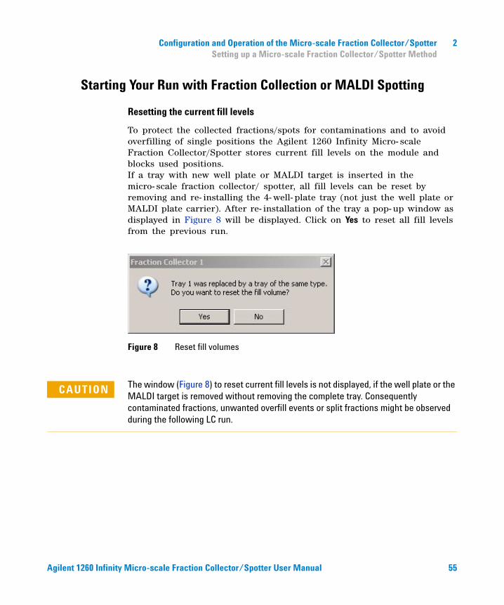
To protect the collected fractions/spots for contaminations and to avoid overfilling of single positions the Agilent 1260 Infinity Micro- scale Fraction Collector/Spotter stores current fill levels on the module and blocks used positions.If a tray with new well plate or MALDI target is inserted in the micro- scale fraction collector/ spotter, all fill levels can be reset by removing and re- installing the 4- well- plate tray (not just the well plate or MALDI plate carrier). After re- installation of the tray a pop- up window as displayed in Figure 8 will be displayed. Click on Yes to reset all fill levels from the previous run.
Figure 8 Reset fill volumes
CAUTION The window (Figure 8) to reset current fill levels is not displayed, if the well plate or the MALDI target is removed without removing the complete tray. Consequently contaminated fractions, unwanted overfill events or split fractions might be observed during the following LC run.
Agilent 1260 Infinity Micro-scale Fraction Collector/Spotter User Manual 55
2 Configuration and Operation of the Micro-scale Fraction Collector/SpotterSetting up a Micro-scale Fraction Collector/Spotter Method
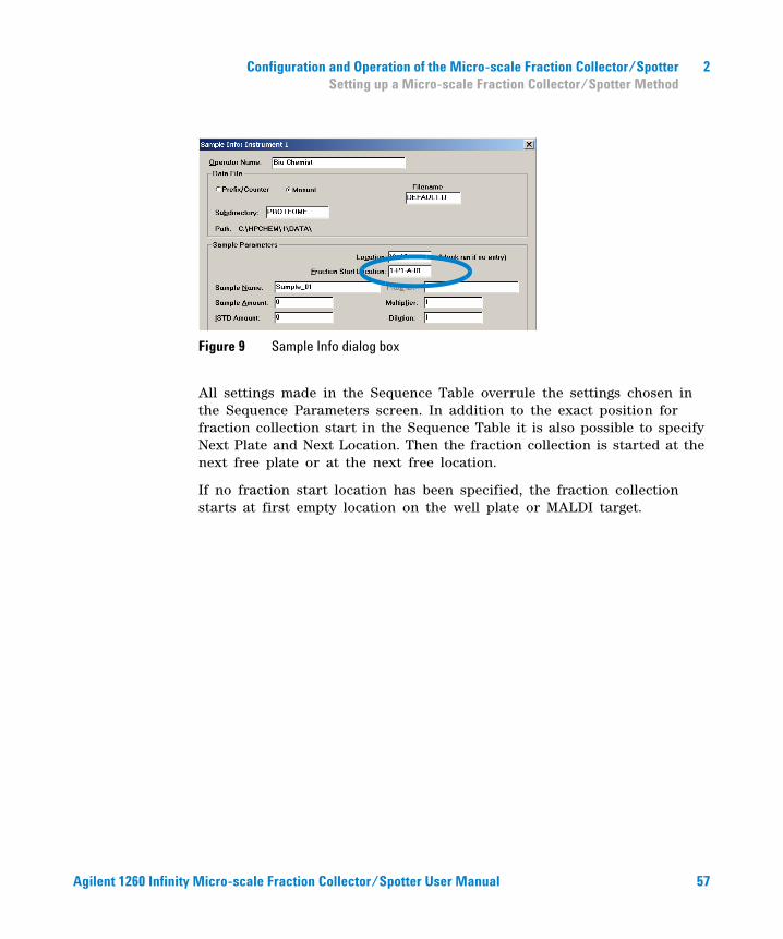
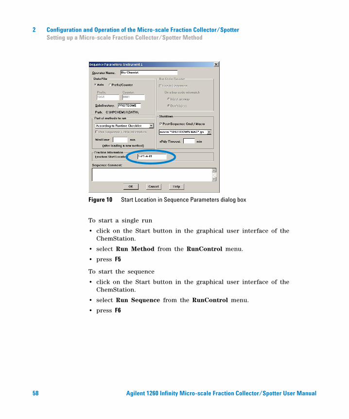
Assignment of Start Location
The start location for fraction collection or MALDI spotting can either be assigned in the Sample Info (Figure 9) dialog box in the RunControl menu, in the Sequence Parameters (Figure 10) dialog box or in the Sequence Table in the Sequence menu. All fraction start locations are entered in the format
micro- scale fraction collector/spotter # - plate number - row - column, e.g. 1-P1-A-01
withmicro- scale fraction collector/spotter # = 1,2; plate number = P1- P4; row is A to H and column = 1- 12 for 96- well plates or the Agilent AP- MALDI plate (for different well plates or MALDI plates refer to the description from the plate manufacturer).
NOTE The run time for a system with a fraction collector must be extended by the delay time, to ensure the complete collection of all compounds.
The run time is calculated as:
run time = end of last peak + delay time(with delay time = delay volume/flow rate)
This calculation is only required, if the flow rate or the delay volume (capillary) is changed. For further info read “Fraction Delay Volumes” on page 45.
NOTE Note the orientation of the MALDI plate. The starting position A1 is always in the back left corner of the plate.
56 Agilent 1260 Infinity Micro-scale Fraction Collector/Spotter User Manual
Configuration and Operation of the Micro-scale Fraction Collector/Spotter 2Setting up a Micro-scale Fraction Collector/Spotter Method
All settings made in the Sequence Table overrule the settings chosen in the Sequence Parameters screen. In addition to the exact position for fraction collection start in the Sequence Table it is also possible to specify Next Plate and Next Location. Then the fraction collection is started at the next free plate or at the next free location.
If no fraction start location has been specified, the fraction collection starts at first empty location on the well plate or MALDI target.
Figure 9 Sample Info dialog box
Agilent 1260 Infinity Micro-scale Fraction Collector/Spotter User Manual 57
2 Configuration and Operation of the Micro-scale Fraction Collector/SpotterSetting up a Micro-scale Fraction Collector/Spotter Method
To start a single run
• click on the Start button in the graphical user interface of the ChemStation.
• select Run Method from the RunControl menu.
• press F5
To start the sequence
• click on the Start button in the graphical user interface of the ChemStation.
• select Run Sequence from the RunControl menu.
• press F6
Figure 10 Start Location in Sequence Parameters dialog box
58 Agilent 1260 Infinity Micro-scale Fraction Collector/Spotter User Manual
Configuration and Operation of the Micro-scale Fraction Collector/Spotter 2Setting up a Micro-scale Fraction Collector/Spotter Method
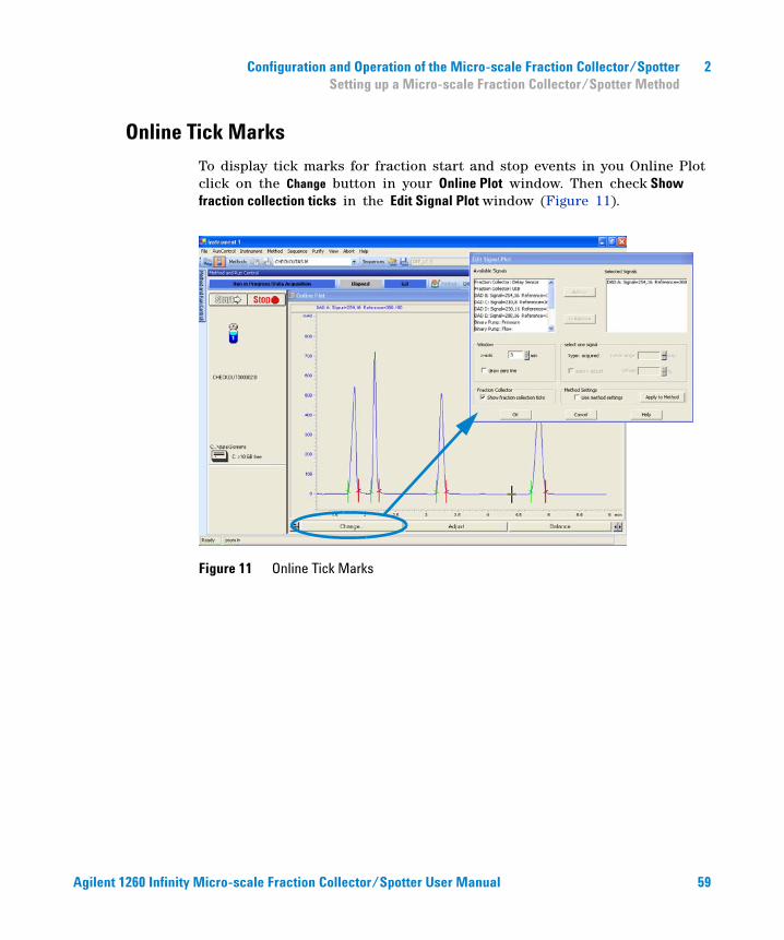
Online Tick Marks
To display tick marks for fraction start and stop events in you Online Plot click on the Change button in your Online Plot window. Then check Show fraction collection ticks in the Edit Signal Plot window (Figure 11).
Figure 11 Online Tick Marks
Agilent 1260 Infinity Micro-scale Fraction Collector/Spotter User Manual 59
2 Configuration and Operation of the Micro-scale Fraction Collector/SpotterViewing your Results
Viewing your Results
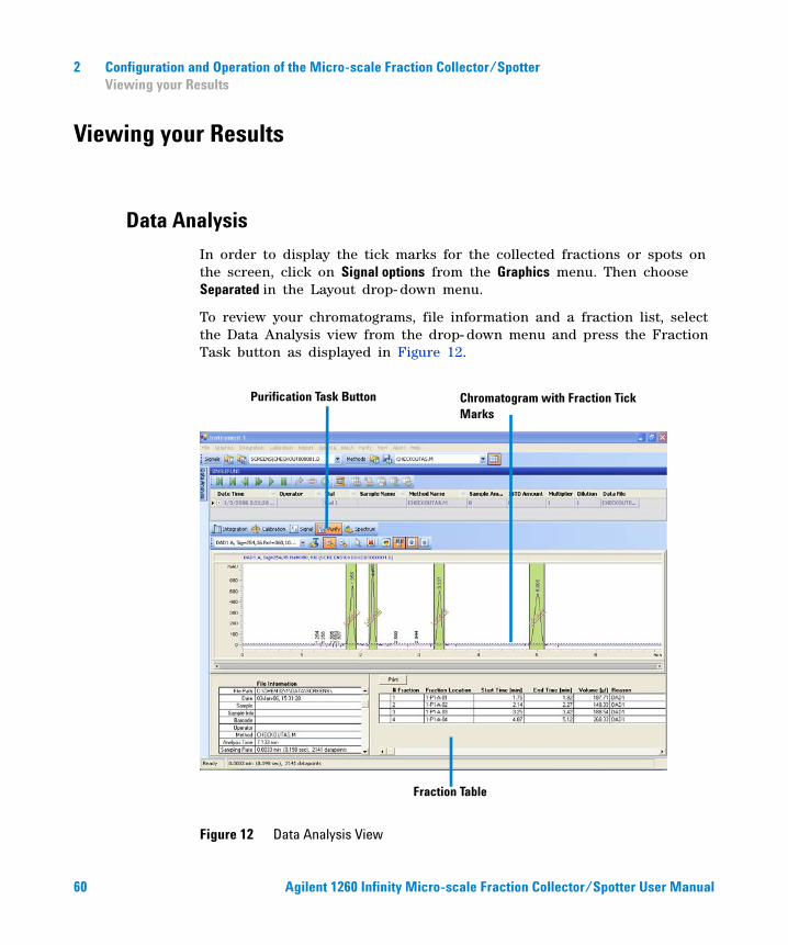
Data Analysis
In order to display the tick marks for the collected fractions or spots on the screen, click on Signal options from the Graphics menu. Then choose Separated in the Layout drop- down menu.
To review your chromatograms, file information and a fraction list, select the Data Analysis view from the drop- down menu and press the Fraction Task button as displayed in Figure 12.
Figure 12 Data Analysis View
Purification Task Button Chromatogram with Fraction Tick Marks
Fraction Table
60 Agilent 1260 Infinity Micro-scale Fraction Collector/Spotter User Manual
Configuration and Operation of the Micro-scale Fraction Collector/Spotter 2Viewing your Results
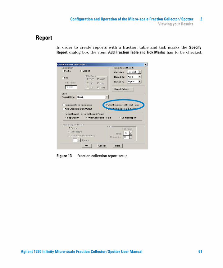
Report
In order to create reports with a fraction table and tick marks the Specify Report dialog box the item Add Fraction Table and Tick Marks has to be checked.
Figure 13 Fraction collection report setup
Agilent 1260 Infinity Micro-scale Fraction Collector/Spotter User Manual 61
2 Configuration and Operation of the Micro-scale Fraction Collector/SpotterOnline Matrix Delivery
Online Matrix Delivery
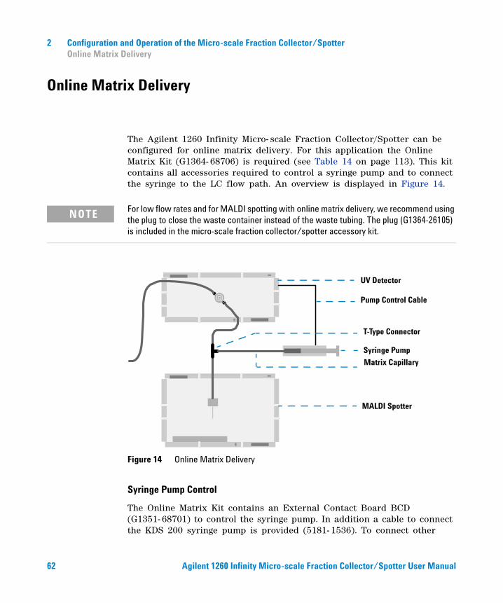
The Agilent 1260 Infinity Micro- scale Fraction Collector/Spotter can be configured for online matrix delivery. For this application the Online Matrix Kit (G1364- 68706) is required (see Table 14 on page 113). This kit contains all accessories required to control a syringe pump and to connect the syringe to the LC flow path. An overview is displayed in Figure 14.
Syringe Pump Control
The Online Matrix Kit contains an External Contact Board BCD (G1351- 68701) to control the syringe pump. In addition a cable to connect the KDS 200 syringe pump is provided (5181- 1536). To connect other
NOTE For low flow rates and for MALDI spotting with online matrix delivery, we recommend using the plug to close the waste container instead of the waste tubing. The plug (G1364-26105) is included in the micro-scale fraction collector/spotter accessory kit.
Figure 14 Online Matrix Delivery
MALDI Spotter
Syringe Pump
Matrix Capillary
T-Type Connector
Pump Control Cable
UV Detector
62 Agilent 1260 Infinity Micro-scale Fraction Collector/Spotter User Manual

Configuration and Operation of the Micro-scale Fraction Collector/Spotter 2Online Matrix Delivery
syringe pumps a general purpose control cable (18594- 60520) can be ordered and configured. The BCD board can be installed in any Agilent 1260 Infinity LC module. For installation details refer to the corresponding service manual.
The pump control can easily be setup in the ChemStation as displayed in Figure 15. To open the dialog box select the module where the external contact board is installed and click on the icon in the graphical user interface. Then select Contacts.
The default setting should be set as open, i.e. the syringe pump is switched off. In the example that is shown in Figure 15 the syringe pump is switched off by default. Using the Timetable the matrix flow can be switched as required during the run. We recommend switching the syringe pump on at least 10 minutes before the start of the LC run in order to prime the matrix capillary and ensure that the matrix is added to the LC flow immediately after the run is started.
Contact 1 is open: syringe pump is switched offContact 1 is closed: syringe pump is switched on
Capillaries and Fittings
The Online Matrix Kit contains:
Figure 15 Syringe Pump Control through External Contacts
Agilent 1260 Infinity Micro-scale Fraction Collector/Spotter User Manual 63
2 Configuration and Operation of the Micro-scale Fraction Collector/SpotterOnline Matrix Delivery
• peek coated fused silica capillary 125 μm ID, 550mm length (G1375- 87318)
• T- type connector (5042- 8519)
• Connector syringe to capillary (5042- 8517)
To setup the flow connections the outlet capillary from the UV detector, the fraction collector capillary and the capillary from the matrix pump have to be connected to the T- type Connector as displayed in Figure 14 on page 62.
We recommend using
• the 50 μm ID fraction collector capillary (G1364- 87305) for overall flow rates (LC flow and matrix flow) < 8 μl/min.
• the 100 μm ID fraction collector capillary (G1364- 87306) for overall flow rates (LC flow and matrix flow) > 8 μl/min.
The peek coated fused silica capillary (125 μm ID, 550mm length) is used to deliver the matrix solution from the syringe to the T- type connector, where it is merged with the flow from the Agilent 1260 Infinity LC System.
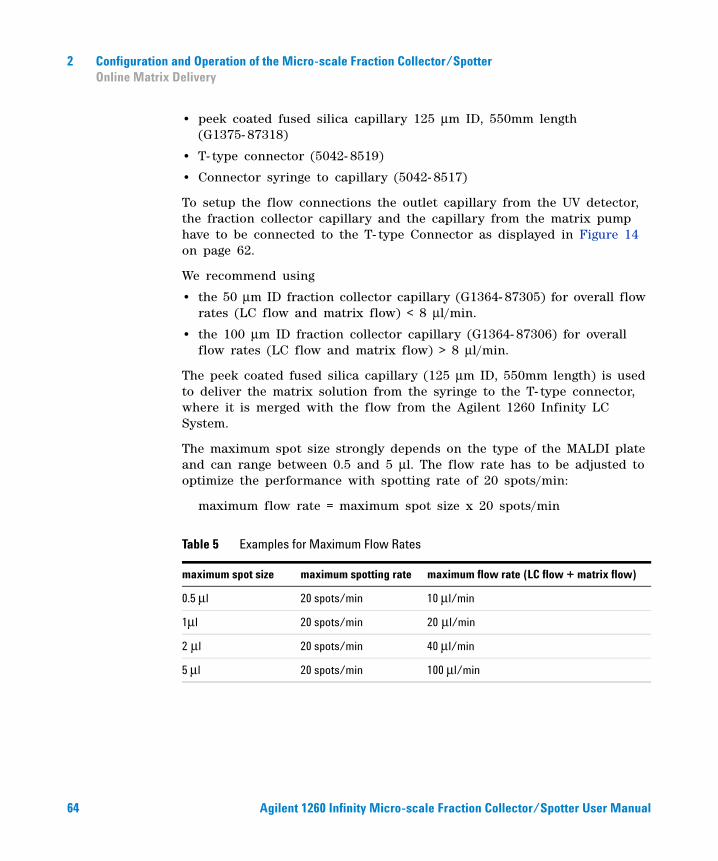
The maximum spot size strongly depends on the type of the MALDI plate and can range between 0.5 and 5 μl. The flow rate has to be adjusted to optimize the performance with spotting rate of 20 spots/min:
maximum flow rate = maximum spot size x 20 spots/min
Table 5 Examples for Maximum Flow Rates
maximum spot size maximum spotting rate maximum flow rate (LC flow + matrix flow)
0.5 μl 20 spots/min 10 μl/min
1μl 20 spots/min 20 μl/min
2 μl 20 spots/min 40 μl/min
5 μl 20 spots/min 100 μl/min
64 Agilent 1260 Infinity Micro-scale Fraction Collector/Spotter User Manual
Configuration and Operation of the Micro-scale Fraction Collector/Spotter 2Online Matrix Delivery
Contact Control Adjustment
If the matrix is added online, the flow that is delivered by the Agilent 1260 Infinity Capillary or Nanoflow Pump is different from the flow at the capillary tip in the MALDI spotter. To account for this additional flow the Contact Control Adjustment has to be specified as described on page 52.
CAUTION If solvents with high concentrations of matrix, buffer or salt are used, the capillary has to be flushed thoroughly with salt free water after analysis. Such a procedure prevents the capillary and the waste port from clogging.
Agilent 1260 Infinity Micro-scale Fraction Collector/Spotter User Manual 65
2 Configuration and Operation of the Micro-scale Fraction Collector/SpotterCheck-out Procedures
Check-out Procedures
The purpose of the check- out injection is the verification of the correct installation and configuration of the Agilent 1260 Infinity Micro- scale Fraction Collector/Spotter system. In addition the checkout procedure can used for troubleshooting, if the Agilent 1260 Infinity Micro- scale Fraction Collector/Spotter doesn’t operate as expected.
The checkout procedure depends on the application and is different for micro fraction collection into well plates and for MALDI spotting.
Check-out Procedure for Micro-scale Fraction Collection
The check- out procedure is based on the procedure for the Agilent 1260 Infinity Capillary LC System. After the check- out sample (01080- 68704) has been injected, four peaks have to be detected and four fractions collected.
Prerequisites
✔ The Agilent 1260 Infinity Capillary LC System has been installed and prepared as described in the Agilent 1260 Infinity Capillary LC System Manual G1376- 90013.
✔ The Agilent 1260 Infinity Micro- scale Fraction Collector/Spotter has been installed and configured. The delay volume has been specified.
✔ A well plate is installed as plate 1 in the 4 well plate tray. If 384 well plates are used, the “Arm Length Calibration” on page 79 and the “Position Accuracy Calibration for 384- Well Plates” on page 82 have to be executed before running the check- out.
✔ All wells are empty and the fill levels, which are stored on the module, have been reset. To verify this remove and insert the 4 well plate tray. Then click on Yes in displayed dialog box.
66 Agilent 1260 Infinity Micro-scale Fraction Collector/Spotter User Manual
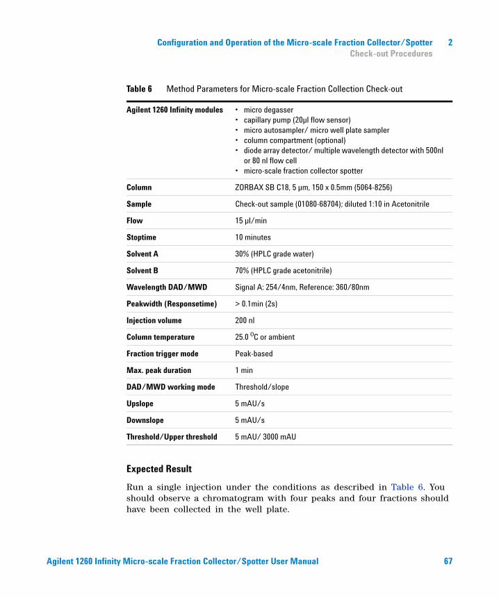
Configuration and Operation of the Micro-scale Fraction Collector/Spotter 2Check-out Procedures
Expected Result
Run a single injection under the conditions as described in Table 6. You should observe a chromatogram with four peaks and four fractions should have been collected in the well plate.
Table 6 Method Parameters for Micro-scale Fraction Collection Check-out
Agilent 1260 Infinity modules • micro degasser• capillary pump (20µl flow sensor)• micro autosampler/ micro well plate sampler• column compartment (optional)• diode array detector/ multiple wavelength detector with 500nl
or 80 nl flow cell• micro-scale fraction collector spotter
Column ZORBAX SB C18, 5 µm, 150 x 0.5mm (5064-8256)
Sample Check-out sample (01080-68704); diluted 1:10 in Acetonitrile
Flow 15 µl/min
Stoptime 10 minutes
Solvent A 30% (HPLC grade water)
Solvent B 70% (HPLC grade acetonitrile)
Wavelength DAD/MWD Signal A: 254/4nm, Reference: 360/80nm
Peakwidth (Responsetime) > 0.1min (2s)
Injection volume 200 nl
Column temperature 25.0 0C or ambient
Fraction trigger mode Peak-based
Max. peak duration 1 min
DAD/MWD working mode Threshold/slope
Upslope 5 mAU/s
Downslope 5 mAU/s
Threshold/Upper threshold 5 mAU/ 3000 mAU
Agilent 1260 Infinity Micro-scale Fraction Collector/Spotter User Manual 67
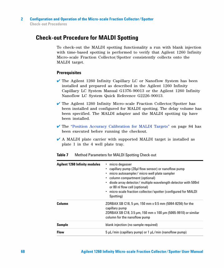
2 Configuration and Operation of the Micro-scale Fraction Collector/SpotterCheck-out Procedures
Check-out Procedure for MALDI Spotting
To check- out the MALDI spotting functionality a run with blank injection with time- based spotting is performed to verify that Agilent 1260 Infinity Micro- scale Fraction Collector/Spotter consistently collects onto the MALDI target.
Prerequisites
✔ The Agilent 1260 Infinity Capillary LC or Nanoflow System has been installed and prepared as described in the Agilent 1260 Infinity Capillary LC System Manual G1376- 90013 or the Agilent 1260 Infinity Nanoflow LC System Quick Reference G2226- 90013.
✔ The Agilent 1260 Infinity Micro- scale Fraction Collector/Spotter has been installed and configured for MALDI spotting. The delay volume has been specified. The MALDI adapter and the MALDI spotting tip have been installed.
✔ The “Position Accuracy Calibration for MALDI Targets” on page 84 has been executed before running the checkout.
✔ A MALDI plate carrier with supported MALDI target is installed as plate 1 in the 4 well plate tray.
Table 7 Method Parameters for MALDI Spotting Check-out
Agilent 1260 Infinity modules • micro degasser• capillary pump (20µl flow sensor) or nanoflow pump• micro autosampler/ micro well plate sampler• column compartment (optional)• diode array detector/ multiple wavelength detector with 500nl
or 80 nl flow cell (optional)• micro-scale fraction collector/spotter (configured for MALDI
Spotting)
Column ZORBAX SB C18, 5 µm, 150 mm x 0.5 mm (5064-8256) for the capillary pumpZORBAX SB C18, 3.5 µm, 150 mm x 100 µm (5065-9910) or similar column for the nanoflow pump
Sample blank injection (no sample required)
Flow 5 µL/min (capillary pump) or 1 µL/min (nanoflow pump)
68 Agilent 1260 Infinity Micro-scale Fraction Collector/Spotter User Manual
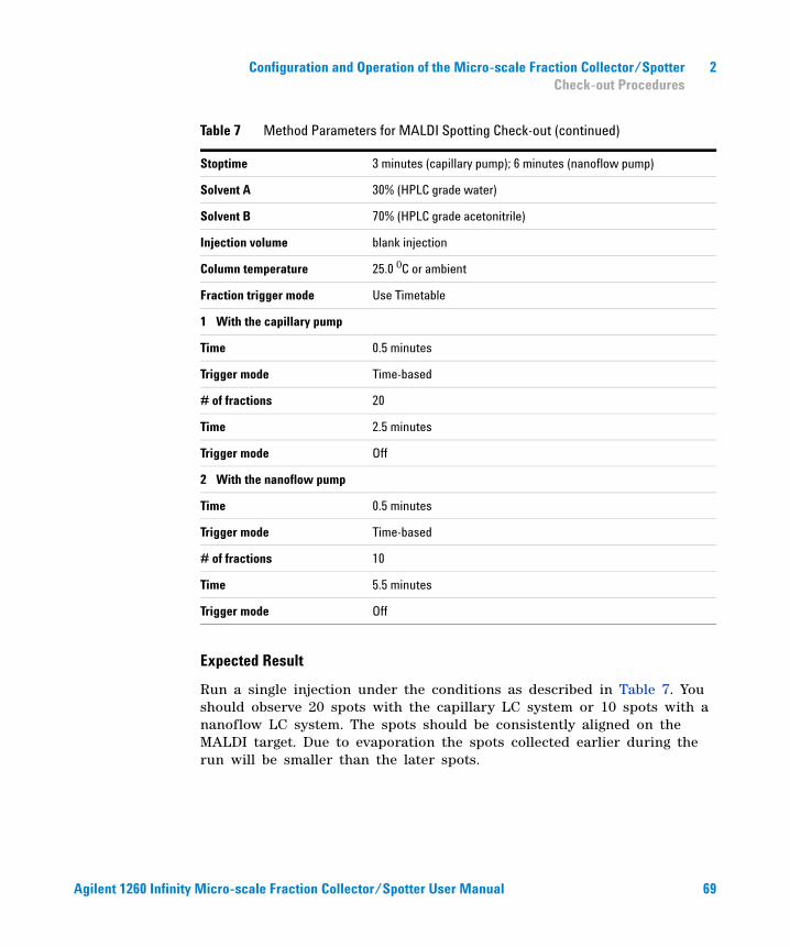
Configuration and Operation of the Micro-scale Fraction Collector/Spotter 2Check-out Procedures
Expected Result
Run a single injection under the conditions as described in Table 7. You should observe 20 spots with the capillary LC system or 10 spots with a nanoflow LC system. The spots should be consistently aligned on the MALDI target. Due to evaporation the spots collected earlier during the run will be smaller than the later spots.
Stoptime 3 minutes (capillary pump); 6 minutes (nanoflow pump)
Solvent A 30% (HPLC grade water)
Solvent B 70% (HPLC grade acetonitrile)
Injection volume blank injection
Column temperature 25.0 0C or ambient
Fraction trigger mode Use Timetable
1 With the capillary pump
Time 0.5 minutes
Trigger mode Time-based
# of fractions 20
Time 2.5 minutes
Trigger mode Off
2 With the nanoflow pump
Time 0.5 minutes
Trigger mode Time-based
# of fractions 10
Time 5.5 minutes
Trigger mode Off
Table 7 Method Parameters for MALDI Spotting Check-out (continued)
Agilent 1260 Infinity Micro-scale Fraction Collector/Spotter User Manual 69
2 Configuration and Operation of the Micro-scale Fraction Collector/SpotterCheck-out Procedures
70 Agilent 1260 Infinity Micro-scale Fraction Collector/Spotter User Manual
Agilent 1260 Infinity Series Micro-scale Fraction Collector/SpotterUser Manual
3Troubleshooting and Test Functions
Status Indicators 72
Deactivating the Door Lock Sensor 74
Maintenance Functions 75
Transport Unit Self Alignment 77
Arm Length Calibration 79
Position Accuracy Calibration for 384-Well Plates 82
Position Accuracy Calibration for MALDI Targets 84
Single Step Commands 87
71Agilent Technologies
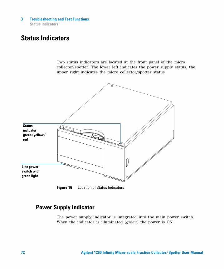
3 Troubleshooting and Test FunctionsStatus Indicators
Status Indicators
Two status indicators are located at the front panel of the micro collector/spotter. The lower left indicates the power supply status, the upper right indicates the micro collector/spotter status.
Power Supply Indicator
The power supply indicator is integrated into the main power switch. When the indicator is illuminated (green) the power is ON.
Figure 16 Location of Status Indicators
Status indicatorgreen/yellow/red
Line power switch with green light
72 Agilent 1260 Infinity Micro-scale Fraction Collector/Spotter User Manual
Troubleshooting and Test Functions 3Status Indicators
Instrument Status Indicator
The instrument status indicator indicates the current instrument condition:
• When the status indicator is OFF (and power switch light is on), the instrument is in a prerun condition, and is ready to begin an analysis.
• A green status indicator indicates the instrument is performing an analysis (run mode).
• A yellow status indicator indicates a not- ready condition. The instrument is in a not- ready state when it is waiting for a specific condition to be reached or completed (for example, front door not closed), or while a self- test procedure is running. The next programmed injection will be inhibited until the not- ready condition has been cleared.
• An error condition is indicated when the status indicator is red. An error condition indicates the instrument has detected an internal problem which affects correct operation of the instrument. Usually, an error condition requires attention (for example, leak, defective internal components). An error condition always interrupts the analysis and prevents the next run after the current run is finished.
• A flashing yellow status indicator indicates that the module is in the resident mode. Call your local service provider for assistance upon observing this error condition.
• A flashing red status indicator indicates an during the startup procedure of the module. Call your local service provider for assistance upon observing this error condition.
Agilent 1260 Infinity Micro-scale Fraction Collector/Spotter User Manual 73
3 Troubleshooting and Test FunctionsDeactivating the Door Lock Sensor
Deactivating the Door Lock Sensor
The Agilent 1260 Infinity Micro- scale Fraction Collector/Spotter G1364D allows the user to operate the instrument with an open front door. In order to use this option the door lock sensor has to be disabled. Type the following command into the ChemStation Command Line
doorunlock
The door lock sensor should only be disabled for special applications. It should be activated again, if this operation mode is no longer necessary. To activate the door lock sensor again, type
doorlock
If the door lock sensor is disabled, the instrument will stay in the READY status while the door is open. However the fraction collector will always startup in the default mode (door lock on) after it has been power cycled.
WARNING If the door lock sensor is disabled, the fraction collector arm will move while the front door is open. To avoid personal injury, keep fingers away from moving parts during fraction collector operation.
All users must be informed about this potential risk.
74 Agilent 1260 Infinity Micro-scale Fraction Collector/Spotter User Manual
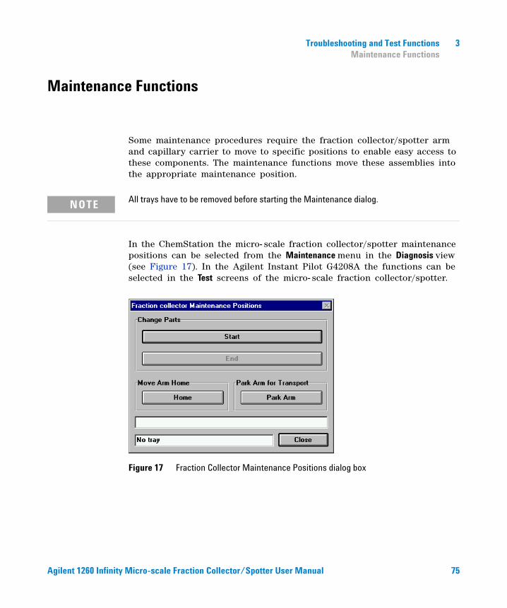
Troubleshooting and Test Functions 3Maintenance Functions
Maintenance Functions
Some maintenance procedures require the fraction collector/spotter arm and capillary carrier to move to specific positions to enable easy access to these components. The maintenance functions move these assemblies into the appropriate maintenance position.
In the ChemStation the micro- scale fraction collector/spotter maintenance positions can be selected from the Maintenance menu in the Diagnosis view (see Figure 17). In the Agilent Instant Pilot G4208A the functions can be selected in the Test screens of the micro- scale fraction collector/spotter.
NOTE All trays have to be removed before starting the Maintenance dialog.
Figure 17 Fraction Collector Maintenance Positions dialog box
Agilent 1260 Infinity Micro-scale Fraction Collector/Spotter User Manual 75
3 Troubleshooting and Test FunctionsMaintenance Functions
Change Parts.
If you click Start the transport unit will move upwards, the capillary carrier assembly will move to the front center and then turn off the rotary motor to allow free rotation of the arm. This position enables easy access...
• to change the capillary guiding assembly
• to change the micro- scale fraction collector/spotter capillary
• to change the capillary carrier assembly
• to change the micro- scale fraction collector/spotter lamp assembly
• to replace the well plate adapter with the spotting adapter or vice versa
• to align the capillary length and install the spotting tip.
After the maintenance or repair task has been finished, click End to reset the micro- scale fraction collector spotter and move the arm to the waste port.
Home Position
This maintenance function moves the arm up and to the right rear for better access and exchange of the trays.
Park Arm
This maintenance position moves the arm to the park position at the upper rear left side of the tray for transporting or shipping the micro collector/spotter.
76 Agilent 1260 Infinity Micro-scale Fraction Collector/Spotter User Manual
Troubleshooting and Test Functions 3Transport Unit Self Alignment
Transport Unit Self Alignment
The transport unit alignment is required to compensate for larger deviations in positioning the needle carrier assembly. This might be necassary after disassembling the system or when you exchange the transport unit, the capillary carrier assembly or the MTP main board.
This function is in the diagnose screen of the ChemStation or the Agilent Instant Pilot G4208A.
When is a Transport Unit Self Alignment Necessary?
The sample transport self alignment is required after disassembling the module or when you exchange:
• The transport unit.
• The capillary carrier assembly.
• The MTP main board.
WARNING The sample transport self alignment requires the 4-well-plate tray (G1364-84511 or G1364-84521). All well plates MUST be removed!
If the Transport Unit Self Alignment is started with well plates on the tray, the alignment procedure is aborted WITHOUT error message.
How to perform a Transport Unit Self Alignment?
Steps Comments
1 If the transport unit has been exchanged or if it is strongly misaligned, set the 8-bit configuration switch to the Forced Cold Start Configuration.
See Service Manual G1364-90111 for details.
2 Install the 4-well-plate tray (G1364-84511 or G1364-84521)
IMPORTANT: Remove all plates!
3 Ensure that the wellplate adapter is correctly assembled
Agilent 1260 Infinity Micro-scale Fraction Collector/Spotter User Manual 77
3 Troubleshooting and Test FunctionsTransport Unit Self Alignment
4 Select the Maintenance menu in the Diagnosis view of the Agilent ChemStation.
5 In the menu choose Fraction Collector > Transport Alignment... to start the automated procedure.
The Transport Alignment Procedure takes approximately 10-15 minutes
6 Set the 8-bit configuration switch to the default setting.
See Service Manual G1364-90111 for details.
How to perform a Transport Unit Self Alignment?
Steps Comments
78 Agilent 1260 Infinity Micro-scale Fraction Collector/Spotter User Manual
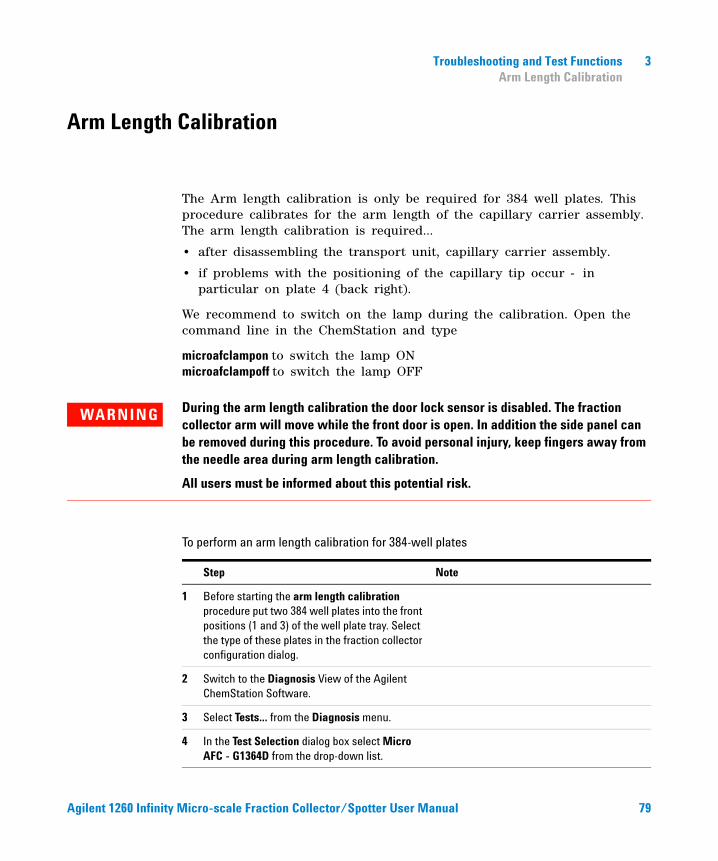
Troubleshooting and Test Functions 3Arm Length Calibration
Arm Length Calibration
The Arm length calibration is only be required for 384 well plates. This procedure calibrates for the arm length of the capillary carrier assembly. The arm length calibration is required...
• after disassembling the transport unit, capillary carrier assembly.
• if problems with the positioning of the capillary tip occur - in particular on plate 4 (back right).
We recommend to switch on the lamp during the calibration. Open the command line in the ChemStation and type
microafclampon to switch the lamp ONmicroafclampoff to switch the lamp OFF
WARNING During the arm length calibration the door lock sensor is disabled. The fraction collector arm will move while the front door is open. In addition the side panel can be removed during this procedure. To avoid personal injury, keep fingers away from the needle area during arm length calibration.
All users must be informed about this potential risk.
To perform an arm length calibration for 384-well plates
Step Note
1 Before starting the arm length calibration procedure put two 384 well plates into the front positions (1 and 3) of the well plate tray. Select the type of these plates in the fraction collector configuration dialog.
2 Switch to the Diagnosis View of the Agilent ChemStation Software.
3 Select Tests... from the Diagnosis menu.
4 In the Test Selection dialog box select Micro AFC - G1364D from the drop-down list.
Agilent 1260 Infinity Micro-scale Fraction Collector/Spotter User Manual 79
3 Troubleshooting and Test FunctionsArm Length Calibration
5 Select arm length calibration (384 well plates) and click on Start.
6 Start the arm length calibration and follow the instructions on the screen.
Click on Explain to get detailed instructions and information
7 Click the Plate 1 button in the Arm Length Calibration dialog box (Figure 18 on page 81)
The capillary carrier will move to well position A7 on plate 1
8 Use the left and right button in the dialog box (Figure 18) to adjust the capillary tip to the center of the well
9 Click the Plate 3 button in the Arm Length Calibration dialog box (Figure 18 on page 81).
The capillary carrier will move to well position A18 on plate 3
10 Use the left and right button to adjust the capillary tip to the center of the well.
11 After adjusting the capillary this way the determined values are stored by pressing the OK button.
It might take some time to store the positions on the micro-scale fraction collector/spotter.
To perform an arm length calibration for 384-well plates (continued)
Step Note
80 Agilent 1260 Infinity Micro-scale Fraction Collector/Spotter User Manual
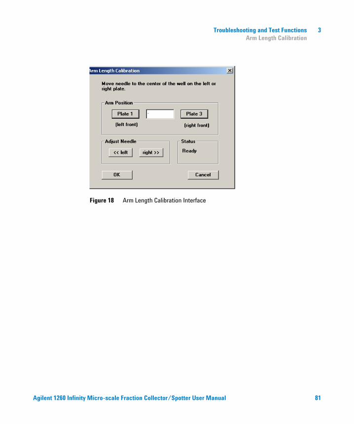
Troubleshooting and Test Functions 3Arm Length Calibration
Figure 18 Arm Length Calibration Interface
Agilent 1260 Infinity Micro-scale Fraction Collector/Spotter User Manual 81
3 Troubleshooting and Test FunctionsPosition Accuracy Calibration for 384-Well Plates
Position Accuracy Calibration for 384-Well Plates
We recommend to perform the Position Accuracy Calibration for 384- well plates...
• if the positioning is inaccurate
• after mayor repairs (e.g. exchange of transport assembly, capillary carrier or mainboard)
• after a firmware update.
• if a different type of 384- well plate is used.
We recommend switching on the lamp during the calibration. Open the command line in the ChemStation and type
microafclampon to switch the lamp ONmicroafclampoff to switch the lamp OFF
WARNING During the position accuracy calibration the door lock sensor is disabled. The fraction collector arm will move while the front door is open. In addition the side panel can be removed during this procedure. To avoid personal injury, keep fingers away from the needle area during position accuracy calibration.
All users must be informed about this potential risk.
To perform a position accuracy calibration for well plates :
Step Note
1 Switch to the Diagnosis View of the Agilent ChemStation Software
2 Select Tests... from the Diagnosis menu
3 In the Test Selection dialog box select Micro AFC - G1364D from the drop-down list.
82 Agilent 1260 Infinity Micro-scale Fraction Collector/Spotter User Manual
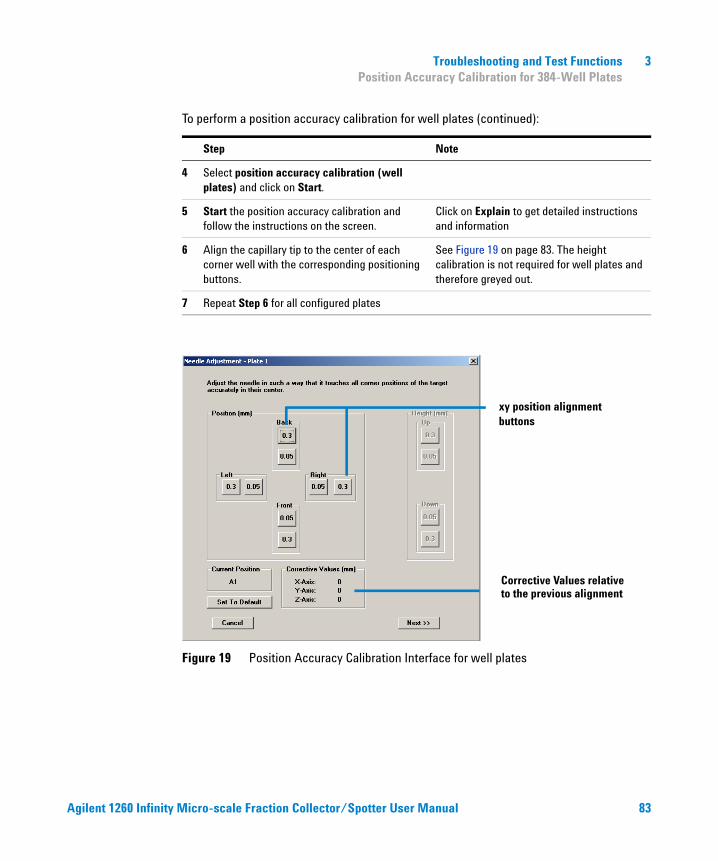
Troubleshooting and Test Functions 3Position Accuracy Calibration for 384-Well Plates
4 Select position accuracy calibration (well plates) and click on Start.
5 Start the position accuracy calibration and follow the instructions on the screen.
Click on Explain to get detailed instructions and information
6 Align the capillary tip to the center of each corner well with the corresponding positioning buttons.
See Figure 19 on page 83. The height calibration is not required for well plates andtherefore greyed out.
7 Repeat Step 6 for all configured plates
Figure 19 Position Accuracy Calibration Interface for well plates
To perform a position accuracy calibration for well plates (continued):
Step Note
xy position alignment buttons
Corrective Values relativeto the previous alignment
Agilent 1260 Infinity Micro-scale Fraction Collector/Spotter User Manual 83
3 Troubleshooting and Test FunctionsPosition Accuracy Calibration for MALDI Targets
Position Accuracy Calibration for MALDI Targets
The Position Accuracy Calibration for MALDI targets has to be performed, if
• a different type of MALDI Target is used.
• the positioning is inaccurate.
• after mayor repairs (e.g. exchange of transport assembly, capillary carrier or mainboard)
• after a firmware update.
We recommend to switch on the lamp during the calibration. Open the command line in the ChemStation and type
microafclampon to switch the lamp ONmicroafclampoff to switch the lamp OFF
WARNING During the position accuracy calibration the door lock sensor is disabled. The fraction collector arm will move while the front door is open. To avoid personal injury, keep fingers away from the needle area during position accuracy calibration.
All users must be informed about this potential risk.
CAUTION The position accuracy depends on the temperature. We recommend to perform the position accuracy alignment at the same temperature as the operation of the instrument. If a fraction collector thermostat is present, it should be switched on 30 minutes before the calibration to ensure constant temperature conditions in the module.
84 Agilent 1260 Infinity Micro-scale Fraction Collector/Spotter User Manual
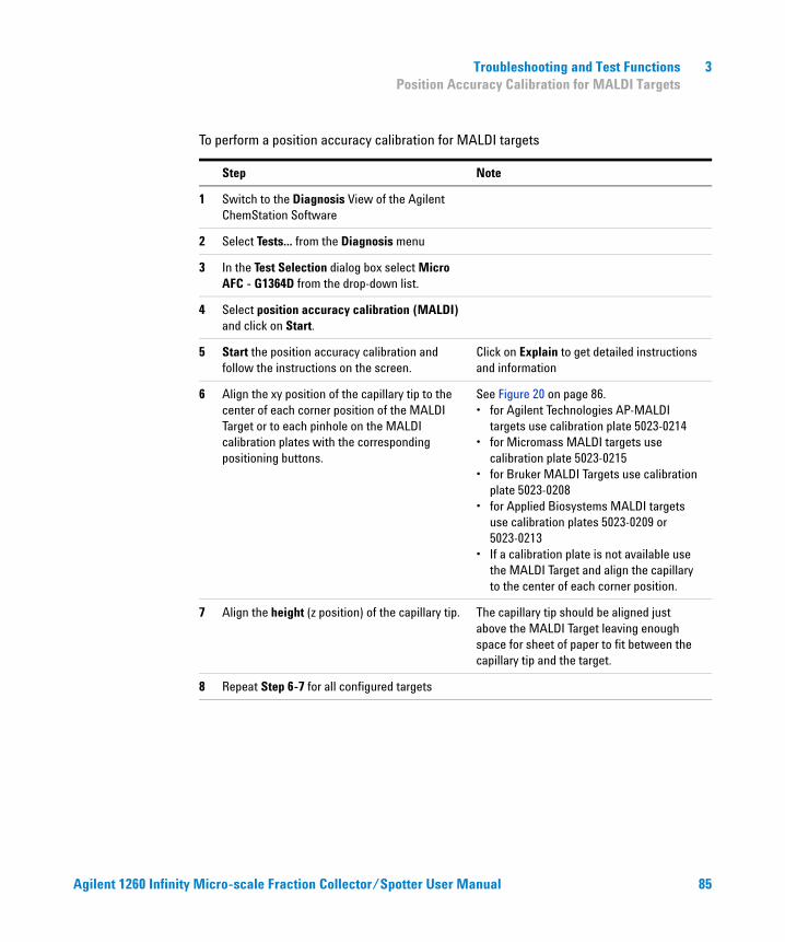
Troubleshooting and Test Functions 3Position Accuracy Calibration for MALDI Targets
To perform a position accuracy calibration for MALDI targets
Step Note
1 Switch to the Diagnosis View of the Agilent ChemStation Software
2 Select Tests... from the Diagnosis menu
3 In the Test Selection dialog box select Micro AFC - G1364D from the drop-down list.
4 Select position accuracy calibration (MALDI) and click on Start.
5 Start the position accuracy calibration and follow the instructions on the screen.
Click on Explain to get detailed instructions and information
6 Align the xy position of the capillary tip to the center of each corner position of the MALDI Target or to each pinhole on the MALDI calibration plates with the corresponding positioning buttons.
See Figure 20 on page 86.• for Agilent Technologies AP-MALDI
targets use calibration plate 5023-0214• for Micromass MALDI targets use
calibration plate 5023-0215• for Bruker MALDI Targets use calibration
plate 5023-0208• for Applied Biosystems MALDI targets
use calibration plates 5023-0209 or 5023-0213
• If a calibration plate is not available use the MALDI Target and align the capillary to the center of each corner position.
7 Align the height (z position) of the capillary tip. The capillary tip should be aligned just above the MALDI Target leaving enough space for sheet of paper to fit between the capillary tip and the target.
8 Repeat Step 6-7 for all configured targets
Agilent 1260 Infinity Micro-scale Fraction Collector/Spotter User Manual 85
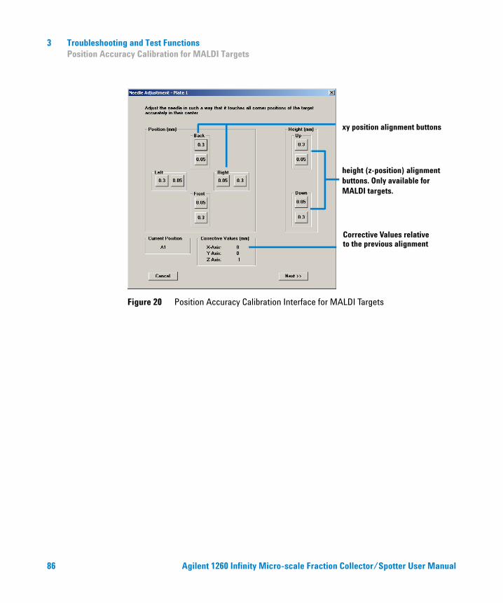
3 Troubleshooting and Test FunctionsPosition Accuracy Calibration for MALDI Targets
Figure 20 Position Accuracy Calibration Interface for MALDI Targets
xy position alignment buttons
height (z-position) alignment buttons. Only available for MALDI targets.
Corrective Values relativeto the previous alignment
86 Agilent 1260 Infinity Micro-scale Fraction Collector/Spotter User Manual
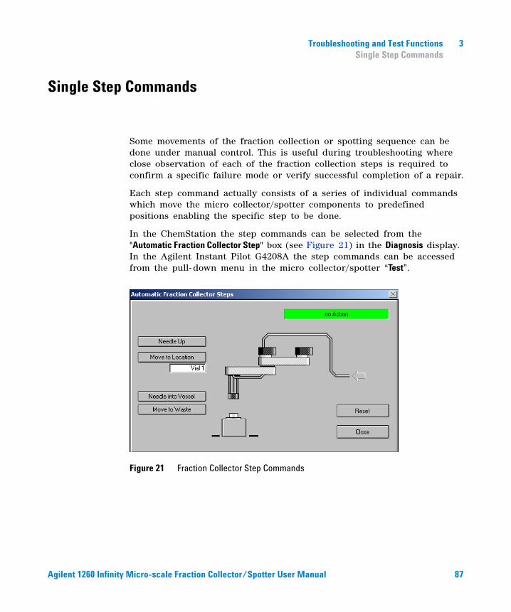
Troubleshooting and Test Functions 3Single Step Commands
Single Step Commands
Some movements of the fraction collection or spotting sequence can be done under manual control. This is useful during troubleshooting where close observation of each of the fraction collection steps is required to confirm a specific failure mode or verify successful completion of a repair.
Each step command actually consists of a series of individual commands which move the micro collector/spotter components to predefined positions enabling the specific step to be done.
In the ChemStation the step commands can be selected from the "Automatic Fraction Collector Step" box (see Figure 21) in the Diagnosis display. In the Agilent Instant Pilot G4208A the step commands can be accessed from the pull- down menu in the micro collector/spotter “Test”.
Figure 21 Fraction Collector Step Commands
Agilent 1260 Infinity Micro-scale Fraction Collector/Spotter User Manual 87
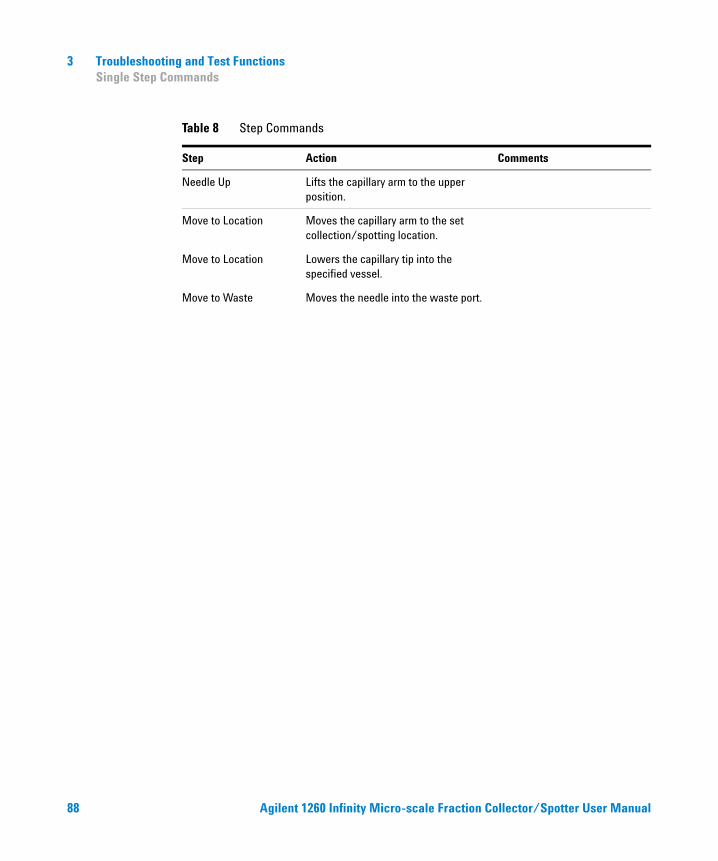
3 Troubleshooting and Test FunctionsSingle Step Commands
Table 8 Step Commands
Step Action Comments
Needle Up Lifts the capillary arm to the upper position.
Move to Location Moves the capillary arm to the set collection/spotting location.
Move to Location Lowers the capillary tip into the specified vessel.
Move to Waste Moves the needle into the waste port.
88 Agilent 1260 Infinity Micro-scale Fraction Collector/Spotter User Manual
Agilent 1260 Infinity Series Micro-scale Fraction Collector/SpotterUser Manual
4Maintenance and Simple Repairs
Introduction into Repairing the Micro-scale Fraction Collector/Spotter 90
Simple Repairs 90
Cleaning the Micro Collector/Spotter 91
Cleaning the Waste Port 92
Replacing the Micro-scale Fraction Collector/Spotter Lamp Assembly 95
Replacing Micro-scale Fraction Collector/Spotter Capillary Assembly 100
Exchanging the Capillary Guiding Assembly 103
Exchanging the Flap Septum and the Waste Tubing 105
Exchanging the Internal Tray 107
89Agilent Technologies

4 Maintenance and Simple RepairsIntroduction into Repairing the Micro-scale Fraction Collector/Spotter
Introduction into Repairing the Micro-scale Fraction Collector/Spotter
Simple Repairs
The micro collector/spotter is designed for easy repair. The most frequent repairs and maintenance tasks such as changing the capillary, the flap septum or the waste tubing can be done from the front of the instrument with the instrument in place in the system stack. These repairs are described in “Simple Repairs Procedures” on page 99.
WARNING When opening capillary or tube fittings solvents may leak out. Please observe appropriate safety procedures (for example, goggles, safety gloves and protective clothing) as described in the material handling and safety data sheet supplied by the solvent vendor, especially when toxic or hazardous solvents are used.
WARNING Regularly inspect the capillary and exchange it if they is worn out or shows visible signs of damage.
WARNING To prevent personal injury, the power cable must be removed from the instrument before removing the micro collector/spotter cover. Do not connect the power cable to the micro collector/spotter while the cover is removed.
90 Agilent 1260 Infinity Micro-scale Fraction Collector/Spotter User Manual
Maintenance and Simple Repairs 4Introduction into Repairing the Micro-scale Fraction Collector/Spotter
Cleaning the Micro Collector/Spotter
The micro collector/spotter covers should be kept clean. Cleaning should be done with a soft cloth slightly dampened with water or a solution of water and a mild detergent. Do not use an excessively damp cloth from which liquid could drip into the micro collector/spotter.
WARNING Do not let liquid drip into the micro collector/spotter. It could cause a shock hazard or damage to the micro collector/spotter.
Agilent 1260 Infinity Micro-scale Fraction Collector/Spotter User Manual 91
4 Maintenance and Simple RepairsIntroduction into Repairing the Micro-scale Fraction Collector/Spotter
Cleaning the Waste Port
Frequency The frequency depends strongly on the application.
Tools required None
Parts Required None
WARNING To avoid personal injury, keep fingers away from the capillary arm during micro collector/spotter operation.
CAUTION If solvents with high concentrations of matrix, buffer or salt are used, the capillary has to be flushed thoroughly with salt free water after analysis. Such a procedure prevents the capillary and the waste port from clogging.
NOTE For low flow rates and for MALDI spotting with online matrix delivery, we recommend to use the plug to close the waste container instead the waste tubing. The plug (G1364-26105) is included in the micro-scale fraction collector/spotter accessory kit.
92 Agilent 1260 Infinity Micro-scale Fraction Collector/Spotter User Manual
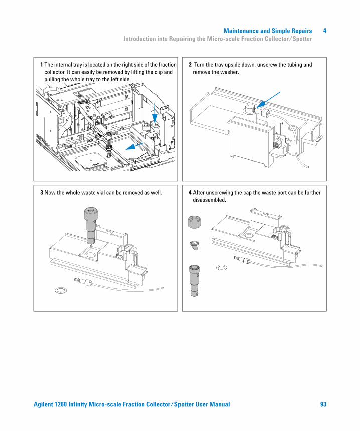
Maintenance and Simple Repairs 4Introduction into Repairing the Micro-scale Fraction Collector/Spotter
1 The internal tray is located on the right side of the fraction collector. It can easily be removed by lifting the clip and pulling the whole tray to the left side.
2 Turn the tray upside down, unscrew the tubing and remove the washer.
3 Now the whole waste vial can be removed as well. 4 After unscrewing the cap the waste port can be further disassembled.
Agilent 1260 Infinity Micro-scale Fraction Collector/Spotter User Manual 93
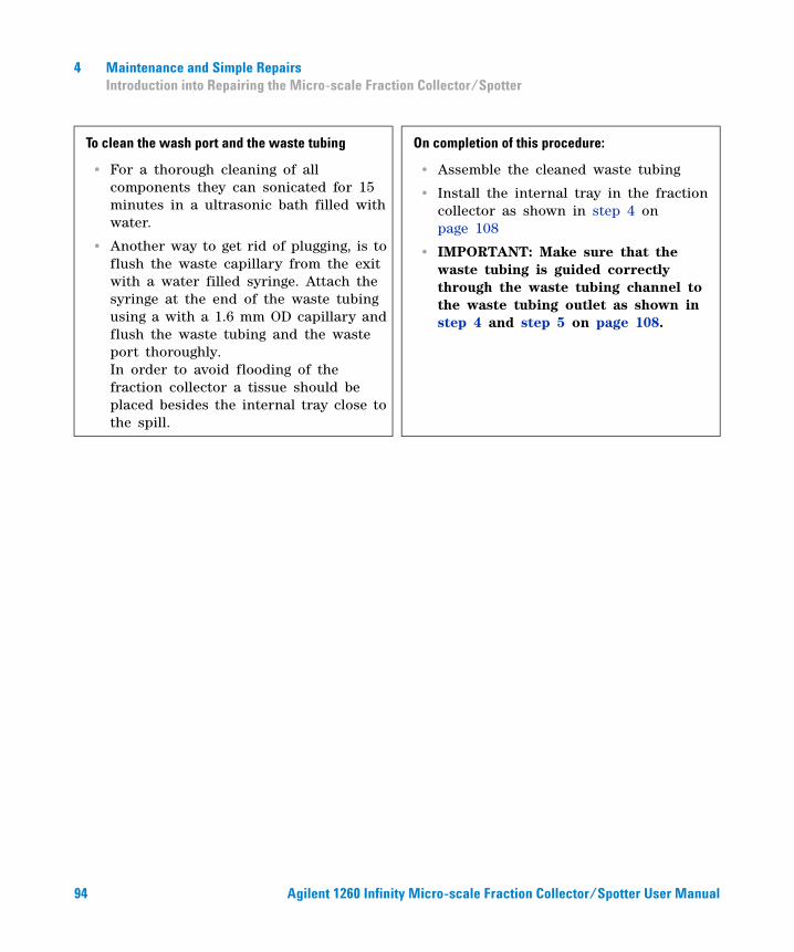
4 Maintenance and Simple RepairsIntroduction into Repairing the Micro-scale Fraction Collector/Spotter
To clean the wash port and the waste tubing
• For a thorough cleaning of all components they can sonicated for 15 minutes in a ultrasonic bath filled with water.
• Another way to get rid of plugging, is to flush the waste capillary from the exit with a water filled syringe. Attach the syringe at the end of the waste tubing using a with a 1.6 mm OD capillary and flush the waste tubing and the waste port thoroughly.In order to avoid flooding of the fraction collector a tissue should be placed besides the internal tray close to the spill.
On completion of this procedure:
• Assemble the cleaned waste tubing
• Install the internal tray in the fraction collector as shown in step 4 on page 108
• IMPORTANT: Make sure that the waste tubing is guided correctly through the waste tubing channel to the waste tubing outlet as shown in step 4 and step 5 on page 108.
94 Agilent 1260 Infinity Micro-scale Fraction Collector/Spotter User Manual
Maintenance and Simple Repairs 4Replacing the Micro-scale Fraction Collector/Spotter Lamp Assembly
Replacing the Micro-scale Fraction Collector/Spotter Lamp Assembly
Frequency When lamp is defective or not required in the micro-scale fraction collector/spotter
Tools required None
Parts Required Micro-scale fraction collector/spotter lamp assembly G1364-60014
WARNING To avoid personal injury, keep fingers away from the capillary arm during micro collector/spotter operation.
WARNING Explicitly follow the described installation procedures to maximize the lifetime of the fraction collector capillary and to avoid potential spills or fraction losses. Regularly inspect the capillary and exchange it if it is worn out or shows visible signs of damage.
Agilent 1260 Infinity Micro-scale Fraction Collector/Spotter User Manual 95
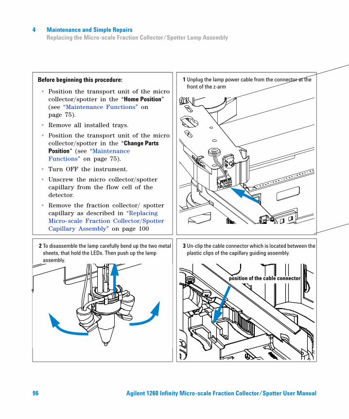
4 Maintenance and Simple RepairsReplacing the Micro-scale Fraction Collector/Spotter Lamp Assembly
Before beginning this procedure:
• Position the transport unit of the micro collector/spotter in the “Home Position” (see “Maintenance Functions” on page 75).
• Remove all installed trays.
• Position the transport unit of the micro collector/spotter in the “Change Parts Position” (see “Maintenance Functions” on page 75).
• Turn OFF the instrument.
• Unscrew the micro collector/spotter capillary from the flow cell of the detector.
• Remove the fraction collector/ spotter capillary as described in “Replacing Micro- scale Fraction Collector/Spotter Capillary Assembly” on page 100
1 Unplug the lamp power cable from the connector at the front of the z-arm
2 To disassemble the lamp carefully bend up the two metal sheets, that hold the LEDs. Then push up the lamp assembly.
3 Un-clip the cable connector which is located between the plastic clips of the capillary guiding assembly.
position of the cable connector
96 Agilent 1260 Infinity Micro-scale Fraction Collector/Spotter User Manual
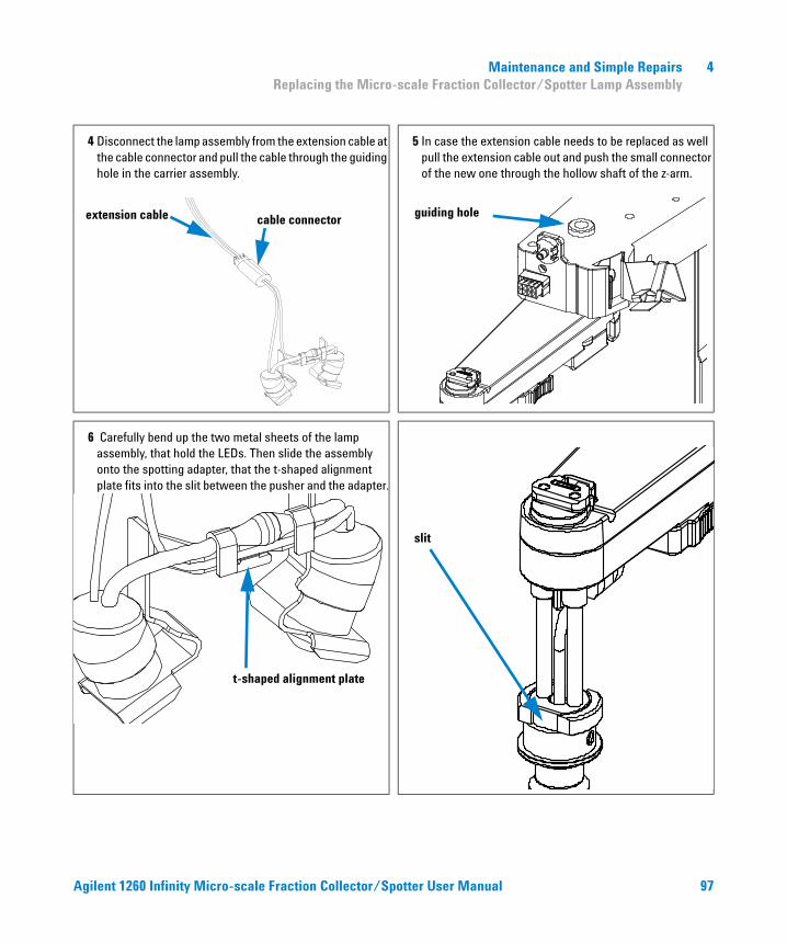
Maintenance and Simple Repairs 4Replacing the Micro-scale Fraction Collector/Spotter Lamp Assembly
4 Disconnect the lamp assembly from the extension cable at the cable connector and pull the cable through the guiding hole in the carrier assembly.
5 In case the extension cable needs to be replaced as well pull the extension cable out and push the small connector of the new one through the hollow shaft of the z-arm.
6 Carefully bend up the two metal sheets of the lamp assembly, that hold the LEDs. Then slide the assembly onto the spotting adapter, that the t-shaped alignment plate fits into the slit between the pusher and the adapter.
cable connectorextension cable guiding hole
t-shaped alignment plate
slit
Agilent 1260 Infinity Micro-scale Fraction Collector/Spotter User Manual 97
4 Maintenance and Simple RepairsReplacing the Micro-scale Fraction Collector/Spotter Lamp Assembly
• Connect the lamp assembly to the extension cable.
• Push the cable connector in- between the yellow plastic clip as described in step 3 of this procedure.
• Plug the lamp power cable into the connector at the front of the z- arm.
• Install the fraction collector/ spotter capillary as described in “Replacing Micro- scale Fraction Collector/Spotter Capillary Assembly” on page 100
• To activate the lamp switch open the command line in the ChemStation and typemicroafclamponto switch the lamp ONmicroafclampoffto switch the lamp OFF
98 Agilent 1260 Infinity Micro-scale Fraction Collector/Spotter User Manual
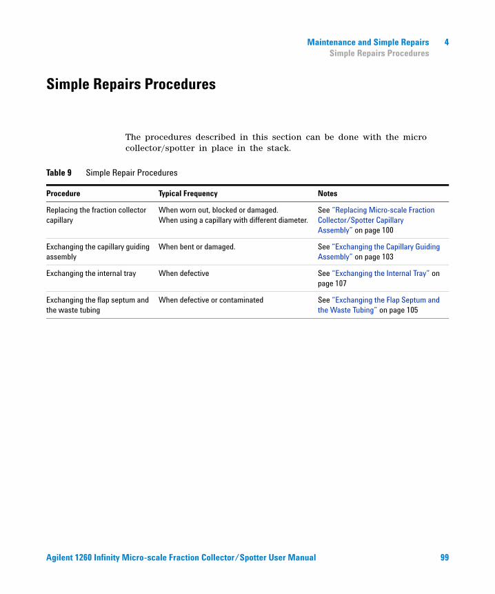
Maintenance and Simple Repairs 4Simple Repairs Procedures
Simple Repairs Procedures
The procedures described in this section can be done with the micro collector/spotter in place in the stack.
Table 9 Simple Repair Procedures
Procedure Typical Frequency Notes
Replacing the fraction collector capillary
When worn out, blocked or damaged.When using a capillary with different diameter.
See “Replacing Micro-scale Fraction Collector/Spotter Capillary Assembly” on page 100
Exchanging the capillary guiding assembly
When bent or damaged. See “Exchanging the Capillary Guiding Assembly” on page 103
Exchanging the internal tray When defective See “Exchanging the Internal Tray” on page 107
Exchanging the flap septum and the waste tubing
When defective or contaminated See “Exchanging the Flap Septum and the Waste Tubing” on page 105
Agilent 1260 Infinity Micro-scale Fraction Collector/Spotter User Manual 99
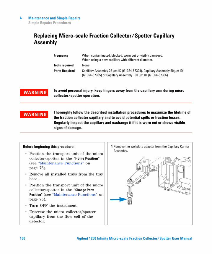
4 Maintenance and Simple RepairsSimple Repairs Procedures
Replacing Micro-scale Fraction Collector/Spotter Capillary Assembly
Frequency When contaminated, blocked, worn out or visibly damaged.When using a new capillary with different diameter.
Tools required None
Parts Required Capillary Assembly 25 μm ID (G1364-87304), Capillary Assembly 50 μm ID (G1364-87305) or Capillary Assembly 100 μm ID (G1364-87306)
WARNING To avoid personal injury, keep fingers away from the capillary arm during micro collector/spotter operation.
WARNING Thoroughly follow the described installation procedures to maximize the lifetime of the fraction collector capillary and to avoid potential spills or fraction losses. Regularly inspect the capillary and exchange it if it is worn out or shows visible signs of damage.
Before beginning this procedure:
• Position the transport unit of the micro collector/spotter in the “Home Position” (see “Maintenance Functions” on page 75).
• Remove all installed trays from the tray base.
• Position the transport unit of the micro collector/spotter in the “Change Parts Position” (see “Maintenance Functions” on page 75).
• Turn OFF the instrument.
• Unscrew the micro collector/spotter capillary from the flow cell of the detector.
1 Remove the wellplate adapter from the Capillary Carrier Assembly.
100 Agilent 1260 Infinity Micro-scale Fraction Collector/Spotter User Manual
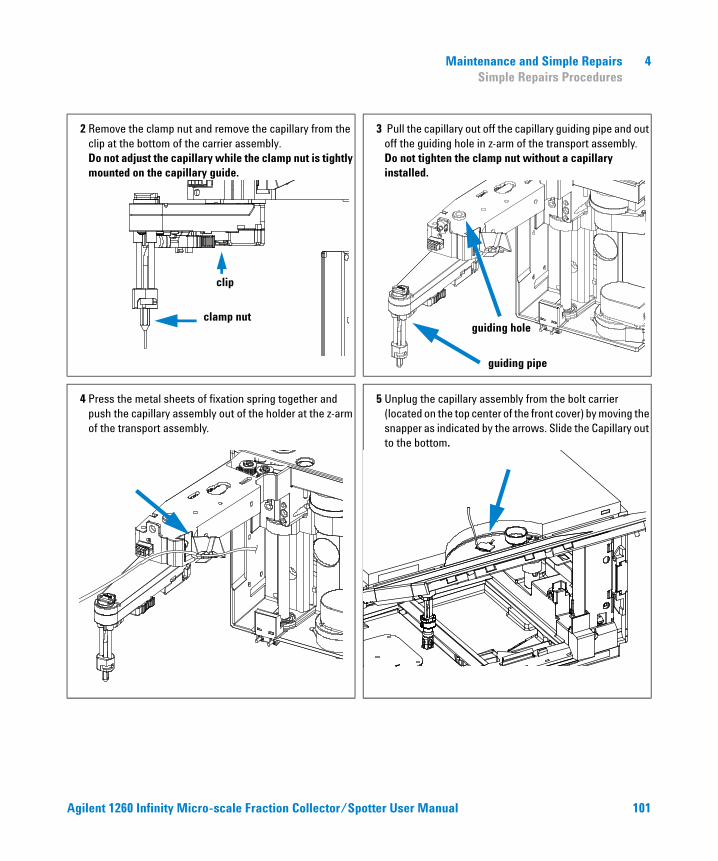
Maintenance and Simple Repairs 4Simple Repairs Procedures
2 Remove the clamp nut and remove the capillary from the clip at the bottom of the carrier assembly.Do not adjust the capillary while the clamp nut is tightly mounted on the capillary guide.
3 Pull the capillary out off the capillary guiding pipe and out off the guiding hole in z-arm of the transport assembly.Do not tighten the clamp nut without a capillary installed.
4 Press the metal sheets of fixation spring together and push the capillary assembly out of the holder at the z-arm of the transport assembly.
5 Unplug the capillary assembly from the bolt carrier (located on the top center of the front cover) by moving the snapper as indicated by the arrows. Slide the Capillary out to the bottom.
clamp nut
clip
guiding pipe
guiding hole
Agilent 1260 Infinity Micro-scale Fraction Collector/Spotter User Manual 101
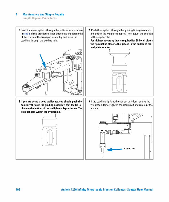
4 Maintenance and Simple RepairsSimple Repairs Procedures
6 Push the new capillary through the bolt carrier as shown in step 5 of this procedure. Then attach the fixation spring at the z-arm of the transport assembly and push the capillary through the guiding hole.
7 Push the capillary through the guiding fitting assembly and attach the wellplate adapter. Then adjust the position of the capillary tip.For highest accuracy that is required for 384 well plates the tip must be close to the groove in the middle of the wellplate adapter.
8 If you are using a deep well plate, you should push the capillary through the guiding assembly, that the tip is close to the bottom of the wellplate adapter frame. The tip must stay within the oval frame.
9 If the capillary tip is at the correct position, remove the wellplate adapter, tighten the clamp nut and remount the adapter.
clamp nut
102 Agilent 1260 Infinity Micro-scale Fraction Collector/Spotter User Manual
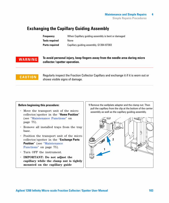
Maintenance and Simple Repairs 4Simple Repairs Procedures
Exchanging the Capillary Guiding Assembly
Frequency When Capillary guiding assembly is bent or damaged
Tools required None
Parts required Capillary guiding assembly, G1364-87303
WARNING To avoid personal injury, keep fingers away from the needle area during micro collector/spotter operation.
CAUTION Regularly inspect the Fraction Collector Capillary and exchange it if it is worn out or shows visible signs of damage.
Before beginning this procedure:
• Move the transport unit of the micro collector/spotter in the “Home Position” (see “Maintenance Functions” on page 75).
• Remove all installed trays from the tray base.
• Position the transport unit of the micro collector/spotter in the “Exchange Parts Position” (see “Maintenance Functions” on page 75).
• Turn OFF the instrument.
• IMPORTANT: Do not adjust the capillary while the clamp nut is tightly mounted on the capillary guide
1 Remove the wellplate adapter and the clamp nut. Then pull the capillary from the clip at the bottom of the carrier assembly as well as the capillary guiding assembly.
1
2
Agilent 1260 Infinity Micro-scale Fraction Collector/Spotter User Manual 103
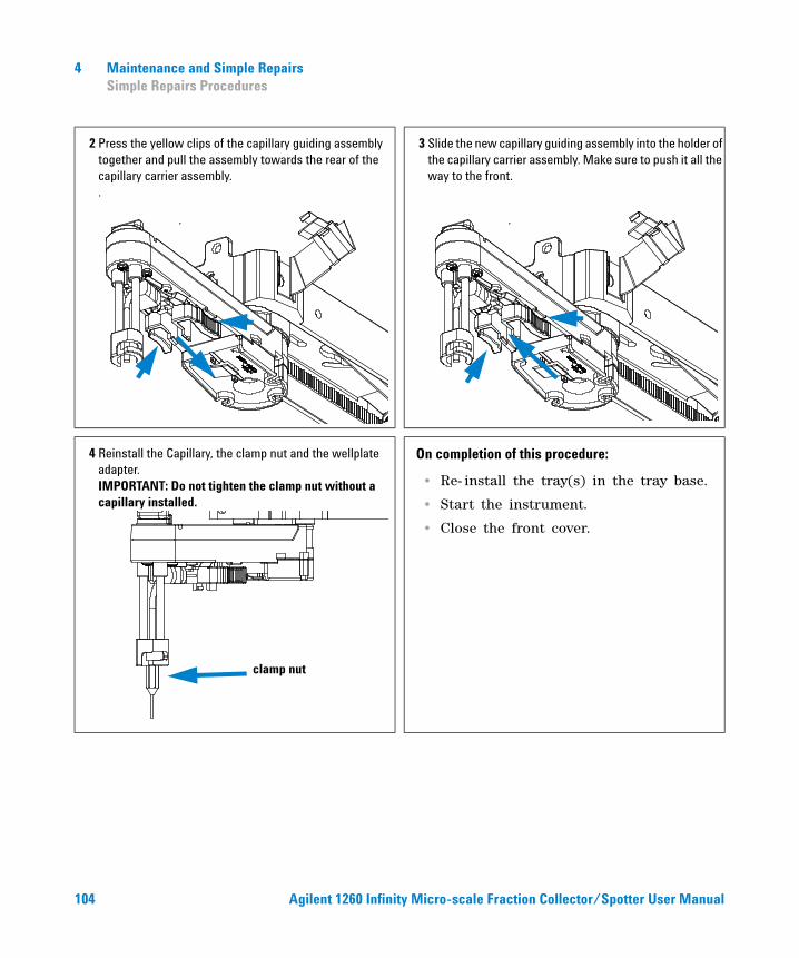
4 Maintenance and Simple RepairsSimple Repairs Procedures
2 Press the yellow clips of the capillary guiding assembly together and pull the assembly towards the rear of the capillary carrier assembly..
3 Slide the new capillary guiding assembly into the holder of the capillary carrier assembly. Make sure to push it all the way to the front.
4 Reinstall the Capillary, the clamp nut and the wellplate adapter.IMPORTANT: Do not tighten the clamp nut without a capillary installed.
On completion of this procedure:
• Re- install the tray(s) in the tray base.
• Start the instrument.
• Close the front cover.
clamp nut
104 Agilent 1260 Infinity Micro-scale Fraction Collector/Spotter User Manual
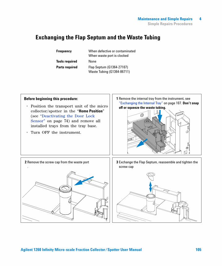
Maintenance and Simple Repairs 4Simple Repairs Procedures
Exchanging the Flap Septum and the Waste Tubing
Frequency When defective or contaminatedWhen waste port is clocked
Tools required None
Parts required Flap Septum (G1364-27107)Waste Tubing (G1364-86711)
Before beginning this procedure:
• Position the transport unit of the micro collector/spotter in the “Home Position” (see “Deactivating the Door Lock Sensor” on page 74) and remove all installed trays from the tray base.
• Turn OFF the instrument.
1 Remove the internal tray from the instrument, see “Exchanging the Internal Tray” on page 107. Don’t snap off or squeeze the waste tubing.
2 Remove the screw cap from the waste port.
3 Exchange the Flap Septum, reassemble and tighten the screw cap
Agilent 1260 Infinity Micro-scale Fraction Collector/Spotter User Manual 105
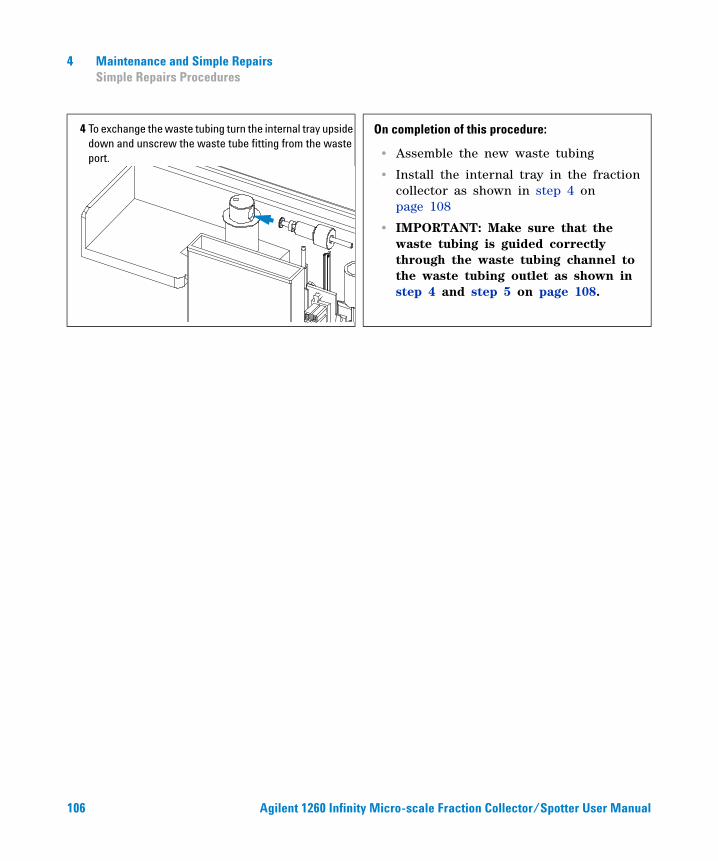
4 Maintenance and Simple RepairsSimple Repairs Procedures
4 To exchange the waste tubing turn the internal tray upside down and unscrew the waste tube fitting from the waste port.
On completion of this procedure:
• Assemble the new waste tubing
• Install the internal tray in the fraction collector as shown in step 4 on page 108
• IMPORTANT: Make sure that the waste tubing is guided correctly through the waste tubing channel to the waste tubing outlet as shown in step 4 and step 5 on page 108.
106 Agilent 1260 Infinity Micro-scale Fraction Collector/Spotter User Manual
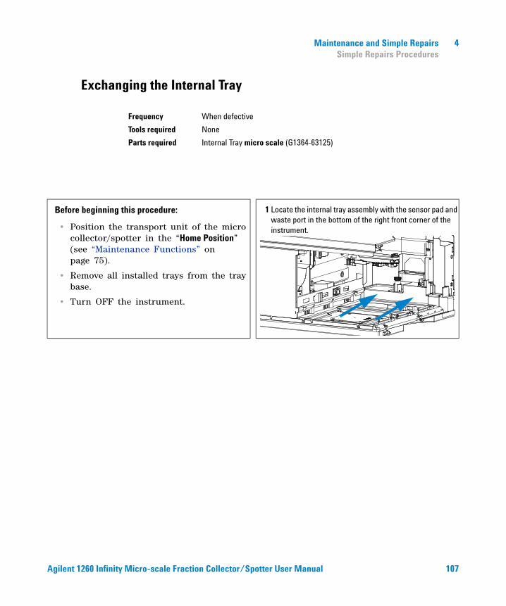
Maintenance and Simple Repairs 4Simple Repairs Procedures
Exchanging the Internal Tray
Frequency When defective
Tools required None
Parts required Internal Tray micro scale (G1364-63125)
Before beginning this procedure:
• Position the transport unit of the micro collector/spotter in the “Home Position” (see “Maintenance Functions” on page 75).
• Remove all installed trays from the tray base.
• Turn OFF the instrument.
1 Locate the internal tray assembly with the sensor pad and waste port in the bottom of the right front corner of the instrument.
Agilent 1260 Infinity Micro-scale Fraction Collector/Spotter User Manual 107
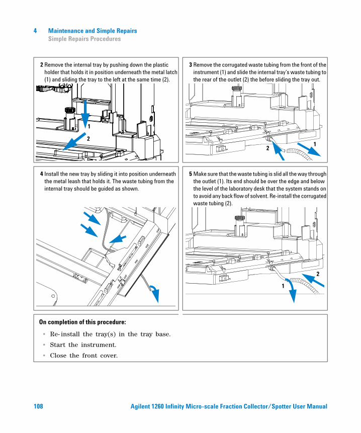
4 Maintenance and Simple RepairsSimple Repairs Procedures
2 Remove the internal tray by pushing down the plastic holder that holds it in position underneath the metal latch (1) and sliding the tray to the left at the same time (2).
3 Remove the corrugated waste tubing from the front of the instrument (1) and slide the internal tray’s waste tubing to the rear of the outlet (2) the before sliding the tray out.
4 Install the new tray by sliding it into position underneath the metal leash that holds it. The waste tubing from the internal tray should be guided as shown.
5 Make sure that the waste tubing is slid all the way through the outlet (1). Its end should be over the edge and below the level of the laboratory desk that the system stands on to avoid any back flow of solvent. Re-install the corrugated waste tubing (2).
On completion of this procedure:
• Re- install the tray(s) in the tray base.
• Start the instrument.
• Close the front cover.
2
1 CellFrame
12
CellFrame
2
1
108 Agilent 1260 Infinity Micro-scale Fraction Collector/Spotter User Manual
Agilent 1260 Infinity Series Micro-scale Fraction Collector/SpotterUser Manual
5Parts and Materials
Supported Trays for the Micro-scale Fraction Collector/Spotter 110
List of Recommended Plates 112
MALDI Spotting Accessories 113
Supported MALDI Targets 115
Transport Unit Assembly 117
Internal Tray Assembly 118
Micro-scale Fraction Collector/Spotter Accessory Kit 119
109Agilent Technologies
5 Parts and MaterialsSupported Trays for the Micro-scale Fraction Collector/Spotter
Supported Trays for the Micro-scale Fraction Collector/Spotter
Table 10 Trays for the Micro-scale Fraction Collector/Spotter
Item Description Part Number
1 Full tray for 4 well plates G1364-84521
2 Full tray for 4 MALDI plate carriers, adjustable G1364-84511
3 Std. tray for 2 well plates + 10 2ml vials G1367-60011
4 Adapter air channel (installed underneath plug channel, if the fraction collector is used with the thermostat)
G1329-43200
5 Plug channel G1364-47200
NOTE Only one type of well-plate can be used at a time.
110 Agilent 1260 Infinity Micro-scale Fraction Collector/Spotter User Manual
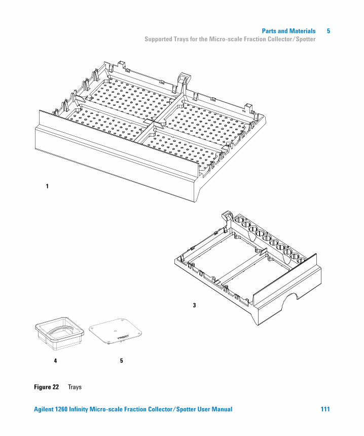
Parts and Materials 5Supported Trays for the Micro-scale Fraction Collector/Spotter
Figure 22 Trays
4 5
3
1
Agilent 1260 Infinity Micro-scale Fraction Collector/Spotter User Manual 111
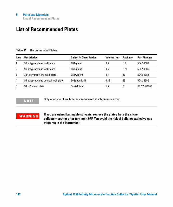
5 Parts and MaterialsList of Recommended Plates
List of Recommended Plates
Table 11 Recommended Plates
Item Description Select in ChemStation Volume (ml) Package Part Number
1 96 polypropylene well-plate 96Agilent 0.5 10 5042-1386
2 96 polypropylene well-plate 96Agilent 0.5 120 5042-1385
3 384 polypropylene well-plate 384Agilent 0.1 30 5042-1388
4 96 polypropylene conical-well plate 96EppendorfC 0.18 25 5042-8502
5 54 x 2ml vial plate 54VialPlate 1.5 6 G2255-68700
NOTE Only one type of well-plates can be used at a time in one tray.
WARNING If you are using flammable solvents, remove the plates from the micro collector/spotter after turning it 0FF. You avoid the risk of building explosive gas mixtures in the instrument.
112 Agilent 1260 Infinity Micro-scale Fraction Collector/Spotter User Manual
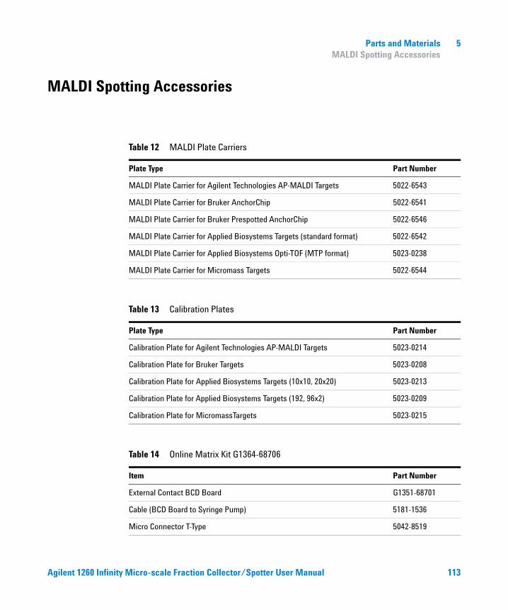
Parts and Materials 5MALDI Spotting Accessories
MALDI Spotting Accessories
Table 12 MALDI Plate Carriers
Plate Type Part Number
MALDI Plate Carrier for Agilent Technologies AP-MALDI Targets 5022-6543
MALDI Plate Carrier for Bruker AnchorChip 5022-6541
MALDI Plate Carrier for Bruker Prespotted AnchorChip 5022-6546
MALDI Plate Carrier for Applied Biosystems Targets (standard format) 5022-6542
MALDI Plate Carrier for Applied Biosystems Opti-TOF (MTP format) 5023-0238
MALDI Plate Carrier for Micromass Targets 5022-6544
Table 13 Calibration Plates
Plate Type Part Number
Calibration Plate for Agilent Technologies AP-MALDI Targets 5023-0214
Calibration Plate for Bruker Targets 5023-0208
Calibration Plate for Applied Biosystems Targets (10x10, 20x20) 5023-0213
Calibration Plate for Applied Biosystems Targets (192, 96x2) 5023-0209
Calibration Plate for MicromassTargets 5023-0215
Table 14 Online Matrix Kit G1364-68706
Item Part Number
External Contact BCD Board G1351-68701
Cable (BCD Board to Syringe Pump) 5181-1536
Micro Connector T-Type 5042-8519
Agilent 1260 Infinity Micro-scale Fraction Collector/Spotter User Manual 113
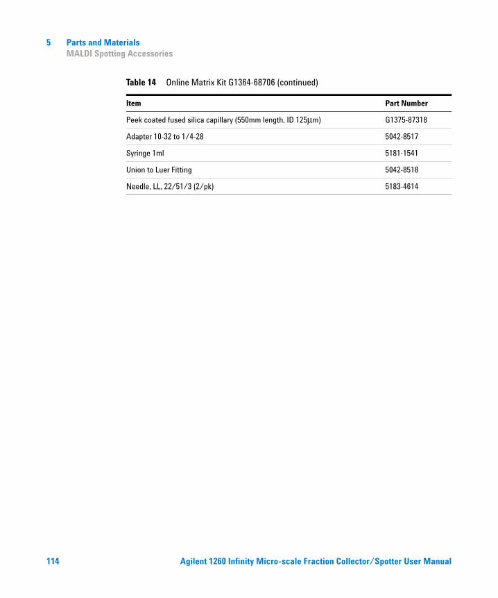
5 Parts and MaterialsMALDI Spotting Accessories
Peek coated fused silica capillary (550mm length, ID 125μm) G1375-87318
Adapter 10-32 to 1/4-28 5042-8517
Syringe 1ml 5181-1541
Union to Luer Fitting 5042-8518
Needle, LL, 22/51/3 (2/pk) 5183-4614
Table 14 Online Matrix Kit G1364-68706 (continued)
Item Part Number
114 Agilent 1260 Infinity Micro-scale Fraction Collector/Spotter User Manual
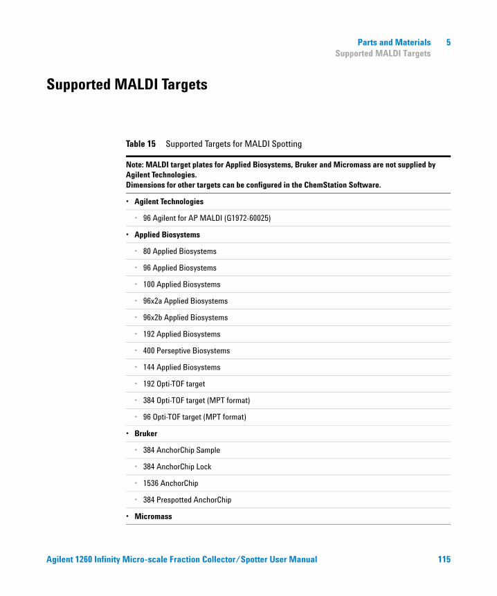
Parts and Materials 5Supported MALDI Targets
Supported MALDI Targets
Table 15 Supported Targets for MALDI Spotting
Note: MALDI target plates for Applied Biosystems, Bruker and Micromass are not supplied by Agilent Technologies.Dimensions for other targets can be configured in the ChemStation Software.
• Agilent Technologies
• 96 Agilent for AP MALDI (G1972-60025)
• Applied Biosystems
• 80 Applied Biosystems
• 96 Applied Biosystems
• 100 Applied Biosystems
• 96x2a Applied Biosystems
• 96x2b Applied Biosystems
• 192 Applied Biosystems
• 400 Perseptive Biosystems
• 144 Applied Biosystems
• 192 Opti-TOF target
• 384 Opti-TOF target (MPT format)
• 96 Opti-TOF target (MPT format)
• Bruker
• 384 AnchorChip Sample
• 384 AnchorChip Lock
• 1536 AnchorChip
• 384 Prespotted AnchorChip
• Micromass
Agilent 1260 Infinity Micro-scale Fraction Collector/Spotter User Manual 115
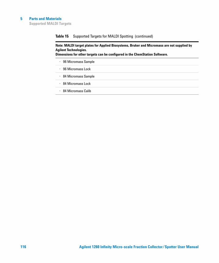
5 Parts and MaterialsSupported MALDI Targets
• 96 Micromass Sample
• 96 Micromass Lock
• 84 Micromass Sample
• 84 Micromass Lock
• 84 Micromass Calib
Table 15 Supported Targets for MALDI Spotting (continued)
Note: MALDI target plates for Applied Biosystems, Bruker and Micromass are not supplied by Agilent Technologies.Dimensions for other targets can be configured in the ChemStation Software.
116 Agilent 1260 Infinity Micro-scale Fraction Collector/Spotter User Manual
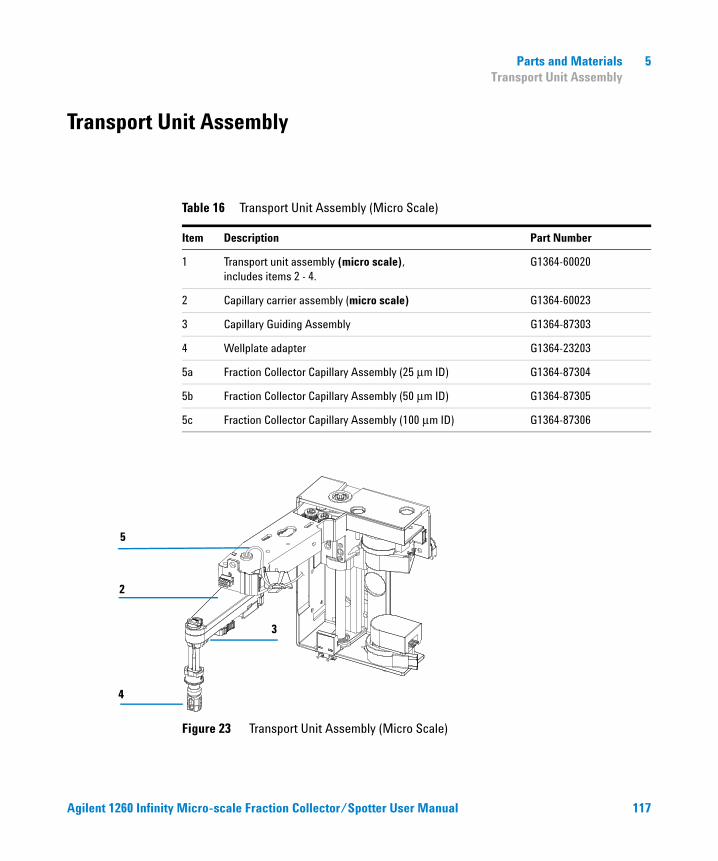
Parts and Materials 5Transport Unit Assembly
Transport Unit Assembly
Table 16 Transport Unit Assembly (Micro Scale)
Item Description Part Number
1 Transport unit assembly (micro scale), includes items 2 - 4.
G1364-60020
2 Capillary carrier assembly (micro scale) G1364-60023
3 Capillary Guiding Assembly G1364-87303
4 Wellplate adapter G1364-23203
5a Fraction Collector Capillary Assembly (25 μm ID) G1364-87304
5b Fraction Collector Capillary Assembly (50 μm ID) G1364-87305
5c Fraction Collector Capillary Assembly (100 μm ID) G1364-87306
Figure 23 Transport Unit Assembly (Micro Scale)
3
2
4
5
Agilent 1260 Infinity Micro-scale Fraction Collector/Spotter User Manual 117
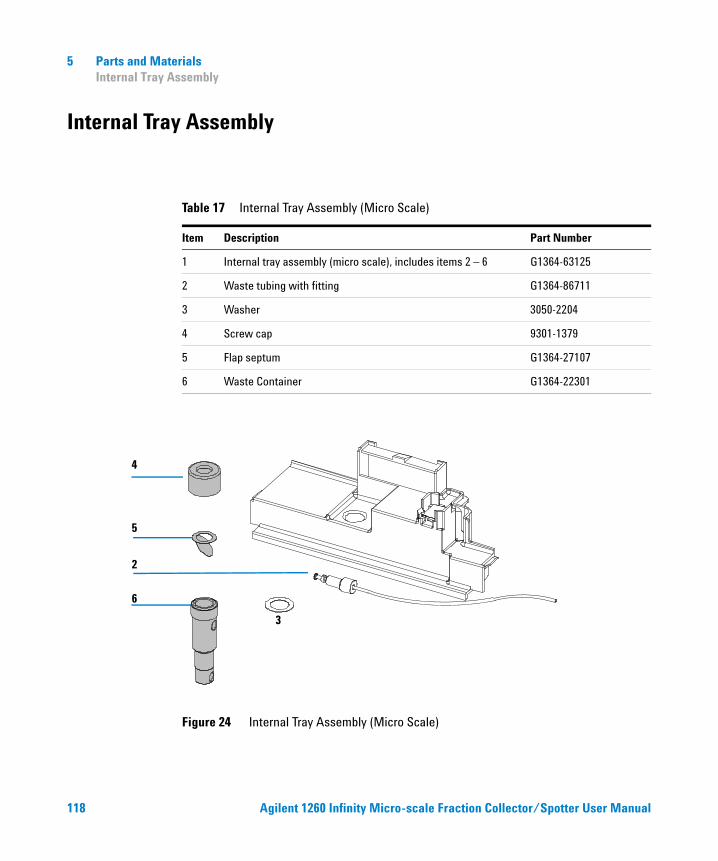
5 Parts and MaterialsInternal Tray Assembly
Internal Tray Assembly
Table 17 Internal Tray Assembly (Micro Scale)
Item Description Part Number
1 Internal tray assembly (micro scale), includes items 2 – 6 G1364-63125
2 Waste tubing with fitting G1364-86711
3 Washer 3050-2204
4 Screw cap 9301-1379
5 Flap septum G1364-27107
6 Waste Container G1364-22301
Figure 24 Internal Tray Assembly (Micro Scale)
4
5
6
2
3
118 Agilent 1260 Infinity Micro-scale Fraction Collector/Spotter User Manual
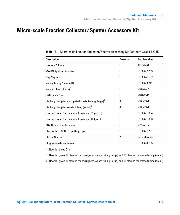
Parts and Materials 5Micro-scale Fraction Collector/Spotter Accessory Kit
Micro-scale Fraction Collector/Spotter Accessory Kit
Table 18 Micro-scale Fraction Collector/Spotter Accessory Kit Contents G1364-68715
Description Quantity Part Number
Hex key 2.0 mm 1 8710-2476
MALDI Spotting Adapter 1 G1364-83205
Flap Septum 1 G1364-27107
Waste Tubing 1.4 mm ID 1 G1364-86711
Waste tubing (1.2 m)*
* Reorder gives 5 m
1 5062-2463
CAN cable, 1 m 1 5181-1519
Sticking clamp for corrugated waste tubing (large)†
† Reorder gives 10 clamps for corrugated waste tubing (large) and 10 clamps for waste tubing (small)
3 5065-9976
Sticking clamp for waste tubing (small)‡
‡ Reorder gives 10 clamps for corrugated waste tubing (large) and 10 clamps for waste tubing (small)
3 5065-9976
Fraction Collector Capillary Assembly (25 μm ID) 1 G1364-87304
Fraction Collector Capillary Assembly (100 μm ID) 1 G1364-87306
ZDV Union, stainless steel 1 5022-2184
Strip with 10 MALDI Spotting Tips 1 G1364-81701
Plastic Spacers 20 not orderable
Plug for waste container 1 G1364-26105
Agilent 1260 Infinity Micro-scale Fraction Collector/Spotter User Manual 119
5 Parts and MaterialsMicro-scale Fraction Collector/Spotter Accessory Kit
120 Agilent 1260 Infinity Micro-scale Fraction Collector/Spotter User Manual
Agilent 1260 Infinity Series Micro-scale Fraction Collector/SpotterUser Manual
6Specifications
Performance Specifications for the Micro Collector/Spotter 122
121Agilent Technologies
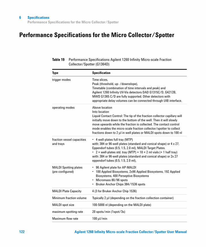
6 SpecificationsPerformance Specifications for the Micro Collector/Spotter
Performance Specifications for the Micro Collector/Spotter
Table 19 Performance Specifications Agilent 1260 Infinity Micro-scale Fraction Collector/Spotter (G1364D)
Type Specification
trigger modes Time slices, Peak (threshold, up- /downslope),Timetable (combination of time intervals and peak) andAgilent 1260 Infinity UV-Vis detectors DAD G1315C/D, G4212B, MWD G1365 C/D are fully supported. Other detectors with appropriate delay volumes can be connected through UIB interface.
operating modes Above locationInto locationLiquid Contact Control: The tip of the fraction collector capillary will initially move down to the bottom of the well. Then it will slowly move upwards while the fraction is collected. The contact control mode enables the micro-scale fraction collector/spotter to collect fractions down to 2 μl in well plates or MALDI spots down to 100 nl
fraction vessel capacities and trays
• 4 well-plates full tray (MTP)with: 384 or 96-well plates (standard and conical shape) or 4 x 27, Eppendorf tubes (0.5, 1.5, 2.0 ml), MALDI Target Plates.• 2 × well-plates std. tray (MTP) + 10 × 2 ml vials (+ 1 half tray)with: 384 or 96-well plates (standard and conical shape) or 2x 27 eppendorf tubes (0.5, 1.5, 2.0 ml),
MALDI Spotting plates(pre-configured)
• 96 Agilent plate for AP-MALDI• 100 Applied Biosystems, 2x96 Applied Biosystems, 192 Applied
Biosystems, 400 Perseptive Biosystems• Micromass 80/96 spots• Bruker Anchor Chips 384/1536 spots
MALDI Plate Capacity 4 (3 for Bruker Anchor Chip 1536)
Minimum fraction volume Typically 2 μl (depending on the fraction collection container)
MALDI spot size 100-5000 nl (depending on the MALDI plate)
maximum spotting rate 20 spots/min (1spot/3s)
Maximum flow rate 100 μl/min
122 Agilent 1260 Infinity Micro-scale Fraction Collector/Spotter User Manual
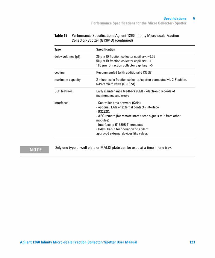
Specifications 6Performance Specifications for the Micro Collector/Spotter
delay volumes [μl] 25 μm ID fraction collector capillary: ~0.2550 μm ID fraction collector capillary: ~1100 μm ID fraction collector capillary: ~5
cooling Recommended (with additional G1330B)
maximum capacity 2 micro-scale fraction collector/spotter connected via 2-Position, 6-Port micro valve (G1162A)
GLP features Early maintenance feedback (EMF), electronic records of maintenance and errors
interfaces - Controller-area network (CAN). - optional; LAN or external contacts interface- RS232C,- APG-remote (for remote start / stop signals to / from other modules)- Interface to G1330B Thermostat- CAN-DC-out for operation of Agilentapproved external devices like valves
Table 19 Performance Specifications Agilent 1260 Infinity Micro-scale Fraction Collector/Spotter (G1364D) (continued)
Type Specification
NOTE Only one type of well plate or MALDI plate can be used at a time in one tray.
Agilent 1260 Infinity Micro-scale Fraction Collector/Spotter User Manual 123
6 SpecificationsPerformance Specifications for the Micro Collector/Spotter
124 Agilent 1260 Infinity Micro-scale Fraction Collector/Spotter User Manual
Agilent 1260 Infinity Series Micro-scale Fraction Collector/SpotterUser Manual
ASafety Information
Safety Information 126
Lithium Batteries Information 129
Radio Interference 130
Sound Emission 131
Solvent Information 132
Agilent Technologies on Internet 133
125Agilent Technologies
A Safety InformationSafety Information
Safety Information
The following general safety precautions must be observed during all phases of operation, service, and repair of this instrument. Failure to comply with these precautions or with specific warnings elsewhere in this manual violates safety standards of design, manufacture, and intended use of the instrument. Agilent Technologies assumes no liability for the customer’s failure to comply with these requirements.
General
This is a Safety Class I instrument (provided with terminal for protective earthing) and has been manufactured and tested according to international safety standards.
WARNING If you are using flammable solvents, remove the well-plates from the tray when you turn off the sampler. You avoid the risk of building explosive gas mixtures in the tray compartment.
WARNING After a leak in the sampler, make sure the leak plane is cleaned and dry.
126 Agilent 1260 Infinity Micro-scale Fraction Collector/Spotter User Manual
Safety Information ASafety Information
Operation
Before applying power, comply with the installation section. Additionally the following must be observed.
Do not remove instrument covers when operating. Before the instrument is switched on, all protective earth terminals, extension cords, auto- transformers, and devices connected to it must be connected to a protective earth via a ground socket. Any interruption of the protective earth grounding will cause a potential shock hazard that could result in serious personal injury. Whenever it is likely that the protection has been impaired, the instrument must be made inoperative and be secured against any intended operation.
Make sure that only fuses with the required rated current and of the specified type (normal blow, time delay, and so on) are used for replacement. The use of repaired fuses and the short- circuiting of fuseholders must be avoided.
Do not operate the instrument in the presence of flammable gases or fumes. Operation of any electrical instrument in such an environment constitutes a definite safety hazard.
Do not install substitute parts or make any unauthorized modification to the instrument.
Capacitors inside the instrument may still be charged, even though the instrument has been disconnected from its source of supply. Dangerous voltages, capable of causing serious personal injury, are present in this instrument. Use extreme caution when handling, testing and adjusting.
WARNING Any adjustment, maintenance, and repair of the opened instrument under voltage is forbidden.
WARNING Disconnect the instrument from the line and unplug the power cord before maintenance.
Agilent 1260 Infinity Micro-scale Fraction Collector/Spotter User Manual 127
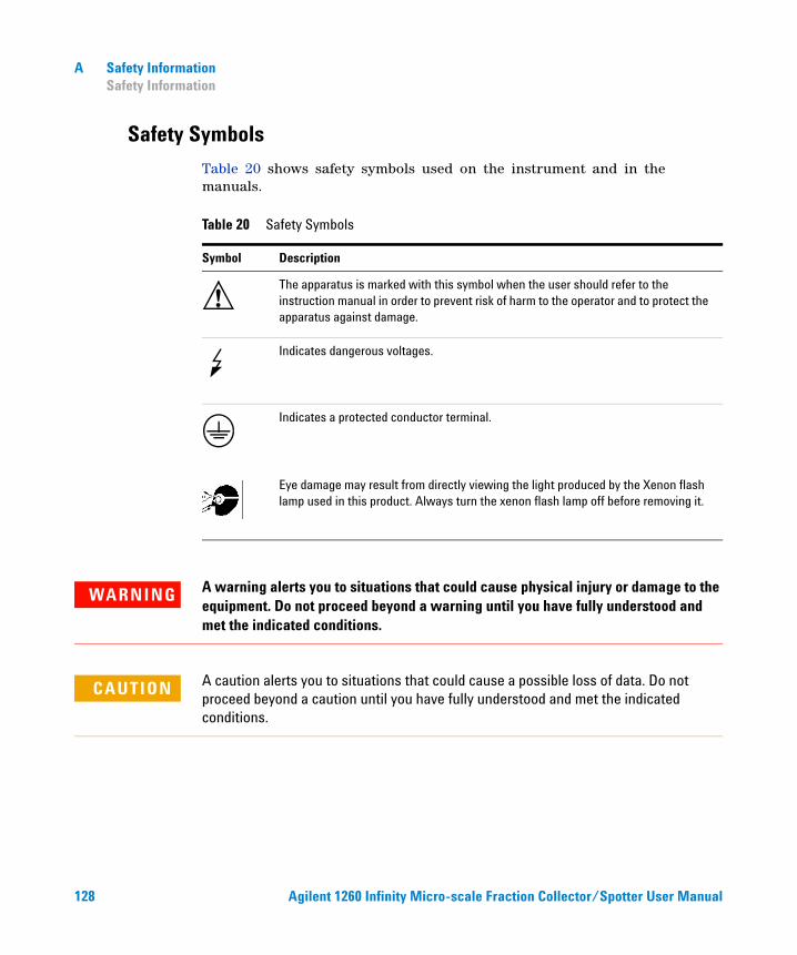
A Safety InformationSafety Information
Safety Symbols
Table 20 shows safety symbols used on the instrument and in the manuals.
Table 20 Safety Symbols
Symbol Description
The apparatus is marked with this symbol when the user should refer to the instruction manual in order to prevent risk of harm to the operator and to protect the apparatus against damage.
Indicates dangerous voltages.
Indicates a protected conductor terminal.
Eye damage may result from directly viewing the light produced by the Xenon flash lamp used in this product. Always turn the xenon flash lamp off before removing it.
!
WARNING A warning alerts you to situations that could cause physical injury or damage to the equipment. Do not proceed beyond a warning until you have fully understood and met the indicated conditions.
CAUTION A caution alerts you to situations that could cause a possible loss of data. Do not proceed beyond a caution until you have fully understood and met the indicated conditions.
128 Agilent 1260 Infinity Micro-scale Fraction Collector/Spotter User Manual
Safety Information ALithium Batteries Information
Lithium Batteries Information
WARNING Danger of explosion if battery is incorrectly replaced. Replace only with the same or equivalent type recommended by the equipment manufacturer. Lithium batteries may not be disposed-off into the domestic waste.
Transportation of discharged Lithium batteries through carriers regulated by IATA/ICAO, ADR, RID, IMDG is not allowed. Discharged Lithium batteries shall be disposed off locally according to national waste disposal regulations for batteries.
WARNING Lithiumbatteri - Eksplosionsfare ved fejlagtic handtering. Udskiftning ma kun ske med batteri af samme fabrikat og type. Lever det brugte batteri tilbage til leverandoren.
WARNING Lithiumbatteri - Eksplosionsfare. Ved udskiftning benyttes kun batteri som anbefalt av apparatfabrikanten. Brukt batteri returneres appararleverandoren.
NOTE Bij dit apparaat zijn batterijen geleverd. Wanneer deze leeg zijn, moet u ze niet weggooien maar inleveren als KCA.
Agilent 1260 Infinity Micro-scale Fraction Collector/Spotter User Manual 129
A Safety InformationRadio Interference
Radio Interference
Never use cables other than the ones supplied by Agilent Technologies to ensure proper functionality and compliance with safety or EMC regulations.
Test and Measurement
If test and measurement equipment is operated with equipment unscreened cables and/or used for measurements on open set- ups, the user has to assure that under operating conditions the radio interference limits are still met within the premises.
130 Agilent 1260 Infinity Micro-scale Fraction Collector/Spotter User Manual
Safety Information ASound Emission
Sound Emission
Manufacturer’s Declaration
This statement is provided to comply with the requirements of the German Sound Emission Directive of 18 January 1991.
This product has a sound pressure emission (at the operator position) < 70 dB.
• Sound Pressure Lp < 70 dB (A)
• At Operator Position
• Normal Operation
• According to ISO 7779:1988/EN 27779/1991 (Type Test)
Agilent 1260 Infinity Micro-scale Fraction Collector/Spotter User Manual 131
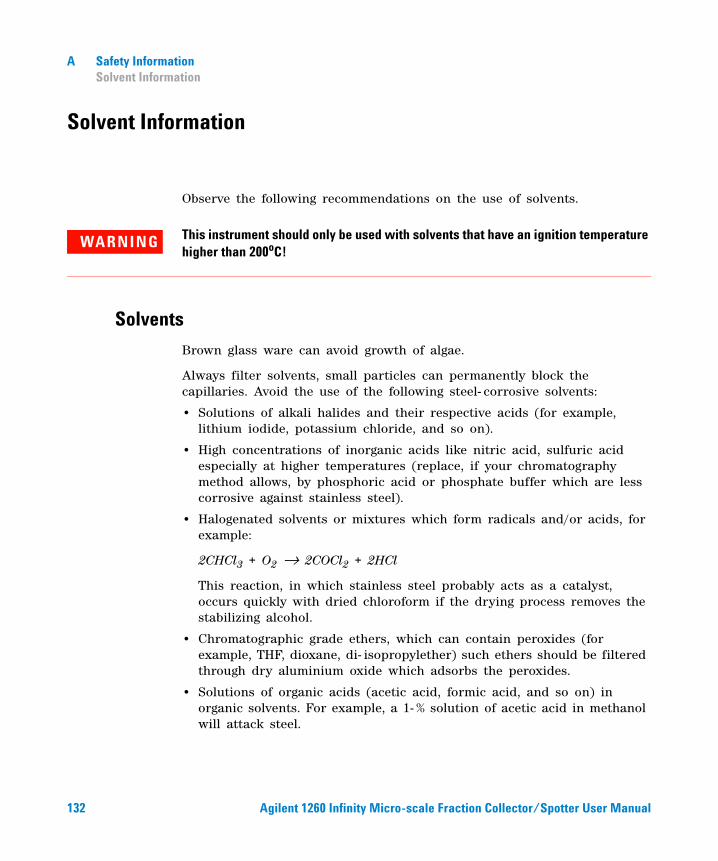
A Safety InformationSolvent Information
Solvent Information
Observe the following recommendations on the use of solvents.
Solvents
Brown glass ware can avoid growth of algae.
Always filter solvents, small particles can permanently block the capillaries. Avoid the use of the following steel- corrosive solvents:
• Solutions of alkali halides and their respective acids (for example, lithium iodide, potassium chloride, and so on).
• High concentrations of inorganic acids like nitric acid, sulfuric acid especially at higher temperatures (replace, if your chromatography method allows, by phosphoric acid or phosphate buffer which are less corrosive against stainless steel).
• Halogenated solvents or mixtures which form radicals and/or acids, for example:
2CHCl3 + O2 → 2COCl2 + 2HCl
This reaction, in which stainless steel probably acts as a catalyst, occurs quickly with dried chloroform if the drying process removes the stabilizing alcohol.
• Chromatographic grade ethers, which can contain peroxides (for example, THF, dioxane, di- isopropylether) such ethers should be filtered through dry aluminium oxide which adsorbs the peroxides.
• Solutions of organic acids (acetic acid, formic acid, and so on) in organic solvents. For example, a 1- % solution of acetic acid in methanol will attack steel.
WARNING This instrument should only be used with solvents that have an ignition temperature higher than 200oC!
132 Agilent 1260 Infinity Micro-scale Fraction Collector/Spotter User Manual
Safety Information AAgilent Technologies on Internet
• Solutions containing strong complexing agents (for example, EDTA, ethylene diamine tetra- acetic acid).
• Mixtures of carbon tetrachloride with 2- propanol or THF.
Agilent Technologies on Internet
For the latest information on products and services visit our worldwide web site on the Internet at:
http://www.agilent.com
Select “Products” - “Chemical Analysis”
It will provide also the latest firmware of the Agilent 1260 Infinity modules for download.
Agilent 1260 Infinity Micro-scale Fraction Collector/Spotter User Manual 133

A Safety InformationAgilent Technologies on Internet
134 Agilent 1260 Infinity Micro-scale Fraction Collector/Spotter User Manual
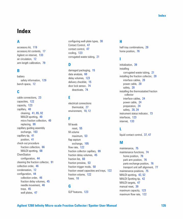
Index
Index
Aaccessory kit, 119accessory kit contents, 17Agilent on internet, 133air circulation, 12arm length calibration, 79
Bbattery
safety information, 129bench space, 12
Ccable connections, 23capacities, 122capacity, 123capillary, 40
cleaning, 41, 65, 92MALDI spotting, 40micro fraction collection, 40replacing, 99
capillary guiding assemblyexchange, 103
capillary tip, 41position, 41
check-out procedurefraction collection, 66MALDI spotting, 68
ChemStationconfiguration, 44
cleaning the fraction collector, 91collection order, 46condensation, 12configuration, 44
collection order, 46fraction delay volumes, 45needle movement, 46trays, 45well plates, 47
configuring well-plate types, 30Contact Control, 47contact control, 47cooling, 123corrugated waste tubing, 21
Ddamaged packaging, 15data analysis, 60delay volumes, 123delivery checklist, 15door lock sensor, 74
deactivate, 74
Eelectrical connections
thermostat, 27environment, 10, 12
Ffill levels
reset, 55fill volume
maximum, 53flap septum
exchange, 105flow rate, 122fraction collector capillary, 99fraction delay volumes, 45fraction list, 60fraction preview, 53fraction trigger mode, 50fraction vessel capacities and trays, 122fraction volume, 122fuses, 10
GGLP features, 123
Hhalf-tray combinations, 29home position, 76
Iinitialization, 39installing
corrugated waste tubing, 21installing the fraction collector, 20
interface cables, 20power cable, 20safety, 20
installing the thermostatted fraction collector
interface cables, 24power cable, 24preparation, 24safety, 20, 24
instrument status indicator, 73interfaces, 123internet, 133
Lliquid contact control, 37, 47
Mmaintenance, 75maintenance functions, 74
home position, 76park arm position, 76parts exchange position, 76transport unit self alignment, 77
maintenance positions, 75MALDI spotting, 42, 52MALDI Spotting tip, 42MALDI targets, 47manual reset, 39maximum capacity, 123maximum flow rate, 122
Agilent 1260 Infinity Micro-scale Fraction Collector/Spotter User Manual 135

Index
method, 48setup, 48, 49
minimum fraction volume, 122missing parts, 15
Nneedle assemblies, 117needle movement, 46
OOnline, 59operating modes, 122
Ppark arm position, 76park transport unit assembly, 34parts and materials, 15, 109
needle assemblies, 117plates, 112transport unit assembly, 117
parts exchange position, 76peak based, 50peakwidth, 41Performance, 122performance specifications, 121
analytical scale, 122physical specifications, 13
fraction collector, 13thermostat, 13
plates, 112position accuracy calibration, 41, 79power consideration, 10power cords, 11power requirements, 10power supply indicator, 72preview, 53
Rrecovery, 52recovery on the track, 52
removingtray compartment divider, 26
repairing the fraction collector, 89repairs
cleaning the fraction collector, 91main procedures overview, 92simple repairs, 90
report, 61reserved locations, 48reset, 39
Ssafety information
on lithium batteries, 129sensor pad, 36shipping, 34simple repairs, 90, 92site requirements, 10slope only, 50specifications, 13, 121spotting adapter, 42spotting rate, 51start location, 56status indicators, 72step commands, 87storage, 12
Ttemperature, 12thermostat
electrical connections, 27threshold
upper, 50tick marks, 61time based, 51timetable, 50, 51transport, 34transport unit assembly, 34, 117transport unit self alignment, 77transporting the fraction collector, 34tray combinations, 29tray compartment divider, 26
trays, 45, 122numbering of vessel positions, 29
trigger modes, 122troubleshooting and test functions, 71
Uunpacking the fraction collector, 15upper threshold, 50
Wwaste port
cleaning, 92waste tubing
exchange, 105weight, 12well plates, 29, 47, 112
384 conical-well plates., 79
Agilent 1260 Infinity Micro-scale Fraction Collector/Spotter User Manual 136

© Agilent Technologies 2010, 2013
Printed in Germany10/2013
*G1364-90013**G1364-90013*G1364-90013 Rev. B
www.agilent.com
Agilent Technologies
In This Book
This manual contains user information about the Agilent 1260 Infinity Micro- scale Fraction Collector/Spotter. The manual describes the following:
• configuration and operation,
• troubleshooting and test functions,
• maintenance and simple repairs,
• parts and materials,
• specifications,
• safety information.