aeronca oleo strut - john propstjohnpropst.yolasite.com/resources/aeronca oleo strut rev 9.pdf ·...
TRANSCRIPT

Aeronca Oleo Strut Maintenance
First Section Original Material by John Baker This Article Assembled and edited by John Propst
Technical Review by Bill Pancake Abstract: This article covers the inspection, maintenance, and overhaul of oleo struts used on Aeronca Chief and Champ aircraft. The primary focus is on the standard struts although there is some additional information related to the no-bounce struts. Forward This article deviates from the standard format for Aeroncapedia documents. The first part of the article is a direct extraction from John Baker’s Hangar 9 Aeroworks web located at hangar9aeroworks.com. This portion of the article was reproduced with permission, from John Baker and is presented in John’s style and format. The second portion of this article is additional related information provided by Bill Pancake and a number of other people via the National Aeronca Association (NAA) site and by people via the fearless Aeronca Aviators (fAA). This document was technically reviewed by Bill Pancake. The document was created in its current format by John Propst. Aeronca Oleo Strut Maintenance by John Baker.
This figure displays the Aeronca landing gear major components. This “Landing Gear Drawing” was extracted from the Aeronca Champ Service Manual
First Section Original material created by John Baker This document assembled and edited by John Propst This document review PENDING by Bill Pancake, and John Baker Revision 9 May 24, 2012
1

Oleo? The Aeronca Champs and Chiefs use the "famous Aeronca oleo landing gear", featuring a hydraulic shock strut with an internal spring. As further explanation - here's the definition of "oleo strut" from the Random House Dictionary:
oleo strut, a hydraulic device used as a shock absorber in the landing gear of aircraft, consisting of an oil-filled cylinder fitted with a hollow, perforated piston into which oil is slowly forced when a compressive force is applied to the landing gear, as in a landing.
I admit I've applied some extraordinary "compressive forces" to the landing gear on my Chief. It's a great landing gear, but it does need regular maintenance. And after 60 plus years, there are some things to look for. I knew that the oleo struts on my Chief had been rebuilt with new bushings just three years prior, but even so, not all was quite as it should have been. What follows is based on my experience. It should help you understand how the oleo struts are put together and serviced. Before you tackle your struts, read this entire article - because what follows does not necessarily proceed in step-by-step order. You should also carefully read the Aeronca Service Manual. All work should be performed or supervised by an FAA certified airframe mechanic, and the proper logbook entries should be made. One more note: the material here applies only to the standard oleo strut landing gear, not the "no bounce" landing gear offered later and found on some Aeroncas. Among other differences, the "no-bounce" gear uses a different, longer but smaller diameter spring that will not work properly in the standard strut. The "no-bounce" landing gear can be identified by a "bulb" located at the lower end of the oleo strut assembly. The figure on the left displays the no bounce gear. And the table below lists the no bounce parts list.
First Section Original material created by John Baker This document assembled and edited by John Propst This document review PENDING by Bill Pancake, and John Baker Revision 9 May 24, 2012
2
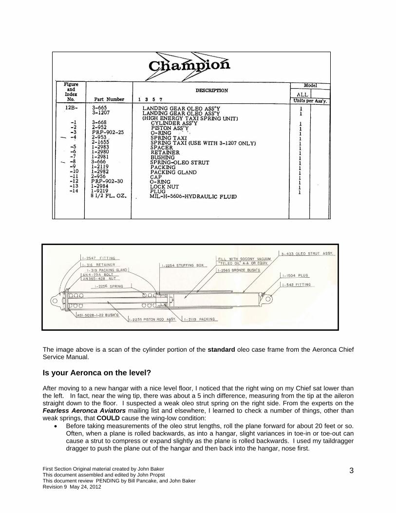
The image above is a scan of the cylinder portion of the standard oleo case frame from the Aeronca Chief Service Manual. Is your Aeronca on the level? After moving to a new hangar with a nice level floor, I noticed that the right wing on my Chief sat lower than the left. In fact, near the wing tip, there was about a 5 inch difference, measuring from the tip at the aileron straight down to the floor. I suspected a weak oleo strut spring on the right side. From the experts on the Fearless Aeronca Aviators mailing list and elsewhere, I learned to check a number of things, other than weak springs, that COULD cause the wing-low condition:
• Before taking measurements of the oleo strut lengths, roll the plane forward for about 20 feet or so. Often, when a plane is rolled backwards, as into a hangar, slight variances in toe-in or toe-out can cause a strut to compress or expand slightly as the plane is rolled backwards. I used my taildragger dragger to push the plane out of the hangar and then back into the hangar, nose first.
First Section Original material created by John Baker This document assembled and edited by John Propst This document review PENDING by Bill Pancake, and John Baker Revision 9 May 24, 2012
3

• Check the length of the exposed strut, below the case frame. I found a difference of about a half inch comparing left to right.
• Check the overall length of the strut, from the top bolt where the strut attaches to the fuselage to the bottom bolt where the strut attaches to the axle. From Joe at Safe Air Repair, I learned that the length of the oleo case frames can vary, so it is not sufficient to only measure the exposed portion of the strut. Again, I found a half inch overall difference between the left and right struts.
• The wing low condition could be caused by a "bent" fuselage, the result of too many very hard landings. Measure from the lower surface of the wing to the upper oleo strut attach bolt. It should be the same for both sides. It was okay on my Chief. Sometimes, a door that does not fit well in the door frame provides a clue that the problem lies here.
• Check that the bolts attaching the case frame to the fuselage is not too tight, preventing the assembly from pivoting freely. This can cause symptoms similar to a weak spring. Things should be tight enough that there is no excess play, but loose enough that the case frame can pivot.
• Check that the upper strut attach fitting is in the proper place. Sometimes an old repair could have been accomplished with little consideration for accuracy. Measuring from the lower surface of the wing to the fitting and comparing both sides will help in identifying this possible problem.
• Check the logs to see if the springs have been changed recently. I found no evidence of that. To make sure, I contacted Tom Miller, who had rebuilt my Chief in 1998 with new bushings, packing, and packing gland. He said he did not replace the springs at that time - the springs were the originals. I even looked at some old photos taken when Tom owned the airplane. It seemed, even then, that the right wing MIGHT be a little lower than the left.
Need parts? Convinced that the problem probably was a weak spring, I called Safe Air Repair for a pair of new springs and new packing. The part number for the springs is 1-2256. The packing, part number 1-2119, contains enough packing for both struts. Cost for everything, with shipping, was a little over $100. Safe Air Repair had a great reputation for quality and service. During March of 2005, Safe Air Repair was sold to Wag Aero. Wag Aero will carry the full Safe Air inventory. Univair is another source for parts. Service procedures for the oleo struts are found in the Service Manual, but it helps to know a few tricks not found in the manual.
Since the bushings on my struts had been replaced when the plane was rebuilt in 1998, I did not replace those. My oleo struts were tight in the case frame, with little or no play. If things are loose, you may need new bronze bushings (part number 102565). I understand that these bushings can be difficult to remove, and often must be cut out.
First Section Original material created by John Baker This document assembled and edited by John Propst This document review PENDING by Bill Pancake, and John Baker Revision 9 May 24, 2012
4

First Section Original material created by John Baker This document assembled and edited by John Propst This document review PENDING by Bill Pancake, and John Baker Revision 9 May 24, 2012
5
The Aeronca Manual cautions: "THIS REPLACEMENT [of the bushings] SHOULD NOT BE ATTEMPTED BY ANYONE OTHER THAN AN AIRPLANE MECHANIC." When the struts on my Chief were last rebuilt in 1998, the packing and packing glands were replaced, but the packing should be replaced any time you have the strut apart. Safe Air Repair used to be able to repair the bushings if this was needed. You can see if Wag Aero, the firm that purchased Safe Air Repair, provides the service now. Another source for this service is David Rude, 919-365-3063, email [email protected]. Dave is an A&P/AI and does oleo work and case frame repair. Speaking of parts, when you have things apart, check the condition of the retainer at the top of the oleo strut. This is part number 1-316 in the drawing. Aeroncateer Carl White passed along the following information: "I've seen some of the aluminum top retainers that did not have a bevel cut on the spring side as well as some of the really old phenolic types. Think most of the current replacement items have the bevel. If one runs into a retainer that has mushroomed and does not have the bevel, about all that one can do is to use a slide hammer to pull the retainer out of the cylinder past the bushing. Several bad things can happen if brute force is required; the worst is that the bronze bushing will be pulled out along with the retainer. If this happens, the likelihood of the reuse of the bushing is remote. Wish someone smarter than me could figure out a way to remove a damaged retainer without doing harm to the bushing. Bushing replacement is not a fun thing. By the way, if one encounters one of the original phenolic retainers, I would suggest replacement with the "modern" aluminum type." And speaking of replacement parts, early Champs and Chiefs had a "laminated synthane" fiber piston head as part of the 1-2255 piston rod assembly that should have been replaced long ago with an aluminum piston head. This was addressed by Airworthiness Directive 47-20-02 which applies to 7AC airplanes having serial Numbers 226 to 3721 and 11AC airplanes with serial numbers 1 to 351. This replacement should have been done "not later than August 1, 1947," so you should not have a fiber piston head on the oleo strut assembly your airplane. Regarding that airworthiness directive, oleo expert David Rude offers this clarification: "Yes there is an Airworthiness Directive (AD) and a Service Bulletin (SB) on this oleo. Occasionally there is confusion over what part the AD is referring to. The SB makes it very clear; the AD is a little sketchy. The AD is not referring to the "donut" on top of the spring that is plainly visible (part number 1-316). Apparently that part came in fiber or aluminum as mentioned previously and that perhaps is why it is mistaken for the part referred to in the AD. The AD does refer to the piston inside the oleo you cannot plainly see. You have to drain the oil, remove the spring then slide the rod all the way down and look in the filler hole to see the part covered by the AD. You may have to clean all the gunk out to see what you're looking for, but look for a shiny aluminum surface (rather than a dull fiber one). I use a penlight to shine in, makes it easier to see. If you see fiber you need a snare cable or replace the piston." Need a Lift? Servicing the struts requires that the plane is supported so that the landing gear is not under load and is off the ground. There are several methods that can be used for this, and what works best for you may be different than the method I used.
• One method is to use an engine hoist to lift the front of the aircraft via the engine mount. If you have one handy, this is a very secure method and the method I would have used if I had a hoist available. (See the postscript at the end of this page - when it was time to do this again a couple of years later, I did use a hoist). Just be sure to use wide nylon straps or rope around the mount and be careful to lift near the mount attach points, NOT near the center of the engine mount tubes. You don't want to bend that engine mount.
• Method two involves pulling the opposite wing down to lift the other side. This sounds brutal but is reported to be quite acceptable. In fact, it is a method suggested in the Aeronca Manual for raising the gear off the ground. You'll need something near the floor or ground to connect to (maybe the bumper hitch on your pickup truck), and use a come-a-long connected to the tie-down ring to pull that wing down until the opposite tire is clear of the ground.

• I chose method three, a fixture (that I'll call a wing jack) to support the wing at the wing strut attach point. Since I would be working in a hangar with no wind, I felt this was safe. I also planned the work to minimize the amount of time the wing was lifted. I built the wing jack from 2x4's and plywood, as shown in the photos. I used a vertical 2x4 83" tall with a base 24" wide, gusseted with plywood, all glued and screwed together to make a sturdy, inverted "T". Where the vertical 2x4 supports the wing, I cut a concave section out to support the strut, so the strut could not slip off the top of the 2x4. I used a few pieces of rubber tape for a non-slip, non-scratch surface. The photos tell the story best.
I made my lift 83" tall, which lifted the tire off the ground just a few inches. I suggest a slightly taller lift, perhaps 86” or 87" for a Chief. I'll explain why later. A lift for a Champ would need to be even taller. To lift the wing, first place wheel chocks on the opposite side main wheel and tailwheel. Then have one or two strong lifters lift the strut, just a few inches inboard of the tie down ring. While the strong guys lift the wing, you (the smart one) slide the wingjack into position, just inside the tie down ring and strut fitting. Set the wing carefully down on the wingjack, with the base of the wingjack squarely on the floor and the vertical 2x4 in a truly vertical position. This arrangement worked out just fine for me, but I would not recommend doing this outside where a breeze could upset things. Here's another variation on the same theme, this arrangement by Dan Jones from Alberta, Canada. He actually used a combination of methods two and three. It helps to have a spare Continental W670 radial lying around the shop to use as "dead weight". Dan explains:
First Section Original material created by John Baker This document assembled and edited by John Propst This document review PENDING by Bill Pancake, and John Baker Revision 9 May 24, 2012
6
"The A frame trestle is 2x4's bolted together for stiffness and it's the absolute bare minimum height for a Champ, 87" from the apex of the saddle to it's base. You can't swing the gear leg out - I opted just to remove the case frame completely - my logic being that the lesser the angle I had to trestle the airplane at, the less load I'd put on the other gear leg and it's packing. I jack the airplane with a small jack and then slip the trestle in place and lower the airplane down onto the free standing trestle. Then I use a heavy weight (I used a time-expired W670 Continental) tied down to the low wing's tie down point in case the trestle slips. It's all very easy to do solo."

First Section Original material created by John Baker This document assembled and edited by John Propst This document review PENDING by Bill Pancake, and John Baker Revision 9 May 24, 2012
7
But before you lift that baby... Remember that we're working with springs here, and that can be tricky. You o compress the new spring so that you can install it on the strut. You may as well get re rt taking things apart. The new springs I received were 11-1/16" tall. To fit themcompress them to about 10-1/2”. The method I used successfully was reRichard Jeffryes. It worked great. I went to my local hardware store and bougfeet long, with nuts and washers. I ran the rod through the new spring, with a After tightening the nut so that the spring was compressed to about 10-1/2”,though the coils to hold the spring in the compressed state. Then I loosenethreaded rod. Cool - I now had a shorter spring that I could fit onto the strut
will need a way tdy for this before you staa
on the strut you will need to commended by Aeroncateer ht a half inch threaded rod, 2 nut and washer on each end. I used safety wire wrapped d the nuts and removed the piston rod with no pain. The
first photo below shows the spring compressed using the threaded rod. The second photo shows one spring "au natural" and the second held in the compressed state with safety wire. I used a safety wire in three different places around the circumference of the spring. The old spring that I removed was 10-1/2" long, 9/16" shorter than the new spring. Richard Jeffryes has measured a couple of new springs and they were 11-1/8" tall.
There are other methods that work for compressing the spring; creativity is encouraged! Aeronca owner Carl White likes to use a 36" bar clamp. He reports: "I use a 36" bar clamp to compress the spring enough to

First Section Original material created by John Baker This document assembled and edited by John Propst This document review PENDING by Bill Pancake, and John Baker Revision 9 May 24, 2012
8
remove and replace the upper pin. The trick is to get the retainer to slide in the spring while keeping the alignment with the hole in the shaft. I find it best to do it flat on the bench with a sandbag on top of the spring to keep things in place in case the clamp slips. The sand bag is fairly important in case that sucker slips and flies across the shop. I just like the bar clamp method over the safety wire as it allows micro-adjustment of the spring seat. Just crank it in until it fits." I also liked another story from Carl: "I once replaced a spring in the field by jacking up the Suburban and putting the assembly between the frame of the “burb” and the ground and then letting the jack down until the pin could be driven out smoothly. Reversed the process for install. Necessity is a mother!" While we're talking about springs, you should know that it is important that the springs not be too short. New springs should be around 11-1/16" to 11-1/8" long. Aeronca owner Richard Jeffryes says, "When they get too short, they can rattle against the piston shaft and wear it, and they can also hammer the top of the oleo." Richard says he has seen spacers made, as well as taller packing glands. But the best bet (and the approved method) is simply to buy new springs. Time to take things apart - removing the Oleo Piston Assembly
• If you have wheel pants, take them off before you begin. Duh...
e was 83" tall, yours should be taller), I did not
e it a
back in. Hard to tell. On the right, the empty case
• Remove the fairing at the fuselage/landing gear intersection (note that not all Champs and Chiefs have fairings).
• Remove the AN6-23 bolt and AN310-6 nut that attaches the bottom of the oleo strut to the axle. • If you have a wheel pant bracket, this will be removed at this time also. Keep track of washers -
how many and where they go. The axle is now free to drop to the ground or floor. • Remove the AN4-23A bolt and lock nut at the top of the strut. This allows the oleo strut assembly to
be pulled out of the case frame. Swing the case frame to a horizontal position to do this. • Because I did not make my wing jack tall enough (min
have enough clearance to swing the gear without it hitting the wheel and tire. I had to remove the wheel, which also meant removing the Goodyear brake disc, retaining buttons and clips. Make your wing jack tall enough and you won't have to do this.
• Pull the oleo strut out of the case frame. You may have to wiggle things a little, maybe rotatlittle. Mine came out pretty easy. If yours is reluctant, David Rude suggests inserting a 3/8" bar or long bolt in the strut-to-axle hole at the bottom of the strut and tapping on the bar with a rubber mallet to pull the oleo strut out of the case frame.
In the photo below, I pull the oleo piston assembly out of the case frame, while my friend Tom Crone upports the case frame. Or maybe I'm putting the strut s
frame.
First Section Original material created by John Baker This document assembled and edited by John Propst This document review PENDING by Bill Pancake, and John Baker Revision 9 May 24, 2012
9
The O
you removed earlier will go though the case frame, the retainer, the piston rod, and the bushing to hold the entire mess together. To remove the spring, you drive out the bushing. Use a punch or pin that is
careful not to d you will reuse it. Once the bushing it driven out, the retainer can pop ring. Assembly works just the reverse, after you installed the compr spring as shown below. It works best if you take a file and create a slight taper on the edge of the bu ing before reinstalling. We found that the piston rod wanted to slide back into the strut cylinder while we w stalling the spring. To pull the piston rod back to its fully extended length, we simply tied a piece of safety wire to the top where the retainer and bushing is attached, and used the safety wire to pull the piston rod to the extended position. Then we were able to easily slide the retainer onto the end of the rod.
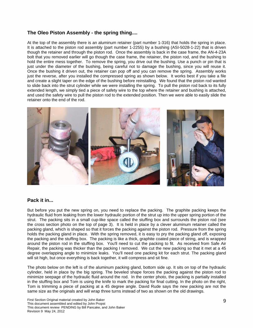
Pack it in... But before you put the new spring on, you need to replace the packing. The graphite packing keeps the hydraulic fluid from leaking from the lower hydraulic portion of the strut up into the upper spring portion of the strut. The packing sits in a small cup-like space called the stuffing box and surrounds the piston rod (see the cross section photo on the top of page 3). It is held in place by a clever aluminum retainer called the packing gland, which is shaped so that it forces the packing against the piston rod. Pressure from the spring holds the packing gland in place. With the spring removed, it is easy to pry the packing gland off, exposing the packing and the stuffing box. The packing is like a thick, graphite coated piece of string, and is wrapped around the piston rod in the stuffing box. You'll need to cut the packing to fit. As received from Safe Air Repair, the packing was thicker than the packing I removed. We cut the new packing so that it met at a 45 degree overlapping angle to minimize leaks. You’ll need one packing kit for each strut. The packing gland will sit high, but once everything is back together, it will compress and sit fine. The photo below on the left is of the aluminum packing gland, bottom side up. It sits on top of the hydraulic cylinder, held in place by the big spring. The beveled shape forces the packing against the piston rod to minimize seepage of the hydraulic fluid around the rod. In the center photo, the packing is partially installed in the stuffing box and Tom is using the knife to mark the packing for final cutting. In the photo on the right, Tom is trimming a piece of packing at a 45 degree angle. David Rude says the new packing are not the same size as the originals and will wrap three turns instead of two as shown on the old drawings.
leo Piston Assembly - the spring thing....
At the top of the assembly there is an aluminum retainer (part number 1-316) that holds the spring in place. It is attached to the piston rod assembly (part number 1-2255) by a bushing (ASI-5028-1-22) that is driven though the retainer and through the piston rod. Once the assembly is back in the case frame, the AN-4-23A bolt that
just under the diameter of the bushing, being amage the bushing, sinceoff and you can remove the sp
essed shere in

First Section Original material created by John Baker This document assembled and edited by John Propst This document review PENDING by Bill Pancake, and John Baker Revision 9 May 24, 2012
10
First, notice the coffee can. That's important; because you need to drain the hydraulic fluid before you pull
rew the let it drain until empty, more or less. On the left you see the new spring d held tight with safety wire. That's Tom with a knife cutting a 45 degree angle opacking, so that the packing overlaps. The hammer was used to flatten the packibetter. Another piece of packing, more than enough for the second punch and the yellow handled screwdriver were helpful for pressing the palike area at the top of the cylinder. In the background, you can see the oleo and retainer removed, and the piston rod pulled only about one third
The workbench photo shown below is full of interesting things, and I'm not talking about the dirty shop rags.
pry the packing gland off. The plug is at the bottom of the strut. Unsc plug over the coffee can and ready to install, compressed an
n the other end of the graphite ng a little so it fit in place
strut, is lying nearby. The blue handledcking into the stuffing box, a cup-
piston assembly, with the spring to half way out of the cylinder.

First Section Original material created by John Baker This document assembled and edited by John Propst This document review PENDING by Bill Pancake, and John Baker Revision 9 May 24, 2012
11
Once the packing is in place, you can slip the aluminum packing gland over the piston rod, capping the retainer
and the piston rod, and drive the bushing back in with a wire and remove the wire from the spring. Watch your eyes a es or turn your head - because the wire is under pressure and will snap In May of 2010, I received an email from John Price offeri ng the packing. First, he provided a PDF scan of an Aeronca eo Graphite, which provides details of the 3/8" packing installatio m McMaster-Carr in 5, 10 and 25 foot lengths. 5 feet will cost yo r or Wag-Aero will sell you Is it legal to use it? My take is yes, oduct Interchangeable with Johns Manville." Here's the og: http://www.mcmaster.com/#compression-packing/=72krmj
ow you can fill the strut with oil. We chose to do this while the strut was on the bench. You could just as asily fill the strut after it is installed back on the airplane. Unscrew the plug, and fill with hydraulic oil. My 1AC Aeronca Manual says to fill with "Teleo" oil or any good hydraulic oil. We used standard MIL 5606 ydraulic fluid. Later, I learned that Carl White suggests using John Deere "Hy-GARD" multipurpose ydraulic fluid. He reports that the John Deere fluid is less messy, tends not to leak as much or leave a sidue, and has the same specs as the "approved" Socony-Vacuum "Teleo" oil mentioned in the service anual. Aeronca owner George Edgerton has tried both MIL 5606 and the John Deere "Hy-GARD" and refers the latter, reporting that "Bottom line is that the struts work extremely well with this oil---light years etter than before." Others have suggested motorcycle fork oil. Dave Rude, who rebuilds oleos as a side usiness, says that he uses MIL 5606. He points out that the 7EC Manual specifies 5606 for the "no-ounce" oleo, and so he keeps a supply on hand and uses it for all of his struts. MIL 5606 is the "standard" nd most A&P mechanics are comfortable sticking to that.
he photo below shows us filling the strut. We used a turkey baster for the job. It worked great. For those of you who may have seen instructions to fill the strut with 8.5 ounces of fluid, you should know that that instruction applies to the "no bounce strut", not the standard strut. If you have the standard strut, fill it up! By the way.... there have been reports of major damage to the oleo assemblies from lack of oil. Some Aeronca owners have reported that the upper retainer will "mushroom" from the pounding it receives if the strut does not have enough oil. If this happens, repairs are difficult and expensive.
packing in the stuffing box. Then, install the spring and the aluminum retainer. Carefully line up the punch. Once that is all back together, cut the safety
s you cut the wire - wear safety gogglwhen you cut it.
ng some additional information regardiDrawing 1-2119, Packing, Landing Gear Ol
n. John notes that packing is "available frou a whole lot less than 2 of what Univai
since 1-2119 specifies "Commercial Prlink to the McMaster-Carr catal
Ne1hhrempbbba You may notice some initial leaking after installing new packings. I experienced a bit of leaking at first, but it did not last. Richard Jeffreys reported, "My no-bounce gear did [leak] when I first installed them, but then the packing took a seat and they quit. A little oil looks like a lot." It's important that the strut is filled COMPLETELY with fluid. Lift the strut high enough so that it can be completely filled. An Aeronca Service Letter (#40, September 8, 1948) included the following information: "The landing load factor runs extremely high when the fluid gets low in the oleos - 3/4 full is almost as bad as no fluid at all! Oleos must be kept full of fluid." After filled, of course, screw the plug back in nice and tight. T

First Section Original material created by John Baker This document assembled and edited by John Propst This document review PENDING by Bill Pancake, and John Baker Revision 9 May 24, 2012
12
About that plug... The little plug at the bottom of the strut fits into a hole with a 1/8" NPT thread. Be sure you are using the correct size plug. My Chief has brass plugs, though one owner has suggested using a steel plug. Using a plug of a softer metal than steel (brass or aluminum) offers several advantages: less chance of damage to the strut from cross threading, less likelihood of the plug welding itself to the strut, and the ability to seal better with less torque. It would also be easier to drill out a damaged brass or aluminum plug than a steel plug. The style of plug seems to vary. My plugs were simply slotted for a standard screw driver. Many have the square head plug - an AN913-1 or MA20913-1 type. Highly recommended is a brass plug with an internal wrenching hex head for use with an allen wrench. These are available from McMaster-Carr, part number 9171K251, and use a 3/16" allen wrench. I ordered some and will use them the next time I refill the struts. David Rude likes to use an AN932-2D aluminum plug, also referred to as an MS27769-2D hex plug. In any case, some thread sealer, such as Loctite 565 NST or Tite Seal compound, is a very good idea. A leak that you might think is coming from the graphite packings - and thus prompting a complete disassembly of the strut to replace the packings - could be from something as simple as a leaking plug. Don't ask me how I know. Back Together... Once the assembly is back together, just slide it back into the case frame. You might need to wiggle it a bit. Be SURE that you get things lined up so that the AN4-23A bolt at the top of the strut goes through the bushing and the retainer. You must insert the oleo strut far enough into the case frame for the bolt to engage the strut. If the bolt misses its mark, your landing gear will fall off when you take off, very embarrassing. Also make sure that the fill plug at the bottom of the strut is in the up (or outboard) position, so it can be checked and filled as necessary. Re-attach the axle with the AN6-23 bolt (with the washers in the right place and the wheel pant bracket in place). The bolt should be snug enough so there is minimal play, but loose enough that the axle can pivot.
this case, the grease found its way up into the spring area, completely filling it, and eliminating all chance for
With everything back together, look for the Alemite (Zerk) grease fitting on the front lower end of the oleo case assembly. The Chief Service Manual says to apply AN-G-3a or AN-G-15 grease (apparently no longer available) with a gun until it is forced out of the bottom of the oleo case assembly. I just used the general purpose water-resistant grease that was in my grease gun. If you want to buy aviation grease, Aeroshell 22 or Aeroshell 6 would be appropriate. On the lubrication chart published by Shell in 1948, they indicate Aeroshell Grease 6 in the Aeronca Oleo Assembly Piston. Carl White says he does not trust the Zerk fitting to lubricate the full circumference of the strut, and instead gives the strut a light coat of grease before installing it (after carefully cleaning the case). Carl also suggests lightly coating the spring. Don't get carried away with the grease gun - a few shots should do it if you have given the strut a light coat of grease before installation. I heard a story of someone using two cartridges of grease with an air-powered grease gun. In

First Section Original material created by John Baker This document assembled and edited by John Propst This document review PENDING by Bill Pancake, and John Baker Revision 9 May 24, 2012
13
y." Most people recommend 4-5 shots of grease, ssuming you have greased the strut before inserting it into the case frame. At any rate, with the strut
level? With the new spring installed, mine as.
weak spring - again! In fact, it had with the tape measure showed the 's going on? At Oshkosh 2005 I with Joe at Safe Air Repair. The
re slightly undersized in thickness, hose who ended up with the bad issed out on getting replacement assured me that the springs now
1-2119 packing kit. Prices at ike Utley would be a good contact
ca parts or about the transfer of Aeronca related parts to ag Aero from Safe Air Repair. His phone number is 1-800-558-6868 (Ext. 142). E-mail is [email protected].
hile waiting for the new parts, I stopped at my local John Deere dealer and picked up a gallon of Hy-GARD ydraulic oil. Part number for this oil, promoted as a multipurpose "Transmission and Hydraulic Oil," is Y6354 for the gallon jug. Cost for the gallon was $7.77, a bit less expensive than buying MIL 5606 by the uart from the aircraft supply houses. The parts came from Wag Aero quickly, but I procrastinated about oing the work. Finally, a month later in October, 2005, I got to work. I decided to use a hoist (also called a
shop crane) this time, and found one on sale at my local Harbor Freight store. Seemed like a good investment, since I will use it often enough. This made the job much easier, and enabled me to do the job "solo". I used a heavy duty nylon "tow strap" that I picked up at the local hardware store. After fretting about this, my friend Claudio tied a nice double knot in the strap to shorten the working length to about two feet. I slipped this under the engine mount tubes where the mount meets the engine. To help stabilize the aircraft, I chocked the tail wheel. I also used a tie-down strap between the opposite wing tie-down ring and a heavy stationary object on the floor (my air compressor served the purpose) to help keep the opposite wing low and to further stabilize the airplane when hanging from the hoist.
This method of lifting the aircraft worked great and I was able to lift the plane high enough that I could swing the strut out without removing the wheel assembly from the axle. Since the packing had been recently replaced and was well seated, I decided not to replace the packing this time, but simply replaced the spring with the new one. Again I used the safety wire method to compress the spring. Everything came apart and went back together easily and quickly. I drained the old hydraulic fluid from the strut and replaced it with John Deere Hy-GARD hydraulic oil. I cleaned out the case and spread a layer of grease on the strut before reinstalling. After five shots with the grease gun, I was good to go. Measuring the distance from the floor at the wing tips, the plane was once again "on the level." ****** End of John Baker’s Web presentation**********
the strut to work properly. So... don't take at face value the instruction in the Service Manual to apply grease "until it is forced out of the bottom of the oleo case assemblalubricated and installed, you're done. Now check those measurements again. Is your Aeronca on the w Postscript... After less than two years with the new spring (I only installed a new spriright wing was down again, and the oleo strut was showing evidence of a gradually been getting lower and lower over the last year or so. A checkright wing was again about 5 inches lower than the left at the tip. Whatspoke with Mike Utley of Wag Aero about the problem and he followed upword is that around 2000 or 2001 there was a batch of springs that weand so were not quite up to specs. Safe Air sent out new springs to tsprings. Apparently the ones I received were in that weak batch and I msprings. Mike explained all of this when I called in late August 2005. Hein stock at Wag Aero met specs, so I ordered another 1-2256 spring and the Wag Aero were good and service was very good as well. By the way, Mat Wag Aero if you have questions about Aeron
ng on the right side), I noticed my
Wm WhTqd

First Section Original material created by John Baker This document assembled and edited by John Propst This document review PENDING by Bill Pancake, and John Baker Revision 9 May 24, 2012
14
Additional information on Aeronca oleo Struts
but I was wrong about that.
fill.
d not normally be required to be changed since there are not products of combustion in the g will get worn into the oil and that will dirty it a bit. Changing the oil is a good thing and a
ave Rude
rease
The following information was provided by David Rude via the fAA website. David is recognized within the Aeronca Community as an expert on oleo struts and has a business related to oleo rebuilding, bushing removal and inspection, and case frame repairs. Additional information can be found in the Aeronca Aviator newsletter published by the Aeronca Aviators Club.
1) Regular oleos need to be filled to the top, i.e. completely full. The manual says this. Last year I posted a thread on the NAA forum telling of my experiences with regular oleo levels. Again regular oleos need to be filled to the top. That seems to take 10 ounces. Here are some observations that are in the NAA thread. When you fill them to the top and if they initially leak at the packing then they seem to leak only until they have 8.5 ounces in them. For a period of time I had been convinced that 8.5 was the correct fill amount because of this
2) No-bounce/long stroke oleos need to be filled to 8.5 ounces. Drain out all of the old oil, then refill. One can make a dipstick for checking this in the shop but on the plane it seems best to completely drain and then re
3) The fluid shouloleo. The packinleaky packing can let stuff in too. Most often when I see gunky stuff in the oil it did not leak in but rather it was put in by a human. 4) Get a service manual, if you are working on this stuff you need to have a manual and the law requires that you have it (far part 43.13a), they are available from the Aeronca Owners Club website (http://www.aeronca.org/Store.html), Univair, probably ESSCO.
Hope this helps. D G
number of questions and ated to greasing Aeronca oleo truts.
oger Anderson submitted this comment: “I'm sure most already know this...and correct me if I'm wrong...but in ne instance reference oleo maintenance in the manual, following it can make a mess. It says reference the oleo, "apply rease with a gun until it is forced out of the bottom of the oleo case assembly". Nine years ago I tried that. A gun of rease later, and no grease yet showing out the bottom, I stopped. I still have grease dripping out to this day. What's e correct annual greasing procedure?”
arl White submitted this comment: ather than trust the grease fitting to distribute the grease the full length and diameter of the cylinder, I remove the ylinder from the gear leg and slather some grease on it by hand. When you do the annual or 100 hour wheel and fluid
A comments have been posted on various sites rels Roggth CRclevel inspection there are only two more bolts to remove and replace the cylinder and lube and inspect. On JYD the zerks serve only to plug the holes. David Rude submitted this comment: I like Plain Carl's method of greasing by rubbing the grease on by hand if that includes greasing the spring too. IMHO the springs rub against the case frame and need some grease for that as well as for corrosion protection. The no bounce springs rub against the case frame the most of the two and both types have a spring to operating rod wear so we need a little grease inside the spring too. The oleo tube to bronze bushing is the most obvious wear surface and Carl's grease method works well for that. Pumping the tube full of grease with the zerk fitting is mechanically prudent as long as the oleo to case frame clearance is enough to allow any compressed grease to escape at landing or taxi time so there in no hydraulic lock from trapped grease. Probably there will not be too much compressed or trapped grease on landing or

First Section Original material created by John Baker This document assembled and edited by John Propst This document review PENDING by Bill Pancake, and John Baker Revision 9 May 24, 2012
15
loader backhoe. Don't reject using the manufacturer’s service manual ecause you find one apparent flaw, and I am not so sure that it is a real flaw. Their method will work. We may just not
ude Inc. endell, NC
taxiing since we generally lubricate the assembly when it is nearly compressed all the way anyhow and any further compression of the oleo will likely occur during taxiing which will compress slowly and the grease will be able to ooze out. Oh yeah, but the oozing is what we don't like. :-) Its a compromise isn't it? Good lubrication or a nice neat look. I have the same issue with my tractors, and blike it. Hope this helps; anyhow that's what I think about it. David [email protected] When Bill Pancake was asked about greasing oleo struts, Bill said that he normally adds a couple squirts of grease from the grease gun during the annual inspection. Bill said that he likes the idea of manually applying a coating of grease to the spring and oleo piston assembly, but at the same time he has a concern that whenever the oleo assembly is removed from the landing gear, there is a remote opportunity for improperly reinstalling the bolt that secures the oleo assembly to the top of the landing gear. One method to reduce this risk is to install the bolt or a punch or screwdriver blade in the hole before installing the oleo strut, and then inserting the oleo until there is positive indication that the oleo assembly contacts the punch or screwdriver blade. The punch or screwdriver is then removed and the oleo is inserted an additional half inch or so until the through bolt can be visibly inserted into the top of the oleo assembly. It’s still not level What do you do if you’ve tried all the previously suggested repair techniques and your aircraft still tilts to the left or right? This was a
een totally replaced wit problem that the author had following the restoration of his champ. One oleo had h a new assembly. The other was inspected and overhauled with many new
e photo on the left shows the brass ricated to raise the low wing. It
was somewhat a guessing game to decide how
dabout the spring. Note that three single compressed. After reassembly and reinsta
bcomponents, including a new spring. Both oleo assemblies measured identical. Likewise the aircraft case frames appeared identical. Dimensional checks of the airframe including measurements from the case frame
attachment point to wing spar attachment point likewise revealed no problems. The issued was discussed with Bill Pancake. Bill’s feedback was that no matter how careful we are at trying to match the left and right sides of the aircraft, sometimes they just end up listing one way or the other. One method for correcting this problem is to make the effective length of the oleo spring on the low side of the aircraft longer by inserting a spacer between the oleo spring and the upper end retainer. Thspacer that was fab
thick the spacer should be. The lower wing tip was about 3” lower than the higher wing tip. When the lower wing was raised until it was level with the higher wing, measurements of the oleos suggested that a 1/4" spacer would come close to correcting the problem. As shown in the photo,
with three multiple wraps of safety wire located equally spaced loops of .041 safety wire were not adequate to keep the spring llation of the oleo strut, the aircraft now sets relatively level.
the spring was compressed and secure

First Section Original material created by John Baker This document assembled and edited by John Propst This document review PENDING by Bill Pancake, and John Baker Revision 9 May 24, 2012
16
Photos ometimes a photo is ne number of photos of
were used for the assembly of oleo struts. Note that the left forging is drilled and tapped
that there where three different components originally fabricated from fiber (micarta) and later fabricated from aluminum.
S eded to better understand how devices function. Below are a various oleo components.
These two photos show new forgings that
for the fill plug.
The photo on the left shows an old fiber packing gland and a new aluminum retainer. From this photo and the next few photos, note

First Section Original material created by John Baker This document assembled and edited by John Propst This document review PENDING by Bill Pancake, and John Baker Revision 9 May 24, 2012
17
n the
ft, submitted by one of the NAA participants, shows both fiber and aluminum oleo
his photo, submitted by Nathan Hammond, shows many of the components that go into a completely assembled oleo assembly.
The photos below show both an aluminum and fiber piston. Note the cracks in the fiber piston shown oright.
This photo below lecomponents. The photo below right, also submitted by a NAA participant, shows the method for inspecting an oleo piston through the oil fill hole to determine if the oleo piston is fiber or aluminum. The photo shows a fiber piston seen through the oil fill hole.
T

First Section Original material created by John Baker This document assembled and edited by John Propst This document review PENDING by Bill Pancake, and John Baker Revision 9 May 24, 2012
18

First Section Original material created by John Baker This document assembled and edited by John Propst This document review PENDING by Bill Pancake, and John Baker Revision 9 May 24, 2012
19
leo OverhaulsO hile a great deal of information has been presented related to the inspection and repair of Aeronca oleo
truts, it is not a simple or easy task that can be safely and correctly performed without adequate training,
bled, or installed oleo can result in catastrophic failure of the aircraft and serious or fatal injury to the a prof o
inspection and repair. As mentioned earlier, David Rude is one such person who provides this service. The following information was provided by David Rude to Jim Spree some time back related to typical costs associated with oleo work. It is presented here to get you in the ball park. You should contact your I/A for specific information related to the time and costs associated with oleo repair.
I hope this helps readers have an idea about oleo work costs. I normally work on an hourly basis
and it typically comes out very much like indicated below. I am an A&P/IA. I put some average
charges for the work so it gives an idea of cost. Some of the work overlaps so it's not alway correct
to add the prices together. Shipping back has to be added in. Call before sending anything.
If the oleo leaks oil you probably need seals & packings, this is for one oleo;
Disassemble and inspect one oleo strut $35
606 fluid $35
parts for above (only FAA/PMA) $22
total $92
If the oleo is loose in the case frame (landi m
The fabric on the case frame gets destroyed during this process.
Metal covers must be removed, prices do not include removal.
Clean the case frame, oleo and spring before sending it.
remove bushing from one case frame $25
install new bushing in one case frame $25
hone one bushing id to size $40
parts for above (I only use FAA/PMA $41
total $131
If the case frame rear tube is rusted, this is for one case frame
repair rear tube on one case frame with larger tube splice method $86
fill out 337 $25
tubing $6
total $117
David Rude ------------------
Wsproper tooling, and a complete understanding of each and every component. An improperly repaired, assem
aircraft passenger or pilot. If in doubt, it is best to seek essional AP I/A with knowledge of ole
s
Clean the case frame, oleo and spring before sending it.
Reassemble one oleo, install o-rings & packing,
add 8.5 oz H5
if you need a spring that can add another $50-$100
ng gear vee), this is for one case fra e

Oleo Repair at Bill Pancake’s Shop Anyone who has ever visited Bill Pancake’s shop knows that he has a tool or fixture to
repair or manufacture essentially every part of an Aeronca aircraft. Many of these
been designed and manufactured out of necessity over the years. The following provide
brief glimpse of some of the tools and techniques that Bill uses in the repair of Aeronca
struts.
The first tool shown is a simple mandrel that has a tight fit into the end of the oleo
the brass bushing remov
mandrel, which has a loos
fit, is inserted into the frame
whenever the small roun
tube is welded or reweld
main oleo tube. This helps
the welding process from di
the oleo tube. Once the weld
has been completed, Bi
fixture on his hand arbor pre
extracting the mandrel from the oleo case frame. The uppe
of the oleo case is attached to the base of the arbor press, a
have
s a
oleo
frame with
ed. This
e press
d brace
ed to the
prevent
storting
repair
ll has a
ss for
r end
nd a
couple arms connect the bottom end of the press ram to the end
of the mandrel. The arbor press ram is then lifted up to extract the
mandrel.
First Section Original material created by John Baker This document assembled and edited by John Propst This document review PENDING by Bill Pancake, and John Baker Revision 9 May 24, 2012
20

First Section Original material created by John Baker This document assembled and edited by John Propst This document review PENDING by Bill Pancake, and John Baker Revision 9 May 24, 2012
21
Inspecting and replacing the Oleo bushing
On a scale of 1 to 10 where 1 is easy and 10 is very hard, replacement of the oleo bushing
is probably about a 7. It is not a task that most people would want to take on. Proba
biggest constraint in replacing the oleo bushing is the lack of proper tooling and a lack of
knowledge about the procedure for removing and replacing the bushing. This section of th
article is intended primarily to describe the replacement proce
bly the
e
ss and to describe the tooling
that Bill has developed over the years to do the job correctly. Keep in mind that there are
Bill
Drawing Number Description
often many ways to do things, so this is just being presented as the methodology that
has developed over the years.
Before starting the task, it is important to have and review the drawings to clearly
understand the oleo design.
er end (with 1/4" hole for 7AC/11AC)
end (with 5/16” hole for 7EC)
landing gear oleo strut lower end
ar strut frame
-2253 shows that the finished diameter of the landing gear lower tube is 1.745” +/-
shing is
e between the lower tube
overhaul of the strut? When Bill
ise the aircraft until the landing gear and wheel
hen moved forward and aft. If the movement is
should consider overhaul or replacement of the worn or
y of the oleo is covered in other sections of this article so the process will not be
nents should be inspected.
ushing totally worn
lower tube worn to near failure. When the bushing is excessively worn, it is
on to have the oleo spring contact the upper gear frame resulting in significant
frame and spring. Excessive bushing wear also often results in wear and stress
g gland and packing.
1-2253 Assembly – oleo strut landing gear lower tube
1-2565 Bushing – oleo shock strut
2-700 Strut – landing gear oleo - upp
2-951 Strut – landing gear oleo – upper
3-433 Assembly –
7-436 Assembly – landing ge
Drawing 1
.001”. Drawing 7-436 shows that the finished inside diameter of the shock strut bu
1.749” +.004/-.001”. Based on these dimensions, the clearanc
and bushing is 0.002” to 0.009” for new components.
So what is the maximum clearance before replacement or
was asked this question his reply was to ra
assembly are free to move. The wheel is t
more than about a half inch, you
defective oleo components.
Disassembl
repeated here. As the landing gear is disassembled, the compo
Bill said that on overly worn landing gear he has seen the brass b
through and the
not uncomm
wear of the
on the packin

First Section Original material created by John Baker This document assembled and edited by John Propst This document review PENDING by Bill Pancake, and John Baker Revision 9 May 24, 2012
22
the strut tube is swaged to the taper of the
ng the second question first, Bill said that when repairing oleos he would use a
mall hand grinder and grind the swage off the tube. Yes, this will result in the tube
replacing oleo bushings, this should not be an issue.
e
below) for extracting the bushing.
The fixture was fabricated by turning the main body t
brass
shou
the f
insta
two
inser
the end of the fixture. The two side pieces of the fixture were bent slightly
during fabrication so that when the clamp bolt is
inserted into the end of the fixture, the hooked
shoulder end of the fixture will clamp tightly against
the end of the bushing that is being extracted.
Drawing 7-436 shows that the bottom 1/8” of
brass bushing.
Swaging the end of the strut tube tends to raise two questions: 1) how do you swage the
end of the tube after installing the bushings, and 2) how do you remove the bushing once
the end of the tube has been swaged?
Answeri
s
becoming about 1/8” shorter each oleo overhaul. Considering the typical frequency for
e piece fixture (shown in the photos
o the approximate diameter of the
sleeve in the oleo case. A step
lder was machined in the end of
ixture to hook over the end of the
lled bushing in the oleo case. The
outer pieces of the fixture are
ted first into an oleo case with the
hooks beyond the end of the bushing.
The center section is then inserted,
pressing the two outer sections against
the bushing. The clamp bolt is then
Once the swage has been removed, Bill designed a thr
inserted into

First Section Original material created by John Baker This document assembled and edited by John Propst This document review PENDING by Bill Pancake, and John Baker Revision 9 May 24, 2012
23
action fixture installed in an oleo case frame.
he photo on the right shows a new bushing along side a new oleo case frame. Once the
othe oleo case frame bushings if you don’t have a
uilt ext iece of
ood, a few
bolts, and a
hacksaw
blade. A slot
hacksaw
that it cuts
The following photo on the left shows the extr
T
extraction tool is inserted, the oleo case frame mounted in the manual arbor press and the
brass bushing is pulled out by lifting up on the arbor press ram.
There are r methods for removing the
custom b raction tool. The next photo shows a homemade tool consisting of a p
w
is cut in the
wood for
clamping the
blade. The
fine toothed
blade is
mounted so
on the pull stroke. The wood is rounded to approximately the same curvature as the inside
of the bushing. Bill said that the blade should be extended just slightly less than the
thickness of the bushing that you are trying to remove. The tool is then inserted into the
case frame and used to cut a slot in the old brass bushing. Care should be taken to not cut
through the bushing into the steel case tube.

First Section Original material created by John Baker This document assembled and edited by John Propst This document review PENDING by Bill Pancake, and John Baker Revision 9 May 24, 2012
24
ed into the tube. As shown of drawing 1-2565, the bore of a new bushing is
escribe the method and tooling used by Bill when
strut tube parallel to and in line
chuck. The fixture was
Once the old bushing has been extracted and the oleo tube has been inspected a new
bushing is press
1.692”, while the finished bore is 1.749”.
While there are a number of ways one might go about boring the newly installed bushing to
its finished dimension, this article will d
overhauling oleos.
The process used by Bill involved designing and making a fixture to attach to his lathe tool
post to hold the landing gear
with the center of the lathe
machined from a solid block of
steel. After boring the fixture to
the outside diameter of the strut
tube, the fixture was split so that
the tube could be clamped
horizontally on the centerline
axis of the lathe. The oleo case
is clamped into the fixture on
the lathe and carefully centered
on the centerline axis of the
lathe.

First Section Original material created by John Baker This document assembled and edited by John Propst This document review PENDING by Bill Pancake, and John Baker Revision 9 May 24, 2012
25
e chuck. Then, with the
photo. You may notice that
the end of the oleo case frame
o
in the photos is one provided
and they do not swage the ends of
cases. The bushing is held in
interference fit.
A boring fixture is then mounted in the lathe chuck that can be adjusted to bor
to a final dimension of 1.749”. The bu
t. Finally, the brass bushing his honed to the
desired finished dimension.
Prior to actually boring the bushing, the new lower end of the strut tube should again be
swaged over the end of the new bushing. To do this, Bill designed a knurling fixture with
angled rollers to mount in the
lath
lathe running the lathe
carriage would be moved to
advance the tube end to the
knurling (swaging) fixture. The
lathe tail post is used to apply
additional pressure to force the
strut into the knurling tool
fixture as shown in the next
shown in these photos is not
knurled or swaged as shown
case shown
by Wag Aero
their oleo
only by the
e the bushing
shing is then
bored by feeding the tool post toward the boring bar
with the attached landing gear strut tube into the
boring fixture. A course cutting tool is used to rough
cut the bore. A round nose tool is then used to clean
up the cu
on the factory photos. The ole

First Section Original material created by John Baker This document assembled and edited by John Propst This document review PENDING by Bill Pancake, and John Baker Revision 9 May 24, 2012
26
ed in this article.
Once the new bushing has been swaged into place and bored to the correct diameter
(preferred final clearance between lower tube and bushing is .002” to .004”), the oleo can
then be reassembled as previously describ