aeromotive part # 17126 generic fuel system kit ... · aeromotive part # 17126 generic fuel system...
TRANSCRIPT
AEROMOTIVE Part # 17126
Generic Fuel System Kit INSTALLATION INSTRUCTIONS
CAUTION:
Installation of this product requires detailed know ledge of automotive systems and repair procedures. We recommend that this installat ion be carried out by a qualified automotive technician.
Installation of this product requires handling of g asoline. Ensure you are working in a well ventilated area with an approved fire extingui sher nearby. Extinguish all open flames, prohibit smoking and eliminate all sources of ignit ion in the area of the vehicle before proceeding with the installation.
When installing this product, wear eye goggles and other safety apparel as needed to protect yourself from debris and sprayed gasoline .
WARNING!
The fuel system is under pressure. Do not open the fuel system until the pressure has been relieved. Refer to the appropriate vehicle ser vice manual for the procedure and precautions for relieving the fuel system pressure .
Aeromotive system components are not legal for sale or use on emission controlled motor vehicles. This kit contains the following parts : 1 ea fuel pump wiring kit 1 ea 3ft length of 10 ga. Black wire 1 ea 25ft length of 10 ga. Red wire 1 ea 30 amp circuit breaker 1 ea 30 amp automotive relay 2 ea blue female blade connector 2 ea yellow female blade connector 5 ea yellow #10 stud ring connector 1 ea yellow 3/8” stud ring connector 6 ea tie-wraps 4 ft AN-10 stainless steel braided line 20 ft AN-06 stainless steel braided line 30 ft AN-08 stainless steel braided line 1 ea AN-10 90-degree hose end 1 ea AN-10 straight hose end 5 ea AN-08 straight hose end 5 ea AN-08 90-degree hose end 2 ea AN-06 straight hose end
1 ea p/n 11104 Pump 1 ea p/n 12302 Filter 100 Micron SS 1 ea p/n 12301 Filter 10 Micron Paper 1 ea p/n 13101 Fuel Pressure Regulator 1 ea Y-block Assembly 2 ea p/n 15607 AN-08 cutoff union 2 ea AN-08 o-ring 1 ea p/n 15610 AN-10 cutoff to AN-08 union 1 ea AN-10 o-ring 12 ea tie-wraps 1 ea AN-06 o-ring 6 ea AN-10 o-ring 4 ea AN-12 o-ring 1 ea p/n 15606 AN-06 cutoff union 1 ea p/n 15608 AN-10 cutoff union 3 ea p/n 15610 AN-10 cutoff to AN-08 union 1 ea p/n 15612 AN-12 cutoff union 1 ea p/n 15613 AN-12 cutoff to AN-10 Union
Warning – The included Aeromotive fuel pump is not compatible with alcohol based fuels or fuel additiv es! For street driven applications a pump speed control ler, Aeromotive p/n 16302 or similar, is required. This kit assumes you have a sumped fuel tank or fue l cell with accommodations for an AN-10 Supply line and an AN-06 return line. Fuel tank pickups will not work properly with Aeromotive fuel systems and will be detrimental to your fuel systems life. If your fuel tank is not sumped, we recommend having your fuel tank sumped by a qualified professional. No fuel rails are provided with this kit, your fuel rails must have accommodations to accept AN-08 hos e ends in order to install this kit properly. Maximum continuous operating pressure should not ex ceed 70 psi.
The following steps are typical of most installatio ns: Section 1 - Fuel Pump Installation Section 2 – Fuel Regulator Installation and Fuel Line Plumbing Section 3 – Fuel Line Hose End Installation Section 4 – Electrical Installation Section 5 – Final Checks and System Start-up
Fuel Pump Template
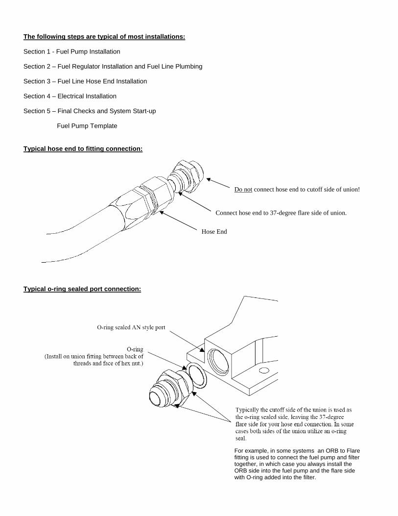
Typical hose end to fitting connection:
Typical o-ring sealed port connection:
Hose End
Connect hose end to 37-degree flare side of union.
Do not connect hose end to cutoff side of union!
For example, in some systems an ORB to Flare fitting is used to connect the fuel pump and filter together, in which case you always install the ORB side into the fuel pump and the flare side with O-ring added into the filter.
Section 1 - Fuel Pump Installation: 1-1. Once the engine has been allowed to cool, disconnect the negative battery cable and relieve the fuel system pressure. 1-2. Raise the vehicle and support it with jack stands. 1-3. Referring to the appropriate vehicle service manual for instructions, drain, disconnect any electrical and fuel
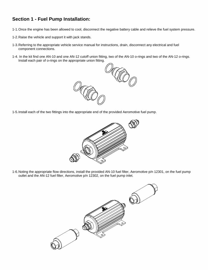
component connections. 1-4. In the kit find one AN-10 and one AN-12 cutoff union fitting, two of the AN-10 o-rings and two of the AN-12 o-rings.
Install each pair of o-rings on the appropriate union fitting.
1-5. Install each of the two fittings into the appropriate end of the provided Aeromotive fuel pump.
1-6. Noting the appropriate flow directions, install the provided AN-10 fuel filter, Aeromotive p/n 12301, on the fuel pump outlet and the AN-12 fuel filter, Aeromotive p/n 12302, on the fuel pump inlet.
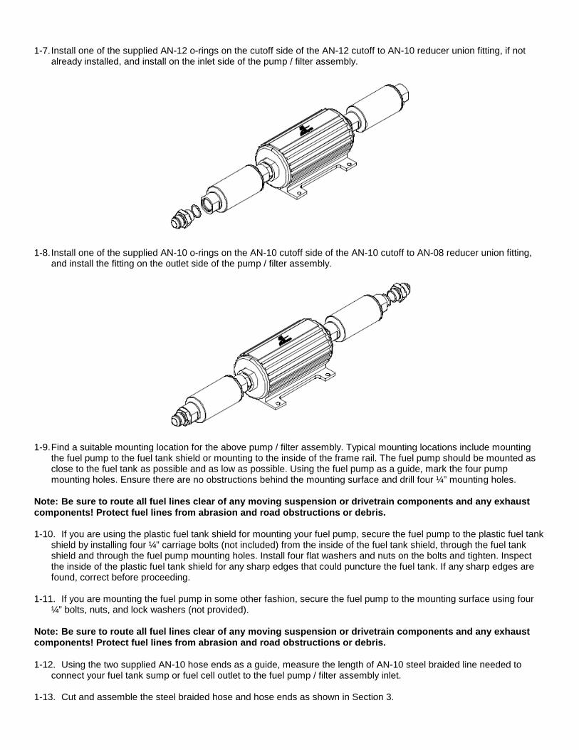
1-7. Install one of the supplied AN-12 o-rings on the cutoff side of the AN-12 cutoff to AN-10 reducer union fitting, if not
already installed, and install on the inlet side of the pump / filter assembly.
1-8. Install one of the supplied AN-10 o-rings on the AN-10 cutoff side of the AN-10 cutoff to AN-08 reducer union fitting,
and install the fitting on the outlet side of the pump / filter assembly.
1-9. Find a suitable mounting location for the above pump / filter assembly. Typical mounting locations include mounting
the fuel pump to the fuel tank shield or mounting to the inside of the frame rail. The fuel pump should be mounted as close to the fuel tank as possible and as low as possible. Using the fuel pump as a guide, mark the four pump mounting holes. Ensure there are no obstructions behind the mounting surface and drill four ¼” mounting holes.
Note: Be sure to route all fuel lines clear of any moving suspension or drivetrain components and any exhaust components! Protect fuel lines from abrasion and road obstructions or debris. 1-10. If you are using the plastic fuel tank shield for mounting your fuel pump, secure the fuel pump to the plastic fuel tank
shield by installing four ¼” carriage bolts (not included) from the inside of the fuel tank shield, through the fuel tank shield and through the fuel pump mounting holes. Install four flat washers and nuts on the bolts and tighten. Inspect the inside of the plastic fuel tank shield for any sharp edges that could puncture the fuel tank. If any sharp edges are found, correct before proceeding.
1-11. If you are mounting the fuel pump in some other fashion, secure the fuel pump to the mounting surface using four
¼” bolts, nuts, and lock washers (not provided). Note: Be sure to route all fuel lines clear of any moving suspension or drivetrain components and any exhaust components! Protect fuel lines from abrasion and road obstructions or debris. 1-12. Using the two supplied AN-10 hose ends as a guide, measure the length of AN-10 steel braided line needed to
connect your fuel tank sump or fuel cell outlet to the fuel pump / filter assembly inlet. 1-13. Cut and assemble the steel braided hose and hose ends as shown in Section 3.
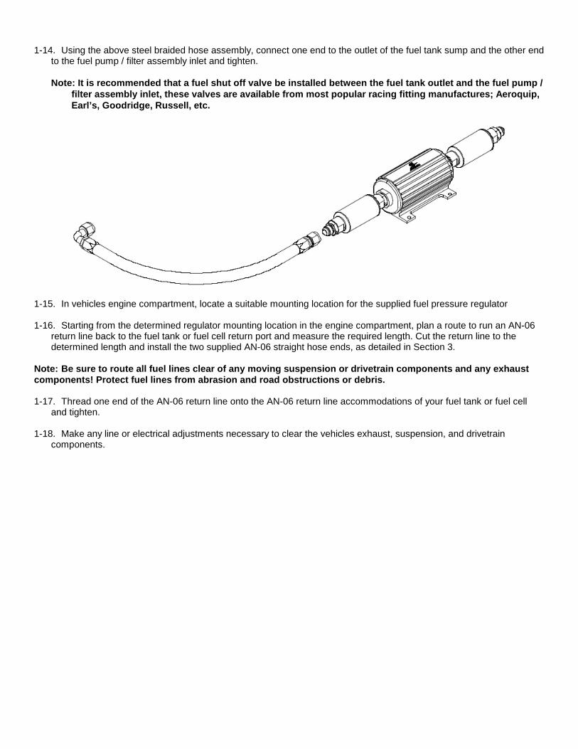
1-14. Using the above steel braided hose assembly, connect one end to the outlet of the fuel tank sump and the other end
to the fuel pump / filter assembly inlet and tighten.
Note: It is recommended that a fuel shut off valve be installed between the fuel tank outlet and the f uel pump / filter assembly inlet, these valves are available f rom most popular racing fitting manufactures; Aeroq uip, Earl’s, Goodridge, Russell, etc.
1-15. In vehicles engine compartment, locate a suitable mounting location for the supplied fuel pressure regulator 1-16. Starting from the determined regulator mounting location in the engine compartment, plan a route to run an AN-06
return line back to the fuel tank or fuel cell return port and measure the required length. Cut the return line to the determined length and install the two supplied AN-06 straight hose ends, as detailed in Section 3.
Note: Be sure to route all fuel lines clear of any moving suspension or drivetrain components and any exhaust components! Protect fuel lines from abrasion and road obstructions or debris. 1-17. Thread one end of the AN-06 return line onto the AN-06 return line accommodations of your fuel tank or fuel cell
and tighten. 1-18. Make any line or electrical adjustments necessary to clear the vehicles exhaust, suspension, and drivetrain
components.
Section 2 – Fuel Regulator Installation and Fuel Li ne Plumbing 2-1. In the vehicle’s engine compartment, mount the supplied fuel pressure regulator in the location established in step 1-
15. Using the supplied mounting bracket as a template, mark the bracket mounting holes and drill to accept a #10 screw.
2-2. With the bracket attached to the regulator, mount the bracket and regulator to the vehicle using two #10 screws, nuts
and lock washers (not provided). 2-3. Install two of the supplied AN-10 o-rings on the cutoff side of two AN-10 cutoff to AN-08 reducer union fittings, if not
already installed, and install in each of the AN-10 ports located on the sides of the supplied fuel pressure regulator.
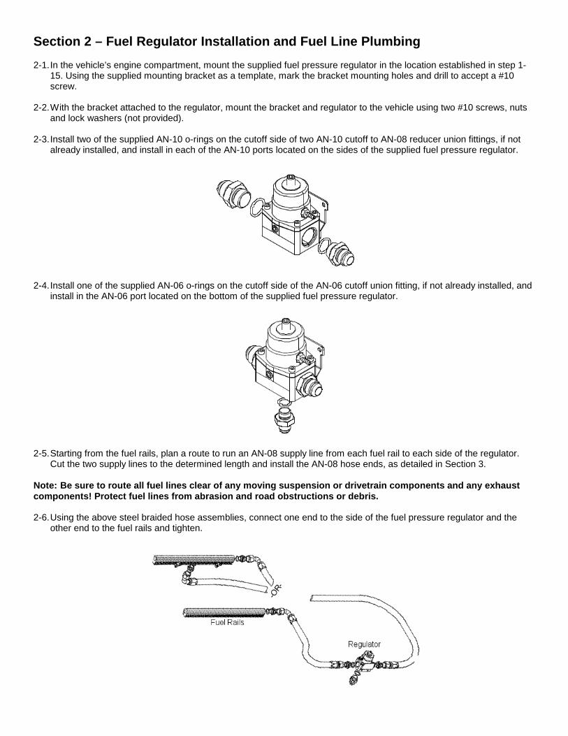
2-4. Install one of the supplied AN-06 o-rings on the cutoff side of the AN-06 cutoff union fitting, if not already installed, and install in the AN-06 port located on the bottom of the supplied fuel pressure regulator.
2-5. Starting from the fuel rails, plan a route to run an AN-08 supply line from each fuel rail to each side of the regulator.
Cut the two supply lines to the determined length and install the AN-08 hose ends, as detailed in Section 3. Note: Be sure to route all fuel lines clear of any moving suspension or drivetrain components and any exhaust components! Protect fuel lines from abrasion and road obstructions or debris. 2-6. Using the above steel braided hose assemblies, connect one end to the side of the fuel pressure regulator and the
other end to the fuel rails and tighten.
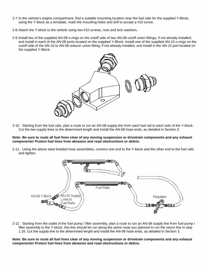
2-7. In the vehicle’s engine compartment, find a suitable mounting location near the fuel rails for the supplied Y-Block,
using the Y-block as a template, mark the mounting holes and drill to accept a #10 screw. 2-8. Attach the Y-block to the vehicle using two #10 screws, nuts and lock washers. 2-9. Install two of the supplied AN-08 o-rings on the cutoff side of two AN-08 cutoff union fittings, if not already installed,
and install in each of the AN-08 ports located on the supplied Y-Block. Install one of the supplied AN-10 o-rings on the cutoff side of the AN-10 to AN-08 reducer union fitting, if not already installed, and install in the AN-10 port located on the supplied Y-Block.
2-10. Starting from the fuel rails, plan a route to run an AN-08 supply line from each fuel rail to each side of the Y-block. Cut the two supply lines to the determined length and install the AN-08 hose ends, as detailed in Section 3.
Note: Be sure to route all fuel lines clear of any moving suspension or drivetrain components and any exhaust components! Protect fuel lines from abrasion and road obstructions or debris. 2-11. Using the above steel braided hose assemblies, connect one end to the Y-block and the other end to the fuel rails
and tighten.
2-12. Starting from the outlet of the fuel pump / filter assembly, plan a route to run an AN-08 supply line from fuel pump /
filter assembly to the Y-block, this line should be run along the same route you planned to run the return line in step 1.16. Cut the supply line to the determined length and install the AN-08 hose ends, as detailed in Section 3.
Note: Be sure to route all fuel lines clear of any moving suspension or drivetrain components and any exhaust components! Protect fuel lines from abrasion and road obstructions or debris.
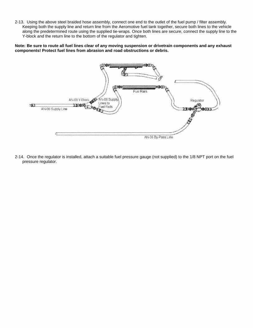
2-13. Using the above steel braided hose assembly, connect one end to the outlet of the fuel pump / filter assembly.
Keeping both the supply line and return line from the Aeromotive fuel tank together, secure both lines to the vehicle along the predetermined route using the supplied tie-wraps. Once both lines are secure, connect the supply line to the Y-block and the return line to the bottom of the regulator and tighten.
Note: Be sure to route all fuel lines clear of any moving suspension or drivetrain components and any exhaust components! Protect fuel lines from abrasion and road obstructions or debris.
2-14. Once the regulator is installed, attach a suitable fuel pressure gauge (not supplied) to the 1/8 NPT port on the fuel pressure regulator.
Section 3 - Fuel Line Hose End Installation:
CAUTION: When assembling this product, wear eye goggles and other safety apparel as needed to
protect yourself from debris and sharp edges. 3-1. Wrap hose with masking tape at desired cutoff length. Cut hose through masking tape squarely to desired length using
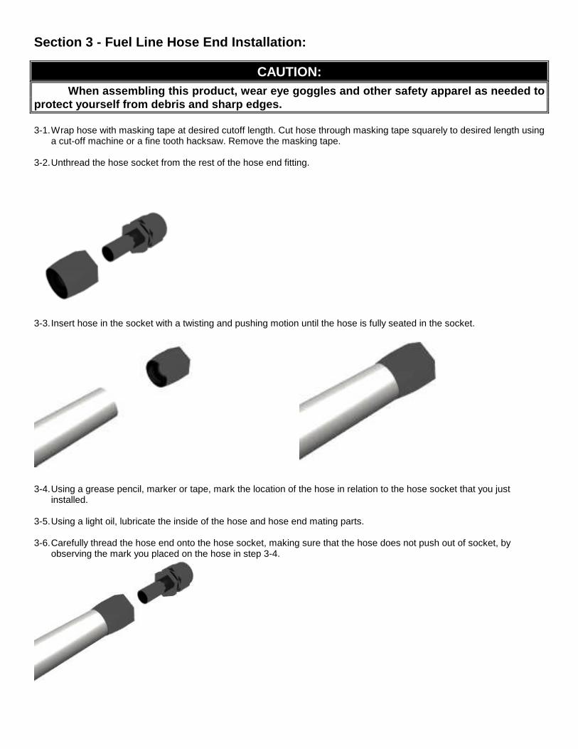
a cut-off machine or a fine tooth hacksaw. Remove the masking tape. 3-2. Unthread the hose socket from the rest of the hose end fitting.
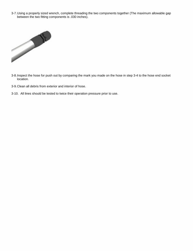
3-3. Insert hose in the socket with a twisting and pushing motion until the hose is fully seated in the socket.
3-4. Using a grease pencil, marker or tape, mark the location of the hose in relation to the hose socket that you just
installed. 3-5. Using a light oil, lubricate the inside of the hose and hose end mating parts. 3-6. Carefully thread the hose end onto the hose socket, making sure that the hose does not push out of socket, by
observing the mark you placed on the hose in step 3-4.
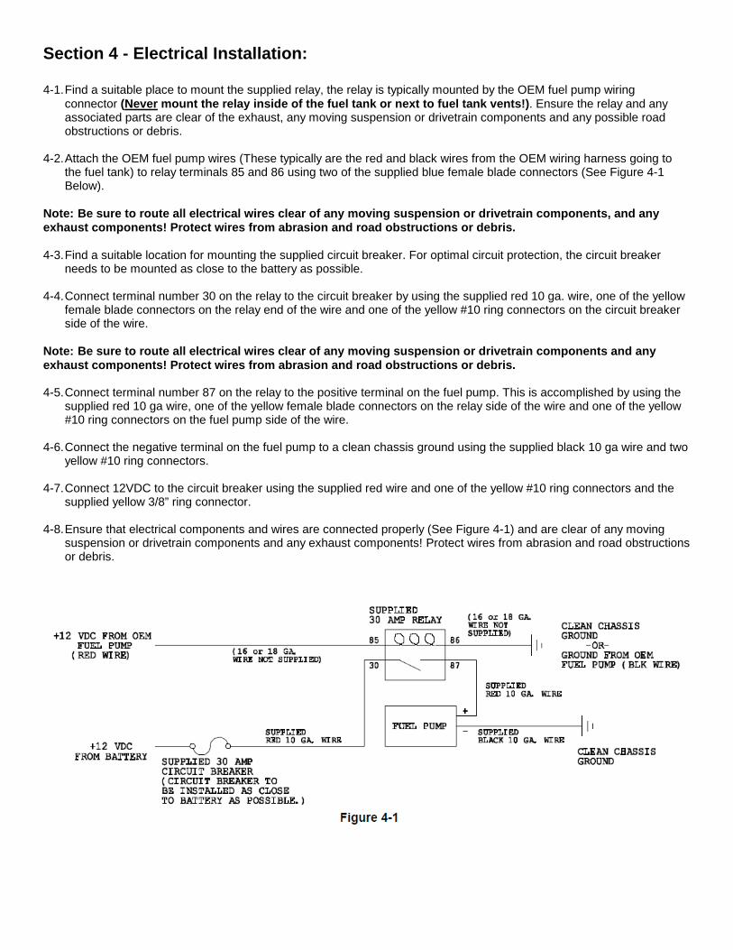
3-7. Using a properly sized wrench, complete threading the two components together (The maximum allowable gap between the two fitting components is .030 inches).
3-8. Inspect the hose for push out by comparing the mark you made on the hose in step 3-4 to the hose end socket
location. 3-9. Clean all debris from exterior and interior of hose. 3-10. All lines should be tested to twice their operation pressure prior to use.
Section 4 - Electrical Installation: 4-1. Find a suitable place to mount the supplied relay, the relay is typically mounted by the OEM fuel pump wiring
connector (Never mount the relay inside of the fuel tank or next to fuel tank vents!). Ensure the relay and any associated parts are clear of the exhaust, any moving suspension or drivetrain components and any possible road obstructions or debris.
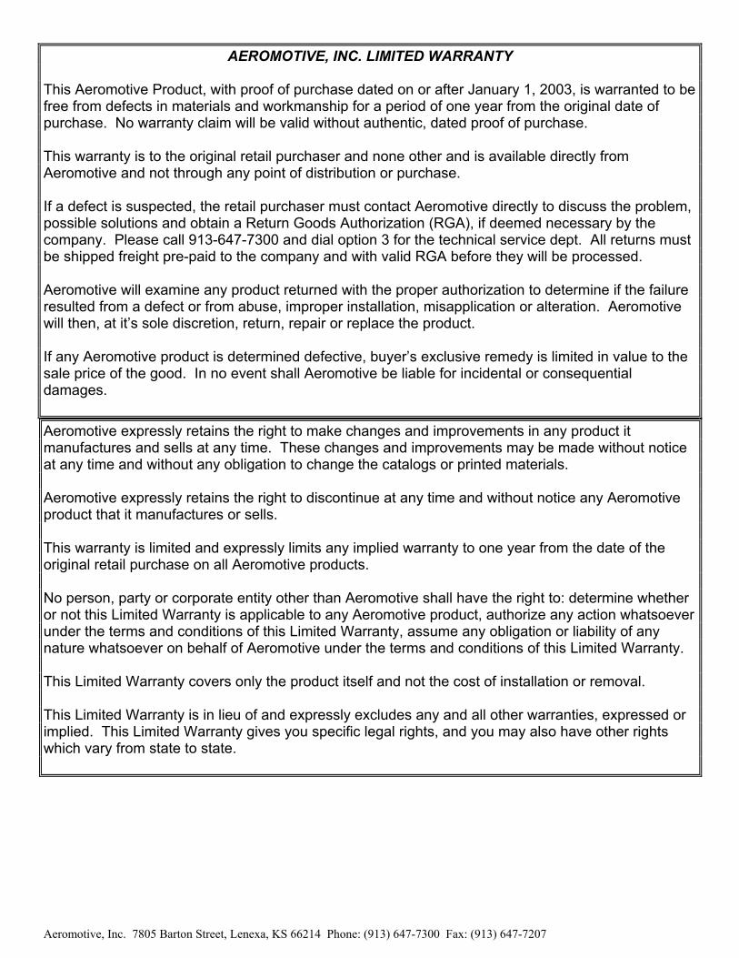
4-2. Attach the OEM fuel pump wires (These typically are the red and black wires from the OEM wiring harness going to
the fuel tank) to relay terminals 85 and 86 using two of the supplied blue female blade connectors (See Figure 4-1 Below).
Note: Be sure to route all electrical wires clear of any moving suspension or drivetrain components, and any exhaust components! Protect wires from abrasion and road obstructions or debris. 4-3. Find a suitable location for mounting the supplied circuit breaker. For optimal circuit protection, the circuit breaker
needs to be mounted as close to the battery as possible. 4-4. Connect terminal number 30 on the relay to the circuit breaker by using the supplied red 10 ga. wire, one of the yellow
female blade connectors on the relay end of the wire and one of the yellow #10 ring connectors on the circuit breaker side of the wire.
Note: Be sure to route all electrical wires clear of any moving suspension or drivetrain components and any exhaust components! Protect wires from abrasion and road obstructions or debris. 4-5. Connect terminal number 87 on the relay to the positive terminal on the fuel pump. This is accomplished by using the
supplied red 10 ga wire, one of the yellow female blade connectors on the relay side of the wire and one of the yellow #10 ring connectors on the fuel pump side of the wire.
4-6. Connect the negative terminal on the fuel pump to a clean chassis ground using the supplied black 10 ga wire and two
yellow #10 ring connectors. 4-7. Connect 12VDC to the circuit breaker using the supplied red wire and one of the yellow #10 ring connectors and the
supplied yellow 3/8” ring connector. 4-8. Ensure that electrical components and wires are connected properly (See Figure 4-1) and are clear of any moving
suspension or drivetrain components and any exhaust components! Protect wires from abrasion and road obstructions or debris.

AEROMOTIVE, INC. 7805 Barton Street, Lenexa, KS 66214
913-647-7300 fax 913-647-7207 www.aeromotiveinc.com
Section 5 – Final Checks and System Start-up 5-1. Ensure that any spilled gasoline and any gasoline s oaked shop towels are cleaned up and removed from t he
vicinity of the vehicle! 5-2. Carefully lower the car onto the ground. 5-3. Fill the fuel tank with gasoline and check for any leaks in the system, if any leaks are found repair immediately. CAUTION: While performing the following steps, if any fuel l eaks are detected, immediately turn the ignition OFF, remove any spilled fuel and repair the leak(s) before proceeding! 5-4. Reconnect the battery and turn the ignition to the ON position WITHOUT starting the car. After several seconds, check
the fuel pressure. If there is no fuel pressure, turn the ignition key to the OFF position, wait one minute, return the ignition to the ON position, and recheck the fuel pressure. Repeat this ignition OFF and ON procedure until the fuel pressure gauge registers fuel pressure.
5-5. With the fuel pressure gauge registering fuel system pressure, check for fuel leaks throughout th e entire fuel
system! If any fuel leaks are found, turn the ignit ion key to the OFF position, remove any spilled fue l and repair the leak before proceeding!
5-6. Once the fuel pressure gauge registers fuel system pressure and there are no fuel leaks, start the engine and adjust
the regulator to the desired fuel pressure. Turning the adjustment screw clockwise will increase fuel pressure. OEM regulators are typically set at approximately 43 psi, without the vacuum line attached. The fuel pressure adjustment range for this regulator is 35-80 psi.
5-7. Once the desired fuel pressure is achieved, tighten the regulator adjustment jam nut and attach the vacuum line. 5-8. Test drive the car to ensure proper operation and re-check the fuel system for leaks. If any leaks are found,
immediately discontinue use of the vehicle and repa ir the leak(s)!
Aeromotive, Inc. 7805 Barton Street, Lenexa, KS 66214 Phone: (913) 647-7300 Fax: (913) 647-7207
AEROMOTIVE, INC. LIMITED WARRANTY This Aeromotive Product, with proof of purchase dated on or after January 1, 2003, is warranted to be free from defects in materials and workmanship for a period of one year from the original date of purchase. No warranty claim will be valid without authentic, dated proof of purchase. This warranty is to the original retail purchaser and none other and is available directly from Aeromotive and not through any point of distribution or purchase. If a defect is suspected, the retail purchaser must contact Aeromotive directly to discuss the problem, possible solutions and obtain a Return Goods Authorization (RGA), if deemed necessary by the company. Please call 913-647-7300 and dial option 3 for the technical service dept. All returns must be shipped freight pre-paid to the company and with valid RGA before they will be processed. Aeromotive will examine any product returned with the proper authorization to determine if the failure resulted from a defect or from abuse, improper installation, misapplication or alteration. Aeromotive will then, at it’s sole discretion, return, repair or replace the product. If any Aeromotive product is determined defective, buyer’s exclusive remedy is limited in value to the sale price of the good. In no event shall Aeromotive be liable for incidental or consequential damages.
Aeromotive expressly retains the right to make changes and improvements in any product it manufactures and sells at any time. These changes and improvements may be made without notice at any time and without any obligation to change the catalogs or printed materials. Aeromotive expressly retains the right to discontinue at any time and without notice any Aeromotive product that it manufactures or sells. This warranty is limited and expressly limits any implied warranty to one year from the date of the original retail purchase on all Aeromotive products. No person, party or corporate entity other than Aeromotive shall have the right to: determine whether or not this Limited Warranty is applicable to any Aeromotive product, authorize any action whatsoever under the terms and conditions of this Limited Warranty, assume any obligation or liability of any nature whatsoever on behalf of Aeromotive under the terms and conditions of this Limited Warranty. This Limited Warranty covers only the product itself and not the cost of installation or removal. This Limited Warranty is in lieu of and expressly excludes any and all other warranties, expressed or implied. This Limited Warranty gives you specific legal rights, and you may also have other rights which vary from state to state.