advanced settings for custom...
TRANSCRIPT
Operating Instructions
Advanced Settings for Custom Paper
For safe and correct use, be sure to read Safety Information before usingthe machine.

TABLE OF CONTENTS1. Introduction
Basic Procedure.................................................................................................................................................. 3
Advanced Settings..............................................................................................................................................4
2. Printing Process
Overview.............................................................................................................................................................5
Laser Exposure....................................................................................................................................................7
Laser Unit (Exposure)..................................................................................................................................... 7
Development....................................................................................................................................................... 8
Development...................................................................................................................................................8
Drum-to-Belt Transfer....................................................................................................................................... 10
Drum-to-Belt Transfer...................................................................................................................................10
Belt-to-Paper Transfer...................................................................................................................................... 11
Belt-to-Paper Transfer..................................................................................................................................11
PTR Rotation Speed......................................................................................................................................13
Fusing................................................................................................................................................................ 14
Fusing Unit.................................................................................................................................................... 14
Fusing Nip Width Adjustment..................................................................................................................... 15
Fusing Cleaning Unit....................................................................................................................................15
Fusing Belt Smoothing Roller.......................................................................................................................16
Paper Delivery.................................................................................................................................................. 18
Mainframe....................................................................................................................................................18
Decurl Unit....................................................................................................................................................21
Vacuum Feed LCIT....................................................................................................................................... 22
3. Details of Advanced Settings
Overview.......................................................................................................................................................... 25
Print Mode....................................................................................................................................................25
Registration....................................................................................................................................................... 26
Image Position/Magnification....................................................................................................................26
Image Quality...................................................................................................................................................27
Maximum Image Density............................................................................................................................ 27
Drum-to-belt Transfer Current..................................................................................................................... 27
Belt-to-paper Transfer..................................................................................................................................28
Fusing............................................................................................................................................................30
1

Paper Feed/Delivery....................................................................................................................................... 35
Main Tray/Vacuum Feed LCIT...................................................................................................................35
Adjusting the Machine’s Paper Delivery and Output............................................................................... 40
2
1. IntroductionThis chapter provides an overview of the Media Library.
Basic ProcedureProC9200/C9210 Series is capable of printing on a wide variety of media using the latesttechnologies in digital printing such as the AC transfer and elastic fusing belt.
In addition to these technologies, support of various media is also made possible by the Media Librarydatabase, which is registered with tested and proved media and programmed with optimized printparameters by media type/weight.
How to use the Media Library:
1. Select a media from the library and associate the media to a tray.
2. Set the media on the associated tray.
3. Specify the media in Job Properties of the color controller.
3
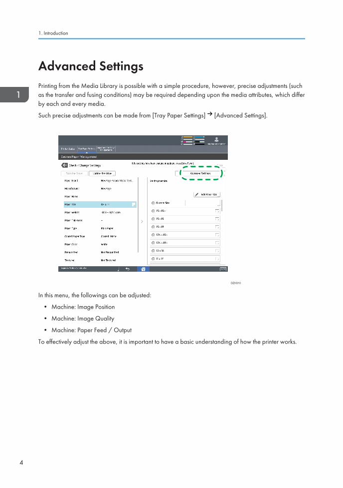
Advanced SettingsPrinting from the Media Library is possible with a simple procedure, however, precise adjustments (suchas the transfer and fusing conditions) may be required depending upon the media attributes, which differby each and every media.
Such precise adjustments can be made from [Tray Paper Settings] [Advanced Settings].
DZH310
In this menu, the followings can be adjusted:
• Machine: Image Position
• Machine: Image Quality
• Machine: Paper Feed / Output
To effectively adjust the above, it is important to have a basic understanding of how the printer works.
1. Introduction
4
2. Printing ProcessThis chapter provides explanation on the basic Xerographic process of the engine by referring to theitems of the Advanced Settings.
Overview
Y M C K
DZH300
122
34
5
76
8
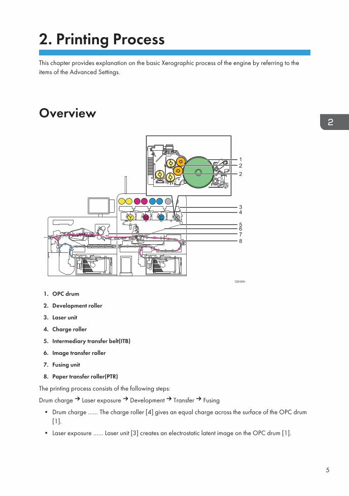
1. OPC drum
2. Development roller
3. Laser unit
4. Charge roller
5. Intermediary transfer belt(ITB)
6. Image transfer roller
7. Fusing unit
8. Paper transfer roller(PTR)
The printing process consists of the following steps:
Drum charge Laser exposure Development Transfer Fusing
• Drum charge …… The charge roller [4] gives an equal charge across the surface of the OPC drum[1].
• Laser exposure …… Laser unit [3] creates an electrostatic latent image on the OPC drum [1].
5

• Development …… The development roller [2] carries toner to the latent image on the OPC drum[1].
• Image transfer
Drum-to-belt transfer …… Toner images created on each OPC drum [1] are transferred sequentiallyto the ITB [5].
Belt-to-paper transfer …… Toner image on the ITB [5] is transferred onto the paper when the paperpasses through the PTR [8].
• Fusing …… The fusing unit [7] applies heat and pressure to fuse the toner image onto the paper.
2. Printing Process
6
Laser Exposure
Laser Unit (Exposure)
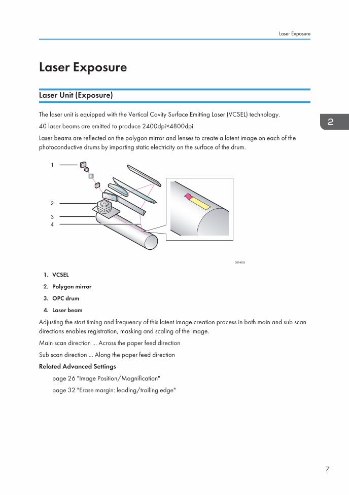
The laser unit is equipped with the Vertical Cavity Surface Emitting Laser (VCSEL) technology.
40 laser beams are emitted to produce 2400dpi×4800dpi.
Laser beams are reflected on the polygon mirror and lenses to create a latent image on each of thephotoconductive drums by imparting static electricity on the surface of the drum.
1
2
3 4
DZH003
1. VCSEL
2. Polygon mirror
3. OPC drum
4. Laser beam
Adjusting the start timing and frequency of this latent image creation process in both main and sub scandirections enables registration, masking and scaling of the image.
Main scan direction ... Across the paper feed direction
Sub scan direction ... Along the paper feed direction
Related Advanced Settings
page 26 "Image Position/Magnification"
page 32 "Erase margin: leading/trailing edge"
Laser Exposure
7
Development
Development
The development system employs the dual-component*1 development method.
The developer is pre-mixed*2 to prevent image quality degradation caused by deterioration of thedeveloper that occurs over time.
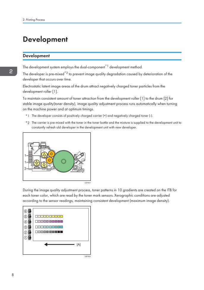
Electrostatic latent image areas of the drum attract negatively charged toner particles from thedevelopment roller [1].
To maintain consistent amount of toner attraction from the development roller [1] to the drum [2] forstable image quality(toner density), image quality adjustment process runs automatically when turningon the machine power and at optimum timings.
*1 The developer consists of positively charged carrier (+) and negatively charged toner (-).
*2 The carrier is pre-mixed with the toner in the toner bottle and the mixture is supplied to the development unit toconstantly refresh old developer in the development unit with new developer.
1
2
1
DZH301
During the image quality adjustment process, toner patterns in 10 gradients are created on the ITB foreach toner color, which are read by the toner mark sensors. Xerographic conditions are adjustedaccording to the sensor readings, maintaining consistent development (maximum image density).
[A]
6
5
4
3
2
1
DZH302
2. Printing Process
8

Related Advanced Settings
page 27 "Maximum Image Density"
Development
9
Drum-to-Belt Transfer
Drum-to-Belt Transfer
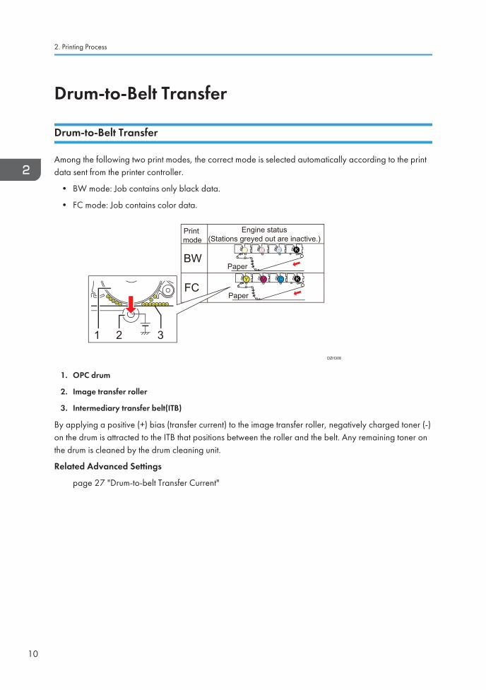
Among the following two print modes, the correct mode is selected automatically according to the printdata sent from the printer controller.
• BW mode: Job contains only black data.
• FC mode: Job contains color data.
1 2 3
BW
FC
Print mode
Engine status(Stations greyed out are inactive.)
Paper
Paper
Y M C
Y M C
K
K
DZH308
1. OPC drum
2. Image transfer roller
3. Intermediary transfer belt(ITB)
By applying a positive (+) bias (transfer current) to the image transfer roller, negatively charged toner (-)on the drum is attracted to the ITB that positions between the roller and the belt. Any remaining toner onthe drum is cleaned by the drum cleaning unit.
Related Advanced Settings
page 27 "Drum-to-belt Transfer Current"
2. Printing Process
10
Belt-to-Paper Transfer
Belt-to-Paper Transfer
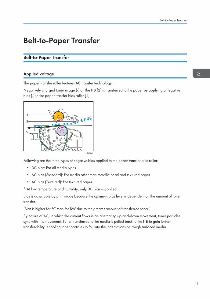
Applied voltage
The paper transfer roller features AC transfer technology.
Negatively charged toner image (-) on the ITB [2] is transferred to the paper by applying a negativebias (-) to the paper transfer bias roller [1].
DZH307
1
2
Following are the three types of negative bias applied to the paper transfer bias roller:
• DC bias: For all media types
• AC bias (Standard): For media other than metallic pearl and textured paper
• AC bias (Textured): For textured paper
* At low temperature and humidity, only DC bias is applied.
Bias is adjustable by print mode because the optimum bias level is dependent on the amount of tonertransfer.
(Bias is higher for FC than for BW due to the greater amount of transferred toner.)
By nature of AC, in which the current flows in an alternating up-and-down movement, toner particlessync with this movement. Toner transferred to the media is pulled back to the ITB to gain furthertransferability, enabling toner particles to fall into the indentations on rough surfaced media.
Belt-to-Paper Transfer
11
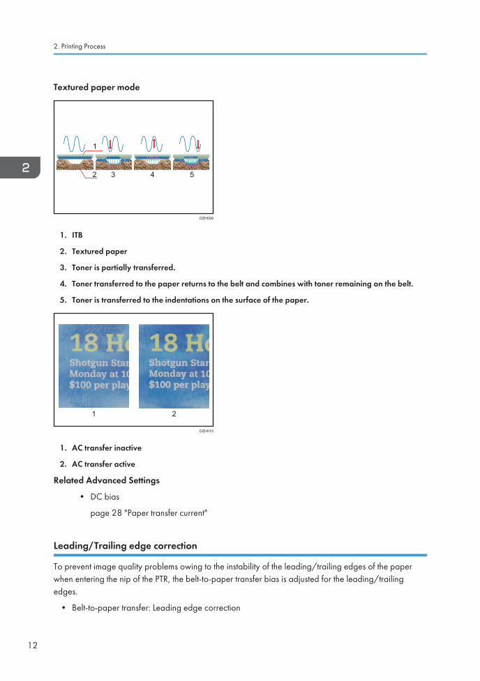
Textured paper mode
1
2 3 4 5
DZH009
1. ITB
2. Textured paper
3. Toner is partially transferred.
4. Toner transferred to the paper returns to the belt and combines with toner remaining on the belt.
5. Toner is transferred to the indentations on the surface of the paper.
DZH010
1 2
1. AC transfer inactive
2. AC transfer active
Related Advanced Settings
• DC bias
page 28 "Paper transfer current"
Leading/Trailing edge correction
To prevent image quality problems owing to the instability of the leading/trailing edges of the paperwhen entering the nip of the PTR, the belt-to-paper transfer bias is adjusted for the leading/trailingedges.
• Belt-to-paper transfer: Leading edge correction
2. Printing Process
12
• Belt-to-paper transfer: Trailing edge correction
• Belt-to-paper transfer: Length of area to apply correction at leading edge of paper
• Belt-to-paper transfer: Length of area to apply correction at trailing edge of paper
• Current vs. Voltage
• Bias is applied using 'constant current' for drum-to-belt and belt-to-paper transfer, as thismethod is resilient to changes in operational environment and thickness of the media.
• On the other hand, 'constant voltage' is used for AC bias and as this method does not requireadjustments according to paper width.
Related Advanced Settings
page 29 "Belt-to-paper transfer correction: LE/TE"
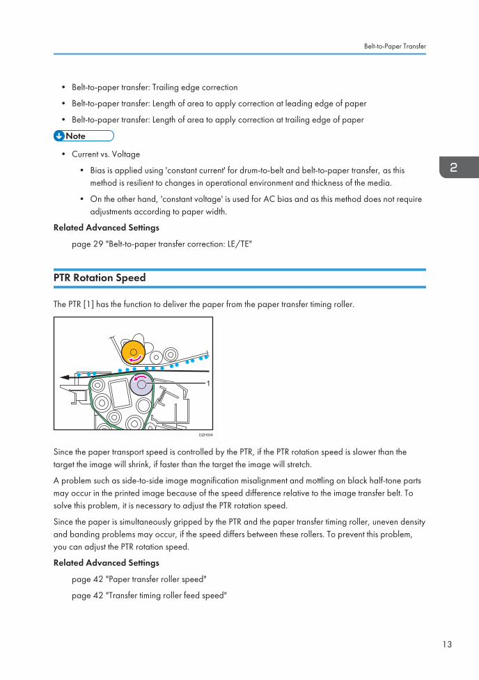
PTR Rotation Speed
The PTR [1] has the function to deliver the paper from the paper transfer timing roller.
DZH304
1
Since the paper transport speed is controlled by the PTR, if the PTR rotation speed is slower than thetarget the image will shrink, if faster than the target the image will stretch.
A problem such as side-to-side image magnification misalignment and mottling on black half-tone partsmay occur in the printed image because of the speed difference relative to the image transfer belt. Tosolve this problem, it is necessary to adjust the PTR rotation speed.
Since the paper is simultaneously gripped by the PTR and the paper transfer timing roller, uneven densityand banding problems may occur, if the speed differs between these rollers. To prevent this problem,you can adjust the PTR rotation speed.
Related Advanced Settings
page 42 "Paper transfer roller speed"
page 42 "Transfer timing roller feed speed"
Belt-to-Paper Transfer
13
Fusing
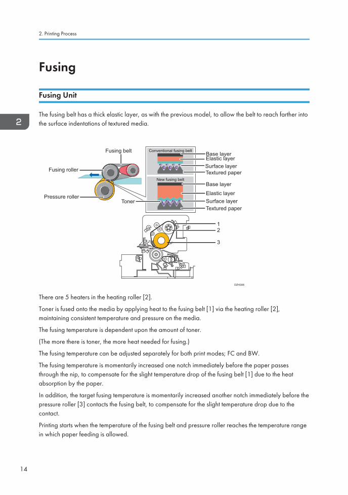
Fusing Unit
The fusing belt has a thick elastic layer, as with the previous model, to allow the belt to reach farther intothe surface indentations of textured media.
Base layer
Base layer
Elastic layer
Elastic layer
Surface layer
Surface layer
Textured paper
Textured paper
Fusing belt
Toner
Conventional fusing belt
New fusing belt
12
3
DZH306
Fusing roller
Pressure roller
There are 5 heaters in the heating roller [2].
Toner is fused onto the media by applying heat to the fusing belt [1] via the heating roller [2],maintaining consistent temperature and pressure on the media.
The fusing temperature is dependent upon the amount of toner.
(The more there is toner, the more heat needed for fusing.)
The fusing temperature can be adjusted separately for both print modes; FC and BW.
The fusing temperature is momentarily increased one notch immediately before the paper passesthrough the nip, to compensate for the slight temperature drop of the fusing belt [1] due to the heatabsorption by the paper.
In addition, the target fusing temperature is momentarily increased another notch immediately before thepressure roller [3] contacts the fusing belt, to compensate for the slight temperature drop due to thecontact.
Printing starts when the temperature of the fusing belt and pressure roller reaches the temperature rangein which paper feeding is allowed.
2. Printing Process
14
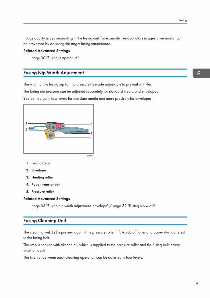
Image quality issues originating in the fusing unit, for example, residual gloss images, river marks, canbe prevented by adjusting the target fusing temperature.
Related Advanced Settings
page 30 "Fusing temperature"
Fusing Nip Width Adjustment
The width of the fusing nip (or nip pressure) is made adjustable to prevent wrinkles.
The fusing nip pressure can be adjusted separately for standard media and envelopes.
You can adjust in four levels for standard media and more precisely for envelopes.
DZH013
1 3
45
2
1. Fusing roller
2. Envelope
3. Heating roller
4. Paper transfer belt
5. Pressure roller
Related Advanced Settings
page 33 "Fusing nip width adjustment: envelope" / page 32 "Fusing nip width"
Fusing Cleaning Unit
The cleaning web [2] is pressed against the pressure roller [1], to rub off toner and paper dust adheredto the fusing belt.
The web is soaked with silicone oil, which is supplied to the pressure roller and the fusing belt in verysmall amounts.
The interval between each cleaning operation can be adjusted in four levels.
Fusing
15
12
DZH322
Related Advanced Settings
page 31 "Fusing cleaning web"
Fusing Belt Smoothing Roller
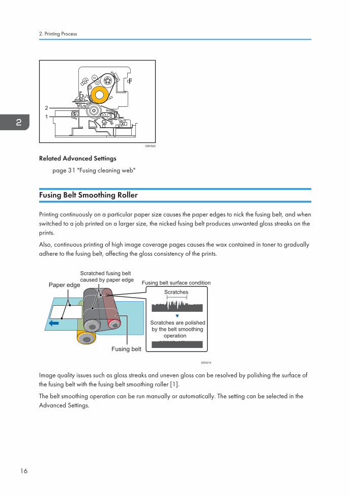
Printing continuously on a particular paper size causes the paper edges to nick the fusing belt, and whenswitched to a job printed on a larger size, the nicked fusing belt produces unwanted gloss streaks on theprints.
Also, continuous printing of high image coverage pages causes the wax contained in toner to graduallyadhere to the fusing belt, affecting the gloss consistency of the prints.
Paper edge
Scratched fusing belt caused by paper edge
Fusing belt
Fusing belt surface condition
Scratches
Scratches are polished by the belt smoothing operation
DZH214
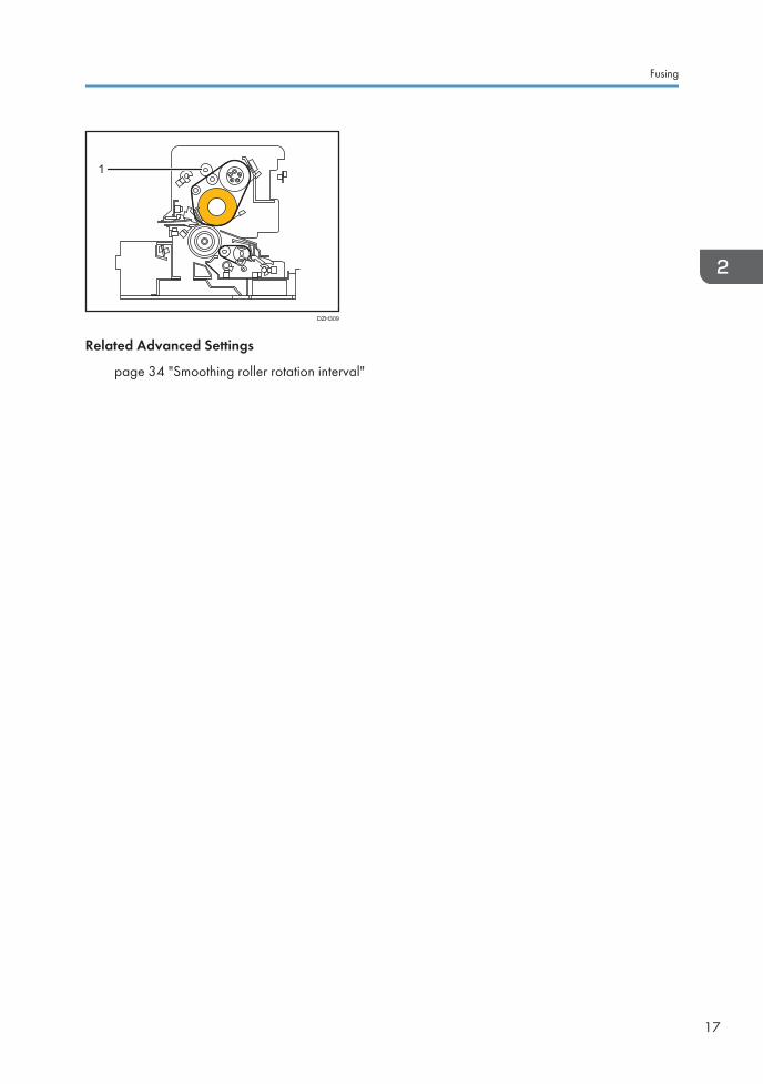
Image quality issues such as gloss streaks and uneven gloss can be resolved by polishing the surface ofthe fusing belt with the fusing belt smoothing roller [1].
The belt smoothing operation can be run manually or automatically. The setting can be selected in theAdvanced Settings.
2. Printing Process
16
1
DZH309
Related Advanced Settings
page 34 "Smoothing roller rotation interval"
Fusing
17
Paper Delivery
Mainframe
The paper feed/delivery system consists of various technologies to meet high front-to-back registrationrequirements demanded in the commercial printing market. The paper fed from the tray is first checkedfor double-feed and is then adjusted of skew and main/sub scan registration before the belt-to-papertransfer process.
Skew detection & main scan registration
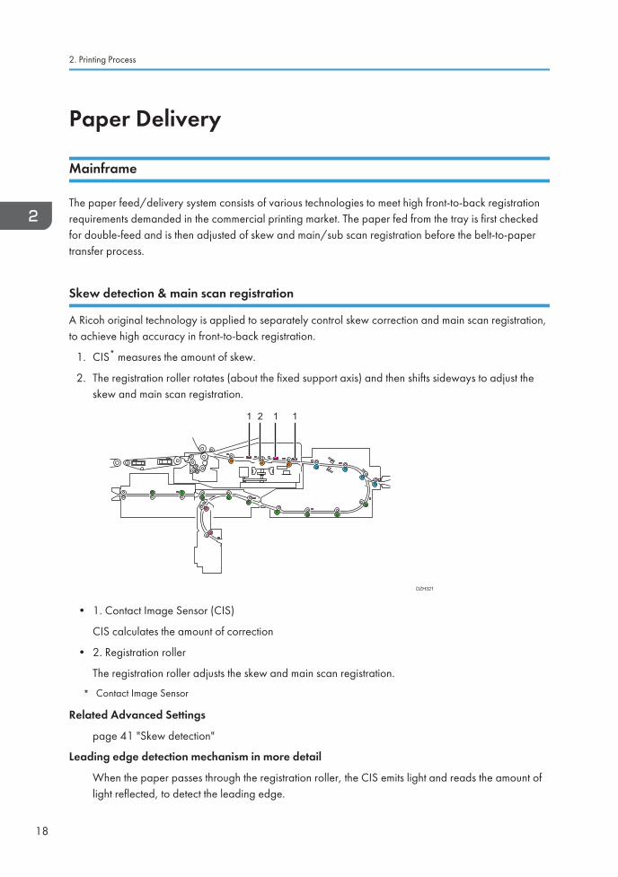
A Ricoh original technology is applied to separately control skew correction and main scan registration,to achieve high accuracy in front-to-back registration.
1. CIS* measures the amount of skew.
2. The registration roller rotates (about the fixed support axis) and then shifts sideways to adjust theskew and main scan registration.
DZH321
1 2 1 1
• 1. Contact Image Sensor (CIS)
CIS calculates the amount of correction
• 2. Registration roller
The registration roller adjusts the skew and main scan registration.
* Contact Image Sensor
Related Advanced Settings
page 41 "Skew detection"
Leading edge detection mechanism in more detail
When the paper passes through the registration roller, the CIS emits light and reads the amount oflight reflected, to detect the leading edge.
2. Printing Process
18
The sensor reading is 0V when there is no reflection (no paper detected) whereas a certain voltageis detected when there is reflection.
High voltage is detected when the reflection is high; white paper, whereas low voltage is detectedwhen the reflection is low; dark/black paper.
The CIS mode and its light intensity are set according to the color of the media (color, black).
However, low voltage from low reflection may occasionally be falsely detected as jams. In suchcase, increase the light intensity.
Related Advanced Settings
page 41 "Paper edge detection"
Double-feed detection mechanism
Double-feed detection prevents unwanted blank sheets from mixing in the job to minimize inspectiontime for high productivity.
Double-feeds are detected by reading the difference in the ultrasonic wave lengths between one sheetand two or more sheets. The function also works for colored media and transparencies.
When detected, the machine alerts jam code J099.
Related Advanced Settings
page 40 "Double feed detection"
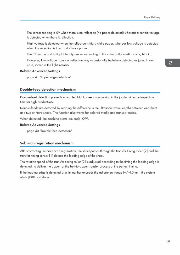
Sub scan registration mechanism
After correcting the main scan registration, the sheet passes through the transfer timing roller [2] and thetransfer timing sensor [1] detects the leading edge of the sheet.
The rotation speed of the transfer timing roller [2] is adjusted according to the timing the leading edge isdetected, to deliver the paper for the belt-to-paper transfer process at the perfect timing.
If the leading edge is detected at a timing that exceeds the adjustment range (+/-4.0mm), the systemalerts J080 and stops.
Paper Delivery
19
DZH312
21
Related Advanced Settings
page 40 "J080 detection"
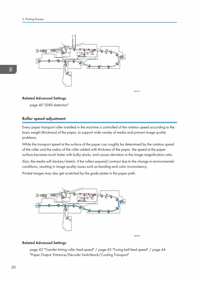
Roller speed adjustment
Every paper transport roller installed in the machine is controlled of the rotation speed according to thebasis weight (thickness) of the paper, to support wide variety of media and prevent image qualityproblems.
While the transport speed at the surface of the paper can roughly be determined by the rotation speedof the roller and the radius of the roller added with thickness of the paper, the speed at the papersurface becomes much faster with bulky stocks, and causes deviation in the image magnification ratio.
Also, the media will slacken/stretch, if the rollers expand/contract due to the change in environmentalconditions, resulting in image quality issues such as banding and color inconsistency.
Printed images may also get scratched by the guide plates in the paper path.
DZH320
Related Advanced Settings
page 42 "Transfer timing roller feed speed" / page 43 "Fusing belt feed speed" / page 44"Paper Output: Entrance/Decurler Switchback/Cooling Transport"
2. Printing Process
20
Decurl Unit
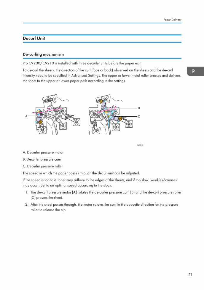
De-curling mechanism
Pro C9200/C9210 is installed with three decurler units before the paper exit.
To de-curl the sheets, the direction of the curl (face or back) observed on the sheets and the de-curlintensity need to be specified in Advanced Settings. The upper or lower metal roller presses and deliversthe sheet to the upper or lower paper path according to the settings.
DZH318
A
B
C
A. Decurler pressure motor
B. Decurler pressure cam
C. Decurler pressure roller
The speed in which the paper passes through the decurl unit can be adjusted.
If the speed is too fast, toner may adhere to the edges of the sheets, and if too slow, wrinkles/creasesmay occur. Set to an optimal speed according to the stock.
1. The de-curl pressure motor [A] rotates the de-curler pressure cam [B] and the de-curl pressure roller[C] presses the sheet.
2. After the sheet passes through, the motor rotates the cam in the opposite direction for the pressureroller to release the nip.
Paper Delivery
21
1 2
DZH319
A
B
C
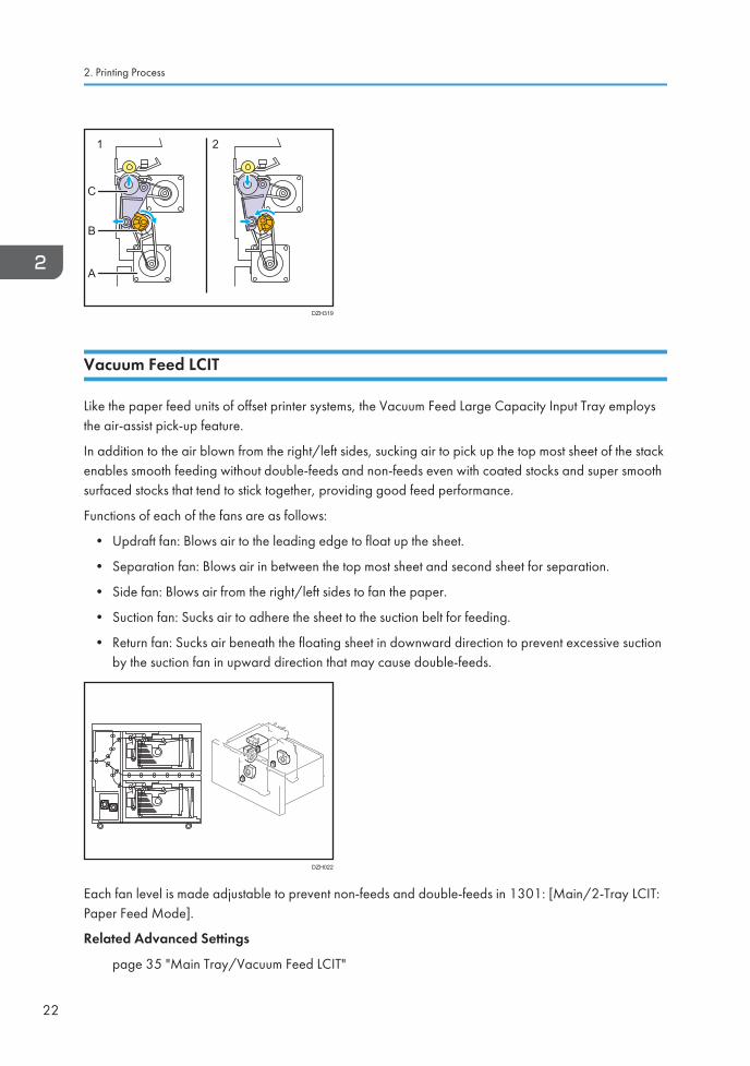
Vacuum Feed LCIT
Like the paper feed units of offset printer systems, the Vacuum Feed Large Capacity Input Tray employsthe air-assist pick-up feature.
In addition to the air blown from the right/left sides, sucking air to pick up the top most sheet of the stackenables smooth feeding without double-feeds and non-feeds even with coated stocks and super smoothsurfaced stocks that tend to stick together, providing good feed performance.
Functions of each of the fans are as follows:
• Updraft fan: Blows air to the leading edge to float up the sheet.
• Separation fan: Blows air in between the top most sheet and second sheet for separation.
• Side fan: Blows air from the right/left sides to fan the paper.
• Suction fan: Sucks air to adhere the sheet to the suction belt for feeding.
• Return fan: Sucks air beneath the floating sheet in downward direction to prevent excessive suctionby the suction fan in upward direction that may cause double-feeds.
DZH022
Each fan level is made adjustable to prevent non-feeds and double-feeds in 1301: [Main/2-Tray LCIT:Paper Feed Mode].
Related Advanced Settings
page 35 "Main Tray/Vacuum Feed LCIT"
2. Printing Process
22
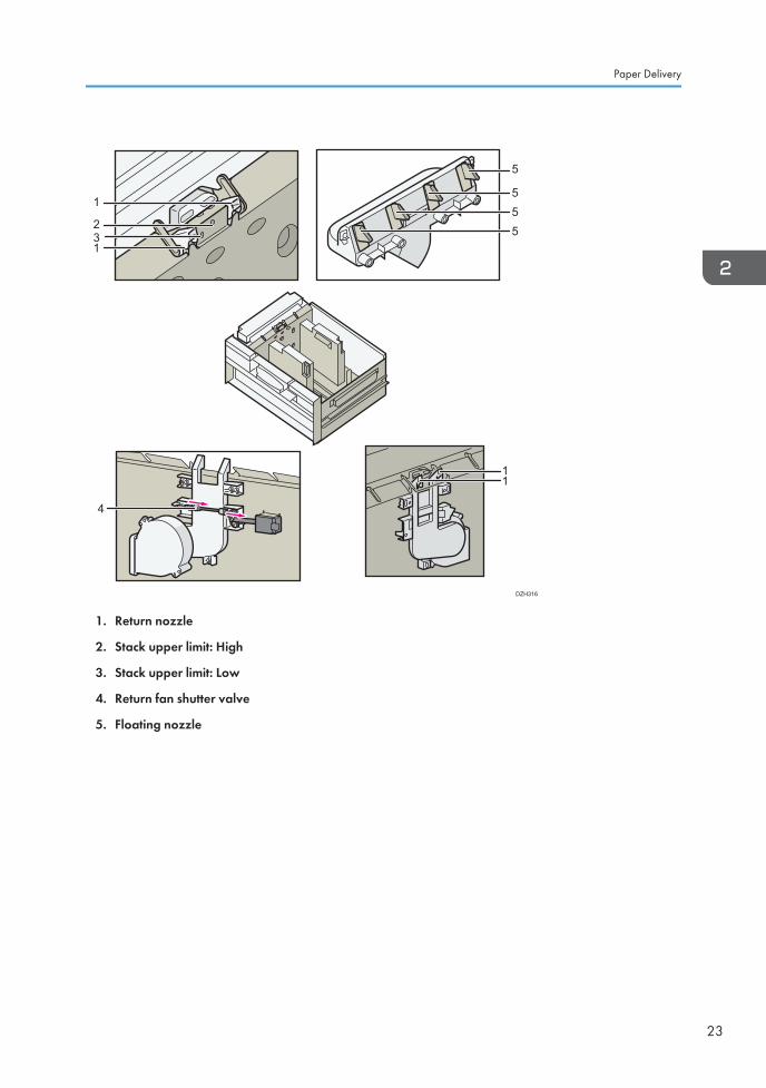
32
1
1
11
4
555
5
DZH316
1. Return nozzle
2. Stack upper limit: High
3. Stack upper limit: Low
4. Return fan shutter valve
5. Floating nozzle
Paper Delivery
23

2. Printing Process
24
3. Details of Advanced SettingsThis chapter explains the functions of the Advanced Settings and the related image quality problems thatcan be prevented/improved by adjusting these settings. For detailed procedure, see theTroubleshooting manual.
Overview
Print Mode
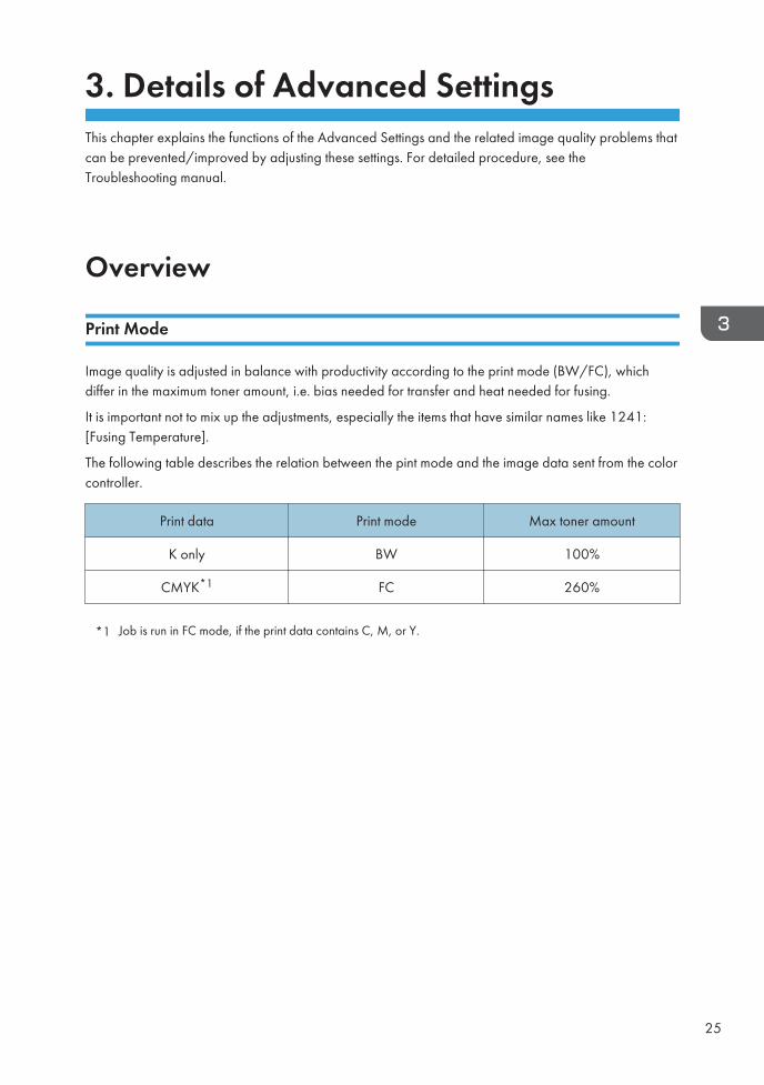
Image quality is adjusted in balance with productivity according to the print mode (BW/FC), whichdiffer in the maximum toner amount, i.e. bias needed for transfer and heat needed for fusing.
It is important not to mix up the adjustments, especially the items that have similar names like 1241:[Fusing Temperature].
The following table describes the relation between the pint mode and the image data sent from the colorcontroller.
Print data Print mode Max toner amount
K only BW 100%
CMYK*1 FC 260%
*1 Job is run in FC mode, if the print data contains C, M, or Y.
25
Registration
Image Position/Magnification
1101 [Image Position]
1102 [Auto Adjust Image Position]
1103 [Image Position Feedback Correction]
1104 [Image Position Feedback Correction: Gap]
Function
Adjusts the position and magnification of the image to be printed on the paper.
When to use
• To align the images printed on the front and back sides of the paper.
Insufficient margin at the leading edge may cause wrap around jams in the fusing unit oraffect the images at the leading edge. Increasing the margin is effective in such cases.
• To switch the sensor to be used between plain paper printing and special paper printing, suchas printing on colored paper and transparencies.
Related Troubleshooting
• Adjusting the Image Position on Side1
• Adjusting the Image Position on Side2
• Horizontal Streaks at the Area within 20 mm (0.8 inches) from the Leading Edge
• Aligning the Image Position on Side 2 to That on Side 1 (Using a Template to Align the ImagePosition on Side 1 and 2)
• Other Paper Delivery Problems
For detailed procedure, see the Troubleshooting manual.
3. Details of Advanced Settings
26
Image Quality
Maximum Image Density
1201 [Max Image Density]
Function
Adjusts the amount of toner developed on the drum.
When to use
To adjust the maximum toner density for the media in use.
Note the possible side effects, such as worm track and toner scattering, if set too high.
Related Troubleshooting
• Color Dots: Textured Paper
• Low Image Density
• White Spots on a Textured Surface
For detailed procedure, see the Troubleshooting manual.
Drum-to-belt Transfer Current
1212 [Image Transfer Output]
Function
Adjusts the amount of bias applied for the drum-to-belt transfer process.
Effective for:
• Mottling effect that may occur when continuously printing low image coverage pages
• Negative residual image that may appear when running jobs in low room temperature
• Toner scattering that may appear when printed on coated or smooth surfaced media
Related Troubleshooting
• Horizontal Streaks at the Area within 20 mm (0.8 inches) from the Leading Edge
• Low Image Density
• White Spots: Scaly
• Toner Scattering: Trailing Edge
For detailed procedure, see the Troubleshooting manual.
Image Quality
27
Drum-to-belt transfer correction
1215 [Image Transfer Output Correction]
Function
Corrects the amount of transfer current applied to the drum-to-belt transfer process.
Effective for:
If white spots appear, decrease this value.
If the leading edge shows density problems or scattered toner or streaks appearing across the feeddirection, increase this value.
If toner is scattered close to the trailing edge, increase this value.
If the job is printed in FC and black appears low in density, increase this value.
Related Troubleshooting
None
Belt-to-paper Transfer
Paper transfer current
1214 [Paper Transfer Output]
Function
Adjusts the amount of bias applied for the belt-to-paper transfer process.
Effective for:
• White spots/Toner blasting that may occur in low humidity/temp environment
• Mottling effect
Related Troubleshooting
• Low Image Density
• Faint Image: Oval
• White Spots/Toner Blasting
• Mottling
• Mottling: Half-Tone Parts
• Horizontal White Streaks around the Edge of the Paper
• Color Dots: Textured Paper
• White Spots on a Textured Surface
• Density Fluctuation in Black: Cork-Shaped
• Fingerprints appear
3. Details of Advanced Settings
28
For detailed procedure, see the Troubleshooting manual.
Belt-to-paper transfer correction: LE/TE
1217 [Paper Transfer Output Correction: Paper Edge]
Function
Adjusts the amount and area (width) of the bias applied at the leading/trailing edges for the belt-to-paper transfer process.
When to use
• Image is affected/abnormal at the trailing edge.
Related Troubleshooting
• Density Fluctuation at the Leading Edge (When Using Thick Paper)
• Density Fluctuation at the Trailing Edge (When Using Thick Paper)
• Faint Image around the Leading Edge
• Toner Scattering: Trailing Edge
For detailed procedure, see the Troubleshooting manual.
Paper transfer gap
1227 [Paper Transfer Nip Operation Mode]
1228 [Paper Transfer Nip]
Function
Adjusts the gap between the PTR and ITB and the timing of when to contact/separate the PTR andITB.
Default setting of 1227: [Paper Transfer Nip Operation Mode] by type/thickness:
1. OFF: Thick 1 - 2, envelope, transparency, plastic folder, magnet sheet
2. Small gap: Thick 3 - 5 (excluding envelope, transparency), Thick 6 - 8 (including coated,metallic/pearl)
3. Large gap: (Not used)
4. Small/Large gap: Thick 6 - 8 (excluding coated, metallic/pearl)
When to use
Image is affected/abnormal at the trailing edge
Related Troubleshooting
None
Image Quality
29
Belt-to-paper transfer nip pressure
1229 [Paper Transfer Pressure]
Function
Adjusts the nip pressure between the paper transfer roller and the bias roller in four levels (1-4).Select a higher number as the surface of the media gets rougher.
Effective for:
• Inaccurate image magnification rate along feed direction
• Mottled effect, faint images, image degradation at the leading/trailing edges
Related Troubleshooting
• Horizontal Streaks: When Using Thick Paper (3)
• Horizontal Streaks at the Area within 20 mm (0.8 inches) from the Leading Edge
• Color Dots: Textured Paper
• Uneven Density within 127 mm (5 inches) from the Trailing Edge
• White Spots on a Textured Surface
• Mottling: Half-Tone Parts
• Misregistered image magnification
For detailed procedure, see the Troubleshooting manual.
Fusing
Fusing temperature
1241 [Fusing Temperature]
Function
Adjusts the temperature of the fusing belt.
Effective for:
Poor fusing, residual gloss image (ghosting), uneven gloss, fusing jam (J036).
Related Troubleshooting
• Improving Fusibility
• Black (color) Spots (2)
• Uneven Gloss
• Uneven Gloss: Wavy
• Uneven Gloss: Orange Peel
• Paper Edges are Stained
3. Details of Advanced Settings
30
• Creases, Worm Track (Wavy Streaks), or Bends Appear
• If (J086) Appears
• Reducing the Waiting Time Prior to Printing
• Improving Throughput when Continuously Printing on Paper of Different Types or Thicknesses
• Excessive or Uneven Glossiness
For detailed procedure, see the Troubleshooting manual.
Fusing pressure roller contact before job
1242 [Fusing Pressure Roller On Before Fusing]
Function
The pressure roller comes into contact with the fusing belt before the job starts, so that the pressureroller is well heated in advance. With the pressure roller heated, toner particles that adhere to thepressure roller during the job will melt and become more easily removable by the cleaning web.
Effective for:
Small black spots, images affected by toner adhesion to the pressure roller separation plate
Related Troubleshooting
• Black (color) Spots (2)
For detailed procedure, see the Troubleshooting manual.
Fusing pressure roller contact after job
1243 [Fusing Pressure Roller On After Fusing]
Function
The pressure roller comes into contact with the fusing belt after the job completes, to heat thepressure roller. With the pressure roller heated, toner particles that adhered to the pressure rollerduring the job will melt and become more easily removable by the cleaning web.
When to use
This setting basically does not require any adjustments.
Related Troubleshooting
None
Fusing cleaning web
1244 [Fusing Cleaning Web]
Image Quality
31
Function
Specifies the interval of the web cleaning operation and the behavior of the pressure roller when itseparates from the fusing belt.
Effective for:
Black spots
Related Troubleshooting
• Black (color) Spots (2)
For detailed procedure, see the Troubleshooting manual.
Erase margin: leading/trailing edge
1245 [Erase Margin]
Function
Adjusts the width of the margins at the leading and trailing edges.
When to use
An insufficient margin at the leading edge may cause wraparound jams in the fusing unit or affectthe images at the leading edge of uncoated paper or coated thin paper.
Related Troubleshooting
• If (J038) Appears
• Other Paper Delivery Problems
• Shortening the Leading/Trailing Edge Margins
• Aligning the Image Position on Side 2 to That on Side 1 (Using a Template to Align the ImagePosition on Side 1 and 2)
For detailed procedure, see the Troubleshooting manual.
Fusing nip width
1246 [Fusing Nip Width Adjustment] 01:[ Other than Envelope]
Function
Adjusts the nip width for plain paper.
When to use
If stains appear on the edges of stacked sheets when printed on plain paper, or wrinkles occurwhen printed thin paper, adjust this setting.
Related Troubleshooting
None
3. Details of Advanced Settings
32
Fusing nip width adjustment: envelope
1246 [Fusing Nip Width Adjustment] 02: [Envelope]
Function
Specifies the fusing nip width specifically for envelope printing.
When to use
Effective for wrinkles, worm track that occur with envelope.
Related Troubleshooting
• Creases, Worm Track (Wavy Streaks), or Bends Appear
• Wrong Detection of Skew
• Paper Misfeeding
• Jam code J122 appears when envelopes are delivered
• Aligning the Image Position on Side 2 to That on Side 1 (Using a Template to Align the ImagePosition on Side 1 and 2)
• Envelopes
For detailed procedure, see the Troubleshooting manual.
Fusing temperature range
1247 [Fusing Temperature Range]
Function
Specifies the fusing temperature range that permits paper feeding. Setting a large range enablesquick job start, but with the risk of poor fusing.
When to use
Waiting time is too long, for example, when the job is printed on thin paper or is a mixed mediajob.
Related Troubleshooting
• Improving Throughput when Continuously Printing on Paper of Different Types or Thicknesses
For detailed procedure, see the Troubleshooting manual.
Fusing pressure roller cooling
1248 [Fusing Pressure Roller Cooling]
Function
Set the cooling fan level of pressure roller.
Image Quality
33
When to use
This setting basically does not require any adjustments.
Related Troubleshooting
None
Smoothing roller rotation interval
1249 [Fusing Belt Smoothing]
Function
Specifies the fusing belt smoothing roller operation interval.
When to use
Setting a shorter interval between each belt smoothing operation is effective for residual glossimages (as shown to right), which occurs as a result of continuous printing of high image coveragepages (due to the margins at the trailing and leading edges).
This is also effective in preventing or ameliorating wrinkling at the edges.
Related Troubleshooting
• Glossy Lines at the Edge of the Paper
For detailed procedure, see the Troubleshooting manual.
Print mode when switching paper type
1250 [Print Mode When Switching Paper Type]
Function
Specifies the waiting time before the feed tray switches for mixed media job. Selecting [ProductivityPriority] will shorten the waiting time, but may cause poor fusing.
When to use
Use this when precise balance between productivity and image quality needs to be adjusted inmixed media jobs in which tray switching time is unavoidable.
Related Troubleshooting
None
3. Details of Advanced Settings
34
Paper Feed/Delivery
Main Tray/Vacuum Feed LCIT
Main/2-Tray LCIT: paper feed mode
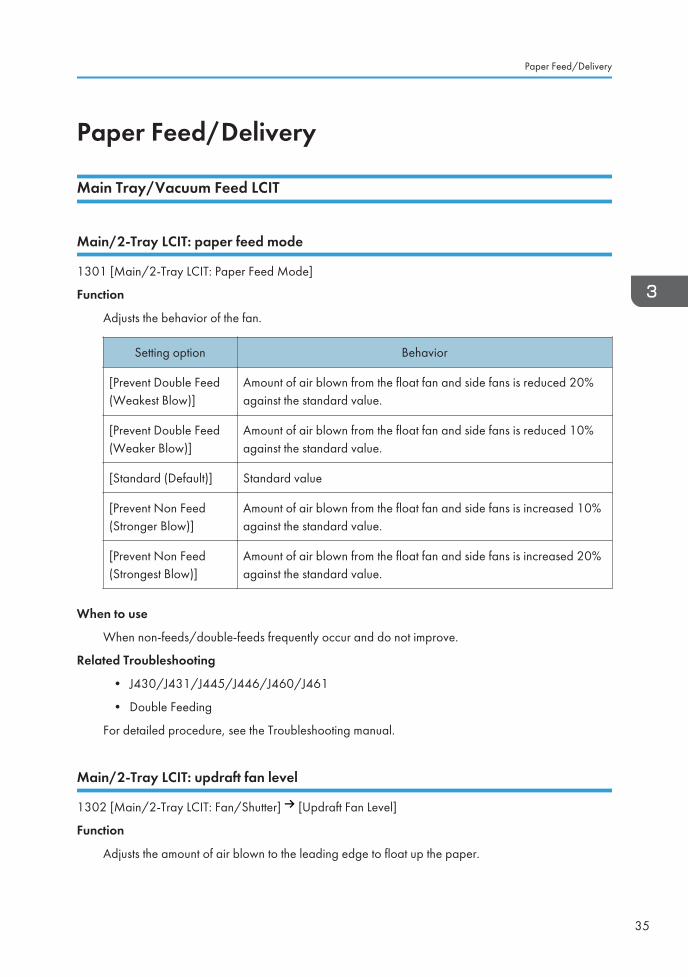
1301 [Main/2-Tray LCIT: Paper Feed Mode]
Function
Adjusts the behavior of the fan.
Setting option Behavior
[Prevent Double Feed(Weakest Blow)]
Amount of air blown from the float fan and side fans is reduced 20%against the standard value.
[Prevent Double Feed(Weaker Blow)]
Amount of air blown from the float fan and side fans is reduced 10%against the standard value.
[Standard (Default)] Standard value
[Prevent Non Feed(Stronger Blow)]
Amount of air blown from the float fan and side fans is increased 10%against the standard value.
[Prevent Non Feed(Strongest Blow)]
Amount of air blown from the float fan and side fans is increased 20%against the standard value.
When to use
When non-feeds/double-feeds frequently occur and do not improve.
Related Troubleshooting
• J430/J431/J445/J446/J460/J461
• Double Feeding
For detailed procedure, see the Troubleshooting manual.
Main/2-Tray LCIT: updraft fan level
1302 [Main/2-Tray LCIT: Fan/Shutter] [Updraft Fan Level]
Function
Adjusts the amount of air blown to the leading edge to float up the paper.
Paper Feed/Delivery
35
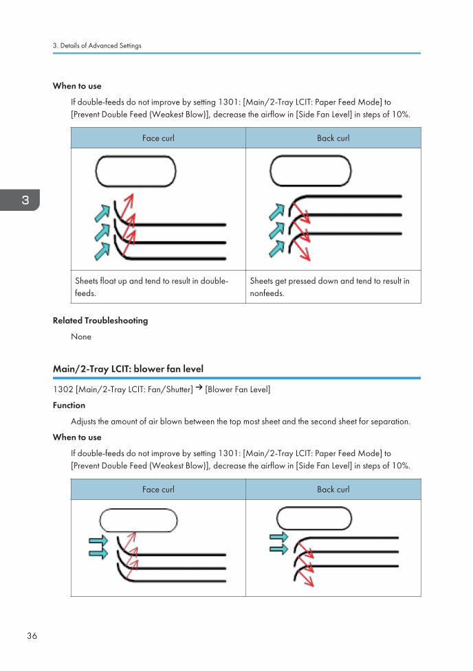
When to use
If double-feeds do not improve by setting 1301: [Main/2-Tray LCIT: Paper Feed Mode] to[Prevent Double Feed (Weakest Blow)], decrease the airflow in [Side Fan Level] in steps of 10%.
Face curl Back curl
Sheets float up and tend to result in double-feeds.
Sheets get pressed down and tend to result innonfeeds.
Related Troubleshooting
None
Main/2-Tray LCIT: blower fan level
1302 [Main/2-Tray LCIT: Fan/Shutter] [Blower Fan Level]
Function
Adjusts the amount of air blown between the top most sheet and the second sheet for separation.
When to use
If double-feeds do not improve by setting 1301: [Main/2-Tray LCIT: Paper Feed Mode] to[Prevent Double Feed (Weakest Blow)], decrease the airflow in [Side Fan Level] in steps of 10%.
Face curl Back curl
3. Details of Advanced Settings
36
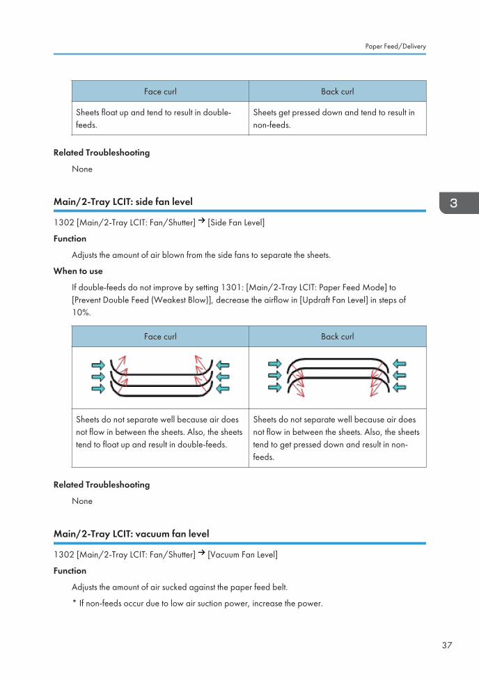
Face curl Back curl
Sheets float up and tend to result in double-feeds.
Sheets get pressed down and tend to result innon-feeds.
Related Troubleshooting
None
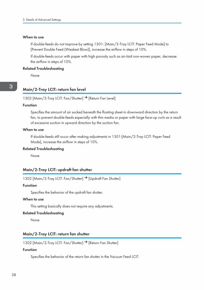
Main/2-Tray LCIT: side fan level
1302 [Main/2-Tray LCIT: Fan/Shutter] [Side Fan Level]
Function
Adjusts the amount of air blown from the side fans to separate the sheets.
When to use
If double-feeds do not improve by setting 1301: [Main/2-Tray LCIT: Paper Feed Mode] to[Prevent Double Feed (Weakest Blow)], decrease the airflow in [Updraft Fan Level] in steps of10%.
Face curl Back curl
Sheets do not separate well because air doesnot flow in between the sheets. Also, the sheetstend to float up and result in double-feeds.
Sheets do not separate well because air doesnot flow in between the sheets. Also, the sheetstend to get pressed down and result in non-feeds.
Related Troubleshooting
None
Main/2-Tray LCIT: vacuum fan level
1302 [Main/2-Tray LCIT: Fan/Shutter] [Vacuum Fan Level]
Function
Adjusts the amount of air sucked against the paper feed belt.
* If non-feeds occur due to low air suction power, increase the power.
Paper Feed/Delivery
37
When to use
If double-feeds do not improve by setting 1301: [Main/2-Tray LCIT: Paper Feed Mode] to[Prevent Double Feed (Weakest Blow)], increase the airflow in steps of 10%.
If double-feeds occur with paper with high porosity such as air-laid non-woven paper, decreasethe airflow in steps of 10%.
Related Troubleshooting
None
Main/2-Tray LCIT: return fan level
1302 [Main/2-Tray LCIT: Fan/Shutter] [Return Fan Level]
Function
Specifies the amount of air sucked beneath the floating sheet in downward direction by the returnfan, to prevent double-feeds especially with thin media or paper with large face-up curls as a resultof excessive suction in upward direction by the suction fan.
When to use
If double-feeds still occur after making adjustments in 1301:[Main/2-Tray LCIT: Paper FeedMode], increase the airflow in steps of 10%.
Related Troubleshooting
None
Main/2-Tray LCIT: updraft fan shutter
1302 [Main/2-Tray LCIT: Fan/Shutter] [Updraft Fan Shutter]
Function
Specifies the behavior of the updraft fan shutter.
When to use
This setting basically does not require any adjustments.
Related Troubleshooting
None
Main/2-Tray LCIT: return fan shutter
1302 [Main/2-Tray LCIT: Fan/Shutter] [Return Fan Shutter]
Function
Specifies the behavior of the return fan shutter in the Vacuum Feed LCIT.
3. Details of Advanced Settings
38
If set to On, the shutter opens and closes per sheet.
If set to Off, the shutter remains open.
When to use
This setting basically does not require any adjustments.
Related Troubleshooting
None
Main/2-Tray LCIT: vacuum fan shutter
1302 [Main/2-Tray LCIT: Fan/Shutter] [Vacuum Fan Shutter]
Function
Specifies the behavior of the vacuum fan shutter.
If set to On, the shutter opens and closes per sheet.
If set to Off, the shutter remains open.
When to use
This setting basically does not require any adjustments.
Related Troubleshooting
None
Main/2-Tray LCIT: other setting
1303 [Main/2-Tray LCIT: Other Setting]
Function
Specifies the waiting time after the first sheet of the job floats up until it becomes stable and readyfor feed.
When to use
If misfeeds occur at the start of the job, specify a shorter time by decreasing the value.
If double-feeds occur at the start of the job, specify a longer time by increasing the value.
Related Troubleshooting
None
Paper Feed/Delivery
39
Adjusting the Machine’s Paper Delivery and Output
Adjust Paper Curl
1311 [Correct Paper Curl]
Function
Specifies the amount of airflow from the fans to de-curl face-up or face-down curled stocks whenfeeding.
When to use
Use this when the sock is observed with curls and causes jams or dog-ear folds or poor stacking. Itis also effective in preventing the sheets from curling after they are printed.
Related Troubleshooting
None
Double feed detection
1321 [Jam Detection] 01: [Detect JAM099]
Function
Specifies whether or not to detect double-feeds.
When to use
Set to Off, if double-feed is falsely detected frequently. Note that double-feeds will not bedetected, if set to OFF.
Related Troubleshooting
• Envelopes
For detailed procedure, see the Troubleshooting manual.
J080 detection
1321 [Jam Detection] 03: [Detect JAM080]
Function
Specifies whether or not to stop printing, if registration in sub scan direction (along feed direction)
exceeds the adjustable range (+/-4mm).
When to use
Set to Off, if jam J080 occurs frequently.
If set to Off, printing will continue with the registration in feed direction corrected up to 4mm, but nomore than 4mm.
3. Details of Advanced Settings
40
Related Troubleshooting
• If (J097) Appears
• If (J098) Appears
• Wrong Detection of Skew
• Preprinted Paper
For detailed procedure, see the Troubleshooting manual.
Skew detection
1321 [Jam Detection] 02: [JAM097/098 Detect Threshold]
1321 [Jam Detection] 05: [JAM097]
1321 [Jam Detection] 04: [JAM098]
Function
Specifies whether or not to automatically detect paper skew.
When to use
Deactivate this setting, if J097/J098 occurs frequently. However, do so only after confirming thatadjusting 1321-06: [Setting] does not resolve the jam.
Related Troubleshooting
• If (J097) Appears
• If (J098) Appears
• Wrong Detection of Skew
• Preprinted Paper
For detailed procedure, see the Troubleshooting manual.
Paper edge detection
1321 [Jam Detection] 06: [Setting]
Function
Sets the duration the light is emitted from the CIS (contact image sensor) to detect the paper edgefor color media.
When to use
Use this if excessive (JAM97/JAM98) skew/shifting occurs frequently. When printing on highlyreflective paper such as thick color paper, a (JAM97/JAM98) paper jam may be erroneouslydetected. In such a situation, it is necessary to make adjustments such as increasing luminance.
Paper Feed/Delivery
41
Also, if CIS luminance is high, paper dust and stains may accumulate in the machine, and this maycause erroneous (JAM97/JAM98) jam detection. When printing on plain and thin color paper, itmay be effective to adjust the luminance to standard value "3".
Related Troubleshooting
None
Transfer timing roller feed speed
1331 [Motor Speed] [Speed Adjustment] 01: [Transfer Timing Roller]
Function
Adjusts the transfer timing roller speed.
When to use
To troubleshoot problems caused by difference in the rotation speed against the PTR.
Related Troubleshooting
• Horizontal White Streaks around the Edge of the Paper
• Uneven Density within 127 mm (5 inches) from the Trailing Edge
• Mottling: Half-Tone Parts
• Misregistered image magnification
• Values for Adjusting [Paper Transfer Roller] and [Transfer Timing Roller]
For detailed procedure, see the Troubleshooting manual.
Paper transfer roller speed
1331 [Motor Speed] [Speed Adjustment] 02: [Paper Transfer Roller]
Function
Adjusts the paper transfer roller speed.
When to use
If a problem such as side-to-side image magnification misalignment and mottling on black half-toneparts occurs in the printed image because of the speed difference relative to the image transferbelt, the problem may be solved by adjusting the line speed.
Related Troubleshooting
• Horizontal White Streaks around the Edge of the Paper
• Uneven Density within 127 mm (5 inches) from the Trailing Edge
• Mottling: Half-Tone Parts
• Misregistered image magnification
• Values for Adjusting [Paper Transfer Roller] and [Transfer Timing Roller]
3. Details of Advanced Settings
42
For detailed procedure, see the Troubleshooting manual.
Fusing belt feed speed
1331 [Motor Speed] [Speed Adjustment] 03: [Trans-Fusing Transf Belt 1]
1331 [Motor Speed] [Speed Adjustment] 04: [Trans-Fusing Transf Belt 2]
1331 [Motor Speed] [Speed Adjustment] 05: [Fusing Belt]
Function
Adjusts the rotation speed of the fusing belt.
When to use
Slow fusing speed causes the sheets to slacken before entering the fusing nip and scatter the tonerimage. In such case, increase the fusing belt rotation speed.
For banner printing, decrease the belt rotation speed by 0.5%.
Related Troubleshooting
• Glossy Lines at the Edge of the Paper
• Uneven Gloss: Foggy
• Shortening the Leading/Trailing Edge Margins
For detailed procedure, see the Troubleshooting manual.
Process Speed Setting
1331 [Motor Speed] [Speed Adjustment] 06: [Process Speed Setting]
Function
Adjusts the speed of all the motors related to paper transport.
When to use
Insufficient fusing, wrinkles on thin paper, image quality degradation.
Related Troubleshooting
• Improving Fusibility
• Horizontal Streaks: When Using Thick Paper (1)
• Uneven Gloss
• Creases, Worm Track (Wavy Streaks), or Bends Appear
• If (J086) Appears
• Delivered Sheets Are Not Stacked Properly
For detailed procedure, see the Troubleshooting manual.
Paper Feed/Delivery
43
Paper Feed Interval Setting
1331 [Motor Speed] [Speed Adjustment] 07: [Paper Feed Interval Setting]
Function
Adjusts the speed of all the motors related to paper transport.
When to use
Clots of toner (black spots) appear on the printouts
Related Troubleshooting
• Horizontal Streaks: When Using Thick Paper (1)
• Black (color) Spots (2)
For detailed procedure, see the Troubleshooting manual.
Paper Output: Entrance/Decurler Switchback/Cooling Transport
1331 [Motor Speed] [Speed Adjustment] 08: [Paper Output: Entrance]
1331 [Motor Speed] [Speed Adjustment] 09: [Decurler Switchback]
1331 [Motor Speed] [Speed Adjustment] 10: [Cooling Transport]
Function
Adjusts the motor speed of the above units.
When to use
Paper transport speed is inconsistent among the roller, causings the paper to bend and the guideplate(s) to scratch the fused image.
Related Troubleshooting
• Oblique Wavy Streaks
For detailed procedure, see the Troubleshooting manual.
Adjust paper curl (Fusing)
1341 [Adjust Paper Curl (Fusing)]
Function
Reduces the difference in the temperatures between the fusing belt and the pressure roller so thatboth sides of the sheets are heated evenly when passing through the nip.
When to use
Printouts are curled.
Related Troubleshooting
None
3. Details of Advanced Settings
44 EN GB EN US EN AU M0B2-1031


EN GB EN US EN AU M0B2-1031 © 2018