advanced metering infrastructure - energy · advanced metering infrastructure minimum ami...
TRANSCRIPT
ADVANCED METERING INFRASTRUCTURE
Minimum AMI unctionality Specification (Victoria)
September 2008
Release 1.1
DOCUMENT CONTROL, 1 1,1 Version Control" , ",,.,,,.,,,,.,,,,.,, 1 1,2 Citation,. ,.",. 1 1,3 Approva!.", , ,,.,.,.,.,,.,,.,.,, 1
2 INTRODUCTION,,.,.,.,.,.,,.,. "'H"H,,.,,.HH,.,,,,,,,,2 2,1 BackgroundH ,.,.H HH,.H'H' 'HHH,.H'HH'H , 2 22 Purpose of Document ,.H ,.HHH 2 2,3 Scope of applicationH" HH HH,.H,.'HH,.H,.,. HH ,.H,.H HH,.H,.H 2
3 MINIMUM FUNCTIONALITY REQUIREMENTS, ,,.,3 3,1 Applicable meter configurations H" ,. HH,.HH'HH ' 'HH,.H,.HHH 'H 3 3,2 Metrology,.,. HH,.HH'H,.H HH'HH,.H,.H ' , HH,.HH,.H' HHH,,.HHH,.H 3 3,3 Remote and local reading of metersH ,. ,.,. ,., H' 4 3,4 Supply Disconnect and Reconnect H' H ,.H,,.H HHHH,.,,.'H' ,,.H 4
3.4.1 General Requirements,., 'H'HHHHH ,.H,.H,.'H ' H,. 4 3.4.2 DisconnecLHH,.H,.,.,.H H,.H'H,.H'HH'H,.H,.H H,.,.,,.HHH' ,,.,. 4 3,4,3 Reconnection HHH,.,.,.H,.,.,.,.H,.H' 'H,.H ,.H 'HH,.,.HH' HH,.H,,.H,.,. 5
3,5 Time Clock SynchronisationH ,.,.H,.H,.'HH,,.,.H,.H,.'H,.H 6 3,6 Load Control ,.H,.HHHHHHHH,.'H,.,.H,,.HH,.H"H,.,HH'H ,.,.,. 6
3,6,1 Load control Groups ,,.H,.'HH'H,,.H'H,.HH ,.H,.H,.H,.H,.,. 6 3,6,2 Controlled load management at meters HH,.H' , HH H,.'H,. 'H,.H'H,.,., ,6 3,6,3 Utility Control of Other Load,.H,.HHHHH,.HHH,H ,.H,.'H,.HHH' H,.H,,.H,,.HHH' 7 3,6.4 Random Load Control Switching Delay H,,.H'H H'HH'H'HH,7
3,1 Meter Loss of Supply detection and outage detection, ,. HH'HH' ,8 3,8 Quality of Supply & other event recording ,,.H H'HHHH,. 'HHH,.,., H,. 8
3,8,1 Meter Loss of Supply,.H,.H,,.,.HHH,.H,.H,.H,.,,., ,.H HH,.,.HH,. H,,.HHH,.H HH 8 3,8,2 Undervoltage & overvoltage recordingHHHH,.H, H,.H,.,.,.H,. ,8 3,8,3 Events for daily collection H HH,.H,.H,.,.,.,.H' ,.H,.'H,.,.'H,.'H,.H,9 3,8.4 Other eventS,.,.,.,.H'H' 'H,.,,.H,.H,.,.,.HH' 'H,.,.'HH 'HHH 9
3,9 Supply Capacity Control 'H'H,.H,., H,.H,.,.,.'HHHHHH HH 9 3,9,1 Normal supply capacity limit operation,.H,.H,.H ,,.,H,,.H' HHH,.HH 'HHH 9 3,9,2 Emergency supplvcapacity limit operation when energy is exported from the network to a customer ,. ,.'H,.H H,.,.HHH,.'H,.H' HH'H,.H 10
3,10 Interface to Home Area Network (HAN) H,.,,.H,.HH,., , HH",.'HHHH'H' HHH,,.H 1 0 3,11 Tamper Detection H,.HH,.HH'H,.H,.HHH,.,.H ,.'HH'H,.H 11 3,12 Communications and data security H,.,,.H'H,.H,.,,.H H' HHH,.H' 'H,.H,.HHH,.H ,,.,,.H 11 3,13 Remote Firmware Upgrades ",H,.,.'H , 'H,,.H'H,.HH' ,.H,.'H'H,.H 11 3,14 Self registration of meters HH,.H,.HH,,.H'H,,.HHH 'HH,,.'H,.H 'HH,.,.,.'H'H,.H 11
4 PERFORMANCE LEVELS ,.HHH"H'HHH'H"HH'H,.H,., HH,.H,.H,.HHHHH"HH 12 4,1 Performance levels for collection of daily meterreadings H' H"""'" H",.,. H"" H,. H 12 4,2 Performance levels for remote reads of individual meters H 'H',. H HH,. H,.H,. H' HH,. H,. H 12 4.3 Performance levels for remote connect/disconnect HH.H.H. " .. H .. ,. ... ,. .. ,. .. HH.HH.HHH,12 4,4 Performance levels for remote load control commands ..... ,.,.,..H.H,..HHH ...... H ... H.,. .. 12 4.5 Performance levels for Meter loss of supply and outage detection ,..H .. H .. H .. H ... HHH' 13 4,6 Performance levels for emergency supply capacity limiting H,. H H. H,.,.H,..H' H,.",,,,, H .. 13 4.7 Performance levels for remotely altering settings in metersH,,..H ... ,.,. .. ,. .. ,. .. ,. ... ,.,.., .. 13 4.8 Performance levels for remotely reading settings and status indicators from meters 13 4.9 Performance levels to remotely read events logs.,., .. H .. .,.,HHHH., .. HH., .... ., .. ., ... ., .. H.,13 4.10 Performance levels associated with the Home Area Network (HAN) .. ., .... .,., ..... ., . ., .. 14
A. Appendix - List of Events, Settings and Status Indications., . ., . ., .. H.H ... ., ...... ., ........ H .. 15
B. Glossary .. , ....... H. H. H., . ., . ., ...... H .. H .... ., .. ., .. ., . .,. HH ...... H H. HH. HH.H .. H" H H. H. H H. H .... H.' H.18
ADVANCED METERING INFRASTRUCTURE Minimum AMI Functionality Specification (Victoria)
1 DOCUMENT
1.1 Control
Version Dale Description
Release 1.0 October 2007 Based upon the Minimum State-wide Functionality
I Specification, Version 6.6, dated 29 September 2007, endorsed by the Victorian AMI Industry Steering Committee on 10 October 2007.
Release 1 .1 September 2008 As recommended by the Victorian AMI Industry Steering Committee on 11 August 2008.
L ___ .. _~ .. __
1.2 Citation
An appropriate citation for this specification is:
"Minimum AMI Functionality Specification (Victoria)"
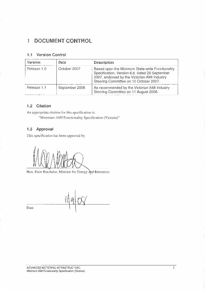
1.3 Approval
This specification has been approved by
'--'----'-------
Hon. Peter Batchelor, Minister for Energy a 1cl Resources
Date
ADVANCED METERING INFRASTRUCTURE Minimum AMI Functionality Specification (Victoria)
2
In early 2006, the Victorian Government formally endorsed the deployment of Advanced Metcring h~lhlstrltCfllrC (AMI) to all Victorian electricity customers consuming less than 160MWh per annum. An amendment to the F/ertririty Industry Act 20()() was passed by the Victorian Parliament in August 2006, providing the Government with legislative heads of po\ver to rnake Orders in Council (Ole) establishing a range of requirements for the deployment of AMI, including the setting of minimum AMI functionality, performance !evels and service levels.
Purpose Document This specification defines the minimum functionality and performance levels for AMI .',')'SleI11S'
deployed in Victoria.
2.3 Scope of application The requirements established by this specification apply to all metered electricity customer installations where the annllal consumption is less than 160MWh and where the electricity SIIPP(V is non-incidental.
The requirements in this specification apply to AMI s.ystems, These requirements are minimum requirements only and do not limit the implementation or AMI 8)'.\,'te1115,' that have functionality and performance that exceed the requirements of this specification.
ADVANCED METERING INFRASTRUCTURE 2 Minimum AMI Functionality Specification (Victoria)
3 MINI
(a) These functionality requirements apply to all AMI metering inSlallations for Victoria, However, the following lists the mini rnmn requirement for AM I meier configurations:
(I) single phase, single clement;
(2) single phase, single element with integrated controlled load contnctor;
(3) three phase direct connect;
(4) three phase direct connect with integrated single phase cOl1trolleclload contactor;
(5) three phase direct connect with integrated relay for operation of an external three phase controlleclload contactor; and
(6) three phase CTconnect (excluding supply COl1!octor).
(b) All meIer types shall meet the relevant requirements of AS62052.11. AS62053.22, AS620S3.21, and any pattern approval requirements of tbe National Measurement Institute.
3.2 Metrology
(a) The fonowing requirements shall apply to all AM! melers:
(I) single phase meters to be two quadrant meter,s' and separately record ocfive encrgv for import I and export in trading intervals;
(2) three phase meters to be four quadrant meters and to separately record active and reactive energy, importi and e.-\j)(}rt in tf{{ding intervals;
(3) record total acclUnlltalcd energy for each recorded channel of interval data;
(4) the resolution for colleclion of interval energv dato shall be at least 0. I kWh for ({ctive energy and 0.1 kV Arh for reactive energy;
(5) the resolution of energ)' consumption displayed on a meter's display shall be at least O. J kWh and 0.1 kV Arh for direct connected meters:
(6) for all meters, a minimum storage of 35 d({ys per channel of inlerwil energy data; and
0) all channels of illterl'{11 energy data shall he ahle to be read locally as well as remotely reacL
(b) An AM/meter shall be capable of meeling the requirements (including accuracy) of I)'pe 4, type 5 and type 6 meters (non-TOU capability).
(c) 'T'he values to be recorded for import ane! export arc actual values at the Connection Point for direct connect mefer:i.
(d) It shall be possible to remotely and locally select or configure whether import interval energy data is recorded or not.
(e) It shall be possible to remotely and locally select or configure whether reactive energy interval energy data is recorded from three phase meters or not.
1 It is noted that in accordance with the conventions of the National ElectriCity Market, export is when energy is exported from the network to a customer and import is when the customer delivers energy into the network.
2 For example, if a customer has local generation from photovoltaic cells, and during the first 20 minutes of a half hour period there was export from the network to the customer of 3 kWh and during the next 10 minutes the network imported 2 kWh from the customer, although the mathematical total for the half hour is 1 kWh exported, the aclual values recorded for that half hour would be, Export - 3 kWh, Import - 2 kWh
ADVANCED METERING INFRASTRUCTURE Minimum AMI Functionality Specification (Victoria)
3
\Vhen a mCfe!" has the Import interval DHia Recording setting set 10 disabled and import
energy is dctcctc.d, un Import Detected event shall he recorded ill the AM! ,vystem.
meters (a) When meiers are remotely read, the meter's tolo/ occllflllflated energy per collected channel shall
he able to be collected by the AMI system at least once every 24 hours,
(b) \Vhere melers are remotely read the il11en·'o/ energy doto per co/lecred channel shaH be ahle to be co/lected by the AA41 s)'stem at least once every 24 hours.
(c) When meters are locally read, the meter's tota/ ({CClllllUIOled energy per collected channel and the interpol ellergv dmo per collected channel sball be able to be collected,
(d) For individual reads of meters, it shall be possible to select up to 35 do.vs of intcrw!/ energy dotu to be collected per channel.
(e) The following shall also be able to be remotely and/or locally col/ected from the meter:
(l) settings:
(2) 1;']1e3
;
(3) clate;
(4) status indicators; and
(5) events logs.
Note that Appendix A details the events, settings and status indicators,
3.4 Supply Disconnect and Reconnect4
3.4.1 General Requirements
(a) AlIl7lcter types excluding C1' connected meters shall have a supply Confaclor.
(b) The AM! system shall support both local and remote disconnection, and local and rernote reconnection of cUstomer supply via the slIpply contoctor. When an AM/ lIleter performs a disconnect operation, all outgoing circuits from the meter shall be disconnected.
(c) To confirm the current state of a meter, the AM! system shall support "on-demand" remote polling of the mCfcr to determine whether the supply cOl/tactor is open or closed.
(d) The AA1! system shall complete on-demand polling commands, returning the SlfPPI.'Y' contactor position statu,,>, with the performance levels set out in section 4.
(e) The meter shall provide clear local visual indication of the status (open/closed) of l.he SllPP1.V ('01110('101'.
3.4.2 Disconnect
(a) The AMI.'i)'stem shall support both local and remote customer slIpply disconnect functionality,
3 The meter time and date needs to be cross referenced to an upstream system
4 The term "connect" is equivalent to the term "re-energisation" used in National Electricity Market documents.
Similarly the term "disconnect" is equivalent to the term "de-energisation".
ADVANCED METERING INFRASTRUCTURE Minimum AMI Functionality Specification (Victoria)
4
(b) For felt/Ole disconnects, the A!v1J s.-rslern shall cornplete the disconnect command. returning the S'IIPP1.v COli/actor position status, within the performance levels set out in section 4.
3.4.:2.1 Local DisconnectS
(n) Local discotllu!('{ via the meter shall only be able to be performed by an authorised technician. lJnauthorised persons shall be physically prevented from operating the supply contacfor to disconnect supply.
It) The AMi system shall supportlhe followmg:
(l) opening of the suppl.-v ('oil/actor performed locally;
(2) remote communication of the status (open/closed) of the ,'>'llfJply contoctor (if AIv!1 comnmnications are active) from the meter to the NMS; and
(3) event logging by the AM I ,vysrem of the local disconnection at that meter.
3.4.2.2 Remote Disconnect
(a) The AMI system shall support the following:
(l) opening of the slipply ('ol1facfor performed remotely;
(2) remole communication of the status (open/closed) of the supply COil lac/or (ii' AMI communications are active) from the meter to the NMS; and
(3) event logging by the AA1! s)'stem of the remote disconnection at that nUl/cr.
3.4.3 Reconnection
(a) The AM! system shall support botlliocal and remote customer supply reconnection fUllctionallty.
(b) When a command is performed remotely, the AMI system shall complete the command, returning the appropriate meter status to the NMS, within the performance levels set out in section 4.
3.4.3.1 Local reconnection
(a) Reconnection via the meter shall only be able 10 be performed locally by an authorised technician. Unauthorised persons shall be physically prevented from operating the SlfPP/:V contaetor to reconnect supply.
(b) The AM I s\'s/el71 shall support the following:
(1) closing of the slippl.v contoctor performed loca Il y;
(2J remote communication of the status (open/closed) of the slIpply cmllac/or (if AM! communications are active) from the meter to the NMS; and
(3) event logging by the A!v!! system of local reconnection at that meter.
3.4.3.2 Remote reconnection
(a) For safety, the meter shall support an auto-disconnect function jf load is detected flowing through the meter upon remote closing of the SllPPI.V contactor.
5 The circumstances in which local disconnection may occur include (but is not limited to) where:
(1) A technician is already on-site performing works and it is most efficient for the technician to perform the disconnection;
(2) An AMI meter is installed; however the communications infrastructure has not been rolled out or has failed.
ADVANCED METERING INFRASTRUCTURE Minimum AMI Functionality Specification (Victoria)
5
(h) The /u\4/ sy:N('m shill! suppnrllhe
(J) Closing or the slIpp(r cOIII{{etor pcrforrned remotely:
(2) Rernote communication of the status (open/closed) of the supply COl1to('{Of' from the meter to theNMS:
(3) Event logging by the AM! s'ysfem of remote reconnection;
(4) Meter \vill auto-disconnect if rnore than "X" \Vatts of load is detected flowing through the rneter for more than "Y" seconds during the auto-disconnect active period of "Z,· seconds after the supply contoctor is remote,ly closed, where:
(i). "X" range: 20 W - 2.5 kW per element, per phase, remotely anelloeally settable in 20 W increments:
(ii). "Y" range: 1- 3,600 seconds, remotely and locally scttable in 1 second increments:
(iii). "Z" range: 1- -',600 seconels, remotely anelloeally senable in I second increments:
(iv). Enabling/disabling of auto-disconnect function, remotely ancllocally configurable;
(v), Remote alarming to the NMS that the mOer has auto-disconnected; and
(vi). Event logging of auto-disconnection,
3.5 Time Clock Synchronisation
(a) Date and 1;'71(' vvithin mete}"s shall be maintained within 20 seconds of Australian Eastern Standard Time.
3.6 load Control
3,6, i Load control Groups
(al All loael control, whether controlled load (seelion 3.6.2) or /llilitl' control or other load (section 3.6.3) shall be able to respond to group commands and individual load control commands. Group commands Illay be delivered by broadcast.
(b) Groups shall provide for a minimuin of 20 primary groups (for use by Distributors), 200 secondary groups (for use by Distributors) and 200 tertiary groups (for use by R('foi/ers).
(c) The 200 teliiary groups are to be allocated across the /'clOi/cl:Y to allow several groups per retoi/er.
3.6.2 Controlled load management at meters
(a) The following are the features required of single phase or three phase meters with an internal controlled load contactor and three phase rneter::; equipped to operate an external controlled lond contactor:
(I) The controlled load contactor shall be remotely and locally programmable to respond to one primary group, one secondary group and one tertiary group;
(2) Storage in the meter of 1 set of 5 "turn on" and "turn off' times applicable to weekdays and I set of 5 "turn on" and "turn off' times applicable to weekend days;
(3) "Turn on" and "turn off" times are remotely and locally seltable for each meter individually and in groups through the AM I communications system;
(4) Meters shall recognise "turn on" and "turn off' commands that will override the switching program stored in the meter. The "turn on" and "turn off' functionality shall be individually
ADVANCED METERtNG tNFRASTRUCTURE Minimum AMI Functionality Specification (Victoria)
6
addrcs~ah1e or groups. The action of u remote "turn on" or "'turn ofT'" conlllwnd shall disahle or override the preset time based hturn on'" and "(urn otT'" sche.dule for a programmable period between 0 and 2,880 rninutes, settable in 1 minute increments:
(5) 111et('1',l.' with an integrated single phase controlled load contactor are to have "boost" functionality. This functionality shall be able 10 be remotely and locally enabled or disablecL When the meter's' "boost" function is activated, the meter \-vill energise the controlled load for a preset time, which is remotely and locally programmable from 1 to 6 hours in half hour increments. \Vl1en the Boost Primacy setting is set to di:--;ab!ed and a Controlled Load Override "turn off" command per section 3.6.2.a (4) is active within the tnefer, activation or the mcter's "boost" function will not energise the controlled load;
(6) Meters with integrated single phase controlled load contactor shall have a controlled load contacto1' \-vith a minimum current rating of 31.5 A resistive (AC I rating) and a nominal voltage rating of 230 Vac();
0) Meters for three phase load control, shall have an integral relay with a minimum rating of 1 A, and a nominal voltage rating of 230 Vac for operation of an external load control contactor; and
(8) The meter shall provide clear local visual indication of the status (open/closed) of the controlled load contactor.
3.6.3 Utility Control of Other Load
(a) The AMlsY.I,·tel11 shall have the capability to communicate to "other load control" devices through the AMI communications network. The following are the requirements of these "other load control" devices:
(I) "Other load control" devices shall be remotely and locally programmable to respond to one primary group, one secondary group, and one tertiary group;
(2) Storage in the "other load control" devices of j set of 5 "turn on" and "turn off' times applicable to week do)'s and 1 set of 5 "turn on" & "turn off" times applicable to weekend do.).'s;
(3) "Turn on" and "turn ofr" times are remotely and locally scttahle individually and in groups, through the AM! communications system; and
(4) Recognition of "turn on" and "turn off" commands that will override the stored switching program. The "turn on" and "turn off' functionality shall be individually addressable or by groups. The action of receiving a remote "turn on" or "turn off" command shall disable or override the preset time based "turn on" and "turn off' schedule for a remotely and locally settable period between 0 and 2,880 minutes, settable in I minute increments.
3.6.4 Random Load Control Switching Delay
(a) As specified in Table I, certain load control switching, whether controlled load management at meters (section 3.6.2) or utility control of other load (section 3.6.3), shall be randomly delayed up to a maximum configurable period of time, from 0 to 60 minutes, which shall be remotely and locally settable in 1 minute increments:
6 The tolerance on the rated voltage is as per the Electricity Distribution Code
ADVANCED METERING INFRASTRUCTURE Minimum AMI Functionality Specification (Victoria)
7
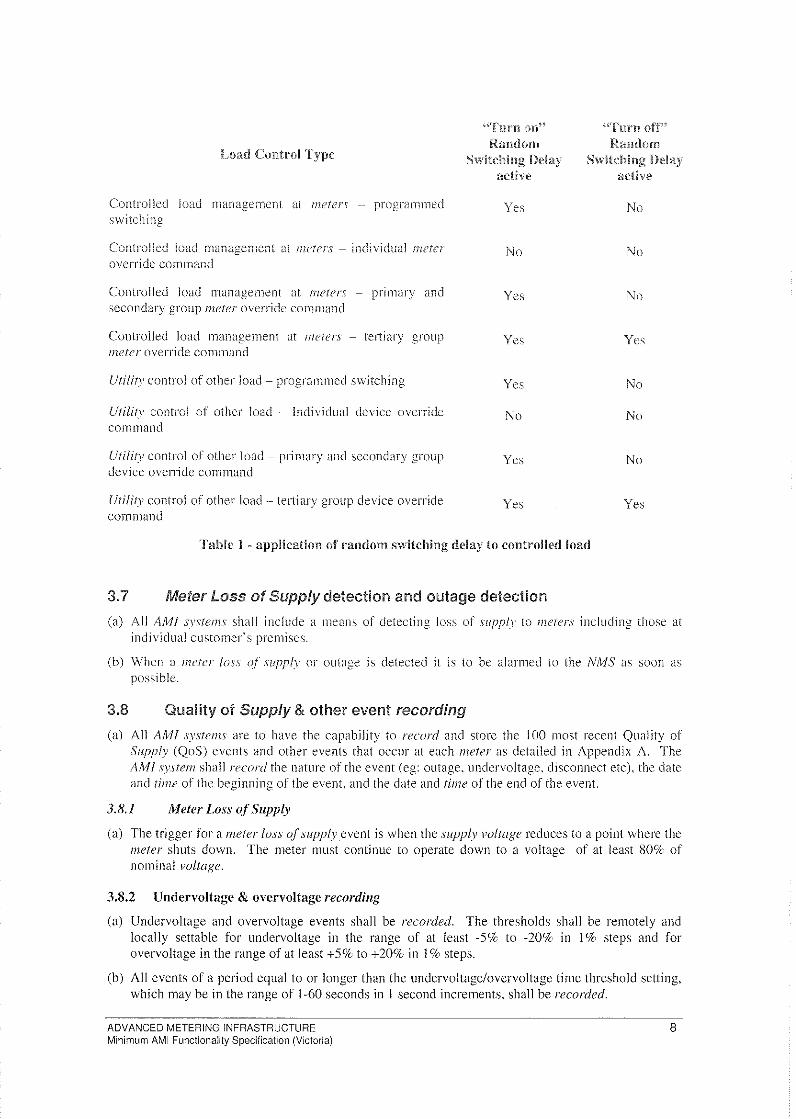
Load Control
Controlled load rnanagcmcnl at {neter,",' -- programmed switching
Controlled load rnanagcrncnt at met(T,j' - individual ;nett'r
override commcll1d
Controlled load management at {Julte!'...,' - primary and secondary group 171e1er override command
Controlled load management at meters - tertiary group meIer override cOlllmand
Uti/h)' control of other load - programmed s\vitching
Utility control of other load - Individual device override command
Uti fit)" control or other load - primary and secondary group device override command
Utilit}' control of other load - tertiary group device override command
HTurn on'~ Random
active
Yes
No
Yes
Yes
Yes
No
Yes
Yes
Table I - application of random switching dclay to controlled load
3.7 Meter Loss of Supply detection and outage detection
""Turn off')~ Random
active
No
No
No
Yes
No
No
No
Yes
(a) All A/v1l sy,\,'fems shall include a means of detecting loss of 5;lfpply to meters including those at intli vidual cllstomer's premises.
(b) 'When a meter joss qf slIpp/."r or outage is detected il is to be alarmed to the NMS as soon as possible.
3.8 Quality of Supply & other event recording
(a) All AM! systems are to have the capability to record and store the 100 1110st recent Quality of Supply (QoS) events and other events that occur at each meter as detailed in Appendix A. The AM} system shall record the nature of the event (eg: outage, unclervoltagc, ciisconnect etc), the date ancllimc of the beginning or the event, and the dale and time of the end of the event.
3.8.1 Meter Loss 0.( Supply
(a) The trigger for a meter loss (~f supply event is when the supply voltage reduces to a point where the meter shuts down. The meter must continue to operate down to a voltage of at least 80% of nominal voltage.
3.8.2 Undervoltage & overvoltage recording
(a) Undervoltage and overvoltage events shall be recorded. The thresholds shall be remotely and locally settable for undervoltage in the range of at least -5% to -20% in 1 % steps and for overvoltage in the range of at least +5% to +20% in 1 % steps.
(b) All events of a period equal to or longer than the undervoltagelovervoltage time threshold setting, which may be in the range of 1-60 seconds in I second increments, shall be recorded.
ADVANCED METERING INFRASTRUCTURE Minimum AMI Functionality Specification (Victoria)
8
For cach evcnj the minimum vol/age that occurred during the period shall be recorded. For each overvoltage event the maximum I'oftagt! that occurred during the period shall be recorded. For three phase mcters, the phnscs affected shall also be recorded.
3.8.3 Eve!]ts for daily col/ectioll
(a) For each meter the following events shall be recorded in the AM! s.vsteFl1 and be available for daily collection:
(j) lv1eft'!" /o.)'s (~rsllpply;
(2) Boost activated;
(3) Tamper detected;
(4) the ,YlIpply con/uctor has changed state - open or closed - for any cause;
(5) Import Ellergv detected;
(6) Controlled load override;
(7) HAN events as detailed in 3.10(h) and3.10(i); and
(8) Whenever there is a change ofAMl meter settings that is performed locally or remotely.
3.8.4 Other events
(a) The complete list of events whieh must be logged is detailed in Appendix A.
3.9 Supply Capacity Control
(a) AMlmeter,"," (except CTconnected meters) shall have two SlIPP!.V capacity limit settings -"" a normal limit and an emergency limit. This functionality applies only to direct connected meters (ie: does not apply to CT connected meters).
(b) All supply capacity control settings shall be remotely and locally configurable.
3.9.1 Normal supply capacity limit operation
3.9.1. J \Vhen energy is exported from the network to a customer
(a) The SIlPP/:V cont(!ctOr shall open if the average k\V demand across the last X number of trading intervals is greater than the demand limit (Y kW), where:
X is settablc from I to 10 trading interl'a/s in increments of 1 trading illter),{ll; and
Y is settable from O.S to 99 kW in incremcnts of 0.5 kW .
3.9.1.2 When energy is imported from a customer to the network
(a) The supply COJ1tactor shall open if the average kW demand across the last U number of trading intervals is greater than the demand limit (V kW). where:
U is settable from I to 10 trading intervals in increments of I trading interval; and
V is settable from 0.5 to 99 kW in increments of 0.5 kW.
3.9.1.3 Enabling. disabling and event recording
(a) The supply capacity control functionality shall be able to be remotely and locally enabled and disabled.
(b) If the supply contactor has opened due to the demand having exceeded the demand limit. the supply contactor shall remain open for a period of T minutes (where T is sellable from I to 60 minutes in I minute increments) and then automatically reclose.
ADVANCED METERING INFRASTRUCTURE Minimum AMI Functionality Specification (Victoria)
9
'The disconnection and any ';ub"equcnt rcconnection shall be recorded as evenis as described in section 3,8.4.
3.9.2 callac:l!y limit o""n:","o when energy is eXlmried from the network to a customer
(a) The AMI S)'sfelll shall have the capability to remotely and iocally activate or de-activate the emergency suppl.y capacity limit in AM/meters by either primary or secondary groups of meters, or by commands sent to individual meters.
(b) When the emergency SliPP!.}' capacity limit is activated this will then take precedence over the normal supply capacity limit, except where the normal supply capacity limit is lower than the ernergency supply capacity limit.
(c) The emergency SllPPI."r' capacity limit functionality in AM! meters must be capable of being remotely and locally enabled or disabled for selected meters.
(d) When the emergency supp!.}' capacity limit is activated, the supply con{{fctor shall open if the average kW demand across R minutes is greater than the cmergency .VIIPP!Y capacity limit (S kW) where:
R is scttable from 0 to 60 minutes in increments of 1 minute: and
S is settable from D.S kW to 99kW in increments of D.S kW.
(e) If the supply con{(tcfor has opened due to the demand having exceeded the emergency demand limit, the contactor shall remain open for a period of T minutes (where T is settable from 1 to 60 minutes in 1 minute increments) and then automatically reclose.
3.10 Interface to Home Area Network (HAN)
(a) All direct connected AMI meters shall be certified to operate as an Energy Service Portal (ESP) as detailcd in the ZigBee(l;-l Alliance Smart Energy Profile (SEP) Specification (ZigBec(lil Document Numbers 075356rl4 and 084914r03).
(b) The ESP shall operate in the 2.4GBz ISM hand and comply with the Radiocommunications (Low Interference Potential Devices) Class Licence 2000 as amended - made under sections 132 and 135 of the Australian Radiocommunications Act 1992. The ESP shall opcrate with an effective radiated power of alleast 50mW.
(c) The ESP shall be configured to operate in a Utility Private HAN and shall support all ESP mandatory and optional clusters.
(d) Communications to all HAN devices shall first require that those devices join the Utility Private HAN llsing the secure key establishment method.
(e) The ESP shall be capable of interacting with a minimum of 16 Smart Energy Profile certified devices that have joined the Utility Private HAN. The AMI s)'Stem shall support an average of 3 BAN devices per ESP.
(f) The AMI system shall enable the interactions between the head end and the ESP as detailed in the SEP.
(g) The AMI system shall provide to the ESP, and the ESP shall store, the tariff information required to allow the ESP to populate the fields in the SEP publish price command for implementation of a TOU tariff (with at least I set of 7 TOU periods for weekdays, I set of 7 TOU periods per Saturday and I set of 7 TOU periods per Sunday) and critical peak price notification.
(h) The meter shall record as an event when tariff information is updated or changed in the ESP.
(i) The meter shall record as an event any confirmation or status response (arising from a command from the AMI system) that the ESP receives from HAN devices, triggered by:
ADVANCED METERING INFRASTRUCTURE Minimum AMI Functionality Specification (Victoria)
10
(1) ::) message confirmation (as detailed in the SEP) from a }-IAN device
a load control report evenl status detailed in the SSP) from a IIAN device
(3) a notification that a I-IAN device has joined or failed to join the Utility Private HAN
1
(a) The AM! s.l,'stelll shall be capable of detecting and recording as an event attempts to tamper with the meter,
3.12 Communications and data security
(a) The AM/ s.I'sfern shall ensure all communications between system cornponents shall be secured in such a way as to prevent unauthorised interception and modification.
(b) All device elements shall contain the necessary security to prevent unauthorised access or modification of data.
3.13 Remote Firmware Upgrades
(a) The AMI system shall have the capability to remotely upgrade the firmware in AM! sys'lcm devices including data concentrators and meters (and Zig8ee (;lj Energy Services Portal).
(b) It shall be possible to remotely change firmware without impacting the metrology functions of the meter,
3.14 Self registration of meters
(a) Meters shall have the capability to sclfregister with the NMS.
ADVANCED METERING INFRASTRUCTURE Minimum AMI Functionality Specification (Victoria)
11
4 E The following are the Alv!! sy,vfcm performance levels required.
(a) These performance levels apply to the complete AM! s.vsfem, but not to any upstream systems or downstream systems.
(b) These performance levels specifically apply from the NIV15,' to the meter and return.
(c) It is noted that all AM} system may include cornlllllllications links provlded by third parties such as telec()mmunications carriers and which afC outside of the control of the party that operates the AMI syslem.
(d) The performance levels are average performance levels over the period of a year and exclude force majeure events,
Performance levels for collection of daily meter readings
(a) The follO\ving are the performance levels required for the daily coI/ectio!1 of the previous trading (/o.,>,'s inferl'{iI energy data and 1010/ oeeunwlatcd energy (as required in section 3.3):
(1) All data from 99';i(. of meters \vithin 4 hours after midnight; and
(2) All data from 99.9'J() of 111eters within 24 hours after midnight.
4.2 Performance levels for remote reads of individual meters
(a) The performance level of an individual read (refer to section 3.3) applies to the collcction of seven da)'s of interval energy data and the current {otal accumlliated energy from a particular AMI meter. The performance level required is:
(I) Action performecl at 90% of meters within 30 minutes;
(2) Action performed at 99'iC of melers within I hour; and
(3) Action performed at 99.9% of meters within 6 hours.
(h) The total number of individual IIwfers read in any 24 hOllr period can be lip to 2(;( of the installed, operational AMI meter population.
4.3 Performance levels for remote connect/disconnect
(n) The performance level required for indivicluallJu!lerS is:
(1) Action performed at 90Sf-· of melers 'vvithin 10 minutes:
(2) Action performed at 99% of meters within I hour; and
(3) Action performed at 99.9'* of meters within 6 hours.
(b) The total number of connects/disconnects commancis to individual melers in any 24 hour period can be up to 2% of the installed, operational AM! meter population.
4.4 Performance levels for remote load control commands
(a) The actions covered in this category are specifieci in section 3.6 for Controlled L.oad Management and for Utility Control of Other Loads. For commands to any primary, secondary or tertiary group of meters the performance level required is:
(1) Action performed at 99% of melers within I minute.
(b) For commands sent to individual meters, the performance level required is:
(I) Action performed at 90% of meters within 30 minutes;
(2) Action performed at 99% of meters within I hour; ancl
ADVANCED METERING INFRASTRUCTURE Minimum AMI Functionality Specification (Victoria)
12
Action nerlmnwcl at 99.9(/ of meters within 6 hours.
(c) The total numher of lond control cornmands to individual meters in any 24 hour period can be up 10 2 (X· of the installed, operationa! A/'d! flitter population
4.5 Meter loss :;u,pp,<yand oUlage detec:tiQln
(a.) Alarms to he received within one hour for 90s{'· of meters.
4.6 Performance levels for emergency supp/ycapacity limiting
(a) The actions covered in this category are specified in section 3.9.2 for emergency ,";upply capacity control. I::"or commands to any primary or secondary group of meters the performance level required is:
(I) Action performed at 90% of meters within I () minutes; and
(2) Action performed at 99% of meters within 1 hour.
(b) For commands sent to individual meters, the performance level required is:
(1) Action performed at 90S{· of meters within 30 minutes;
(2) Action performed at 99% of meters \vithin 1 hour; and
(3) Action performed at 99.9% of meters within 6 hours.
(c) The total number of load control commands to individual meters in any 24 hour period can be up to 2% of the installeci, operational AMI meter population.
4.7 Performance levels for remotely altering settings in meters
(a) The performance level required for individual meters is:
(1) Action performed at 909(: of/rleters within 30 minutes;
(2) Action performed at 99% of meters within 1 hour; and
(3) Action performed at 99.9'1r of melers within 6 hours.
(b) The total number of commands to alter settings at individual meier::; in any 24 hour period can be up to 2(k of the installed, operational AA11mefer population.
4.8 Performance levels for remotely reading settings and status indicators from meters
(a) Performance level required for reading all the settings and status indicators of an individual 1neter (refer section 3.3) is:
(I) Action performed at 90% of rneters within 30 minutes;
(2) Action performed at 99('/0 of meters within 1 hour; and
(3) Action performed at 99.9% of meters within 6 hours.
(b) The total number of commands to read settings and status indicators from individual meters in any 24 hour period can be up to 2% of the installed, operational AMI meter population.
4.9 Performance levels to remotely read events logs
(a) The performance level required for reading the full event log that pertains to an individual meter is:
(I) Action performed for 90% of meters within 30 minutes;
(2) Action pe,formed for 99% of meters within I hour; and
ADVANCED METERING INFRASTRUCTURE Minimum AMI Functionality Specification (Victoria)
13
Actiun
(b) The totalllulllbc:r of cornmands tu read the full event log pertaining to individual meters in any 24 hour period can be up to 2q of the installed, operational AMI meter population.
(c) To reaclthe even! logs pertaining to aljlll{;'ters:
(I) The data pertaining to 99.59(, of meters in ! vv'eek; and
(2) The (bH<:1 pertaining to 99.9(1<: of meiers in 2 weeks.
4.10 Performance 1"",,1<: associated the Home Area Network (HAN)
(a) The Al\Ill system shall support up to (1 HAN instructiolls per day being sent to the ESP.
(b) The performance level required for HAN instructions is:
(1) HAN inSfrllCfioJl received by 98(k or ESPs in 3 hours;
(2) HAN instrllction received by 99.9t;{., of ESPs in 12 hours
ADVANCED METERING INFRASTRUCTURE Minimum AMI Functionality Specification (Victoria)
14
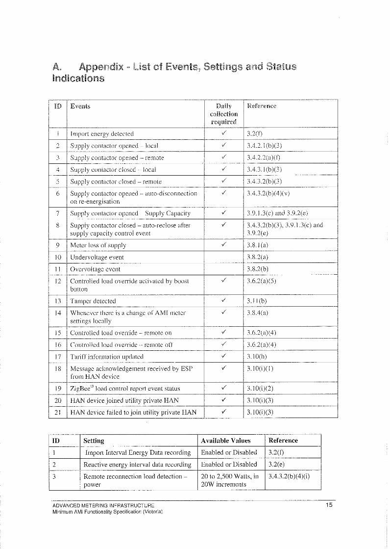
Indications
I")T Events
i I
I
I
j Import energy detected
2 Supply contactor openecl- local
3 Supply contactor opened --- remote
4 Supply contaclor closed -local
5 Supply cOlltaclor closed - remote
6 Supply contactor opened - auto-disconnection on re-energisation
7 Supply contactor opened - Supply Capacity
8 Supply cantactor closed - auto-reclose after supply capacity control event
9 Meter loss of supply
10 Undervoltage event
II Overvoltage event
12 Controlled load override activated by boost button
13 Tamper detected
14 Whenever there is a change of AMI meter settings locally
15 Controlled load override remote on
16 I Controlled load overricle remote off
17 Tariff information updated
18 Message acknowledgement received by ESP from HAN device
19 ZigBee® load control report event stalus
20 HAN device joined utility private HAN
21 HAN device failed to join utility private HAN
ID Setting
I Import Interval Energy Data recording
2 Reactive energy interval data recording
3 Remote recol1llectlon load detection -power
ADVANCED METERING INFRASTRUCTURE Minimum AMI Functionality Specification (Victoria)
~-- --""
Daily Reference collection required
-/ 32(0
-/ 3.4.2.1 (b)(3)
-/ 3.422(a)(f)
-/ 3.43.I(b)(3)
-/ 3.4.3.2(b )(3)
-/ 3.4.3.2(b)( 4)( v)
-/ 3.9.1.3(c) and 3.9.2(e)
-/ 3.4.3.2(b)(3), 3.9.1.3(c) and 3.9.2(e)
-/ 3.8.1 (a) ---
3.8.2(a)
3.8.2(b)
-/ 3.6.2(a)(5)
-/ 3.11 (b)
-/ 3.8.4(a)
-/ 3.6.2(a)(4) ---
-/ 3.6.2(a)(4)
-/ 3.10(h)
-/ 3.1 O(i)( I)
-/ 3. I O(i)(2)
-/ 3.IO(i)(3)
-/ 3.100)(3)
Available Values Reference
Enabled or Disabled 3.2(1)
Enabled or Disabled 3.2(e)
20 to 2,500 Watts, in 3.4.3.2(b)( 4 )(i) 20W increments
15
II) ."eithw ••.....•. .......: •. ::. .•.•.• - ---- -~"'-"'-,--,----------------- ----
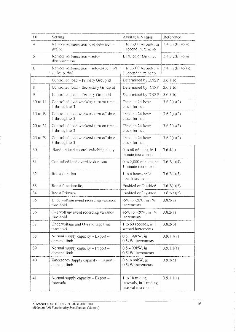
4 Remote reconneclion load detection -period
1- ... _._.- ------------ ---,--""
15 Rernote reconnection - auto-, disconnection I
I----~-- --.-~-------------------------~---- ------~---
I 6 Remote rcconncction - auto-disconnect
active period I _.
7 Controlled load - Primary Group id
8 Controlleclload "'" Secondary Group id
9 Controllcclload -, Tertiary Grollp iei
10 to 14
I Controlled load weekday turn on time-I through to 5
15 to 19 Controlled load weekday turn oil time-I through to 5
----- ------,,-,-,--,--,,-
20 to 24 Controlled load weekend turn on time -I through to 5
I 25 to 29 Controlled load weekend turn off time-
I I through to 5 r-- """"" ... ~ --"".~
3D Random load control s\vitching delay
31 Controlleclload override duration
32 Boost duration
33 Boost functionality
I 34 Boost Primacy I ---.
1
35 Undenioltage event recording variance threshold
. , 36 Overvoltagc event recording variance
threshold ---"~~---
37 Undervoltage and Overvoltage time threshold
38 Normal supply capacity- Export· .. demand limit
39 Normal supply capacity - Import-demand limit
40 Emergency supply capacity - Export-demand limit
41 Normal supply capacity - Export-intervals
ADVANCED METERING INFRASTRUCTURE Minimum AMI Functionality Specification (Victoria)
-------- .....................
AvaHable Values Reference -------------- ----------,~"-,-''''-,,,~,-~ - --- ---------
I to .1.WO seconds, in .1 2Ih)(' I second increments
._-------Enabled or Disabled H.3.2(b)( 4)(1 i i)
-"-"-""""""---._. --------- ---------~,,-"'~"""-
I to 3,600 seconds, in .lA.3.2(b)( 4 levi) I second increments I Determined by DNSP 3.6.I(b)
Determined by DNSP 3.6.I(b)
Determined by DNSP 36.I(b)
Timc, in 24-hour 3.6.2(a)(2) clock format
Time, in 24-hour 3.6.2(a)(2) clock format
Time, in 24-hour 3.6.2(a)(2) clock format
Time, in 24-hour 3.6.2(a)(2) clock format
o to 60 minutes, in I 3.6.4(a) minute increments
o to 2,880 minutes, in 3.6.2(a)(4) I minute increments
I to 6 hours, in Y2 3.6.2(a)(5) hour increments
Enabled or Disabled 3.6.2(a)(5)
Enabled or Disabled 3.6.2(a)(5) ._-
-ssr to -20%, in I '7r 3.8.2(a) increments
+sclc to +20';;:" in 1% 3.8.2(a) increments
-,---,-- ,,--,-
I to 60 seconds, in I 3.82(b) second increments
0.5 - 99kW, in 3.9.1.1 (a) 0.5kW increments
D.S - 99kW, in 3.9.1.2(a) D.SkW increments
D.S to 99kW, in 3.n(d) D.SkW increments
I to 10 trading 3.9.I.I(a) intervals, in I trading interval increments
16
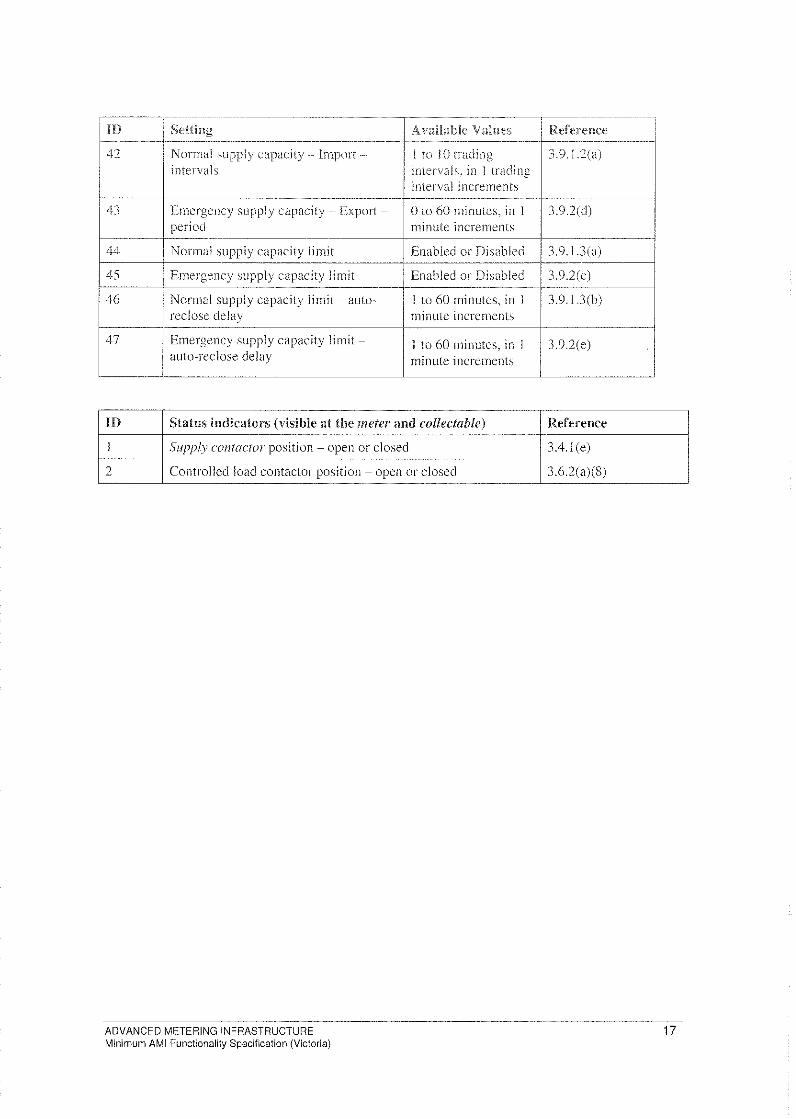
m ""liJi", Available Vah""
42 Normal supp!y capacity lrnport -- J 10 J {} trading intervals intervals, in ! trading
interval increments •.... _--------
Emergency supply capacity .. Export - o to 60 minutes, in I period minute increments
44 """"'" supply capacity iimir Enabled or Disabled ..
45 I Emergency supply capacity limit Enabled or Disabled J Normal supply capacity limit - auto- 1 to 60 minutes, in 1
t reclose delay minute increments
Emergency supply capacity limit - I to 60 minutes. in I auto-reclose delay rninute increments
m Status indicators (visible at tile meter and collectable) ---,--,-"--- -~---'"-,,-,,-~""---
I Supply cOil/actor position - open or closed ----2 Controlled load contaclor position - open or closed
ADVANCED METERING INFRASTRUCTURE Minimum AMI Functionality Specification (Victoria)
Reference -------- ----------
3.9.1.2(a)
f--3.9.2(d)
---~-.•.
3.9.1.3(a) I
3.9.2(c)
3.9.I.3(b)
3.9.2(e)
-----.J
Reference
3.4.1 (e)
3.6.2(a)(8)
17
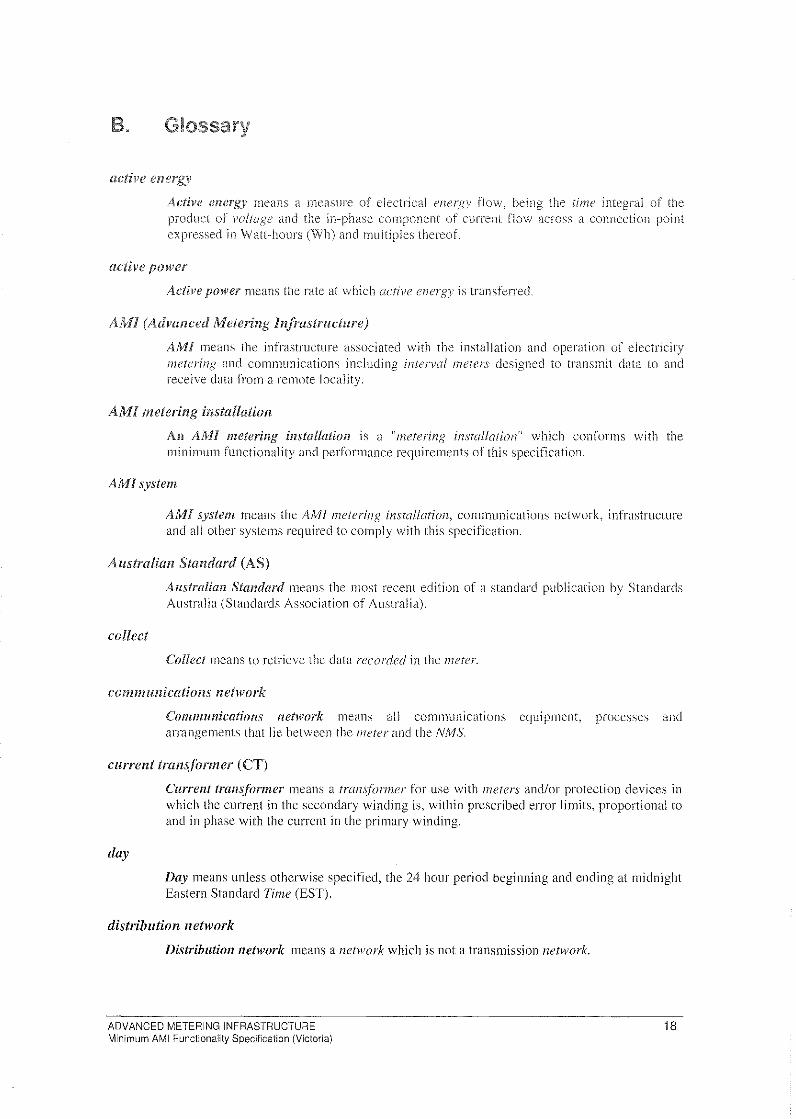
active energy
Active energy means a measure of dectrical energ)' flow, heing the time integral of the product of polioge and the in-phase component of current now across a connection point expressed in Wall-hours (Wh) nndlllllitipies thereof.
active power
Active power means the rate at which (lcth!(' el1ergy is transferred,
AMI (Advanced Metering b~frastruct"re)
AMl means the infrastructure associated \vith the installation and operation of electricity metering and communications including intenal meters designed to transmit data to and receive data from a remote locality.
AMI metering installation
An AMI metering installatioll is a "metering in.)1alIation" which conforms with the minimum functionality and performance requirements of this specification.
AM! system
AMI sy,,;'tem means the AN!! metering instolla/;on, communications network, infrastructure and all other systems required to comply with tbis specification,
Australian Standard (AS)
collect
Australian Standard means the rnost recent edition of a standard publication by Standards Australia (Standards Association of Australia).
Collect means to retrieve the data recorded in the }}u:!ter.
communications network
Communication" network means ali communications equipment, processes and aITangements that lie between the meter and the NMS.
Cllrrellt trallsformer (CT)
day
Current tram.jiJrmer means a tr{{n.~f(}rl11er for use \vith meters and/or protection devices in which the current in the secondary vvinding is, within prescribed error limits, proportional to and in phase with the current in the primary winding.
Day means unless otherwise specified, the 24 hour period beginning and ending at midnight Eastern Standard Time (EST)<
distribution network
Distribution network means a net~F()rk which is not a transmission network.
ADVANCED METERING INFRASTRUCTURE Minimum AMI Functionality Specification (Victoria)
18
energy
Distribution means a dij'lrihlflio{l nenvork, together with the connection assets associated with the distribution netl-vor/(, which is connected to another transmission or dis'triiJlltiull system. Connection assets on their o'vvn do not constitute a distriiJution system.
Fl1en'v means active en(Ttr'yi and/or reactive cl1crr{I"<
energy data
Energy dara means interval eHergy data and total acclImulated ellerg}'.
Export
Export means the delivery of energy from the network to a customer.
HAN Instruction
Import
HAN instruction means up to 256 bytes of data (including but not limited to tariff information, SEP commands or messages) sent to the ESP via the AM! System.
Import means the delivery of energy from an end-usc customer into the distri/Jution network.
interval energy data
Interval energy data means the data that results from the measurement of the now of electricity in a power conductor where the data is prepared by a data logger into intervals which correspond to a trading il1lerl'a/ or arc sub-multiples of a lr(l(/;ng interval.
interval meter
Interval meter means a meter that records interpol energy data.
ISM band
ISM hand llleans one of the Industrial Scientific and Medical radio frequency bands as defined by the International Telecomlllunication Union in sections 5< 138,5.150, and 5.280 of the Radio Regulations.
Local disconnect
market
meter
Local disconnect means the operation of the supply contactor to effect a disconnection of supply not by the AMI comlllunications system but performed locally at the meter by alternative electronic means.
Market means any of the markets or exchanges described in the National Electricity Rules, for so long as the market or exchange is conducted by NEMMCO.
Meter means a device complying with Australian Standards which measures and records the production or consumption of electrical energy.
ADVANCED METERING INFRASTRUCTURE Minimum AMI Functionality Specification (Victoria)
19
meter loss
J'vleter loss (~l means that the po\ver l'o!tuR,c has reduced to point \vhere the meter can no longer function, generally hecause it's power supply has shutdown.
metering data
Metering data means the data obtained from a metering if1.l,;wl/mioJl, the processed data or substituted elata,
metering illstal/ation
MeterinR installation means the assembly of components and/or processes that are controlled for the purpose of metrology and vv'hich lie between the metering po;nt(.\) or non metered connection point and the poinf of connection to the telccotluTiunicariolls lIet~v(}rk< The assembly of components may include the combination of several mctering points to derive the metering dahl for a cOllnection point. The metering install(ltion must be classified as a revcnlle metering hlsta/lmioJ] and/or a check flwtering instal/atioll.
metering point
Metering point means the poinl of physical connection of the device measuring the current in the power conductor.
Metrology Procedure
Metrology Procedure means the procedure developed and published by NEMMCO in accordance with clause 7.14 of the National Electricity Rules.
NEM (National Electricity Market)
National Electricity Market means the wholesale electricity market operated by NEMMCO under the National Electricity Rilles.
Natiol1al Electricity Rules (NER)
Natioual Electricity Rules means the rules made by the Australian Energy Markel Commission (AEMC) under the National Electricity (South Australia) Act 1996 (the "new" National Electricity La\-v) that governs the operation of the Nation({1 Electrici(r Morket.
NEMMCO
network
NEMIHCO means the Nalhm(ll Electricity Market Management Company Limited ACN 072 010 327, the company which operates Hnd administers the market in accordance with the Nathmal Electridty Rilles.
Network means the apparatlls, equipment, pIma and buildings used to convey, and control the conveyance of, electricity to customers (whether wholesale or retail) excluding any connection assets. In relation to a Net).vork Service Provider, a net).-vork owned, operated or controlled by that Net)ovork Servh'e Provhler<
NMS (Network Management System)
Network Management System means the component of an AMI sys'lem that manages the AMI communications network.
ADVANCED METERING INFRASTRUCTURE Minimum AMI Functionality Specification (Victoria)
20
Plant means, in relation to a COfllk'ctioll point, all equipment involved in generating, utilising or transmitting electrical energ)'.
reactive energy
record
Reactive energy means a measure in varhollrs (varh) or the alternating exchange of stored energy in inductors Rnd capacitors, which is the time--integral of the product of voltage and the out-oY-phase component of current flow across a connection point.
Record means to store the measured parameter in the meter
remote disconnect
Retailer
RCll10te disconnect rneans the utilisation of the communication system to disconnect the customer's ,Yllpply at the meter by lhe operation the AMI contactor.
Retailer means an entity which maintains a reNd/licence and is the market participant that is financially responsible for a cllstomer's connection point.
retaillicellce
Retail licence means a licence issued by the Essential Services COl1lmiss;rm under the Electricity Industry Act 2000 to sell electricity.
revenue meter
Revenue meter means the meter that is used for obtaining the primary source of metering dara.
self registering
supply
Self registering means the ability of the meIer upon being added to the NMS of the AMI system when installed to register or configure itself with the AMI s)'stem so that it will cornmence performing its proper functions without further local intervention.
Supply means the delivery of electricity at a connection point.
supply cOlltaclor
time
Supply contactor means the contactor in the meter til at, when opened, causes a premise with slipply to be disconnected and, when closed, allows a premise with supply to become connected.
'h Time means Eastern Standard Time, being the time at the 150 meridian of longitude east of Greenwich in England, or Co-ordinated Universal Time, as required by the National Measurement Act, 1960.
ADVANCED METERING INFRASTRUCTURE Minimum AMI Functionality Specification (Victoria)
21
lolal accum,rll,Uea energy
Total accumulated energy means the totai or accumulated amount or energy measured and recorded pef channel of a mcf(!r since the installation of the nu:ter or the resetting of the value.
Trading day is the same as H do)' and means a 24 hour period that finishes at midnight Eastern Standard Time.
trading interval
Trading interval means a 30 minute period ending on the hour (Eastern Stnndard Time) or on the half hour and, where identified by a (inu:" means the 30 minute period ending at that lime.
transformer
Tran~f()nner means a plan! or device that reduces or increases the voltage Of alternating current.
Type 4 meter
Type 4 meter means a remotely read electricity interval meter that is a component of a compliant fype 4 metering instal/ation, that meets the requirements of the National Electrh.'ity Rules and the metrology procedure,
Type 5 meter
Type 5 meter means an electricity inferl'{i/ meter that is a component of a compliant type 5 metering instal/ation, that meets the requirements of the National Electricit)' Rilles and the rnetr%gr procedure.
Type 6 meter
Utility
voltage
Type 6 meter means an accumulation electricity meter that is a component of a compliant type 6 metering insw//afiol1 that meets the requirements of the Natiollal Elcctrici(r Rilles and the metr%gy procedure.
Uti/ify means either an entity operating a distribufhm nctwork or a retail entity that sells electricity to cLlst.omers<
Voltage means the electronic force or electric potential between two points that gives rise to the flow of electricity.
ADVANCED METERING INFRASTRUCTURE 22 Minimum AMI Functionality Specification (Victoria)