advanced concepts in high resistance grounding …wmea.net/technical...
TRANSCRIPT
Sergio A. R. Panetta, M. Eng., C. Eng., P.Eng.,
ADVANCED CONCEPTS IN HIGH RESISTANCE GROUNDING
Advanced Concepts in High Resistance Grounding WMEA , Rapid City, SD, May 29th 2014
Content
• Resistance Grounding • LV systems • MV Systems • Energy dissipation in the fault • Case Studies • Recommendations
Advanced Concepts in High Resistance Grounding WMEA , Rapid City, SD, May 29th 2014
Rationale for this paper Resistance grounding is the most misunderstood
Most articles focused on simple single source systems
Resistor applied to Neutral only up until now.
Share Advances in the art of Resistance Grounding
Future work Advanced Concepts in High Resistance Grounding WMEA , Rapid City, SD, May 29th 2014
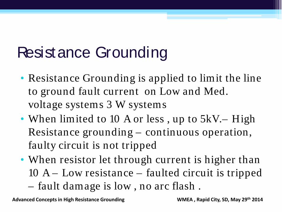
Resistance Grounding
• Resistance Grounding is applied to limit the line to ground fault current on Low and Med. voltage systems 3 W systems
• When limited to 10 A or less , up to 5kV.– High Resistance grounding – continuous operation, faulty circuit is not tripped
• When resistor let through current is higher than 10 A – Low resistance – faulted circuit is tripped – fault damage is low , no arc flash .
Advanced Concepts in High Resistance Grounding WMEA , Rapid City, SD, May 29th 2014
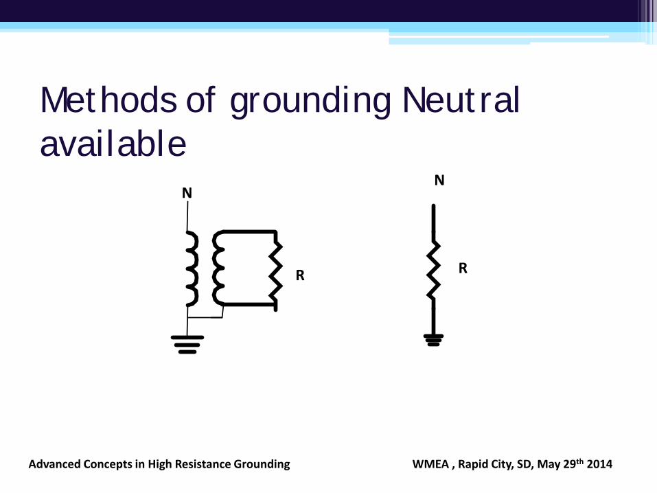
Methods of grounding Neutral available
N
R
N
R
Advanced Concepts in High Resistance Grounding WMEA , Rapid City, SD, May 29th 2014
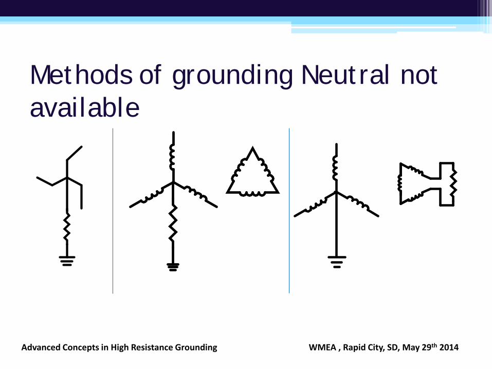
Methods of grounding Neutral not available
Advanced Concepts in High Resistance Grounding WMEA , Rapid City, SD, May 29th 2014
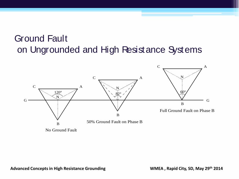
Ground Fault on Ungrounded and High Resistance Systems
N
60°
B
C A
N120°
B
C A
G
No Ground Fault
Full Ground Fault on Phase B
N
B
C A
50% Ground Fault on Phase B
G
82°
Advanced Concepts in High Resistance Grounding WMEA , Rapid City, SD, May 29th 2014
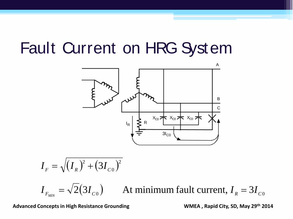
Fault Current on HRG System A
B
C
RXC0 XC0 XC0
3IC0
IR
( ) ( )20
2 3 CRF III +=
( ) 00 3 current,fault minimumAt 32 CRCF IIIIMIN
==Advanced Concepts in High Resistance Grounding WMEA , Rapid City, SD, May 29th 2014
Resistance Grounding
• On the occurrence of L-G fault, the voltage to ground on the other two unfaulted phases increases to line to line voltage
• All equipment is required to have insulation suitable to withstand VLL and the fault duration
• Fault current is İR + 3İCO • To prevent voltage escalation beyond line to line
voltage İR> 3İCO
Advanced Concepts in High Resistance Grounding WMEA , Rapid City, SD, May 29th 2014
Why High Resistance Grounding • Reliability
• Safe
• Cost effective
• Power continuity, No trips on ground fault
• No Arc Blast or Flash Hazard on Ground Fault
• 3 Wire Systems are less expensive than 4 wire
Advanced Concepts in High Resistance Grounding WMEA , Rapid City, SD, May 29th 2014
Why High Resistance Grounding • Scheduled
Maintenance • Prioritized load
• Faulty equipment can continue to run • Optional Time Delay on First Fault 1-99 Hours • Lower repair cost • Fault location assistance
• Overcurrent Coordination maintained
Selective second fault protection feasible • Inhibit Tie closure on faults in both systems.
Advanced Concepts in High Resistance Grounding WMEA , Rapid City, SD, May 29th 2014
High resistance Grounding
• Limit ground fault current to 10 A or less • Provides service continuity on first ground fault • Prevents arc flash incidents on first ground faults • Allows faults to be located without de-energizing
feeders (ground fault pulse locating) • Used in continuous process industries, hospitals and
data centers where unscheduled downtime is costly • It has been applied in Petro chemical Industry since
1956 ( Refinery in Texas )
Advanced Concepts in High Resistance Grounding WMEA , Rapid City, SD, May 29th 2014
Resistance Grounding Application
• Resistance grounding is not enough • Must sense ground faults • Either alarm only, and provide assistance to
locate the fault • Or trip on fault • Measure voltage to ground on the three phases • Measure Zero sequence current
Advanced Concepts in High Resistance Grounding WMEA , Rapid City, SD, May 29th 2014
Single Source systems • Neutral available – use NGR • Neutral not available – use grounding
transformer, such as Zig Zag transformer • Apply Ground fault detection with Voltage to
ground and Zero sequence current measurement on feeders – fig 1
• Continue to monitor the system and in the event of a second fault on another feeder on another phase, trip one feeder – fig 2
Advanced Concepts in High Resistance Grounding WMEA , Rapid City, SD, May 29th 2014
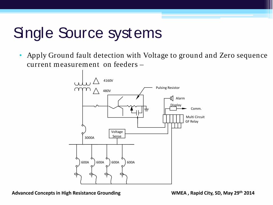
Single Source systems • Apply Ground fault detection with Voltage to ground and Zero sequence
current measurement on feeders –
VoltageSense
Multi CircuitGF Relay
Alarm
600A600A600A600A
4160V
480V
3000A
Pulsing Resistor
DisplayComm.
Advanced Concepts in High Resistance Grounding WMEA , Rapid City, SD, May 29th 2014
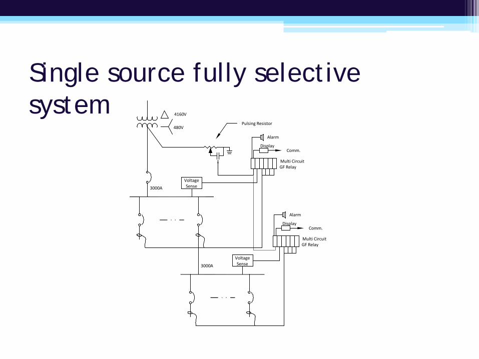
Single source fully selective system
VoltageSense
Multi CircuitGF Relay
Alarm
4160V
480V
3000A
Pulsing Resistor
DisplayComm.
VoltageSense
Multi CircuitGF Relay
Alarm
3000A
DisplayComm.
Multiple sources
• When more than one source is in operation apply resistance grounding so that the fault current does not vary with the number of sources
• Helps in relay settings, keeps fault damage low • Apply grounding at the main bus – Fig 3
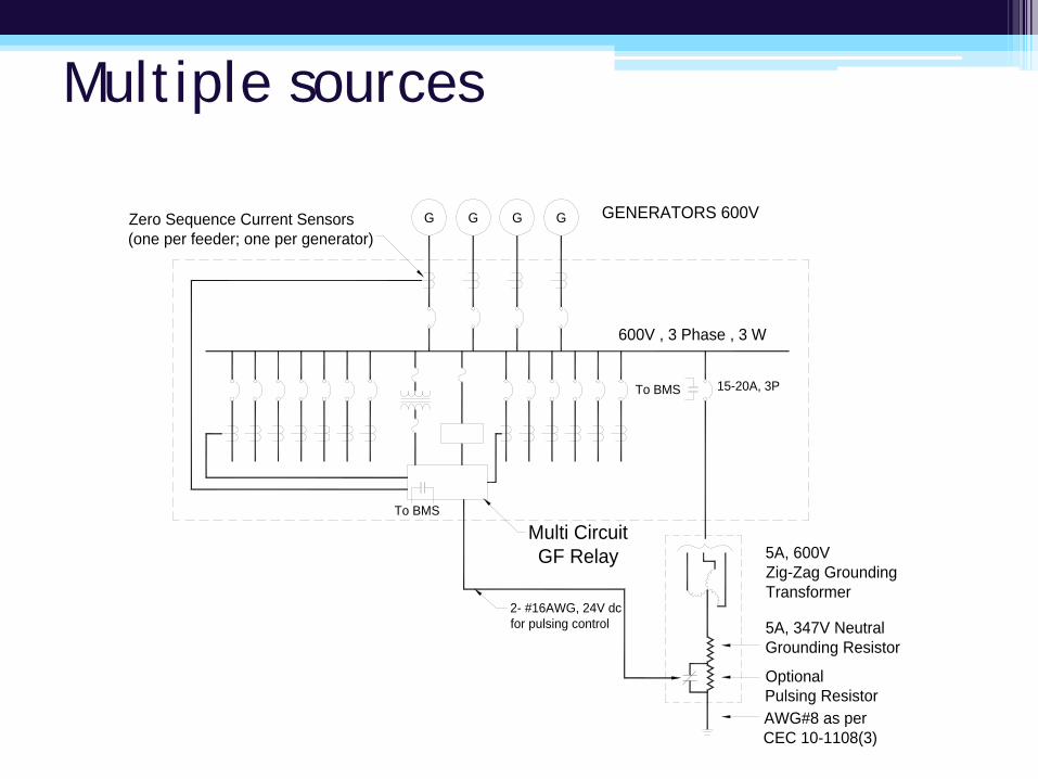
Multiple sources
G GENERATORS 600VG G G
5A, 347V NeutralGrounding Resistor
OptionalPulsing Resistor
To BMS 15-20A, 3P
600V , 3 Phase , 3 W
AWG#8 as perCEC 10-1108(3)
5A, 600VZig-Zag GroundingTransformer
To BMS
2- #16AWG, 24V dcfor pulsing control
Zero Sequence Current Sensors(one per feeder; one per generator)
Multi CircuitGF Relay
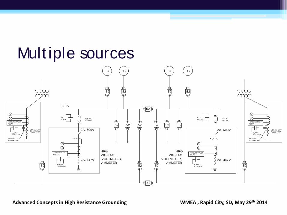
Multiple sources
52
52
G
52
G
52
G
52
G
52 52
52
52 52
5252 52 52
2A, 347V
HRGZIG-ZAGVOLTMETER,AMMETER
ALARMTO SCADA
GROUND FAULTRELAY
2A, 600V
V
A
TOSCADA
15A, 3P100KAIC
52 52
600V
ALARMTO SCADA
GROUND FAULTRELAY
V
A
NGR 2A, 347VPULSE TO 4A
PULSINGCONTACTOR
ALARMTO SCADA
GROUND FAULTRELAY
V
A
NGR 2A, 347VPULSE TO 4A
PULSINGCONTACTOR
2A, 347VALARMTO SCADA
GROUND FAULTRELAY
2A, 600V
V
A
TOSCADA
15A, 3P100KAIC
HRGZIG-ZAG
VOLTMETER,AMMETER
Advanced Concepts in High Resistance Grounding WMEA , Rapid City, SD, May 29th 2014
Low Resistance Grounding
• Used on medium voltage (MV) distribution systems ( 5KV – 36 KV )
• System charging current too large for high resistance grounding or retrofits
• Ground fault current limited to 20– 100 A typically
• Trip on ground fault • Prevents arc flash incident on ground fault
Advanced Concepts in High Resistance Grounding WMEA , Rapid City, SD, May 29th 2014
Low Resistance Grounding
• NGR Sizing Dependent on 3ICO, and Protection Relay Sensitivity
Advanced Concepts in High Resistance Grounding WMEA , Rapid City, SD, May 29th 2014
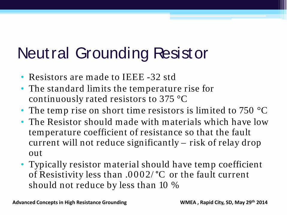
Neutral Grounding Resistor • Resistors are made to IEEE -32 std • The standard limits the temperature rise for
continuously rated resistors to 375 °C • The temp rise on short time resistors is limited to 750 °C • The Resistor should made with materials which have low
temperature coefficient of resistance so that the fault current will not reduce significantly – risk of relay drop out
• Typically resistor material should have temp coefficient of Resistivity less than .0002/°C or the fault current should not reduce by less than 10 %
Advanced Concepts in High Resistance Grounding WMEA , Rapid City, SD, May 29th 2014
Medium voltage Systems
• Only 1 rule is different than for low voltage. ▫ Cable insulation ▫ 133% insulation when fault is on system for upto 1
hour ▫ 173% insulation when fault continues beyond 1
hour
Advanced Concepts in High Resistance Grounding WMEA , Rapid City, SD, May 29th 2014
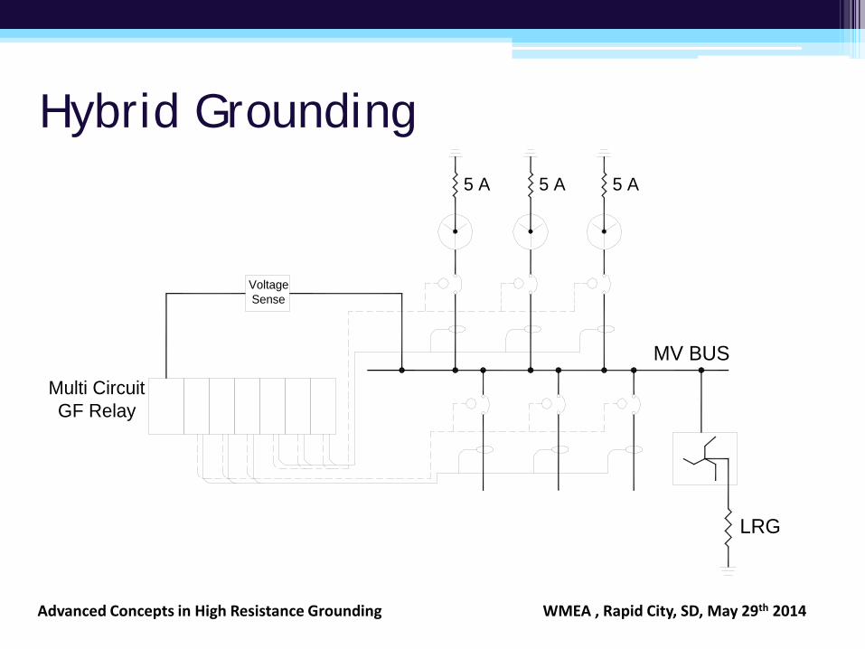
Hybrid Grounding
VoltageSense
Multi CircuitGF Relay
5 A
MV BUS
LRG
5 A 5 A
Advanced Concepts in High Resistance Grounding WMEA , Rapid City, SD, May 29th 2014
Generator grounding • Stator windings in Generators are braced to with
stand 3 phase short circuit current. • On solidly grounded generator the Line to ground
current will be larger than the three phase short circuit current
• Large generators need to impedance grounded because the zero sequence impedance is less than the positive sequence impedance to ensure that the L-G current will be less than 3 phase short circuit current.
Advanced Concepts in High Resistance Grounding WMEA , Rapid City, SD, May 29th 2014
Hybrid grounding of generators
• For generators with MV out put and 10MW and larger size the damage due to a line to ground fault in the stator winding can be minimized and protection provided by hybrid grounding of the generator
Advanced Concepts in High Resistance Grounding WMEA , Rapid City, SD, May 29th 2014
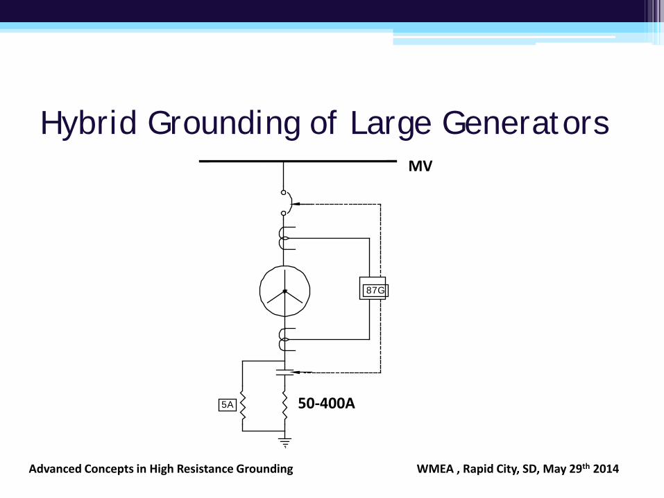
Hybrid Grounding of Large Generators
87G
5A
MV
50-400A
Advanced Concepts in High Resistance Grounding WMEA , Rapid City, SD, May 29th 2014
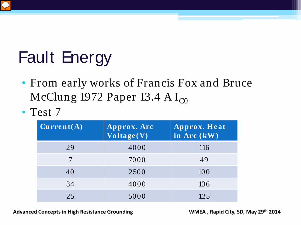
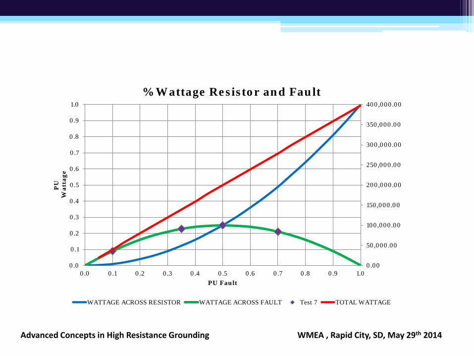
Fault Energy • From early works of Francis Fox and Bruce
McClung 1972 Paper 13.4 A IC0
• Test 7 Current(A) Approx. Arc
Voltage(V) Approx. Heat in Arc (kW)
29 4000 116
7 7000 49
40 2500 100
34 4000 136
25 5000 125
Advanced Concepts in High Resistance Grounding WMEA , Rapid City, SD, May 29th 2014
0.00
50,000.00
100,000.00
150,000.00
200,000.00
250,000.00
300,000.00
350,000.00
400,000.00
0.0
0.1
0.2
0.3
0.4
0.5
0.6
0.7
0.8
0.9
1.0
0.0 0.1 0.2 0.3 0.4 0.5 0.6 0.7 0.8 0.9 1.0
PU
Wat
tage
PU Fault
% Wattage Resistor and Fault
WATTAGE ACROSS RESISTOR WATTAGE ACROSS FAULT Test 7 TOTAL WATTAGE
Advanced Concepts in High Resistance Grounding WMEA , Rapid City, SD, May 29th 2014
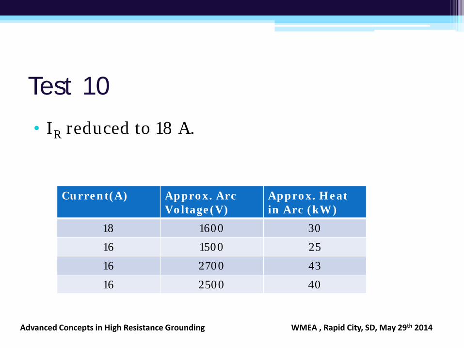
Test 10
• IR reduced to 18 A.
Current(A) Approx. Arc Voltage(V)
Approx. Heat in Arc (kW)
18 1600 30
16 1500 25
16 2700 43
16 2500 40
Advanced Concepts in High Resistance Grounding WMEA , Rapid City, SD, May 29th 2014
0.00
20,000.00
40,000.00
60,000.00
80,000.00
100,000.00
120,000.00
140,000.00
0.0
0.1
0.2
0.3
0.4
0.5
0.6
0.7
0.8
0.9
1.0
0.0 0.1 0.2 0.3 0.4 0.5 0.6 0.7 0.8 0.9 1.0
PU
Wat
tage
PU Fault
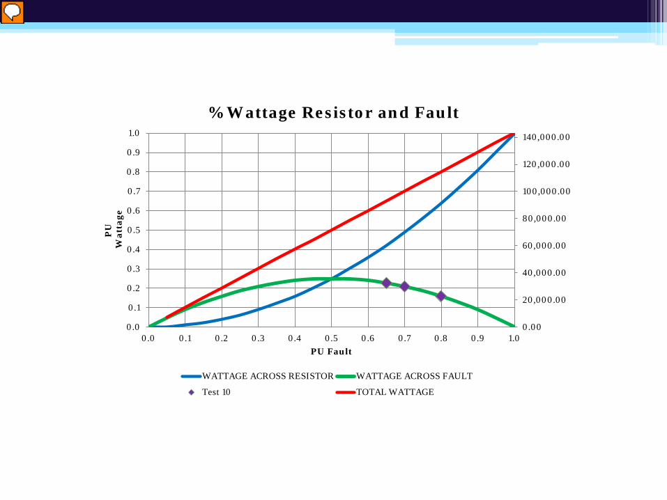
% Wattage Resistor and Fault
WATTAGE ACROSS RESISTOR WATTAGE ACROSS FAULT
Test 10 TOTAL WATTAGE
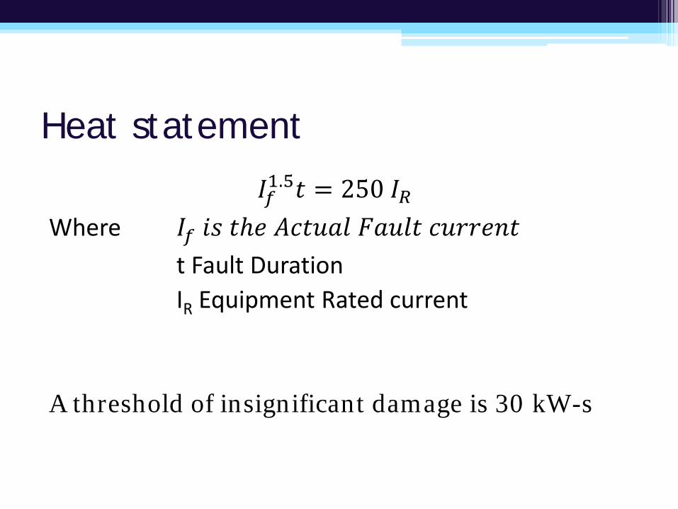
Heat statement
𝐼𝐼𝑓𝑓1.5𝑡𝑡 = 250 𝐼𝐼𝑅𝑅 Where 𝐼𝐼𝑓𝑓 𝑖𝑖𝑖𝑖 𝑡𝑡𝑡𝑡𝑡 𝐴𝐴𝐴𝐴𝑡𝑡𝐴𝐴𝐴𝐴𝐴𝐴 𝐹𝐹𝐴𝐴𝐴𝐴𝐴𝐴𝑡𝑡 𝐴𝐴𝐴𝐴𝑐𝑐𝑐𝑐𝑡𝑡𝑐𝑐𝑡𝑡 t Fault Duration IR Equipment Rated current A threshold of insignificant damage is 30 kW-s
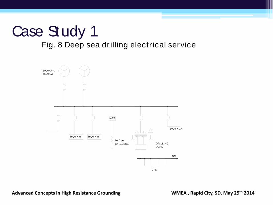
Case Study 1 Fig. 8 Deep sea dr illing electr ical service
8000KVA6500KW
4000 KW 4000 KW
NGT
5A Cont.10A 10SEC DRILLING
LOAD
DC
VFD
8000 KVA
Advanced Concepts in High Resistance Grounding WMEA , Rapid City, SD, May 29th 2014
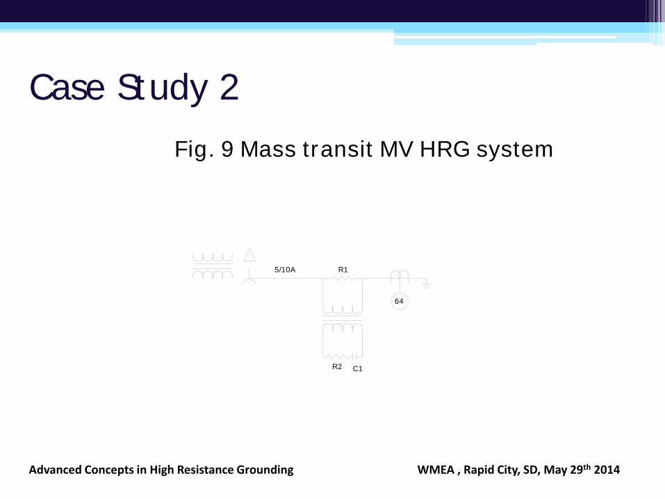
Case Study 2
Fig. 9 Mass transit MV HRG system
C1R2
R15/10A
64
Advanced Concepts in High Resistance Grounding WMEA , Rapid City, SD, May 29th 2014
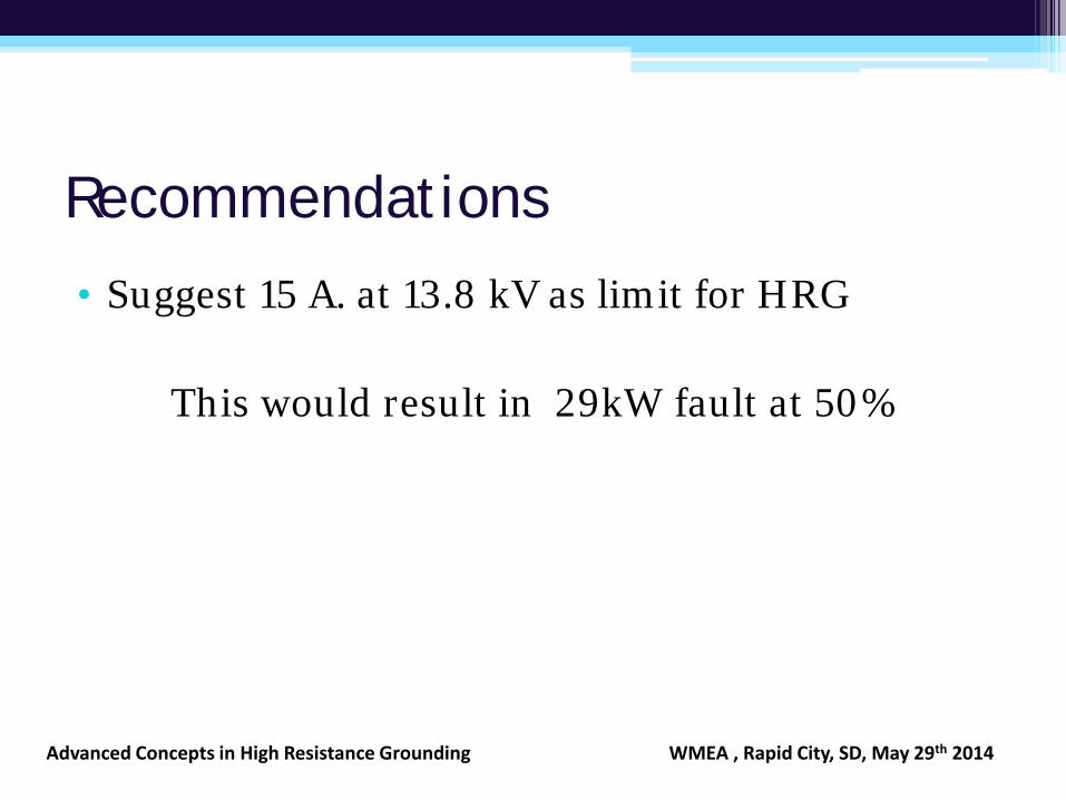
Recommendations
• Suggest 15 A. at 13.8 kV as limit for HRG
This would result in 29kW fault at 50%
Advanced Concepts in High Resistance Grounding WMEA , Rapid City, SD, May 29th 2014
Thank you
• Questions? • Comments?
Advanced Concepts in High Resistance Grounding WMEA , Rapid City, SD, May 29th 2014