adsr envelope generator assembly manual...
TRANSCRIPT

THANK YOU FOR ORDERING ERICA SYNTHS ADSR ENVELOPE GENERATOR KIT!This ADSR envelope generator is another module in Erica Synths DIY Polivoks modules line. If other modules in Erica Synths Polivoks line are updated versions of original designs and use original Russian parts, because they are in sound generation/shaping chain, envelope generator is designed from the scratch. I have made the original Polivoks envelope generator couple of years ago for my rack mount Polivoks clone, but I found it unstable and unpredictable, and, when I tried to use it in eurorack modular, I could not get it working. Therefore together with my friend, musician and engineer Edward D-tech, we decided to develop our own EG that mimics Polivoks Envelope generator, but has much wider range and has unique, unseen before solutions.
TECHNICAL CHARACTERISTICS:
Attack, Decay, Release time 1ms – 5s (modifiable – see trimming page)
Sustain level 0-10V
Power consumption42mA@+12V, 37mA@-12V
ADSR ENVELOPE GENERATOR ASSEMBLY MANUAL
SUSTAIN
DECAY
RELEASE
ATTACK
GATE EG OUT
HARDGATE
TRIGGER
POLIVOKS ADSR
ADSR knobs. Adjust desired ADR time (1ms – 5s) and
Sustain level (0 - +10V)
Loop switch. EG loops in AR mode and Sustain knob biases
the envelope from 0 to +10V. In Loop mode you still can
retrigger the envelope with Gate or Trigger.
Hard Gate switch. Removes gate, and envelope generator
goes into Attack-Decay mode. In this mode Sustain level
knob biases the envelope from 0 to +10V.
Trigger input. Retriggers envelope at any moment. If
nothing is plugged in, it is normalled to gate. Configu-
rable for Active High (standard eurorack) or Active Low
(Korg) gates.
Gate input. Accepts any gate signal (adjustable
threshold). Configurable for Active High (standard
eurorack) or Active Low (Korg) gates.
Output. Get perfect 0 - +10V envelope here

ENVELOPES
+10
+5
0
-5
-10
+10
+5
0
-5
-10
+10
+5
0
-5
-10
+10
+5
0
-5
-10
+10
+5
0
-5
-10
+10
+5
0
-5
-10
Full ADSR envelope, +5V sustain Full ADSR envelope, +8V sustain Full ADSR envelope, +10V sustain
AD envelope with Hard Gate switch off AD envelope with Hard Gate switch off biased to +3,5V using Sustain knob
AR envelope in Loop mode,retriggered with an external trigger.

ORIGINAL POLIVOKS ADSR ENVELOPE GENERATOR SCHEMATICS
NB: POLIVOKS USES NEGATIVE GATE (KEY DOWN –> GATE -12V)

ERICA SYNTHS ADSR ENVELOPE GENERATOR SCHEMATICS

HOW IT WORKS?
GENERALLY, ERICA SYNTHS ENVELOPE GENERATOR CONSISTS OF:
* Input/knob control voltage section
* Control voltage multiplexer
* Slew rate controlled integrator charge/discharge circuit that tracks target level and sensing
* Control logic with gate and trig inputs
* Output
Logic selects with level to track at with rate. This select (2 or 3 bit) is passed to multiplexer that selects two control voltages out of many available. One for tracking rate, the other one - target level. Normaly EG rests in idle state, that tracks idle voltage (normaly 0V) with release rate. As soon as EG is triggered, logic selects next stage for the tracking circuit and it enters the attack stage. During this stage, analog multiplexer sets attack rate and attack voltate to tracking circuit, and voltage on the output rises until it reaches the set level. As soon as the set level is reached, logic advances to the next stage, that is decay/sustain stage. In this stage, tracker
circuit tracks sustain control voltage with the dacay rate for as long as key (gate) is not released. At any time, as soon as key gets released, logic sets release/idle state. In loop mode, logic enters attack stage as soon as release stage is completed.
Trigger and gate inputs are filtered against spike glitches. Tigger input can be fed with gate signal or any signal of any duration, as it also has duration limiting circuit. Gate and trigger inputs can be set to any polarity using jumpers. Selecting active high means that pressing and holding a key on the controlling keyboard produces a more positive pulse relative to idle voltage on the trigger input, and gte stays on higher voltage until the key is released. Active high controls are Roland and Sequential Circuits compatible, while active low setting is for Korg and Moog compatibility. Gate and trigger input levels can be set independantly for compatibility with absolutely any sources. Both inputs have an option for pull-up resistor in case a compati-bility with korg modular analog is needed.
Tracking circuit tracks any set voltage target points from -10V to +10V, with rate control voltage from approx -0.65 to +10V. The higher the rate control voltage, the faster it tracks the target voltage. As analog multiplexer is not fit to switch bipolar 20Vp-p signals, control voltages are scaled before and aster the ic.
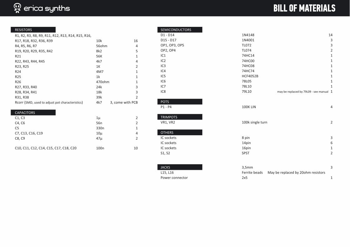
BILL OF MATERIALS

step➊First let’s configure gate and trigger for Active High (Roland, eurorack, etc.) or Active Low (Korg) response! Most probably you will use Active High gate, therefore use wire jumpers to jump AH connectors.
step➋
Now we need to deform characteristics of potentiometers. Use SMD resistors and solder them across Attack, Decay and Release potentiom-eters as shown on pictures below! First apply some solder on one area of the pot, then solder the SMD resistor here, and finally solder another end of the resistor.
BUILDING INSTRUCTIONS

step➌Solder all resistors
step➍Solder diodes and ferrite beads
BUILDING INSTRUCTIONS

BUILDING INSTRUCTIONS
step➎
Solder capacitors, mind polarity of electrolytic capacitors
step➏Solder IC sockets

BUILDING INSTRUCTIONS
step➐aYou may have trouble with finding 79L10 – 10V negative voltage regula-tor. Luckily we have a solution! Take 79L09, cut its GND pin off close to the case and replace it with 680ohm resistor! Then solder the IC on PCB as shown on picture below!
step➐Solder trimpots and voltage regulator ICs
BUILDING INSTRUCTIONS
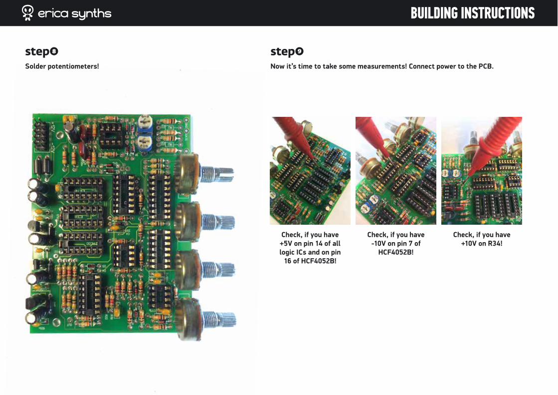
step➒
Now it’s time to take some measurements! Connect power to the PCB.
step➑
Solder potentiometers!
Check, if you have +5V on pin 14 of all logic ICs and on pin
16 of HCF4052B!
Check, if you have -10V on pin 7 of
HCF4052B!
Check, if you have +10V on R34!

BUILDING INSTRUCTIONS
step11
Insert Jacks and Switches in the panel, solder GND lugs. Do not forget to normal switching lug of the Trigger In jack to the connecting lug of the Gate in (yellow wire)!
step10
Insert all ICs!

BUILDING INSTRUCTIONS
step13
Insert the PCB and fix it via pot nuts! Complete wiring! Do not forget to connect GND to the PCB!
step12
Solder ~30mm wire to Gate and Trigger inputs on the PCB.

SUSTAIN
DECAY
RELEASE
ATTACK
GATE EG OUT
HARDGATE
TRIGGER
POLIVOKS ADSR
BUILDING INSTRUCTIONS
step14
Install pot knobs! Congratulations! You have completed Erica Synths ADSR envelope generator!
TRIMMING AND TROUBLESHOOTING
ster supplying power to the EG module, connect the voltmeter to the washers of trimming resistors VR1 and VR2 and check, if they allow tuning from -10V to +10v. If not, there is something wrong with the assembly or power supplies. Set both inputs to +2.5V for most general compatibility: at this setting, trig and gate control voltages below this voltage will be considered low level, and when above - high. This allows EG to work with +4v, +5v logic and 10V control signals, with inactive state anywhere below 2V down to -10V. If your control source has different output voltages, feel free to set it anywhere in the middle of its span. Say, if your controller outputs -7 when idle and -4 when active, set the respective trim resistor to -5.5V. Basically, you have to achieve the situation, when both Gate and Trigger signals affect the envelope.
If you wish to modify ADR time, feel free to experiment with value of C3!
WHAT TO DO IF EG DOESN'T SEEM TO BE WORKING.
Ensure that input signals that you supply to the module are good and knobs are set to meaningful values. Check external voltage supplies and onboard -10V and +10V as well as +5V LDOs. Tune the gate and trig input threshold pots. Using an oscilloscope, check if trig and gate signals from controller appear on respective schmitt trigger (74HC14) gate inputs and outputs. If so far all seems well, check to see if rotating knobs produce control voltages on the respective multiplexer input pins. When in idle state, analog multiplexer outputs should match the idle voltage and release knob voltages on inputs. If they don't, check if multiplexer selection signals are all low (when in idle). If they are not, there is something wrong with the control logic or control signals. Check if low voltage (slowest setting) for the rate knobs is somewhere around -0.65V. If not, there may be something wrong with the reference source circuit (OP1.1 and R1, D1, C1, R2, R3) that supplies this voltage. Changing release rate in idle state should change voltages at the diodes D2 and D3. Voltages from OP1.2 and OP3.1 should change in a mirror fashion, accordingly to the set rate. At the slowest rate cathode of D3 should be around -0.65V while anode of D2 should be around +0.65V. Increasing the rate speed should increase voltage on the cathode of D3 and decrease in on anode of D2.
User manual by Girts Ozolins@Erica Synths. Design by Edgars Rasins. Copying, distribution or any commercial use of schematics, technical solutions and/or parts of the manual in any way is prohibited and needs the written permission by Erica Synths. Specifications are subject to change without notice.