adsl modem vpn (virtual private network) ethernet … · ethernet gateway remote access server ......
TRANSCRIPT
eWON 4104™
ADSL ModemVPN (Virtual Private Network)
Ethernet GatewayRemote Access Server (RAS)
Programmable Industrial Router (PIR)
Installation GuideRev. 1.1
CoolInternet
TelecontrolSolutions
eWON4104™Installation Guide ver 1.1
1 Product description .......................................................................................................... 4 1.1 Introduction................................................................................................................. 4 1.2 General specification of the hardware platform.......................................................... 4 1.3 Functions of the eWON4104™ .................................................................................. 4 1.3.1 General ................................................................................................................... 4 1.3.2 Virtual Private Network ......................................................................................... 4 1.3.3 Remote Access Server functions ........................................................................... 4 1.3.4 Ethernet to Serial Gateways................................................................................... 5 1.3.5 Programmable Industrial Router functions ............................................................ 5 1.3.6 Datalogger.............................................................................................................. 5 1.4 Typical applications .................................................................................................... 5 1.5 Part Numbers and internal options.............................................................................. 6
2 eWON technical documentation ...................................................................................... 7
3 Housing and markings ..................................................................................................... 8 3.1 Housing Interfaces ...................................................................................................... 8 3.2 Markings ..................................................................................................................... 9 3.3 Applicable directives, standards and compliance ....................................................... 9 3.4 Equipment information and versions .......................................................................... 10 3.5 Mechanical outline...................................................................................................... 11 3.6 Mounting and environmental conditions .................................................................... 12 3.7 Preparing the installation ............................................................................................ 12 3.8 Specification for external power supply selection ...................................................... 12 3.8.1 Auto fuse ................................................................................................................ 13
4 Front panel control LEDs................................................................................................. 13
5 Specifications of communication interfaces and I/Os ..................................................... 14 5.1 Ethernet Ports.............................................................................................................. 14 5.2 Embedded ADSL Modem........................................................................................... 14 5.3 Embedded PSTN Modem (optional) .......................................................................... 14 5.4 Embedded quad band GSM/GPRS Modem (optional) ............................................... 15 5.5 Embedded quad band EDGE Modem (optional) ........................................................ 15 5.5.1 SIM-card installation (EDGE and GPRS modem) ................................................ 15 5.6 Embedded ISDN Modem (optional) ........................................................................... 16 5.7 Configurable serial port .............................................................................................. 17 5.8 MPI port ..................................................................................................................... 18 5.9 Digital input ................................................................................................................ 18 5.10 Digital output ............................................................................................................ 19
6 IP parameters configuration ............................................................................................. 20 6.1 Resets .......................................................................................................................... 21 6.1.1 User Reset .............................................................................................................. 21 6.1.2 Factory Reset ......................................................................................................... 21
7 Technical support............................................................................................................. 22
8 Appendix: Pinouts and connections................................................................................. 22 8.1 Power Supply .............................................................................................................. 22 8.2 Ethernet ....................................................................................................................... 23 8.2.1 Ethernet LAN......................................................................................................... 23 8.2.2 Direct connection ................................................................................................... 24
page 2 of 3

eWON4104™Installation Guide ver 1.1
8.2.3 Connection over hub/router ................................................................................... 25 8.3 RJ45 connector............................................................................................................ 26 8.4 Input/Outputs .............................................................................................................. 27 8.5 Serial Port.................................................................................................................... 28 8.6 MPI port ...................................................................................................................... 29 8.7 ADSL / PSTN / ISDN phone line connector .............................................................. 30 8.8 Antenna connector ...................................................................................................... 30
page 3 of 3
eWON4104™Installation Guide ver 1.1
1 Product description
1.1 IntroductionThe eWON4104™ is the Industrial LAN/ADSL Router version of a complete range of Ethernet/Internet gateways also known as “Programmable Industrial Routers” (PIR). See our web site http://www.ewon.biz to get further information about the eWON range. The eWON is a terminal that enables access to technical data, whatever their format is. It is configurable by web pages. It is secure because it meets the toughest industrial standards and has restricted access features (required in open networks). The eWON4104™ can optionally embed a modem (GSM/GPRS/EDGE/PSTN/ISDN).
The eWON range supports the TCP/IP and PPP protocols. This brings you all the benefits of an universally recognized standard network. It also allows you to use popular software tools like Internet Explorer, FTP client, SNMP Manager, Mail Recipient … and so to reduce significantly your costs (implementation and ownership).
1.2 General specification of the hardware platform• Processor ARM clocked @ 75Mhz, 16Mb SDRAM, 32Mb Flash• Backed up real time clock (RTC) with 24 Hours autonomy • Battery with 10 years autonomy (for RTC)• External power supply 12-24 VDC +/- 20%, consumption: 10W max• 1 ADSL modem• 1 Ethernet switch with 4 ports 10/100Mb BaseTx• 1 Serial port isolated configurable in RS232/RS422/RS485
OR 1 MPI port (up to 12 Mbits/sec)
• 1 digital input (DI)• 1 digital output (DO)• DIN rail mounting compliant with EN50022 (latch)• Environmental conditions (operating):
Ambient T°: from 0°C to +50°CHumidity: from 0 to 80% non condensing
1.3 Functions of the eWON4104™ 1.3.1 General
• Ethernet Gateway to serial protocols• Data acquisition• Web server – fully customizable web pages• viewON compatible (optional)• Programmable by BASIC scripts• Alarm management• Report generation
1.3.2 Virtual Private Network
• Allow to build your own Virtual Private Network (VPN) thanks to OpenVPN technology
1.3.3 Remote Access Server functions
• Remote Access Server (RAS) and TCP/IP Server• PAP/CHAP Authentication• Login/password• Remote network access• User access control• Security: NAT, IP filtering• Conventional and internet callback
page 4 of 30
eWON4104™Installation Guide ver 1.1
1.3.4 Ethernet to Serial Gateways
• MODBUS TCP to MODBUS RTU• XIP to UNITELWAY• EtherNet/IP™ to DF1• FINS TCP to FINS Hostlink• ISOTCP to PPI (optionnaly MPI)• VCOM / ASCII
1.3.5 Programmable Industrial Router functions
• Automatic routing of protocols• Programmable routing from I/O and Tag names (BASIC)
1.3.6 Datalogger
• • Internal cyclic database - up to 139264 points• • Export of data in binary or text format, by FTP or as an Email attachment
1.4 Typical applications• Alarm management• Sending alarms by network, phone, Email and/or SMS • Remote measurements, loop back, control and monitoring• Predictive and operational maintenance• Diagnosis and machinery status control• Stock and vessel level monitoring• Process and machinery activity logs• Commissioning support• Remote programming• Interface for Application Service Providers (ASP)• Datalogging
page 5 of 30
eWON4104™Installation Guide ver 1.1
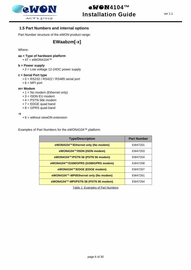
1.5 Part Numbers and internal optionsPart Number structure of the eWON product range:
EWaabzm[-x]Where:
aa = Type of hardware platform• 47 = eWON4104™
b = Power supply• 2 = Low voltage 12-24DC power supply
z = Serial Port type• 0 = RS232 / RS422 / RS485 serial port• 6 = MPI port
m= Modem• 1 = No modem (Ethernet only)• 3 = ISDN EU modem• 4 = PSTN 56k modem• 7 = EDGE quad band• 8 = GPRS quad band
-x• 6 = without viewON extension
Examples of Part Numbers for the eWON4104™ platform:
Type/Description Part Number
eWON4104™/Ethernet only (No modem) EW47201
eWON4104™/ISDN (ISDN modem) EW47203
eWON4104™/PSTN 56 (PSTN 56 modem) EW47204
eWON4104™/GSM/GPRS (GSM/GPRS modem) EW47208
eWON4104™/EDGE (EDGE modem) EW47207
eWON4104™-MPI/Ethernet only (No modem) EW47261
eWON4104™-MPI/PSTN 56 (PSTN 56 modem) EW47264
Table 1: Examples of Part Numbers
page 6 of 30
eWON4104™Installation Guide ver 1.1
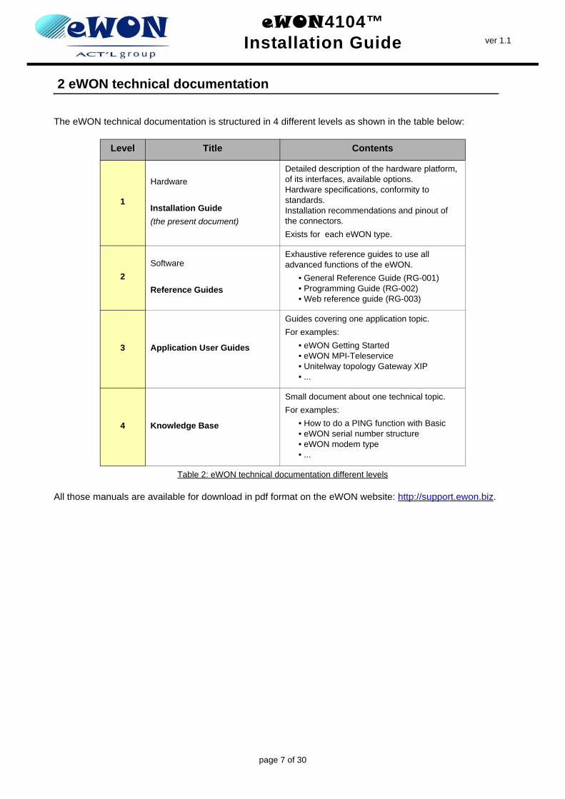
2 eWON technical documentation
The eWON technical documentation is structured in 4 different levels as shown in the table below:
All those manuals are available for download in pdf format on the eWON website: http://support.ewon.biz.
Level Title Contents
1
Hardware
Installation Guide(the present document)
Detailed description of the hardware platform, of its interfaces, available options. Hardware specifications, conformity to standards. Installation recommendations and pinout of the connectors.Exists for each eWON type.
2Software
Reference Guides
Exhaustive reference guides to use all advanced functions of the eWON.
• General Reference Guide (RG-001)• Programming Guide (RG-002)• Web reference guide (RG-003)
3 Application User Guides
Guides covering one application topic.For examples:
• eWON Getting Started• eWON MPI-Teleservice• Unitelway topology Gateway XIP• ...
4 Knowledge Base
Small document about one technical topic.For examples:
• How to do a PING function with Basic• eWON serial number structure• eWON modem type• ...
Table 2: eWON technical documentation different levels
page 7 of 30
eWON4104™Installation Guide ver 1.1
3 Housing and markings
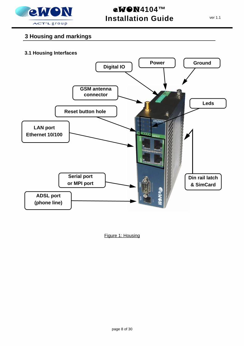
3.1 Housing Interfaces
Figure 1: Housing
LAN portEthernet 10/100
ADSL port(phone line)
Reset button hole
Serial portor MPI port
Digital IOPower Ground
Din rail latch& SimCard
GSM antenna connector
Leds
page 8 of 30
eWON4104™Installation Guide ver 1.1
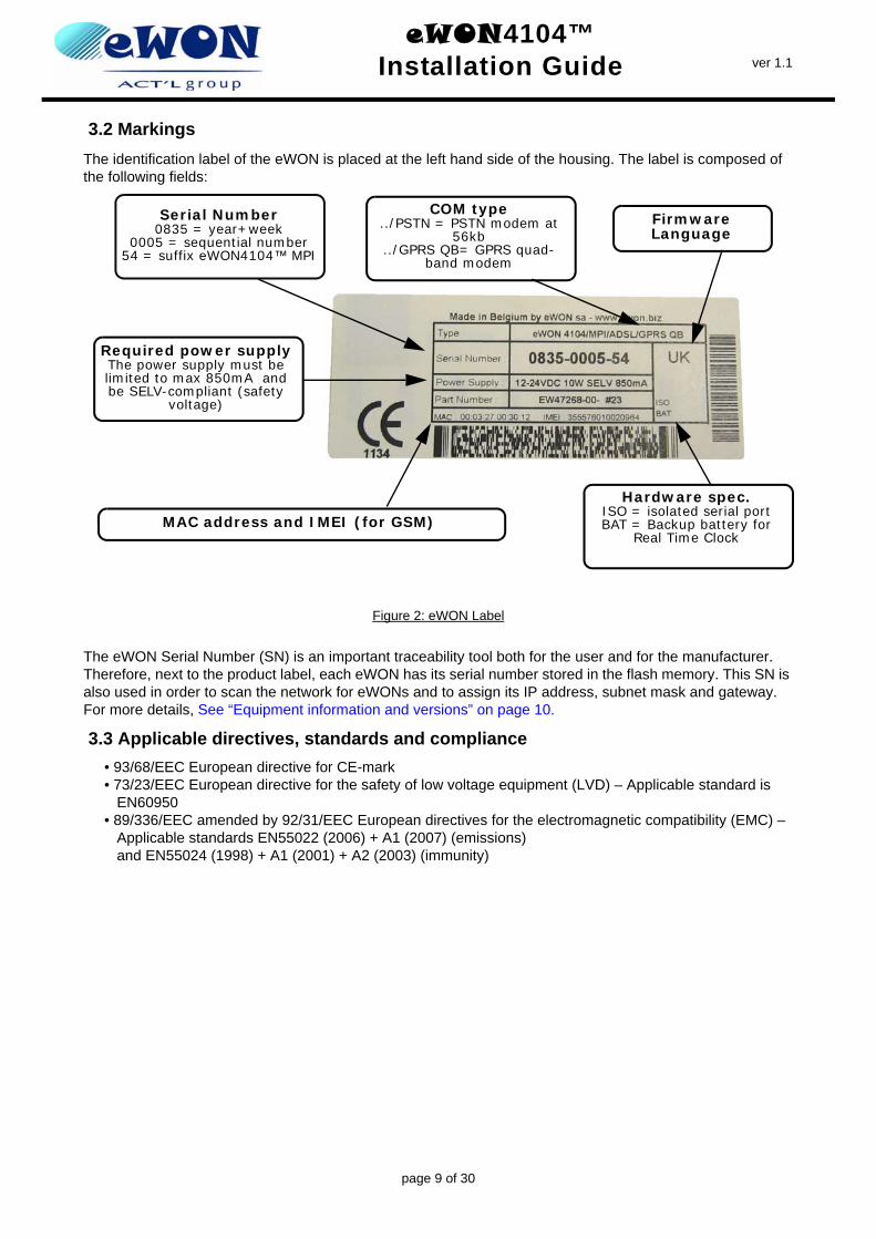
3.2 MarkingsThe identification label of the eWON is placed at the left hand side of the housing. The label is composed of the following fields:
Figure 2: eWON Label
The eWON Serial Number (SN) is an important traceability tool both for the user and for the manufacturer. Therefore, next to the product label, each eWON has its serial number stored in the flash memory. This SN is also used in order to scan the network for eWONs and to assign its IP address, subnet mask and gateway. For more details, See “Equipment information and versions” on page 10.
3.3 Applicable directives, standards and compliance• 93/68/EEC European directive for CE-mark • 73/23/EEC European directive for the safety of low voltage equipment (LVD) – Applicable standard is
EN60950• 89/336/EEC amended by 92/31/EEC European directives for the electromagnetic compatibility (EMC) –
Applicable standards EN55022 (2006) + A1 (2007) (emissions) and EN55024 (1998) + A1 (2001) + A2 (2003) (immunity)
Serial Number0835 = year+week
0005 = sequential number54 = suffix eWON4104™ MPI
COM type../PSTN = PSTN modem at
56kb../GPRS QB= GPRS quad-
band modem
Required power supplyThe power supply must be limited to max 850mA and be SELV-compliant (safety
voltage)
MAC address and IMEI (for GSM)
FirmwareLanguage
Hardware spec.ISO = isolated serial portBAT = Backup battery for
Real Time Clock
page 9 of 30
eWON4104™Installation Guide ver 1.1
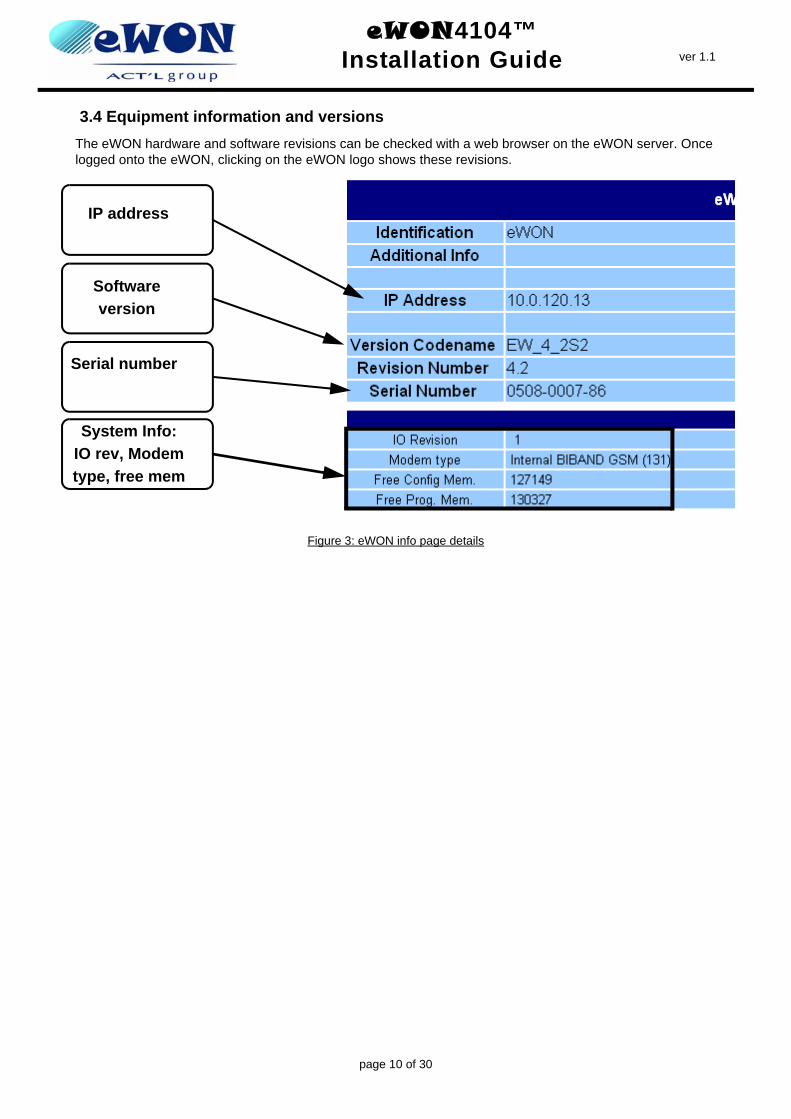
3.4 Equipment information and versionsThe eWON hardware and software revisions can be checked with a web browser on the eWON server. Once logged onto the eWON, clicking on the eWON logo shows these revisions.
Figure 3: eWON info page details
IP address
Software version
Serial number
System Info:IO rev, Modem type, free mem
page 10 of 30
eWON4104™Installation Guide ver 1.1
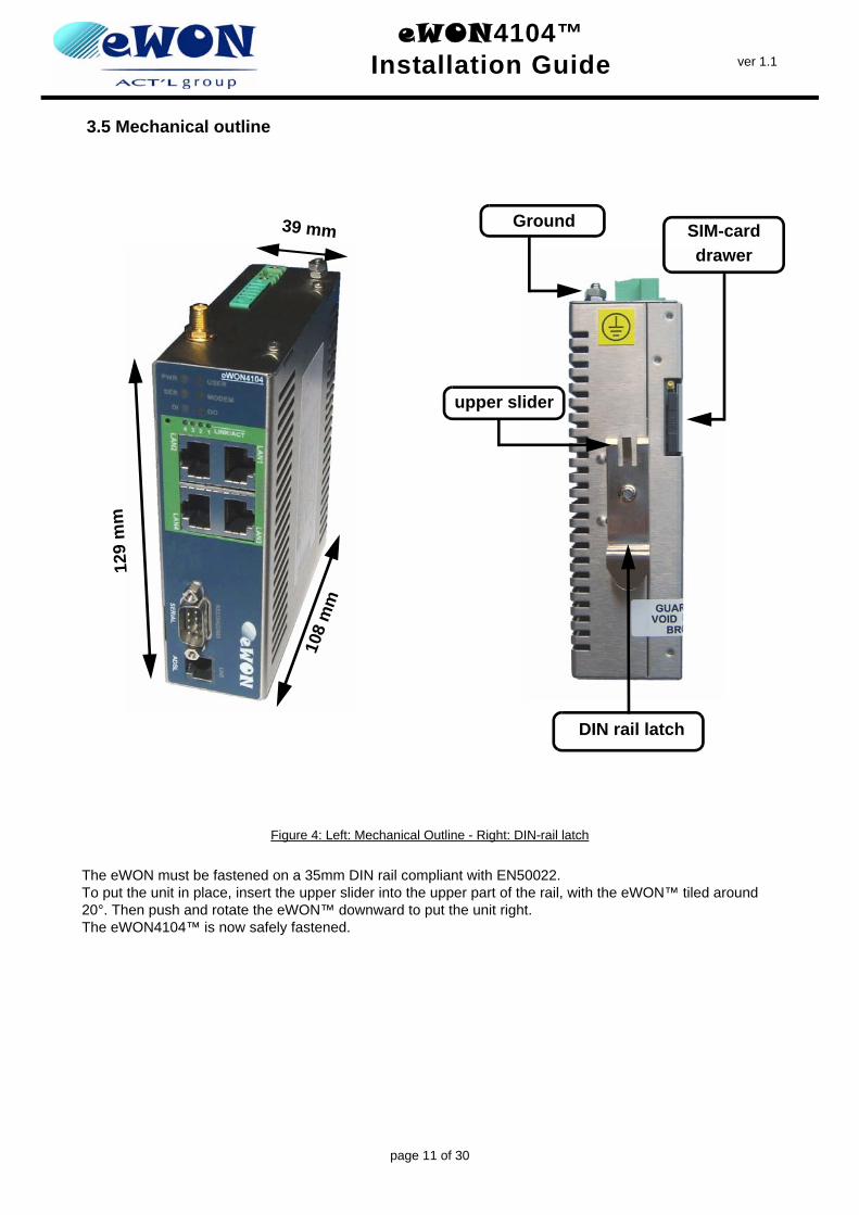
3.5 Mechanical outline
Figure 4: Left: Mechanical Outline - Right: DIN-rail latch
The eWON must be fastened on a 35mm DIN rail compliant with EN50022.To put the unit in place, insert the upper slider into the upper part of the rail, with the eWON™ tiled around 20°. Then push and rotate the eWON™ downward to put the unit right. The eWON4104™ is now safely fastened.
39 mm
129
mm
108
mm
Ground
DIN rail latch
SIM-carddrawer
upper slider
page 11 of 30
eWON4104™Installation Guide ver 1.1
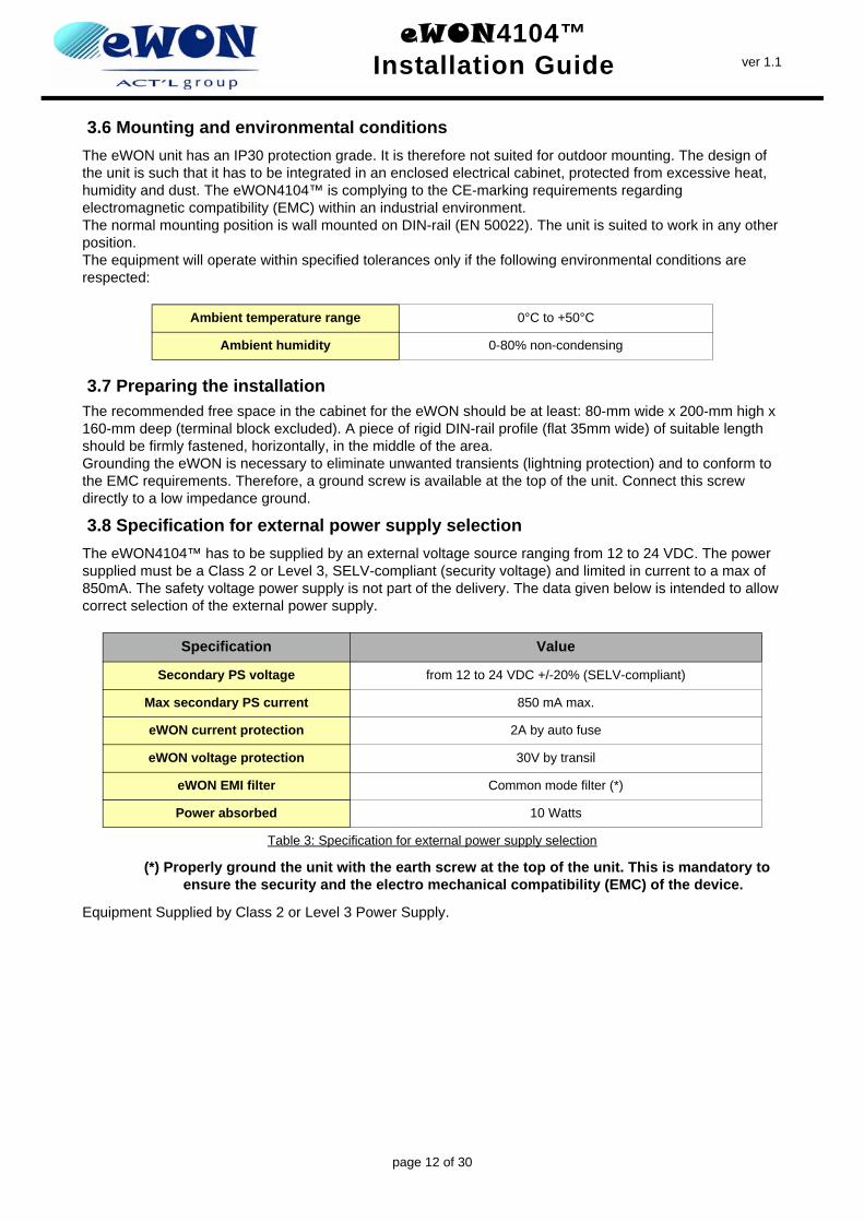
3.6 Mounting and environmental conditionsThe eWON unit has an IP30 protection grade. It is therefore not suited for outdoor mounting. The design of the unit is such that it has to be integrated in an enclosed electrical cabinet, protected from excessive heat, humidity and dust. The eWON4104™ is complying to the CE-marking requirements regarding electromagnetic compatibility (EMC) within an industrial environment.The normal mounting position is wall mounted on DIN-rail (EN 50022). The unit is suited to work in any other position.The equipment will operate within specified tolerances only if the following environmental conditions are respected:
3.7 Preparing the installationThe recommended free space in the cabinet for the eWON should be at least: 80-mm wide x 200-mm high x 160-mm deep (terminal block excluded). A piece of rigid DIN-rail profile (flat 35mm wide) of suitable length should be firmly fastened, horizontally, in the middle of the area.Grounding the eWON is necessary to eliminate unwanted transients (lightning protection) and to conform to the EMC requirements. Therefore, a ground screw is available at the top of the unit. Connect this screw directly to a low impedance ground.
3.8 Specification for external power supply selectionThe eWON4104™ has to be supplied by an external voltage source ranging from 12 to 24 VDC. The power supplied must be a Class 2 or Level 3, SELV-compliant (security voltage) and limited in current to a max of 850mA. The safety voltage power supply is not part of the delivery. The data given below is intended to allow correct selection of the external power supply.
(*) Properly ground the unit with the earth screw at the top of the unit. This is mandatory to ensure the security and the electro mechanical compatibility (EMC) of the device.
Equipment Supplied by Class 2 or Level 3 Power Supply.
Ambient temperature range 0°C to +50°C
Ambient humidity 0-80% non-condensing
Specification Value
Secondary PS voltage from 12 to 24 VDC +/-20% (SELV-compliant)
Max secondary PS current 850 mA max.
eWON current protection 2A by auto fuse
eWON voltage protection 30V by transil
eWON EMI filter Common mode filter (*)
Power absorbed 10 Watts
Table 3: Specification for external power supply selection
page 12 of 30
eWON4104™Installation Guide ver 1.1
3.8.1 Auto fuse
An auto fuse placed just after the power input protects the eWON devices against short circuits. This component returns by itself to its normal state when the short circuit has disappeared and after the component has been cooling down. Would this fuse happen to operate, please check the device for presence of loose metal parts inside likely to generate a short circuit. If the problem recurs even after such a verification, then return the device to the vendor for further investigation.
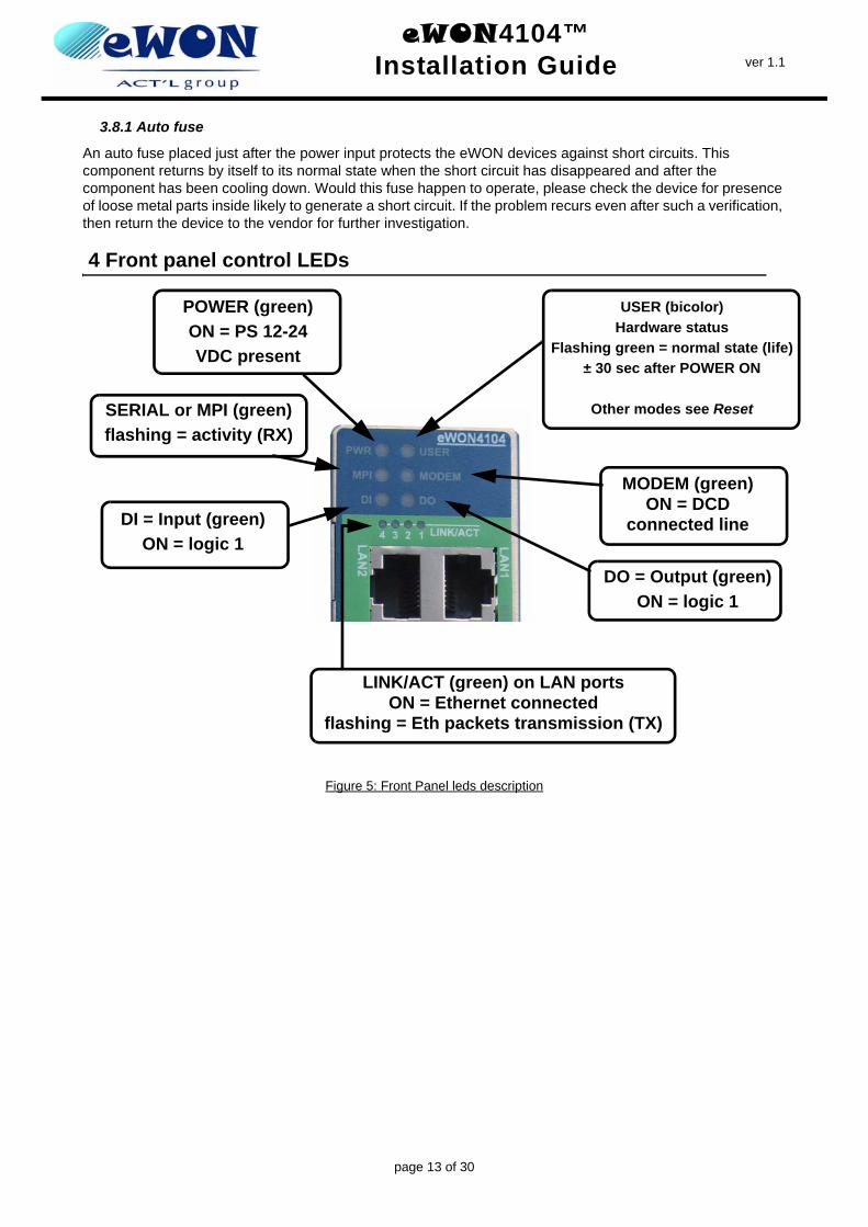
4 Front panel control LEDs
Figure 5: Front Panel leds description
POWER (green) ON = PS 12-24 VDC present
SERIAL or MPI (green) flashing = activity (RX)
DI = Input (green)ON = logic 1
MODEM (green)ON = DCD
connected line
USER (bicolor) Hardware status
Flashing green = normal state (life)± 30 sec after POWER ON
Other modes see Reset
DO = Output (green)ON = logic 1
LINK/ACT (green) on LAN portsON = Ethernet connected
flashing = Eth packets transmission (TX)
page 13 of 30
eWON4104™Installation Guide ver 1.1
5 Specifications of communication interfaces and I/Os
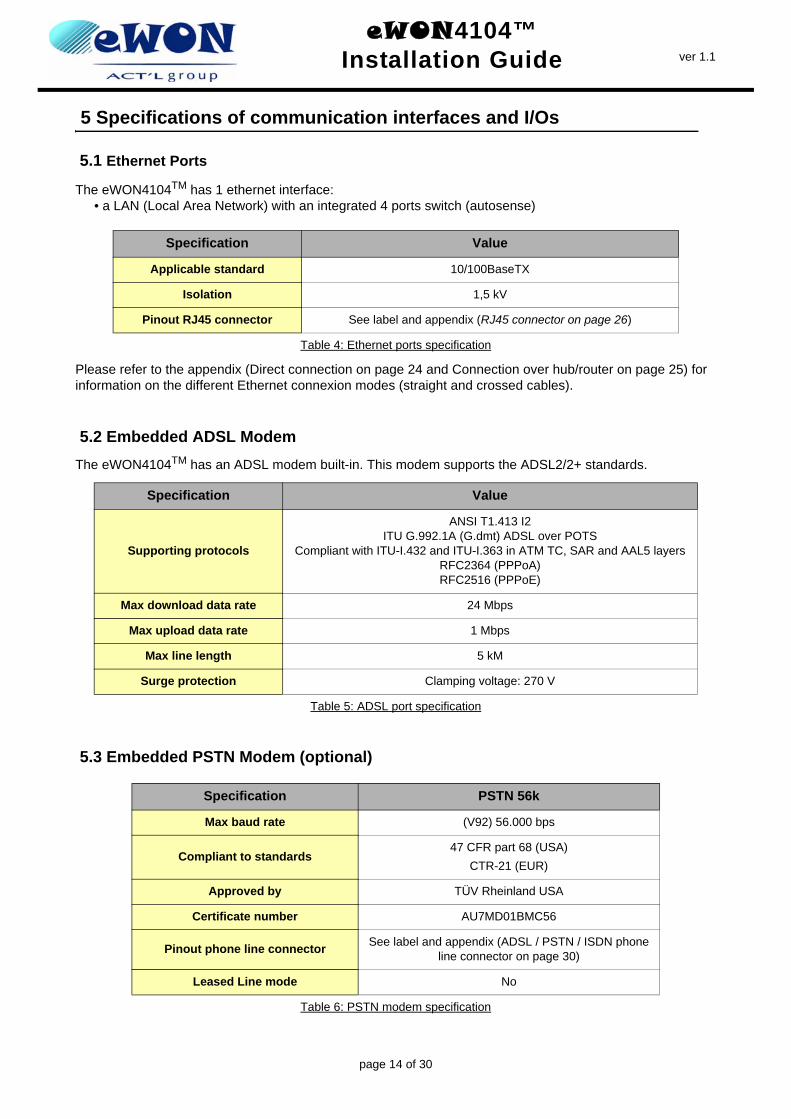
5.1 Ethernet Ports
The eWON4104TM has 1 ethernet interface:• a LAN (Local Area Network) with an integrated 4 ports switch (autosense)
Please refer to the appendix (Direct connection on page 24 and Connection over hub/router on page 25) for information on the different Ethernet connexion modes (straight and crossed cables).
5.2 Embedded ADSL ModemThe eWON4104TM has an ADSL modem built-in. This modem supports the ADSL2/2+ standards.
5.3 Embedded PSTN Modem (optional)
Specification Value
Applicable standard 10/100BaseTX
Isolation 1,5 kV
Pinout RJ45 connector See label and appendix (RJ45 connector on page 26)
Table 4: Ethernet ports specification
Specification Value
Supporting protocols
ANSI T1.413 I2ITU G.992.1A (G.dmt) ADSL over POTS
Compliant with ITU-I.432 and ITU-I.363 in ATM TC, SAR and AAL5 layersRFC2364 (PPPoA)RFC2516 (PPPoE)
Max download data rate 24 Mbps
Max upload data rate 1 Mbps
Max line length 5 kM
Surge protection Clamping voltage: 270 V
Table 5: ADSL port specification
Specification PSTN 56k
Max baud rate (V92) 56.000 bps
Compliant to standards47 CFR part 68 (USA)
CTR-21 (EUR)
Approved by TÜV Rheinland USA
Certificate number AU7MD01BMC56
Pinout phone line connector See label and appendix (ADSL / PSTN / ISDN phone line connector on page 30)
Leased Line mode No
Table 6: PSTN modem specification
page 14 of 30
eWON4104™Installation Guide ver 1.1
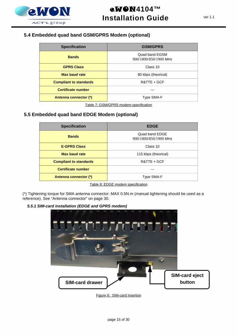
5.4 Embedded quad band GSM/GPRS Modem (optional)
5.5 Embedded quad band EDGE Modem (optional)
(*) Tightening torque for SMA antenna connector: MAX 0.5N.m (manual tightening should be used as a reference). See “Antenna connector” on page 30.
5.5.1 SIM-card installation (EDGE and GPRS modem)
Figure 6: SIM-card insertion
Specification GSM/GPRS
Bands Quad band EGSM900/1800/850/1900 MHz
GPRS Class Class 10
Max baud rate 80 kbps (theorical)
Compliant to standards R&TTE + GCF
Certificate number ---
Antenna connector (*) Type SMA-F
Table 7: GSM/GPRS modem specification
Specification EDGE
Bands Quad band EDGE900/1800/850/1900 MHz
E-GPRS Class Class 10
Max baud rate 115 kbps (theorical)
Compliant to standards R&TTE + GCF
Certificate number ---
Antenna connector (*) Type SMA-F
Table 8: EDGE modem specification
SIM-card eject buttonSIM-card drawer
page 15 of 30
eWON4104™Installation Guide ver 1.1
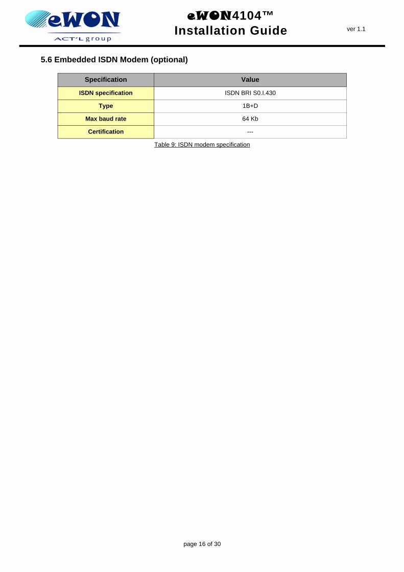
5.6 Embedded ISDN Modem (optional)
Specification Value
ISDN specification ISDN BRI S0.I.430
Type 1B+D
Max baud rate 64 Kb
Certification ---
Table 9: ISDN modem specification
page 16 of 30
eWON4104™Installation Guide ver 1.1
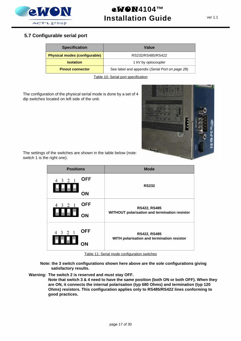
5.7 Configurable serial port
The configuration of the physical serial mode is done by a set of 4 dip switches located on left side of the unit.
The settings of the switches are shown in the table below (note: switch 1 is the right one).
Note: the 3 switch configurations shown here above are the sole configurations giving satisfactory results.
Warning: The switch 2 is reserved and must stay OFF. Note that switch 3 & 4 need to have the same position (both ON or both OFF). When they are ON, it connects the internal polarisation (typ 680 Ohms) and termination (typ 120 Ohms) resistors. This configuration applies only to RS485/RS422 lines conforming to good practices.
Specification Value
Physical modes (configurable) RS232/RS485/RS422
Isolation 1 kV by optocoupler
Pinout connector See label and appendix (Serial Port on page 28)
Table 10: Serial port specification
Positions Mode
RS232
RS422, RS485WITHOUT polarisation and termination resistor
RS422, RS485WITH polarisation and termination resistor
Table 11: Serial mode configuration switches
page 17 of 30
eWON4104™Installation Guide ver 1.1
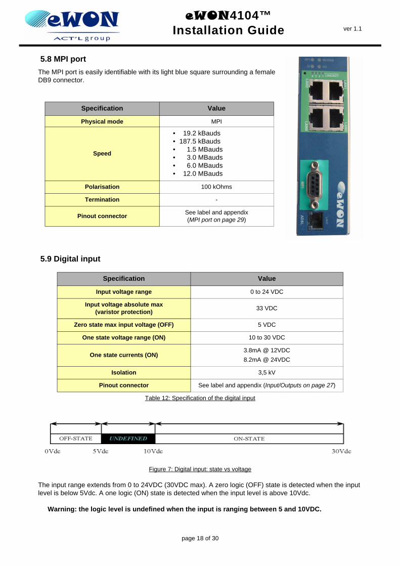
5.8 MPI port The MPI port is easily identifiable with its light blue square surrounding a female DB9 connector.
5.9 Digital input
Figure 7: Digital input: state vs voltage
The input range extends from 0 to 24VDC (30VDC max). A zero logic (OFF) state is detected when the input level is below 5Vdc. A one logic (ON) state is detected when the input level is above 10Vdc.
Warning: the logic level is undefined when the input is ranging between 5 and 10VDC.
Specification Value
Physical mode MPI
Speed
• 19.2 kBauds• 187.5 kBauds• 1.5 MBauds• 3.0 MBauds• 6.0 MBauds• 12.0 MBauds
Polarisation 100 kOhms
Termination -
Pinout connector See label and appendix(MPI port on page 29)
Specification Value
Input voltage range 0 to 24 VDC
Input voltage absolute max(varistor protection) 33 VDC
Zero state max input voltage (OFF) 5 VDC
One state voltage range (ON) 10 to 30 VDC
One state currents (ON)3.8mA @ 12VDC8.2mA @ 24VDC
Isolation 3,5 kV
Pinout connector See label and appendix (Input/Outputs on page 27)
Table 12: Specification of the digital input
page 18 of 30
eWON4104™Installation Guide ver 1.1
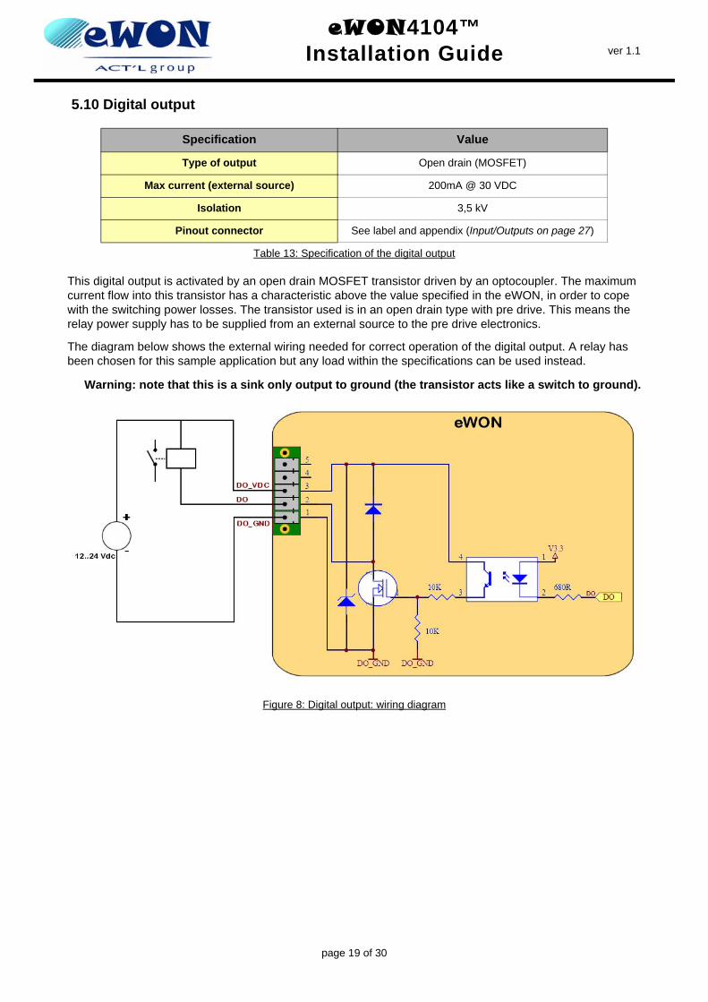
5.10 Digital output
This digital output is activated by an open drain MOSFET transistor driven by an optocoupler. The maximum current flow into this transistor has a characteristic above the value specified in the eWON, in order to cope with the switching power losses. The transistor used is in an open drain type with pre drive. This means the relay power supply has to be supplied from an external source to the pre drive electronics.
The diagram below shows the external wiring needed for correct operation of the digital output. A relay has been chosen for this sample application but any load within the specifications can be used instead.
Warning: note that this is a sink only output to ground (the transistor acts like a switch to ground).
Figure 8: Digital output: wiring diagram
Specification Value
Type of output Open drain (MOSFET)
Max current (external source) 200mA @ 30 VDC
Isolation 3,5 kV
Pinout connector See label and appendix (Input/Outputs on page 27)
Table 13: Specification of the digital output
page 19 of 30
eWON4104™Installation Guide ver 1.1
6 IP parameters configuration
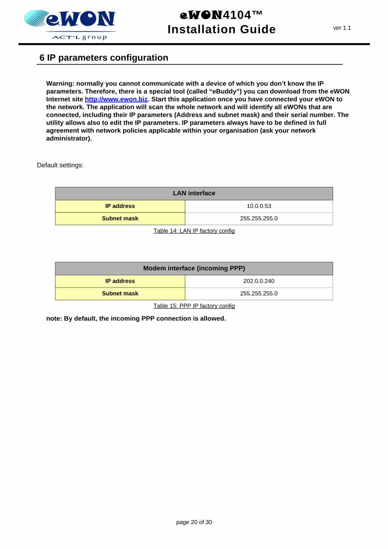
Warning: normally you cannot communicate with a device of which you don’t know the IP parameters. Therefore, there is a special tool (called “eBuddy”) you can download from the eWON Internet site http://www.ewon.biz. Start this application once you have connected your eWON to the network. The application will scan the whole network and will identify all eWONs that are connected, including their IP parameters (Address and subnet mask) and their serial number. The utility allows also to edit the IP parameters. IP parameters always have to be defined in full agreement with network policies applicable within your organisation (ask your network administrator).
Default settings:
note: By default, the incoming PPP connection is allowed.
LAN interface
IP address 10.0.0.53
Subnet mask 255.255.255.0
Table 14: LAN IP factory config
Modem interface (incoming PPP)
IP address 202.0.0.240
Subnet mask 255.255.255.0
Table 15: PPP IP factory config
page 20 of 30
eWON4104™Installation Guide ver 1.1
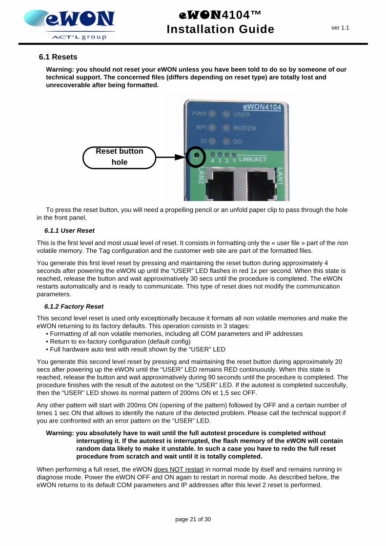
6.1 ResetsWarning: you should not reset your eWON unless you have been told to do so by someone of our technical support. The concerned files (differs depending on reset type) are totally lost and unrecoverable after being formatted.
To press the reset button, you will need a propelling pencil or an unfold paper clip to pass through the hole in the front panel.
6.1.1 User Reset
This is the first level and most usual level of reset. It consists in formatting only the « user file » part of the non volatile memory. The Tag configuration and the customer web site are part of the formatted files.
You generate this first level reset by pressing and maintaining the reset button during approximately 4 seconds after powering the eWON up until the “USER” LED flashes in red 1x per second. When this state is reached, release the button and wait approximatively 30 secs until the procedure is completed. The eWON restarts automatically and is ready to communicate. This type of reset does not modify the communication parameters.
6.1.2 Factory Reset
This second level reset is used only exceptionally because it formats all non volatile memories and make the eWON returning to its factory defaults. This operation consists in 3 stages:
• Formatting of all non volatile memories, including all COM parameters and IP addresses• Return to ex-factory configuration (default config)• Full hardware auto test with result shown by the “USER” LED
You generate this second level reset by pressing and maintaining the reset button during approximately 20 secs after powering up the eWON until the “USER” LED remains RED continuously. When this state is reached, release the button and wait approximatively during 90 seconds until the procedure is completed. The procedure finishes with the result of the autotest on the “USER” LED. If the autotest is completed succesfully, then the “USER” LED shows its normal pattern of 200ms ON et 1,5 sec OFF.
Any other pattern will start with 200ms ON (opening of the pattern) followed by OFF and a certain number of times 1 sec ON that allows to identify the nature of the detected problem. Please call the technical support if you are confronted with an error pattern on the “USER” LED.
Warning: you absolutely have to wait until the full autotest procedure is completed without interrupting it. If the autotest is interrupted, the flash memory of the eWON will contain random data likely to make it unstable. In such a case you have to redo the full reset procedure from scratch and wait until it is totally completed.
When performing a full reset, the eWON does NOT restart in normal mode by itself and remains running in diagnose mode. Power the eWON OFF and ON again to restart in normal mode. As described before, the eWON returns to its default COM parameters and IP addresses after this level 2 reset is performed.
Reset button hole
page 21 of 30
eWON4104™Installation Guide ver 1.1
7 Technical support
If you need technical support, simply fill out the form on the Web site http://support.ewon.biz/php/contact.php or send an email with the problem description to [email protected].
You will also find usefull documentation at http://support.ewon.biz
8 Appendix: Pinouts and connections
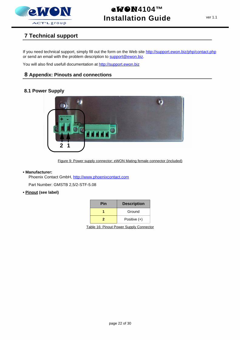
8.1 Power Supply
Figure 9: Power supply connector: eWON Mating female connector (included)
• Manufacturer:Phoenix Contact GmbH, http://www.phoenixcontact.com
Part Number: GMSTB 2,5/2-STF-5.08
• Pinout (see label)
Pin Description
1 Ground
2 Positive (+)
Table 16: Pinout Power Supply Connector
2 1
+ -
page 22 of 30
eWON4104™Installation Guide ver 1.1
8.2 Ethernet
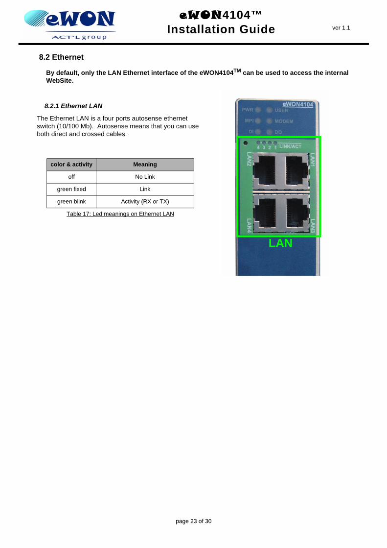
By default, only the LAN Ethernet interface of the eWON4104TM can be used to access the internal WebSite.
8.2.1 Ethernet LAN
The Ethernet LAN is a four ports autosense ethernet switch (10/100 Mb). Autosense means that you can use both direct and crossed cables.
color & activity Meaning
off No Link
green fixed Link
green blink Activity (RX or TX)
Table 17: Led meanings on Ethernet LAN
LAN
page 23 of 30
eWON4104™Installation Guide ver 1.1
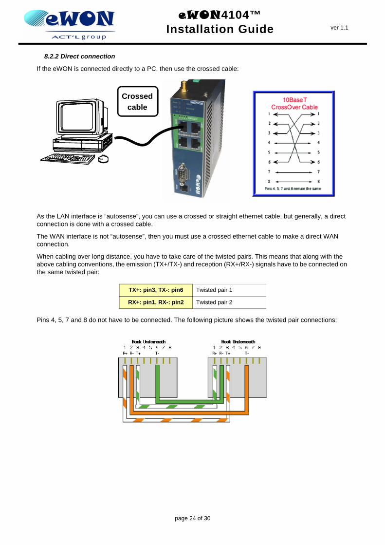
8.2.2 Direct connection
If the eWON is connected directly to a PC, then use the crossed cable:
As the LAN interface is “autosense”, you can use a crossed or straight ethernet cable, but generally, a direct connection is done with a crossed cable.
The WAN interface is not “autosense”, then you must use a crossed ethernet cable to make a direct WAN connection.
When cabling over long distance, you have to take care of the twisted pairs. This means that along with the above cabling conventions, the emission (TX+/TX-) and reception (RX+/RX-) signals have to be connected on the same twisted pair:
Pins 4, 5, 7 and 8 do not have to be connected. The following picture shows the twisted pair connections:
TX+: pin3, TX-: pin6 Twisted pair 1
RX+: pin1, RX-: pin2 Twisted pair 2
Crossed cable
page 24 of 30
eWON4104™Installation Guide ver 1.1
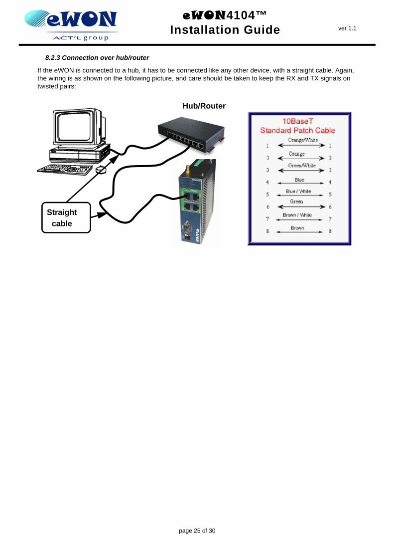
8.2.3 Connection over hub/router
If the eWON is connected to a hub, it has to be connected like any other device, with a straight cable. Again, the wiring is as shown on the following picture, and care should be taken to keep the RX and TX signals on twisted pairs:
Hub/Router
Straight cable
page 25 of 30
eWON4104™Installation Guide ver 1.1
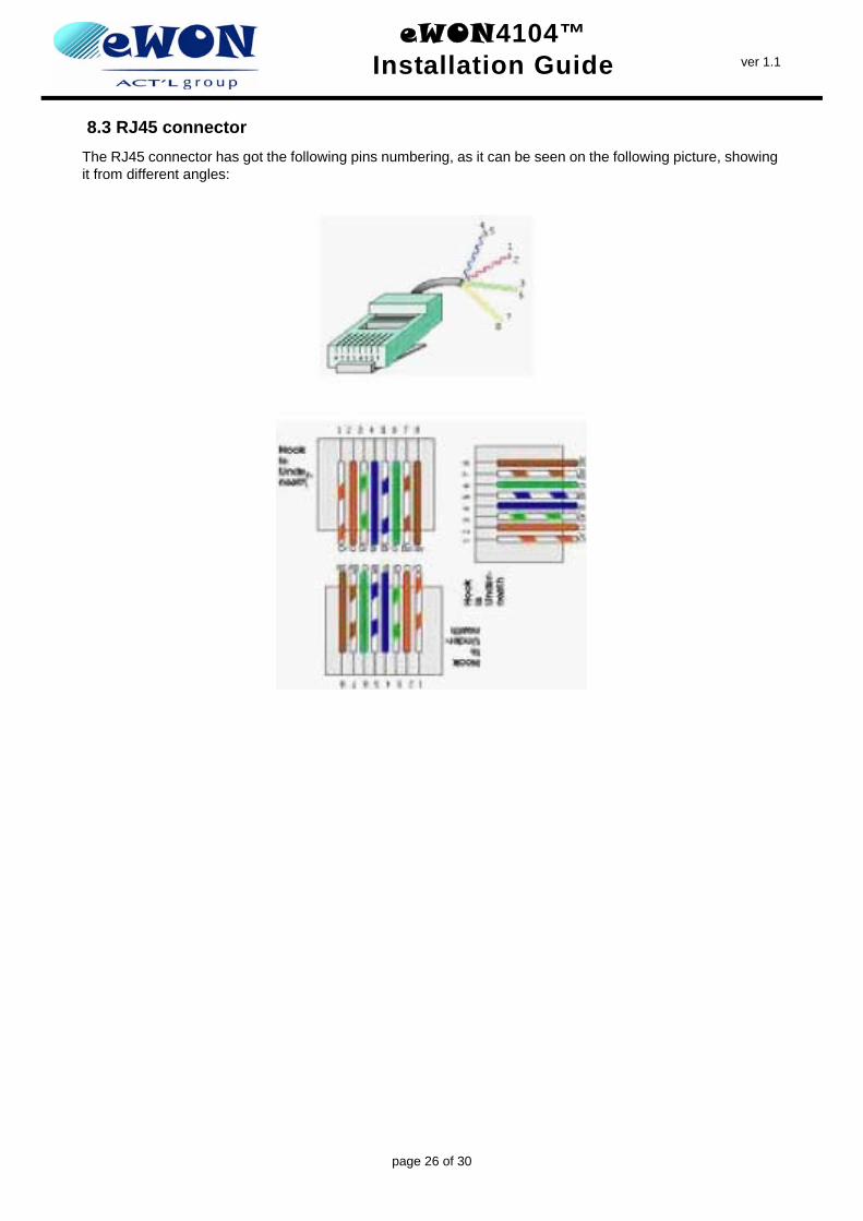
8.3 RJ45 connectorThe RJ45 connector has got the following pins numbering, as it can be seen on the following picture, showing it from different angles:
page 26 of 30
eWON4104™Installation Guide ver 1.1
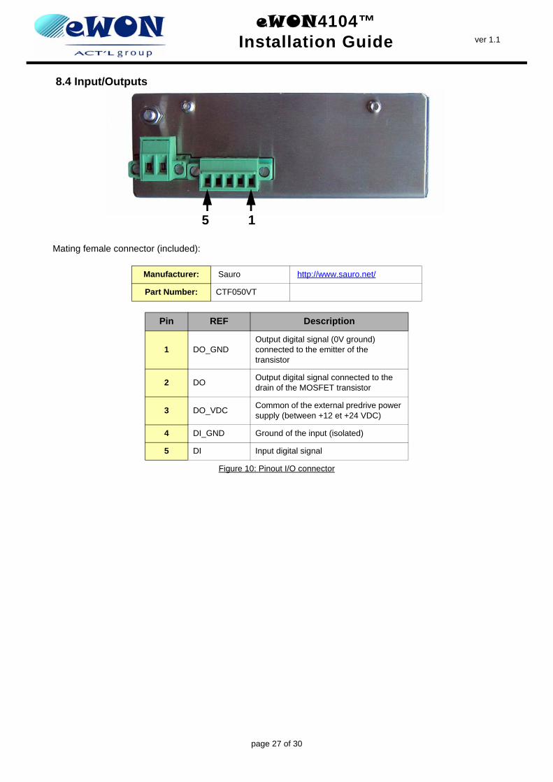
8.4 Input/Outputs
Mating female connector (included):
Manufacturer: Sauro http://www.sauro.net/
Part Number: CTF050VT
Pin REF Description
1 DO_GNDOutput digital signal (0V ground) connected to the emitter of the transistor
2 DO Output digital signal connected to the drain of the MOSFET transistor
3 DO_VDC Common of the external predrive power supply (between +12 et +24 VDC)
4 DI_GND Ground of the input (isolated)
5 DI Input digital signal
Figure 10: Pinout I/O connector
5 1
page 27 of 30
eWON4104™Installation Guide ver 1.1
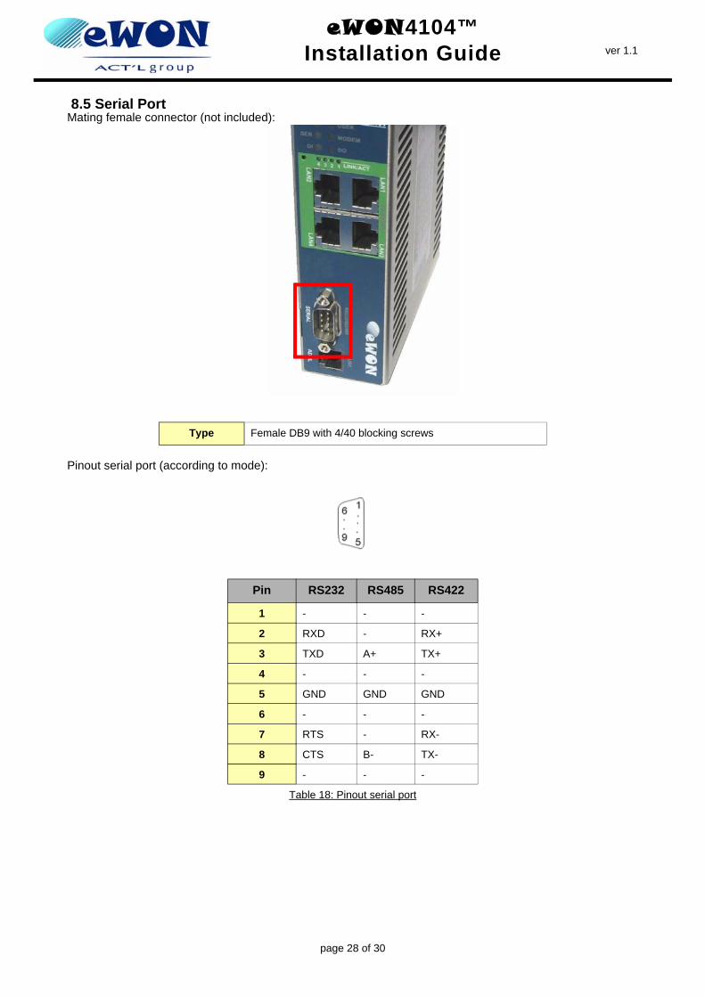
8.5 Serial PortMating female connector (not included):
Pinout serial port (according to mode):
Type Female DB9 with 4/40 blocking screws
Pin RS232 RS485 RS422
1 - - -
2 RXD - RX+
3 TXD A+ TX+
4 - - -
5 GND GND GND
6 - - -
7 RTS - RX-
8 CTS B- TX-
9 - - -
Table 18: Pinout serial port
page 28 of 30
eWON4104™Installation Guide ver 1.1
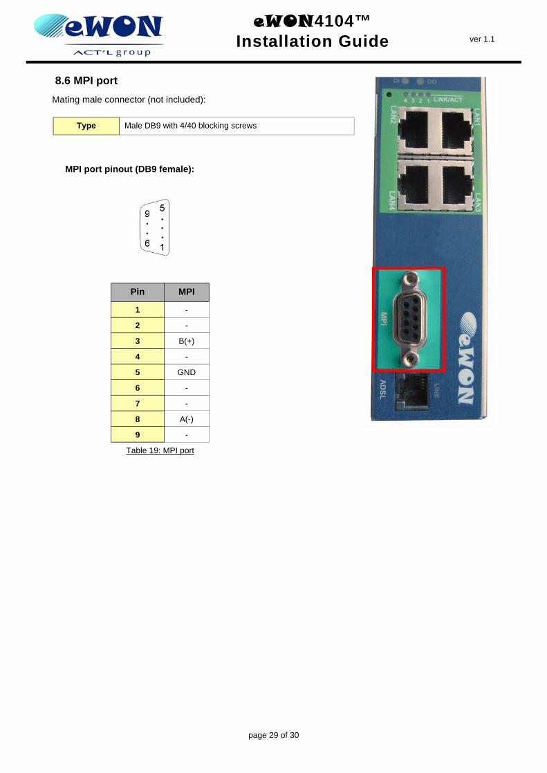
8.6 MPI portMating male connector (not included):
MPI port pinout (DB9 female):
Type Male DB9 with 4/40 blocking screws
Pin MPI
1 -
2 -
3 B(+)
4 -
5 GND
6 -
7 -
8 A(-)
9 -
Table 19: MPI port
page 29 of 30
eWON4104™Installation Guide ver 1.1
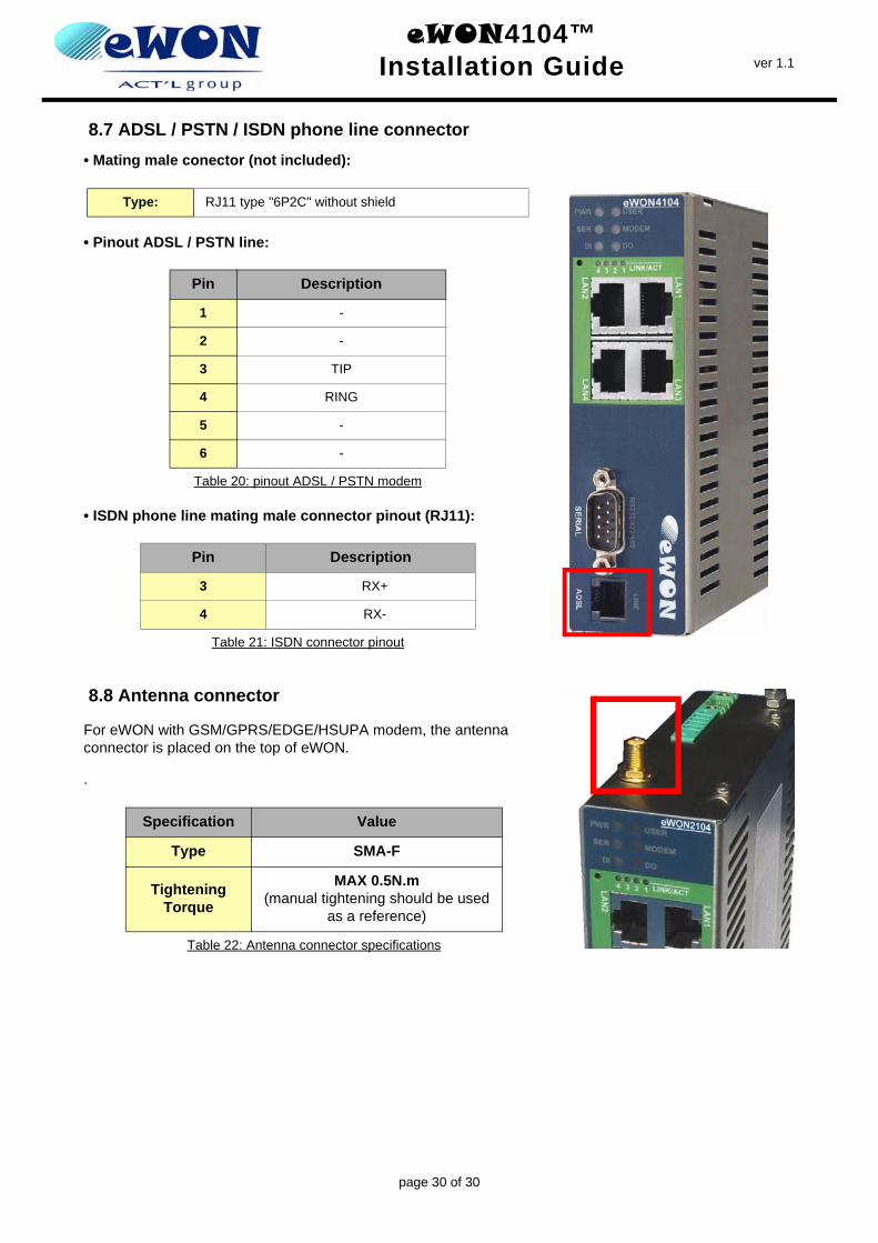
8.7 ADSL / PSTN / ISDN phone line connector• Mating male conector (not included):
• Pinout ADSL / PSTN line:
• ISDN phone line mating male connector pinout (RJ11):
8.8 Antenna connector
For eWON with GSM/GPRS/EDGE/HSUPA modem, the antenna connector is placed on the top of eWON.
.
Type: RJ11 type "6P2C" without shield
Pin Description
1 -
2 -
3 TIP
4 RING
5 -
6 -
Table 20: pinout ADSL / PSTN modem
Pin Description
3 RX+
4 RX-
Table 21: ISDN connector pinout
Specification Value
Type SMA-F
Tightening Torque
MAX 0.5N.m(manual tightening should be used
as a reference)
Table 22: Antenna connector specifications
page 30 of 30