adq-90+ power splitter/combiner adq-90 - mini circuits ... · adq-90 total loss 2.4 2.8 3.2 3.6 4.0...

1
Notes A. Performance and quality attributes and conditions not expressly stated in this specification document are intended to be excluded and do not form a part of this specification document. B. Electrical specifications and performance data contained in this specification document are based on Mini-Circuit’s applicable established test performance criteria and measurement instructions. C. The parts covered by this specification document are subject to Mini-Circuits standard limited warranty and terms and conditions (collectively, “Standard Terms”); Purchasers of this part are entitled to the rights and benefits contained therein. For a full statement of the Standard Terms and the exclusive rights and remedies thereunder, please visit Mini-Circuits’ website at www.minicircuits.com/MCLStore/terms.jsp Mini-Circuits ® www.minicircuits.com P.O. Box 350166, Brooklyn, NY 11235-0003 (718) 934-4500 [email protected] Page 1 of 1 A B C D E F G .397 .032 .385 .435 .310 .215 .100 10.08 0.81 9.78 11.05 7.87 5.46 2.54 H J K L M N P wt .015 .025 .035 .075 .120 .060 .420 grams 0.38 0.64 0.89 1.91 3.05 1.52 10.67 0.45 Frequency (MHz) Total Loss 1 (dB) Amplitude Unbalance (dB) Isolation (dB) Phase Unbalance (deg.) VSWR S VSWR 1 VSWR 2 S-1 S-2 ADQ-90 TOTAL LOSS 2.4 2.8 3.2 3.6 4.0 4.4 54 60 66 72 78 84 90 FREQUENCY (MHz) TOTAL LOSS (dB) S-1(dB) S-2(dB) Typical Performance Data Electrical Specifications Maximum Ratings Pin Connections SUM PORT 1 PORT 1 (+90°) 8 PORT 2 (0°) 4 GROUND 2,3,6,7 50 OHM TERM EXTERNAL 5 Operating Temperature -40°C to 85°C Storage Temperature -55°C to 100°C Power Input (as a splitter) 0.5W max. ADQ-90+ ADQ-90 2 Way-90° 5055 to 90 MHz Power Splitter/Combiner REV. D M151107 ADQ-90 HY/TD/CP 150522 Surface Mount Features • good isolation, 26 dB typ. • good input port matching VSWR, 1.12 typ. • good output port matching VSWR, 1.10 typ. • excellent phase unbalance, 1 deg. typ. • small surface mount package • protected under U.S. Patent 6,133,525 Applications • VHF • image rejection • IF signal processing CASE STYLE: CJ725 ADQ-90 ISOLATION 23 24 25 26 27 28 54 60 66 72 78 84 90 FREQUENCY (MHz) ISOLATION (dB) ADQ-90 PHASE UNBALANCE 89.2 89.6 90.0 90.4 90.8 91.2 54 60 66 72 78 84 90 FREQUENCY (MHz) PHASE UNBALANCE (Deg.) electrical schematic FREQ. RANGE (MHz) ISOLATION (dB) INSERTION LOSS (dB) Avg. of Coupled Outputs ABOVE 3 dB PHASE UNBALANCE (Degrees) AMPLITUDE UNBALANCE (dB) f L -f U Typ. Min. Typ. Max. Max. Max. 55-90 26 20 0.2 0.7 4 1.2 Outline Dimensions ( ) inch mm Demo Board MCL P/N: TB-83 Suggested PCB Layout (PL-063) 54.00 3.47 2.95 0.53 24.54 89.58 1.11 1.13 1.11 56.00 3.37 3.05 0.33 24.59 89.62 1.11 1.13 1.11 58.00 3.29 3.13 0.16 24.67 89.67 1.11 1.13 1.11 60.00 3.21 3.21 0.00 24.75 89.67 1.11 1.13 1.11 62.00 3.14 3.29 0.14 24.83 89.73 1.11 1.13 1.11 64.00 3.09 3.35 0.26 24.92 89.76 1.10 1.13 1.10 66.00 3.04 3.40 0.37 25.02 89.77 1.10 1.13 1.10 68.00 3.00 3.45 0.46 25.12 89.87 1.10 1.13 1.10 70.00 2.96 3.50 0.54 25.25 89.88 1.09 1.13 1.10 73.00 2.93 3.55 0.62 25.42 90.02 1.09 1.14 1.10 76.00 2.91 3.58 0.67 25.64 90.08 1.08 1.14 1.10 79.00 2.92 3.60 0.67 25.83 90.20 1.08 1.14 1.10 82.00 2.95 3.59 0.64 26.06 90.33 1.08 1.14 1.10 85.00 2.99 3.57 0.58 26.32 90.49 1.07 1.15 1.11 90.00 3.11 3.48 0.37 26.77 90.75 1.06 1.16 1.11 Outline Drawing PCB Land Pattern Suggested Layout, Permanent damage may occur if any of these limits are exceeded. 1. Total Loss = Insertion Loss + 3dB splitter loss. +RoHS Compliant The +Suffix identifies RoHS Compliance. See our web site for RoHS Compliance methodologies and qualifications

Upload: vuongque

Post on 24-Jan-2019

217 views

Category:

Documents


0 download

TRANSCRIPT

NotesA. Performance and quality attributes and conditions not expressly stated in this specification document are intended to be excluded and do not form a part of this specification document. B. Electrical specifications and performance data contained in this specification document are based on Mini-Circuit’s applicable established test performance criteria and measurement instructions. C. The parts covered by this specification document are subject to Mini-Circuits standard limited warranty and terms and conditions (collectively, “Standard Terms”); Purchasers of this part are entitled to the rights and benefits contained therein. For a full statement of the Standard Terms and the exclusive rights and remedies thereunder, please visit Mini-Circuits’ website at www.minicircuits.com/MCLStore/terms.jsp

Mini-Circuits®

www.minicircuits.com P.O. Box 350166, Brooklyn, NY 11235-0003 (718) 934-4500 [email protected] Page 1 of 1

A B C D E F G.397 .032 .385 .435 .310 .215 .100

10.08 0.81 9.78 11.05 7.87 5.46 2.54

H J K L M N P wt.015 .025 .035 .075 .120 .060 .420 grams0.38 0.64 0.89 1.91 3.05 1.52 10.67 0.45
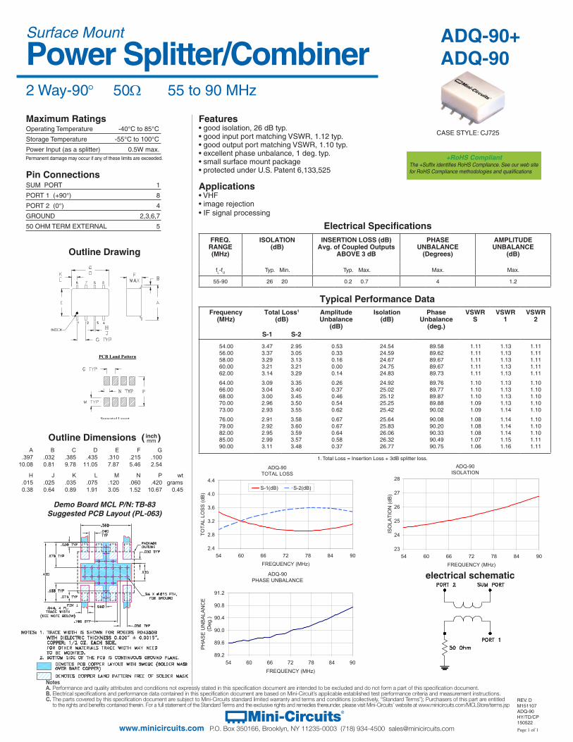
Frequency(MHz)

Total Loss1

(dB)AmplitudeUnbalance

(dB)

Isolation(dB)

PhaseUnbalance

(deg.)

VSWRS

VSWR1

VSWR2

S-1 S-2

ADQ-90TOTAL LOSS

2.4

2.8

3.2

3.6

4.0

4.4

54 60 66 72 78 84 90FREQUENCY (MHz)

TOTA

L LO

SS

(dB

)

S-1(dB) S-2(dB)

Typical Performance Data

Electrical Specifications

Maximum Ratings

Pin ConnectionsSUM PORT 1

PORT 1 (+90°) 8

PORT 2 (0°) 4

GROUND 2,3,6,7

50 OHM TERM EXTERNAL 5

Operating Temperature -40°C to 85°C

Storage Temperature -55°C to 100°C

Power Input (as a splitter) 0.5W max.

ADQ-90+ADQ-90

2 Way-90° 50Ω 55 to 90 MHz

Power Splitter/Combiner

REV. DM151107ADQ-90HY/TD/CP150522

Surface Mount

Features• good isolation, 26 dB typ.• good input port matching VSWR, 1.12 typ.• good output port matching VSWR, 1.10 typ.• excellent phase unbalance, 1 deg. typ.• small surface mount package• protected under U.S. Patent 6,133,525

Applications• VHF• image rejection• IF signal processing

CASE STYLE: CJ725

ADQ-90ISOLATION

23

24

25

26

27

28

54 60 66 72 78 84 90FREQUENCY (MHz)

ISO

LATI

ON

(dB

)

ADQ-90PHASE UNBALANCE

89.2

89.6

90.0

90.4

90.8

91.2

54 60 66 72 78 84 90FREQUENCY (MHz)

PH

AS

E U

NB

ALA

NC

E

(Deg

.)

electrical schematic

FREQ. RANGE(MHz)

ISOLATION(dB)

INSERTION LOSS (dB)Avg. of Coupled Outputs

ABOVE 3 dB

PHASE UNBALANCE

(Degrees)

AMPLITUDEUNBALANCE

(dB)

fL-fU Typ. Min. Typ. Max. Max. Max.

55-90 26 20 0.2 0.7 4 1.2

Outline Dimensions ( )inchmm

Demo Board MCL P/N: TB-83Suggested PCB Layout (PL-063)

54.00 3.47 2.95 0.53 24.54 89.58 1.11 1.13 1.11 56.00 3.37 3.05 0.33 24.59 89.62 1.11 1.13 1.11 58.00 3.29 3.13 0.16 24.67 89.67 1.11 1.13 1.11 60.00 3.21 3.21 0.00 24.75 89.67 1.11 1.13 1.11 62.00 3.14 3.29 0.14 24.83 89.73 1.11 1.13 1.11 64.00 3.09 3.35 0.26 24.92 89.76 1.10 1.13 1.10 66.00 3.04 3.40 0.37 25.02 89.77 1.10 1.13 1.10 68.00 3.00 3.45 0.46 25.12 89.87 1.10 1.13 1.10 70.00 2.96 3.50 0.54 25.25 89.88 1.09 1.13 1.10 73.00 2.93 3.55 0.62 25.42 90.02 1.09 1.14 1.10 76.00 2.91 3.58 0.67 25.64 90.08 1.08 1.14 1.10 79.00 2.92 3.60 0.67 25.83 90.20 1.08 1.14 1.10 82.00 2.95 3.59 0.64 26.06 90.33 1.08 1.14 1.10 85.00 2.99 3.57 0.58 26.32 90.49 1.07 1.15 1.11 90.00 3.11 3.48 0.37 26.77 90.75 1.06 1.16 1.11

Outline Drawing

PCB Land Pattern

Suggested Layout, Tolerance to be within ±.002

Permanent damage may occur if any of these limits are exceeded.

1. Total Loss = Insertion Loss + 3dB splitter loss.

+RoHS CompliantThe +Suffix identifies RoHS Compliance. See our web site for RoHS Compliance methodologies and qualifications