adjustable dc power supply - ietlabs.com adjustable dc power supply.pdf · type 1265-a adjustable...
TRANSCRIPT

OPERATING INSTRUCTIONS
TYPE 1265-A
ADJUSTABLE DC POWER SUPPLY
GENE RAl RADIO COMPANY
A
.......
"' o-01 I
)>

O·PERATING INSTRUCTIONS
TYPE 1265-A
ADJUSTABLE DC POWER SUPPLY
Form 1265-0100-A October, 1962
Copyright 1962 by General Radio Company West Concord, Massachusetts, USA
GENERAL R A D I 0 COMPANY WEST CONCORD, MASSACHUSETTS, USA

TABLE OF
Section 1. INTRODUCTION .
1.1 Purpose . . . • • • 1.2 Description. . . . .
CONTENTS
Section 2. OPERATING PROCEDURE
1
1 1
3
2.1 Input Power Connections • . . • 3 2.2 Load Connections • • • • • . . • • • • 3 2.3 Selection of Constant Current or Constant Voltage Mode • 3 2.4 Load Voltage and Current Adjustments • • • • 3 2.5 Use at High Temperatures . . • • • • • • • 4 2.6 Operation With AC Applied to Output. • 4 2.7 Impedance Ranges • • • . . • • 4
Section 3. PRINCIPLES OF OPERATION. •
3.1 3.2 3.3 3.4 3.5 3.6
General • . . . . . • .• Phase -Controlled Rectifiers • • • • Output Circuit. • . • • • • Sampling and Metering Circuits . • Differential Amplifier and Reference Circuits Overload Trigger Circuit. • . . .
Section 4. SERVICE AND MAINTENANCE •
4.1 Warranty. • . • . . 4.2 Service. • . . • . . 4.3 Internal Adjustments. • 4.4 Trouble Shooting
Section 5. PARTS LIST.
5
5 5 6 6 7 7
7
7 7 8 8
10

Figure 1-1.
Panel View of Type 1265-A Adjustable DC Power Supply.
SPECIFICATIONS
Full-Scale Output Ranges: 12.5, 40, 125, 400 volts, de;
0.16, 0.5, 1.6, 5 amperes, de; in any combination up to 200 watts. Meters: Voltage and current; ranges are switched with
output ranges . Accuracy- ±3%. Overload Protection: Overload circuit trips at approxi
mately n~ times full-scale current. Regulation: (Voltage or current) 0.2% for 10% line-volt
age change; 1% for a change from full load to half load. Speed of Response: Approximately 0.1 second. Hum Level (rms): Approximately 70 db below full scale de output (60 db on 12.5-volt, 5-ampere range).
Accessories Supplied:· Type CAP-22 3-Wire Power Cord
and spare fuses. Mounting: Relay-rack panel with cabinet; Type 1265-AR includes fittings to permit either the instrument or the cabinet to be removed from the rack without disturbing the other; Type 1265-AM has end supports for table or
bench use. Dimensions: Bench model, width 19, height 7~, depth 17X inches (485 by 190 by 440 mm), over-all; rack model,
panel 19 by 7 inches (485 by 180 mm), depth behind
panel, 15 inches (385 mm). Net Weight: 80 pounds (37 kg).
This instrument is licensed under patents of the American Telephone and Telegraph Company solely for utilization in
research, investigation, measurement testing, instruction and development work in pure and applied science.

INTRODUCTION
SECTION 1
INTRODUCTION
WARNING
This instrument is capable of delivering lethal energy. All loads and
connections should be well insulated to avoid accidental contact. Always turn
the OUTPUT to zero before disconnecting the load or changing the range. The OUTPUT SHORTED position of the OUTPUT control ensures that
the output voltage is zero. However, do not set this control to the OUTPUT
SHORTED position unless the voltmeter indicates a low output voltage. This
will prevent damage to the shorting switch.
Use particular care when operating the instrument in the CONSTANT
CURRENT mode. In this case, an open-circuited output will result in a maxi·
mum value of output voltage. The open-circuit discharge time constant is ap
proximately 16 seconds; therefore the output capacitors are not discharged immediately when the instrument is turned OFF or when the OUTPUT control
is set to zero.
1.1 PURPOSE.
The Type 1265-A Adjustable DC Power Supply (Figure 1-1) is a multi -range unit that provides high power to a wide range of load resistances. It was designed primarily as a current bias supply for the Type 1630- A Inductance Measuring Assembly, for use at various impedance levels, over a wide control range. It is particularly useful where large variations in load resistance and power are needed.
1.2 DESCRIPTION.
1.2.1 GENERAL. The instrument supplies constant voltage (up to 400 de volts) in four ranges and constant current (up to 5 de amperes) at a maximum power of 200 watts. The output is adjustable and is monitored by front-panel voltage and current meters. The output circuit is passive; this permits a large alternating current to flow across the output, without overloading the regulating circuit. This feature is particularly useful when ac and de voltages must be combined to give a composite waveform.
The control amplifier regulates the output level through control of the "firing angles" of the phasecontroll.ed rectifiers (see Figure 1-2). A frontpanel switch selects either voltage- or current-regulated output. Regulation is obtained by comparison
of the output voltage or current with an adjustable reference signal. Any difference between the two signals changes the "firing angles" of the rectifiers to keep the output at the desired level.
The output is available at the red (high) and the gray(low)binding posts on therearpanel. The third (metallic) binding post connects directly to the chassis. This can be used as a grounding point for the chassis or for either side of the load.
A circuit breaker, reset by a switch on the front panel, provides overload protection to avoid damage to the instrument caused by short circuits that occur during constant-voltage operation.
1.2.2 MOUNTING. The instrument is available as either the Type 1265-AM, equipped with aluminum end frames (Type ZFRI-414-3) for bench mounting, or Type 1265-AR, for relay-rack mounting, with mounting brackets (Type ZSU-6-4) included. These brackets permit either the cabinet or the instrument to be withdrawn independently of the other. Instructions for installing the Type 1265- AR in a relay rack accompany these brackets.
1.2.3 ACCESSORIES SUPPLIED. One Type CAP-22 three-wire Power Cord and spare fuses are supplied with the instrument.
.. TYPE 1265-A ADJUSTABLE DC POWER SUPPLY
T/01
PUT
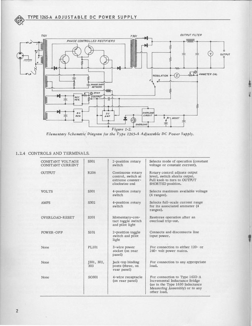
Figure 1-2. Elementary Schematic Diagram for the Type 1265-A Adjustable DC Power Supply.
1.2.4 CONTROLS AND TERMINALS.
CONSTANT VOLTAGE S301 2-position rotary Selects mode of operation (constant CONSTANT CURRENT switch voltage or constant current).
OUTPUT R206 Continuous rotary Rotary control adjusts output control, switch at level, switch shorts output. extreme counter- Pull knob to turn to OUTPUT clockwise end SHORTED position.
VOLTS S301 4-position rotary Selects maximum available voltage switch (4 ranges).
AMPS S302 4-position rotary Selects full- scale current range switch for its associated ammeter (4
ranges).
OVERLOAD-RESET S201 Momentary-con- Restores operation after an tact toggle switch overload trip-out. and pilot light
POWER-OFF S101 2-position toggle Connects and disconnects line switch and pilot input power. light
None PL101 3-wire power For connection to either 120- or socket (on rear 240- volt power mains. panel)
None J301, 302, Jack-top binding For connection to any appropriate 303 posts (three, on load.
rear panel)
None S0301 4-wire receptacle For connection to Type 1633-A (on rear panel) Incremental Inductance Bridge
(as in the Type 1630 Inductance Measuring Assembly) or to any other load.
2

SECTION 2 OPERATING
2.1 INPUT POWER CONNECTIONS.
2.1.1 120-VOLT OPERATION. Terminals 1 and 2 should be connected to terminals 3 and 4, respectively, on power transformer T101 (see the schematic diagram, Figure 4-2). The rating of each of the pair of fuses on the rear panel should be 5 amperes, and the voltage label (above the power input socket) should read "105-125 v, 50-60 c." (Refer to paragraph 2.1.3.)
2.1.2 240-VOLT OPERATION. Remove the connections between terminals 1 and 3 and terminals 2 and 4 on power transformer T101; connect terminals 2 and 3. The rating of each of the pair of fuses on the rear panel should be 2.5 amperes, and the voltage label (above the power input socket) should read "210-250 v, 50-60 c." (Refer to paragraph 2.1.3.)
2.1.3 GENERAL.
NOTE
Always be sure the POWER switch is
turned OFF before the instrument is connected to the power mains.
Connect the instrument to a power source that corresponds with the reading of the nameplate above the power input socket (105-125 v or 210-250 v, 50-60 c). If a three-wire (grounded) power receptacle is not available for use with the three-wire power cord (supplied), a two-wire adaptor, Type CDPP-11 can be used. The case of the instrument should then be connected to a suitable ground.
2.2 LOAD CONNECTIONS.
WARNING
Always turn the OUTPUT control to zero before connecting or disconnecting the load; when the output
voltmeter reads zero volts, turn the 0 UT PUT control to the OUTPUT SHORTED position.
Do not use the OUTPUT SHORTED position as a means of discharging the internal capacitors quickly, because the current rating of the switch may be greatly exceeded by the extremely large peak currents that are possible.
OPERATING PROCEDURE
PROCEDUR,E
The load can be connected to either the pair of binding posts or to the multipoint connector, on the rear panel. Figure 2-1 shows the output connections. Either the positive (red) or the negative (gray) bindingpost can be grounded to the case of the instrument. The connecting link attached to the metal post can be used to ground the neganve terminal; an additional lead is required to ground the positive terminal.
2.3 SELECTION OF CONSTANT CURRENT OR CONSTANT VOLT AGE MODE.
The CONSTANT CURRENT mode of operation should be used when the Type 1265- A Power Supply is used with the Type 1633- A Incremental Inductance Bridge (as in the Type 1630 Inductance Measuring Assemblies). This mode of operation keeps the de magnetic field intensity constant as the resistance of the unknown inductor changes, due to internal heating.
TI1e CONSTANT VOLTAGE mode is usually preferable for general applications of the power supply.
2.4 LOAD VOLTAGE AND CURRENT ADJUSTMENTS.
With the OUTPUT control set at the OUTPUT SHORTED position, select the desired ranges on the VOLTS and AMPS switches. These switches are mechanically interlocked to prevent the product of the two range settings from exceeding 200 watts.
Turn the POWER switch on, with the OUTPUT control still at the OUTPUT SHORTED position. The pilot lamp should light. If the OVERLOAD lamp also lights, operate its associated toggle switch to extinguish it and to restore the circuit.
Figure 2·1. The load can be con·
nected to either the binding posts
or the multipoint connector, on the
rear panel of the Type 1265-A Adjustable DC PowerS upply, as
shown.
3

.. TYPE 1265-A ADJUSTABLE DC POWER SUPPLY
Slowly increase the setting of the OUTPUT control until the panel meters indicate the desired output. The ranges of the meters and the output level are determined by the settings of the range switches. In the CONSTANT VOLTAGE mode of operation, a current approximately 1-1/2 times the full-scale value will trip the OVERLOAD relay, and will reduce the output to zero. The required output must be reduced or the switch settings changed to higher values and the OVERLOAD switch must be reset before output can be restored. The OUTPUT control must be returned to the OUTPUT SHORTED position whenever the range settings are changed, to avoid harmful transient effects. The best control resolution and the most accurate meter readings are obtained with the range switches set to the lowest values that will give the required output.
2.5 USE AT HIGH TEMPERATURES.
A thermally activated circuit breaker is included in the Type 1265-A. The power supply can deliver no power when this breaker is activated. This occurs only at very high temperatures, in which case the instrument should be turned off and allowed to cool until automatic resetting of the breaker takes place and the output is again available.
2.6 OPERATION WITH AC APPLIED TO OUTPUT.
For some applications, particularly the testing of iron core devices, a comP.Osite signal, containing both ac and de, is required.! The low, passive, ac impedance of the power supply permits the passage
1000
500
200
~ 100 / _J
0 >
4
50
20
10 0.1
"" o9'
' fbo
"~ / I'"' " / />" ", / ' ~ " 0~
// "~ /<o
/ " X/ "' " / "' "' ~ / / "'- ~vq,y-
// "' / "'~ / y oo
/ /~ ~ '1';.,-v" // o.S'
/ f'-19.
/ / ~~--0.5 1.6 5 )'o.S' 10 0.2
AMPERES
of a large ac current whose value depends upon the settings of the VOLTS and AMPS switches, as given in Table 1. These values are for continuous operation, in an ambient temperature of 70 F. For lowduty-cycle, intermittent operation, these ratings may be increased 25%; for operation at higher temperatures, they should be reduced one percent per degree F.
Operation with an ac voltage across the OUTPUT terminals of the power supply that is larger than the de output voltage should be avoided. Because of the low output impedance, this should offer no problem except when the de is reduced to zero, in which case the OUTPUT control should be set to the OUTPUT SHORTED position.
2.7 IMPEDANCE RANGES.
This multi-range supply is designed to deliver maximum power (200 watts) to any of three impedances, 8, 80, or 800 ohms, as shown in Figure 2-2. The figure also indicates the maximum value of power that can be delivered to a load of any resistance. Note that, in the CONSTANTCURRENTmode of operation, the instrument regulates properly, even when the output voltage is above the nominal limit, as long as the output current is less than the maximum allowable value. For this reason, the scale of the voltmeter extends somewhat beyond the nominal range limit indicated on the VOLTS switch.
lThe General Radio Type 1266-A Adjustable AC Power Source (at line fre
quency) and the Type 1308-A Audio Oscillator and Power Amplifier (20 cps
to 20 kc) are recommended.
Figure 2-2. Maximum load capabilities of the Type 1265-A
Adjustable nc Power Supply.
-----------~----- -
OPERATING PROCEDURE- PRINCIPLESOF OPERATION
Table 1
Capacitance and Ripple Current VS Range Switch Setting
VOLTS SWITCH SETTING
12.5 40 125 400
8100 fJf 8100 IJf Output Capacitor
11) 5.6 amp 5.6 amp 60-Cycle Ripple Current
7.0 7.0 120-Cycle Current
9.8 9.8 400 Cps and Higher
8100 IJf 3100 fJf 1100 IJf Output Capacitor
": 5.6 amp 3.6 amp 2.2 amp 60- Cycle Ripple Current
...... 7.0 4.5 3.2 120-Cycle Current
9.8 6.3 4.5 400 Cps and Higher
3100 IJf 1100 IJf 320 IJf 80 IJf Output Capacitor
11) 3.6 amp 2.2 amp 2.2 amp l.1amp 60-Cycle Ripple Current
0 4.5 3.2 3.1 1.5 120-Cycle Current
6.3 4.5 4.4 2.2 400 Cps and Higher
1100 f.lf 320 IJf 80 IJf 50 IJf Output Capacitor
'-0 2.2 amp 2.2 amp 1.1 amp 0.75 amp 60- Cycle Ripple Current ...... 0 3.2 3.1 1.5 1.1 120-Cycle Current
4.5 4.4 2.2 1.5 400 Cps and Higher
SECTION 3 PRINCIPLES OF OPERATION
3.1 GENERAL.
The output of the instrument is regulated by control of the current in the circuit loop that includes the secondary of the input transformer and the primary of the output transformer. This type of circuit permits the control of a wide range of output voltages by a single control circuit, since a variety of voltages can be obtained by the use of several different taps on the secondary of the output transformer. The elementary circuit diagram, Figure 1-2, shows how the voltage or current is sampled, amplified, and applied to the controlled rectifiers.
3.2 PHASE-CONTROLLED RECTIFIERS.
The controlled rectifiers are two, transistor, trigger circuits (see Figure 1-2). The second (PNP)
transistor in the diagram actually consists of four transistors that provide the power gain and the rating needed to control the high peak currents (see the complete schematic diagram, Figure 4- 2). The feedback resistor, Rll8, provides regeneration to ensure that these trigger circuits are either full off or full on.
These controlled rectifier circuits are triggered when the base voltages of the input (NPN) transistors are slightly positive with respect to the common emitter terminals. The de controlling voltage from the amplifier is added to a line-frequency signal that lags the voltage across the rectifier by 90 degrees. As the controlling voltage varies, it changes the time at which this composite signal is sufficient to trigger the rectifiers. Thus the time duration of the output current pulse is adjusted. Figure 3-1 illustrates this operation.
5

~--T_Y_PE __ 12_65_-A __ A_D_J_U_S_T_A_B_L_E_D_C __ P_O_W_E_R __ SU_P_P_L_Y __________________________ __
OUTPUT VOLT AGE OF
TRANSFORMER TIOI........_
CONTROL DC t
-t-.--CIRCUIT
TRIGGERS
Figure 3·1. Method of _varying • firing angle"
of controlled rectifiers.
Actual current and voltage waveforms are shown in Figure 3-1. It should be noted that, due to the capacitor input of the output filter, the current pulse does not necessarily last to the end of the positive half-cycle of the voltage, particularly when the instrument is under light load.
3.3 OUTPUT CIRCUIT.
The output circuit consists of a full-wave rectifier that feeds a capacitive-input LC filter. The setting of the VOLTS switch determines the particular transformer voltage and the rectifiers that are used. The values of capacitance and inductance are selected by the settings of the VOLTS and the AMPS
switches, as given in Table 2. The capacitors have values proportional to the optimum load for each range; thus the circuit time constants are independent of the range settings. The capacitors are shunted by internal resistors so that they are discharged when the output is an open circuit. This discharge time constant is approximately 16 seconds.
3.4 SAMPLING AND METERING CIRCUITS.
The instrument can be either current or voltage regulated, depending upon which output quantity is sampled. The current is sampled across a resistor in series with the output, and thevoltage is sampled by a voltage divider network across the output. These quantities are measured before the output filter so that the phase shift due to the filter and the load does not affect the control loop. The sampled de current and voltage are equal to the corresponding output quantities except for the direct current IR drop in the filter and the current in the resistors that shunt the capacitors. To compensate for these small differences, the appropriate voltages are added in the control loop.
The voltmeter is placed directly across the output, with an appropriate series resistor to select the range. The ammeter is placed across the current- sampling resistor, whose value is changed with the current range.
Table 2
Components in Output Filter with Various Range Switch Settings
6
12.5
! C313, C322
ll"l 8100 fJf
L Tap #6 20 mh
C313, C322 \0 8100 fJf ..... L Tap #8
60 mh r-
C312, C321 3100 fJf
ll"l
0 L Tap #2 200 mh
C311, C320
\0 1100 fJf ...... 0
L Tap #1 600 mh
* In series. **In parallel.
VOLTS SWITCH SETTING 40 125 400
C313, C322 8100 f.l£
L Tap #6 20 mh
C312, C321 C311, C320 3100 f.!£ 1100 fJf
L Tap #2 L Tap #2 200 mh 200 mh
C311, C320 C309, C310** C307, C308* 1100 f.!£ C318, C319** C316, C317*
320 f.!£ 80 fJf
L Tap #1 L Tap #3 L Tap #3 600 mh 2h 2h
C309, C310** C307, C308* C305, C306* C318, C319** C316, C317* C314, C315* 320 fJf 80 fJf 50 fJf L Tap #3 L Tap #9 LTap#9+180Q 2 h 6h 6h

PRINCIPLES OF OPERATION - SERVICE AND MAINTENANCE
3.5 DIFFERENTIAL AMPLIFIER AND REFERENCE CIRCUITS.
The sampled voltage is proportional to either the voltage or current output and is in series with an adjustable reference voltage. These two voltages are placed across the input of a differentialdc amplifier. They are of opposite signs so that, at equilibri urn, the amplifier input has no net voltage. Any unbalanced voltage is amplified and is applied to the controlled rectifier circuits in such a manner as to change the value of the sampled voltage, to restore equilibrium.
The reference circuit provides an adjustable, regulated voltage. The internal SPAN control setting determines the maximum value of the reference voltage and therefore the maximum regulated output voltage or current.
SECTION 4 SERVICE AND
3.6 OVERLOAD TRIGGER CIRCUIT.
An overload trigger circuit is included to avoid excessive output current when the instrument is operated in tne constam-voltage mode. This transistor circuit trips at approximately 1-1/2 times rated current, which causes the OVERLOAD lamp to light and places a large voltage on the differential amplifier of such a sign as to turn off the controlled rectifiers. The RESET switch restores the circuit, which is triggered again if the cause of the excess current has not been removed.
The overload circuit is not required for the constant-current mode of operation; a short circuit will not increase the output current and an open circuit will raise the voltage to the finite open-circuit value without damage to the instrument.
MAINTENANCE
WARNING
This instrument is capable of delivering lethal energy. All loads and
connections should be well insulated to avoid accidental contact. Always turn
the OUTPUT to zero before disconnecting the load or changing the range.
The OUTPUT SHORTED position of the OUTPUT control ensures that
the output voltage is zero. However, do not set this control to the OUTPUT
S 1/0RT ED position unless the voltmeter indicates a low output voltage. This
will prevent damage to the shorting switch. Use particular care when operating the instrument in the CONSTANT
CURRENT mode. In this case, an open-circuited output will result in a maxi
mum value of output voltage. The open-circuit discharge time constant is ap.
proximately 16 seconds; therefore the output capacitors are not discharged
immediately when the instrument is turned OFF or when the OUTPUT control is set to zero.
4.1 WARRANTY.
We warrant that each new instrument sold by us is free from defects in material and workmanship and that, properly used, it will perform in full accordance with applicable specifications for a period of two years after original shipment. Any instrument or component that is found, within the two-year period, not to meet these standards after examination by our factory, district office, or authorized repair agency
personnel will be repaired or, at our option, replaced without charge, except for tubes or batteries that have given normal service.
4.2 SERVICE.
The two-year warranty stated above attests the quality of materials and workmanship in our products. When difficulties do occur, our service engineers
7

.. TYPE 1265-A AD J U S T A B L E D C P 0 WE R S U P P L Y
will assist in any way possible. If the difficulty cannot be eliminated by use of the following service instructions, please write or phone our Service Department (see rear cover), giving full information of the trouble and of steps taken to remedy it. Be sure to mention the serial and type numbers of the instrument.
Before returning an instrument to General Radio for service, please write to our Service Department or nearest district office (see rear cover), requesting a Returned Material Tag. Use of this tag will ensure proper handling and identification. For instruments not covered by the warranty, a purchase order should be forwarded to avoid unnecessary delay.
4.3 INTERNAL ADJUSTMENTS.
4.2.1 SPAN CONTROL. This control (potentiometer R202) adjusts the maximum value of the reference voltage, which in turn determines the maximum regulated output voltage or current (refer to paragraph 3.5). The SPAN control should be adjusted so that full voltage or current is obtained when the panel OUTPUT control is turned fully clockwise and a suitable load is connected.
4.2.2 AMMETER ADJUSTMENT. The panel meter (labelled AMPS DC) has been adjusted to give correct current readings. It should be readjusted only if measurements with an accurate external ammeter, connected in the output circuit, indicate that such adjustment is necessary.
4.4 TROUBLE SHOOTING.
The operator should read Section 2, Principles of Operation, before proceeding with any trouble shooting on this instrument.
A problem arises when an attempt is made to locate trouble, because the control circuit will not operate satisfactorily without an adequate supply voltage. This, in turn, requires a line voltage of about 90 volts or more. However, if the control circuits are not functioning properly, any attempt to operate the instrument at or near full line voltage can result in blown fuses or damaged transistors. To avoid this difficulty, the following procedure should be used, in which the controlled rectifiers are turned off while the rest of the circuit is being checked:
1. Connect the Type 1265- A to the power mains through an adjustable Variac® Autotransformer rated at 5 amperes or more. Set the autotransformer at zero volts. Connect a shorting lead directly across the OUTPUTterminals of the power supply. Set the
8
function switch to CONSTANT CURRENT, the VOLTS switch to 40, and the AMPS switch to 1.6.
2. Connect a clip lead between the cathodes (large lugs) of rectifiers CR101 and CR102, located at the bottom of the right-hand end pan. This connection shorts out the controlled rectifier circuits; the instrument then acts as an unregulated supply.
3. Turn on the instrument POWER switch and slowly increase the line voltage by adjusting the Variac Autotransformer. If the ammeter indicates no output current, check the fuses, the thermal circuit breaker, the output circuit, or other passive components. The output current should increase linearly with the input voltage. If it does, measure the voltage between the clockwise end of the SPAN control (R202) and anchor terminal #12 on the etched board (see schematic diagram, Figure 4-2). A reading of one volt should be obtained when the ammeter reads full scale. If it is not, check the voltage across resistor R335 (0.625 ohm, 25 watts, mounted on the panel). Also check this sampled voltage on other current and voltage ranges.
4. Disconnect the shorting lead between the rectifier cathodes and connect clip leads from anchor terminals #101 and #102 on the power transistor terminal board to the common terminals (anodes) of rectifiers CR101 and CR102. This should keep the controlled rectifiers turned off. Note the reading of the ammeter as the line voltage is slowly increased. If any output current is observed, the controlled rectifiers are not operating properly. This is usually caused by a defective transistor. The faulty component can be located by successively shorting the base to the emitter of succeeding stages until the output current is held at zero.
If no output current is observed with the above procedure, the controlled rectifiers are either operating properly or they are open circuited. Reduce the line voltage to zero by means of the Variac Autotransformer and remove the clip leads from anchor terminals #101 and #102 to the common terminals of rectifiers CR101 and CR102. Connect terminal #10 to terminal #11 on the etched board (Figure 4-3). Slowly increase the line voltage, to be sure the rectifiers will pass current. If they do not, check the transistors involved (controlled rectifier circuit); if they do, proceed with step 5.
5. Again connect clip leads from terminals #101 and #102 to the junction of the anodes of rectifiers CR101 and CR102 (to maintain zero output current) and increase the line voltage to 100 volts. The ammeter should indicate zero output current. Connect a voltmeter between terminals #9 (+)and #12, and turn the OUTPUT control through its entire range. The voltmeter reading should vary between zero and 1 volt if the reference voltage is correct. If this voltage is incorrect, check the reference supply voltage against those given in Table 3.

Table 3
Transistor Voltages
TRANSISTOR TEST POINTS DC (TYPE) (See Figure ) VOLTS
Q201 Collector to A. T.3 +9.5 (TR-23/2N520A)* Emitter to A. T.3 +16.0
Q202 Collector to A. T.3 +15.5 (TR-21 /2N338) Emitter to A. T.3 +5.4
Q203 Collector to A. T.8 +10.0 (TR-10/2N1374) Emitter to A. T.8 +15.5
Q204 Collector to A. T.8 +10.0 (TR-31/2N445A)* Emitter to A. T.8 +15.5
Q205 Collector to A. T.8 +8.8 (TR- 31 /2N445A)* Emitter to A. T.8 +1.7
Q206 Collector to A. T. 8 +6.0 (TR-10/2N1374) Emitter to A. T.8 +9.5
Q207 Collector to A. T.8 +3.3 (TR-l0/2N1374) Emitter to A. T.8 +9.5
Q208 Collector to A. T.8 +9.6 (TR -31 /2N445A)* Emitter to A. T.8 +1.6
Q209 Collector to A. T. 8 +16.5 (TR-21/2N338) Emitter to A. T.8 +0.48
Q210 Collector to A. T.8 +0.14 (TR- 23 /2N520A)* Emitter to A. T.10 +17.0
*Selected for Hfe between 80 and 125.
RJIS-+-~!!olll;
TERMINAL I 02 _.._-!-e--;....!J!.J!I .... ,..,-·"
SERVICE AND MAINTENANCE
6. Disconnect the cabled lead at anchor terminal #11 and measure the voltage between terminals #10 and #11. This voltage should vary and should reverse its sign as the OUTPUT control is turned through its range. If it does not, the differential amplifier is not operating properly, and its voltages should be compared with those given in Table 3.
7. Remove the clip leads from anchor terminals #101 and #102 to rectifiers CR101 and CR102. Replace the cabled lead to anchor terminal #11 and disconnect the soldered leads to terminals #101 and #102 on the controlled rectifier assembly. The voltage between the ends of these leads and the transistor mounting plate (not grounded) should vary about zero as the OUTPUT control is turned. This checks the continuity between the amplifier output and the controlled rectifier input current.
The above procedure will not locate all possible troubles, but it should determine the cause of most major difficulties. Each section of the control loop has now been checked. The loop can be closed and further servicing can be undertaken with normal operation of the instrument. More subtle irregularities should be traced by use of the voltage test data given in Table 3. For these voltage measurements, use a de vacuum-tube voltmeter. Set switch S301 on the power supply at the CONSTANT CURRENT mode and turn the OUTPUT control to OUTPUT SHORTED. The OVERLOAD lamp should be off.
TERMINAL 9
TERMINAL 10
TERMINAL II
TERMINAL 12
R202 (SPAN)
R330 (AMMETER CAL.)
Figure 4·1. Bottom interior view of the Type 1265-A Adjustable DC Power Supply.
9
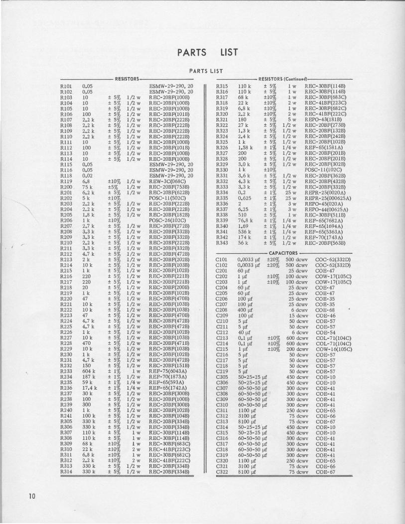
PARTS LIST
PARTS LIST RESISTORS RESISTORS (Continued)
R101 0.05 ESMW-29-290, 20 R315 llOk ± 5% 1w REC-30BF(l14B) R102 0.05 ESMW-29-290, 20 R316 UOk ± 5% 1w REC-30BF(l14B) R103 10 ± 5% 1/2 w REC-20BF(100B) R317 68 k ±10% 1w REC- 30BF(683C) R104 10 ± 5% 1/2 w REC- 20BF(100B) R318 22 k ±10% 2w REC-41BF(223C) R105 10 ± 5% 1/2 w REC-20BF(100B) R319 6.8 k ±10% 1w REC-30BF(682C) R106 100 ± 5% 1/2 w REC-20BF(101B) R320 2.2 k ±10% 2w REC-41BF(222C) R107 2.2 k ± 5% 1/2 w REC-20BF(222B) R321 180 ± 5% 5w REP0-43(1818) R108 2.2 k ± 5% 1/2 w REC- 20BF(222B) R322 27 k ± 5% 1/2 w REC- 20BF(27 3B) R109 2.2 k ± 5% 1/2 w REC- 20BF(222B) R323 1.3 k ± 5% 1/2 w REC- 20BF(132B) R110 2.2 k ± 5% 1/2 w REC- 20BF(222B) R324 2.4 k ± 5% 1/2 w REC-20BF(242B) R111 10 ± 5% 1/2 w REC- 20BF(100B) R325 1 k ± 5% 1/2 w REC- 20BF(102B) Rl12 100 ± 5% 1/2 w REC-20BF(101B) R326 1.58 k ± 1% 1/4 w REF- 65(1581A) Rl13 10 ± 5% 1/2 w REC- 20BF(100B) R327 200 ± 5% 1/2 w REC-20BF(201B) R114 10 ± 5% 1/2 w REC- 20BF(100B) R328 200 ± 5% 1/2 w REC- 20BF(201B) Rl15 0.05 ESMW-29-290, 20 R329 3.0 k ± 5% 1/2 w REC- 20BF(302B) R116 0.05 ESMW-29-290, 20 R330 1 k ±10% POSC-11(102C) RUB 0.02 ESMW-29-290, 20 R331 3.6 k ± 5% 1/2 w REC- 20BF(362B) R119 6.8 ±10% 1/2 w REW-3C(068C) R332 4.3 k ± 5% 1/2 w REC- 20BF( 432B) R200 75 k ±5% 1/2 w REC-20BF(753B) R333 3.3 k ± 5% 1/2 w REC- 20BF(332B) R201 6.2 k ± 5% 1/2 w REC- 20BF( 622B) R334 0.2 ± 1% 25w REPR-25(0020A) R202 5k ±10% POSC-11 (502C) R335 0.625 ± 1% 25 w REPR-25(000625A) R203 2.2 k ± 5% 1/2 w REC-20BF(222B) R336 2 ± 1% 3w REP0-45(020A) R204 2.2 k ± 5% l/2w REC-20BF(222B) R337 6.25 ± 1% 3w REP0-44(00625A) R205 1.8 k ± 5% 1/2 w REC-20BF(182B) R338 510 ± 5% 1w REC- 30BF(511B) R206 1 k ±10% POSC-26(102C) R339 76.8 k ± 1% 1/4 w REF-65(7682A) R207 2.7 k ± 5% 1/2 w REC- 20BF(272B) R340 1.69 ± 1% 1/4w REF-65(1694A) R208 3.3 k ± 5% 1/2 w REC- 20BF(332B) R341 536 k ± 1% 1/4 w REF- 65(5363A) R209 3.3 k ± 5% 1/2 w REC- 20BF(332B) R342 174 k ± 1% 1/2 w REF-70(1743A)
r R210 2.2 k ± 5% 1/2 w REC- 20BF(222B) R343 56 k ± 5% 1/2 w REC- 20BF(563B) R211 3.3 k ± 5% 1/2 w REC- 20BF(332B) R212 4.7 k ± 5% 1/2 w REC- 20BF( 472B) CAPACITORS R213 2k ± 5% 1/2 w REC- 20BF(202B) C101 0.0033 fJf ±20% 500 dcwv COC-62(3320) R214 10 k ± 5% 1/2 w REC- 20BF(103B) C102 0,0033 fJf ±20% 500 dcwv coc- 62(3320) R215 1k ± 5% 1/2 w REC- 20BF(102B) C201 60 fJf 25 dcwv COE-47 R216 220 ± 5% 1/2 w REC-20BF(221B) C202 1f.li ±10% 100 dcwv COW-17(105C) R217 220 ± 5% 1/2 w REC-20BF(221B) C203 1f.li ±10% 100 dcwv COW-17(105C) R218 20 ± 5% 1/2 w REC- 20BF(200B) C204 60 fJf 25 dcwv COE-47 R219 1 k ± 5% 1/2 w REC- 20BF(102B) C205 60 fJf 25 dcwv COE-47 R220 47 ± 5% 1/2 w REC-20BF(470B) C206 100 fJf 25 dcwv COE-35 R221 10 k ± 5% 1/2 w REC- 20BF(103B) C207 100 fJf 25 dcwv COE-35 R222 10 k ± 5% 1/2 w REC- 20BF(103B) C208 400 fJf 6 dcwv COE-68 R223 47 ± 5% 1/2 w REC- 20BF( 4708) C209 100f.li 15 dcwv COE-46 R224 4.7 k ± 5% 1/2 w REC- 20BF(472B) C210 5f.li 50 dcwv COE-57 R225 4.7 k ± 5% 1/2 w REC-20BF(472B) C211 5f.li 50 dcwv COE-57 R226 1 k ± 5% 1/2 w REC- 20BF(l02B) C212 40 fJf 6 dcwv COE-54 R227 10 k ± 5% 1/2 w REC- 20BF(103B) C213 0.1 fJf ±10% 600 dcwv COL-71(104C) R228 470 ± 5% 1/2 w REC-20BF(471B) C214 0,1 fJf ±10% 600 dcwv COL-71(104C) R229 10 k ± 5% 1/2 w REC- 20BF(103B) C215 1f.li ±10% 200dcwv COW-16(105C) R230 1k ± 5% 1/2 w REC- 20BF(102B) C216 5f.li 50 dcwv COE-57 R231 4,7 k ± 5% 1/2 w REC- 20BF( 472B) C217 5fl£ 50 dcwv COE-57 R232 150 ± 5% 1/2 w REC- 20BF(151B) C218 5f.li 50 dcwv COE-57 R233 604 k ± 1% 1w REF-75(6043A) C219 5fl£ 50 dcwv COE-57 R234 187 k ± 1% 1/2 w REF-70(1873A) C305 50-25-25 fJf 450 dcwv COE-10 R235 59 k ± 1% 1/4w REF-65(593A) C306 50-25-25 fJf 450 dcwv COE-10 R236 17.4 k ± 1% 1/4 w REF-65(1742A) C307 60-50-50 fl! 300dcwv COE-41 R237 30 k ± 5% 1/2 w REC-20BF(300B) C308 60-50-50 fJf 300 dcwv COE-41 R238 100 ± 5% 1/2 w REC- 20BF(100B) C309 60-50-50 fJf 300 dcwv COE-41 R239 300 ± 5% 1/2 w REC-20BF(300B) C310 60-50-50 fJf 300 dcwv COE-41 R240 1 k ± 5% 1/2 w REC- 20BF(102B) C311 1100 fJf 250 dcwv COE-65 R241 100 k ± 5% 1/2 w REC- 20BF(104B) C312 3100 fJf 75 dcwv COE-66 R305 330 k ± 5% 1/2 w REC-20BF(334B) C313 8100 fJf 75 dcwv COE-67 R306 330 k ± 5% 1/2 w REC- 20BF(334B) C314 50-25-25 fJf 450 dcwv COE-10 R307 110k ± 5% 1w REC- 30BF(ll4B) C315 50~25-25 fJf 450 dcwv COE-10 R308 UOk ± 5% 1w REC-30BF(ll4B) C316 60-50-50 fJf 300 dcwv COE-41 R309 68 k ±10% lw REC-30BF(683C) C317 60-50-50 fJf 300dcwv COE-41 R310 22 k ±10% 2w REC-41BF(223C) C318 60-50-50 flf 300dcwv COE-41 R311 6,8 k :r10% 1w REC-30BF(682C) C319 60-50-50 fJf 300 dcwv COE-41 R312 2,2 k ±10% 2w REC-41BF(222C) C320 1100 fJf 250 dcwv COE-65 R313 330 k ± 5% 1/2 w REC-20BF(334B) C321 3100 fJf 75 dcwv COE-66 R314 330 k ± 5% 1/2 w REC- 20BF(334B) C322 8100 fJf 75 dcwv COE-67
10

.. A
,-<~0
T :JOZF ....... ~ :...--' - -~~ 'o./llo\\v
:JOTFV
CONSTANT CONSTANT VOL TAG\ - CURRENT
§
AMPS VOLTS 0.5 1.6 40 125
5 400

R/19 6.8
WH-DR-8L-~b': 2W
6V P/0/ 9
o<IH-OR-GH-81(
WH-011-GH-811 WH-R0-8K
R/03 /0
R/04 /0
R/05 /0
.!f/07 ,&--2K
CR30/ CR302
~• 'lf~ ri:'... r:~: 11 25 '"I CR304 .,
.:i T.JOI,
.... 20
CR T.JOI, 211 ... ...
/7 RIO! .01
R/02 .01
R/06 100 lt'H- R0-8K 262V
• r-.._ R/08 'i \ 2 .2K rtot
f:4.A.r!aJ
M0/0/F
WH-RD-8K
• Q/01 -~ • 0103 ~/ 'RIO/
• Q/04 R/18 Q/05 ~po
I~ .02 WH-RD-GN ~ "' 'I' ~
WH-VT-GN-81( .:. .. WH·OII-811-8K l
WH-DR-BL~~K \ ). \ ~:¥~1'-1
F/0/ tl !J II -:~C/0/ :
16
j2
-~ -~s~~-~·m, R/16'---1'-R-l-15..__.... R/12 R/10
• 0106
~.JV
.01 .01 100 2.2K
A TID AT/I AT/I' ~TI.J
.0033 I
li\ Is tO! 2
"-" I o] _L I ;,-·~I R/14 R/13 Rill PLIO/ C/02-:- I I 10 10 /0
~3 I ~~'III~~,.J~~W~N~-R~D~-~8~L-~~----------J~--------~
.:: F~02 F/03 ~I .--- AT/01 ~~H-VT·GY-GN if I ~ 11 WH-GY-8R ~
WH-VT·GY-RD WH-vT-GY-8L J IQ 6 WH-VT-RD-8K ~ I ~ ..7 WH-GN-8L-8R iil
tNPI/r -:- ES8 ~ I/5/230V 50-60C AT/4
WH-VT-GY WH·VT-GN-8L FOR 115V !NPI/T CONNECT T/01-#1 TO it3 8 #2 T0-#4 \wH~Y-8L ffii' FlO/, F/02 • 5 AMPS
SPAN WH·VT-8L R20/ 11 17>
~\CR~I r0~~~0-/._~6~.N2~K~JL~A~f .• ~~
/!J r- e R§_~ WH·VT-GN
R205
C202
~~:: /JJF R209
;: 3.3K
~ ~ 1.2V
. f-./ R208 C20J .S.3K r~f
I
FOR 230V INPI/T CONNECT rtot #2ro~ F/01, F/02 • 2.5AMPS
REFERENCE REIJIILATOR R200 1·8 K
~~ ~;v'..-;, S; ,.;~~ Rff
75K 0202 WH·DR·8K
A lJ
AT8 AT4
0 CR~~
C~203 ·o
.J! f 1'),C206 C201'~T r OOpF /OOpF
1
C20/ R204~ io! CR202 C204
60p¥ 2.2K ~· Q WH-DR·8K 60pF f
AT.J WH·VT·RD . ~cw·· R206 ti(j£ IVH-GY~ IK 601-~
~-, 0203
\1?• l R212 4.7K
·~ !ott 'CR205
~210 R211 EK :J.n
AT9 OUTPUT .---- L--
~.R220 C219 R214 47 5PC.:!:. !OK 0206. __ ._.., .,
~~ ,- 05~· "Jk3 ,-;: • ~ ·~
0205 R215 IK
R218 20
R2(f: R217 220 220
R219 IK
8+ RE61/LATOR
R221 !OK
R222 /OK,_
R223
0208 • 47
Hlo'71 2.7K
C209 + /OOpF
... c/208 R221'
/01(
ATT
R224 4.7K
R226 /I(
PHASE SHIFT NETWORK
262V
12 -+
T~OIC~3,:"0 ... r~t.C-3'' .... Tjf4 ~•r;:.
ci!Jt2
S.JO
20!1 'ioi;
IIH·RD-BL-7301, B
~301,
TXI, T.JOI, r. .J4 •• .u .J
cR!tJ
CONSTANT CONSTANT VOLTAGE CURRENT
WH-011-BY
R230 fl(
IO.JR~ ~ 102R
S..'O/
• .~m~R~4-l~----~ /O!JR y • "l I -1
R23/ 12A
R228 470
hl C213 t O.l R240
+ IK
"C£:4._, Tw.r-~ +" R234
187K
C215 R?39 ~ j~7pF 3~ . I t------:t35
59K 1/~W
C216 C;ff R?.-!~~ m Hm ~H~
..... LoCR207 .... 4 6 'I ~P201 !50 -1 1~K S HIH-61'-IfD AT6 //4W
RESET WH-GY·8L WH-VT-81( ._--AM,!.!-2"'--]~
Rotary switch sections are shown as viewed from the panel end of the shaft. The first digit of the contact number refers to the section. The section nearest the panel is 1, the next section back is 2, etc. The next two digits refer to the contact. Contact 01 is the first position clockwise from a strut screw (usually the screw above the locating key), and the other contacts are numbered sequentially (02, 03, 04, etc), proceeding clockwise around the section. A suffix F or R indicates that the contact is on the front or rear of the section, respectively.
0/FFER£1'1 1 /AL AMl'LIFIER OVERLO,ID SWITCH OVERLOAD C217 1/237 A 5f,F JO
f r---------~,..6
Figure 4-2. Schematic diagram for the Type

CRJ02 TSOI. TSO' CRJ03 r.10I BR TJ:' .• 27' 2!9 .. so'
)4 ... 'I u L301
~T301, rooo: ruw rmm ~ 'Y.!-GY-GN-BR
20 4 6 II 2 I 9 ' CNI ::J ~~Til)- ltH·R0·6N·8R WH
MECHANICALLY b5
YE I N-BL •
R321 CONNECrEO ro WH·GY·RO:/!.L WH-GY-RO-BR
r3~ 180 R206 5W I OUTPUT
$.102AMP$ I ..----@oiJOI 06
"' ;-' ~ I $304 T.101
"' "' "'J ~ "'1 :i ~ ON ~ 24' C(:Jl' .... .... ~- ~
.... ~- .., ~ ~ ~ @ol302 ~-VT <! 2 ..
~ ~ ~ ll ll ;;: ll ;; ;;;
~ "' "' "' "' .. • • • 0:
"' "' ~ ~ $.102AMPS j__o/303 ....
S302AMP$ !JOIF:R WJI-GY·RO-BL $.102 AMPS ~
~ ... ~ C) ~ BR i ~ ~ .. 20/F,R .107'F J06R
• WH·GN-BR -:-• .105F.R
~0.1 VOLr$ WH-GN·BL
.102F,:1 "' "' $30.1 VOLrS .... .... 50301
~ ,. $.10.1 VOLr$
b7F.R WH-6r 205F,R WH· VT-BL·BK .10/F.R <> ;,r: ., 206F,R t t t ' 14•
$30$ 12.5 40 125 400 0.16 0.5 1.6 5 L:=-::EJ VOLr$ $30.1 VOLr$
'IOIF,R 5303 VOLTS ~ • ~ ~ 501F,R - BL
• • ur~-1 "' "' 5.103 VOLTS
~- ~- .... ~ II'H-BL-BR 40ZF.R v T f T:". Gr
S02F.R ,j ~-SO$F,R WH-YE-BL
~ ~ C) ~ () WH-GN-8/r 403F.R .. ~ WH-GY·BL-BK lttwH-BL-~K "' ;:; 503F.R ~
CR308 WH·GY-BL-BR WH-YE·BR
40/R 412F 407H 406F 50IR $.102 AMPS 4 S12F ~ 507'R $302 AMPS
506F
~ $:J02AMPS $302AMP$ c~~o $.102 AMPS $302 AMPS
s;yo2I;MPs $.102AMP
~ ; -~ 4~ ~ l ~ ~ 4~ 4!!; 4 WH-RO·BL·BK cl:
~ ~ ~ !~ t ~ II: "' • • • • • • ~ r3Dt, ' ~ "' ~ ~ ~ ~ ~ ...
~ ~ ... ~ II ~ ~ .. ~ ~ ~ ~~ ~ -~ ~ ~ ., ll ., iii r-~ ~ ~701, ~ .. ~
WH-GY-BK ~ 'I:• T#l, ~:ffl, ~f':._. rso1, J2 WH-rE-vr
rr,z ~3 C~4 I¥H-VY-6Y·BK
WH·YE·OR "'H·6Y·BR-BK RO
WH-VT·BR l \wN-VY·RD-BL WH·YE-BK GN
~~ lfH·Vr-RO-Q ,/ ~H-l'E-GY -ltr- - ~ r-< ,--<
,-~ T ""[]" . ~~ ~o6 ~o~1 C.105 f' C.107;;;j'
~~~~ + + C314 ;;;r:; C316 C318 + C31!9 + C320 + CJ21 C322 + A,B,C ABC
""[]"[' c.n;r: wii' C313 ;;;r:; A,B,/~1' A,76gpJ' A,'t?f' A,B,~jf' IIDOpF;'F .1JOOpF;;:;: IIJO~F;F /OOpF it/ojN' J60pF
RJ/3 ~SIS J60p lliDJIF
R305 /t.107 CS/0 1/DOpF :JI~F IIJOOpF ~.1.10~ ~ A,B,C r3.10K D ~ 1/0K,f!
c'fO'i" =Ct.+ 160pF ft "" "+ A,B,C
C.108 f'; R:J/0 R:J/1 R312 c:J/!1 --=;. C3J7
R317 R3111 RS/!9 R320 :t:J;F
R30!9 22K 6.8K 2,2K fb'ftF 1~;F 61/K 22K 6.1/K 2.2K l60pF 68K
RS08 R.1011 IW 2W IW 2W /t:S/4 ~:1/6 JW 2W IW 2W 3.10K 1/0K,/W BL 3.10K 1/0KIW
o/301 o/302
!!!- R233 M301 WH·Vr-BR·BK
0 -, R34:S RJ22 604K
56K 27'K MJ02 .nWH-O,f-BL
BL V +tl. 0 IW W1HJR-GN :.1 + f!'!!· R:J39 0 8L 811
C21J $30:1, 10/R .! /UJO sso(foTR 1'6.8K ~5 R3:SI I/4W COLL n R240 WH-OR-BR IK 3.6K BA
IK R325 R340 Q/0.1, Q/011
* IK 1.69M
~ R326 R327' 1/IF-IIZF I/4W I l58K 200 ils ~ ~ RJ41 BASE
R234 ~ I/4W 5:S6K
EM i;:).COLL
187'K :1: S:SOJ,I04R S! ~ s:! 1.-4W
~ ~ ~ R239F ~ IOZF j 4 I $:102 AMPS
5 ~~ZJ RB~ R342 r ........ :::: pF :JOO
r
~ 17'4K $.10.1 VOLrS
R»6 ------< "' ~~ 1'-- 112F Ql04, Q/05 R235
., Q/0!9, Q/10 591( 2
102R4 ~ ' !! 114W I WH·VT-BL-BR /OW rXJp9 WH-YE·RD ... JOTF • • • Q201 THRIJQ210
'4f8 R238 l.,T 1!9 W~H;Y-GN-BL
'WII·OR·VT 10111 5F IK T r.JOt, 41 WH-'rE·GN I WH-RO-BL·BR
.,.1\ /123~ ~ "' "' R:JJl r:JOI,•o $.102 AMPS
RJJ8 I . . ~21/F '"' 1-f ' : ~ 6.25 10611 s~o;_v'!!!.! JO?R
~ ~ "' 114W 508,~ 3W It: ~ ~ :3 ~ <> ~ 510 rs.103 VOLTS r f. ' RJJJ 3.:SIC
IW $.10211MPS
RfJl AT/II '507'R ~ 102R
. R.J29 :JK 20!9F 207'F '"9-•M< WHGN-BL-Bit WH - OR-RD ~ R:J24 2.4K . RJ23 1.3K CDLL-
RJ35 0.625 25W WH-BL Q/01, Q/01
R3J4 02,25W Q/06, Q/07'
WH-BR
!r the Type 1265-A Adjustable DC Power Supply. POSITION OF ROTARY SWITCHES SHOWN COUNTERCLOCKWISE.
REFER TO SERVICE NOTES IN INSTRUCTION BOOK FOR VOLTAGES APPEARING ON DIAGRAM.
RESISTORS 1/2 WATT.
RESISTANCE IN OHMS K =1000 OHMS M =1 MEGOHM
CAPACITANCE VALUES ONE AND OVER IN PICOFARADS, LESS THAN ONE IN MICROFARADS.
Q KNOB CONTROL @ SCREWDRIVER CONTROL
AT =ANCHOR TERMINAL 11 TP =TEST POINT -
L_

c
C204
C205
Figure 4·3. Etched board layout for the Type 1265-A Adjustable DC Power Supply.
WKDST
12
"'<t' -0 0 ,.._ 0
. I
C215
I

GENERAL RADIO COMPA v WEST CONCORD, MASSACHUSETTS
EMerson 9-4400 Mission 6-7400
D I 5 T R.l C T
NEW YORK* Broad Avenue at Linden Ridgefield, New Je rsey Telephone N .Y. WOrth 4 -2722
N.J. WHitney 3-3140
SYRACUSE Pickard Building East Molloy Road Syracuse 11, New York Telephone GLenview 4-9323
PHILADELPHIA
1150 York Road Abington, Pennsylvania Telephone TUrner 7-8486
Philo ., HAncock4-7419
WASHINGTON* Rockville Pike at Wall Lane Rockville, Maryland Telephone 946-1600
CHICAGO* 6605 West North Avenue Oak Park, Illinois Telephone VIllage 8-9400
• Repair services are available at these district offices .
OFFICES
LOS ANGELES*
1 000 North Seward Street Los Angeles 38, California Telephone HOllywood 9-6201
SAN FRANCISCO
1186 Los Altos Avenue Los Altos, California Telephone WHitecliff 8-8233
DALLAS
2501-A West Mockingbird Lane Dallas 35, Texas Telephone FLeetwood 7-4031
FLORIDA
11 3 East Drive Orlando, Florida Telephone GArden 5-4671
CANADA* 99 Floral Parkway Toronto 15, Ontario Telephone CHerry 6-2171
* Repair services are available at these district offices .
General Radio Company (Overseas), Zurich, Switzerland Representatives in Principal Overseas Countries Pr inted in USA