ademco vista series - honeywell thermostat manual pdf · ademco vista series vista-20p /...
TRANSCRIPT
ADEMCO VISTA SERIES
VISTA-20P / VISTA-20PSIA VISTA-15P / VISTA-15PSIA
Security Systems
Programming Guide
K5305-1PRV5 10/04 Rev. A
Downloaded from www.Manualslib.com manuals search engine

TO ENTER PROGRAMMING MODE (using an alpha keypad connected to the control): A. POWER UP, then press [✱] and [#] at the same time, within 50 seconds of powering up (this method must be used if ✱98
was used to exit program mode). OR B. Initially, key: Installer Code (4 + 1 + 1 + 2) plus 8 + 0 + 0.
PROGRAMMING MODE COMMANDS Task Command/Explanation Go to a Data Field Press [∗∗∗∗] + [Field Number], followed by the required entry. Entering Data When the desired field number appears, simply make the required entry. When the last entry
for a field is entered, the keypad beeps three times and automatically displays the next data field in sequence. If the number of digits that you need to enter in a data field is less than the maximum digits available (for example, the phone number fields *41, *42), enter the desired data, then press [∗ ] to end the entry. The next data field number is displayed.
Review a Data Field Press [#] + [Field Number]. Data will be displayed for that field number. No changes will be accepted in this mode.
Deleting an Entry Press [∗∗∗∗] + [Field Number] + [∗∗∗∗]. (Applies only to fields ∗40 thru *46, *94, and pager fields) Initialize Download ID Press ∗∗∗∗96. Initializes download ID and subscriber account number. Reset Factory Defaults Press ∗∗∗∗97. Sets all data fields to original factory default values. Zone Programming Press ∗∗∗∗56. Zone characteristics, report codes, alpha descriptors, and serial numbers for 5800
RF transmitters. Function Key Programming Press ∗∗∗∗57. Unlabeled keypad keys (known as ABCD keys) for special functions Zone Programming (Expert Mode)
Press ∗∗∗∗58. Same options as *56 mode, but with fewer prompts. Intended for those familiar with this type of programming, otherwise *56 mode is recommended.
Output Device Mapping Press ∗∗∗∗79. Assign module addresses and map individual relays/powerline carrier devices Output Programming Press ∗∗∗∗80. 4229 or 4204 Relay modules, Powerline Carrier devices, or on-board triggers Zone List Programming Press ∗∗∗∗81. Zone Lists for relay/powerline carrier activation, chime zones, pager zones, etc. Alpha Programming Press ∗∗∗∗82. Zone alpha descriptors Exit Program Mode with installer code lockout
Press ∗∗∗∗98. Exits programming mode and prevents re-entry by: Installer Code + 8 + 0 + 0. To reenter programming mode, the system must be powered down, then powered up. Then use method A above. See field *88 for other *98 Program mode lockout options.
Exit Program Mode Press ∗∗∗∗99. Exits programming mode and allows re-entry by: Installer Code + 8 + 0 + 0 or method A above.
SPECIAL MESSAGES OC = OPEN CIRCUIT (no communication between Keypad and Control). EE or ENTRY ERROR = ERROR (invalid field number entered; re-enter valid field number). After powering up, AC, dI (disabled) or Busy Standby and NOT READY will be displayed after approximately 4 seconds. This will revert to a “Ready” message in approximately 1 minute, which allows PIRS, etc. to stabilize. You can bypass this delay by pressing [#] + [0]. If E4 or E8 appears, more zones than the expansion units can handle have been programmed. The display will clear after you correct the programming.
TABLE OF DEVICE ADDRESSES This Device Uses Address Reports as †† Enabled By… RF Receiver 00 100 *56 zone programming: input device type entry AUI 1 01 101 Automatic if AUI enable field *189 enabled for AUI 1 AUI 2 02 102 Automatic if AUI enable field *189 enabled for AUI 2 Long Range Radio 03 103 automatic if output to long range radio field *29 enabled 4286 Voice Module 04 104 automatic if phone module access code field *28 enabled Zone Expanders (4219/4229):
module 1 (for zones 09 - 16)module 2 (for zones 17 - 24)module 3 (for zones 25 - 32)module 4 zones 33 - 40 module 5 zones 41 - 48
07 08
09** 10** 11**
107 108 109 110 111
*56 zone programming: input device type entry, then: automatic if zone no. 9-16 entered as AW type or relay assigned automatic if zone no. 17-24 entered as AW type or relay assigned automatic if zone no. 25-32 entered as AW type or relay assigned automatic if zone no. 33-40 entered as AW type or relay assigned automatic if zone no. 41-48 entered as AW type or relay assigned
Relay Modules (4204): module 1 module 2 module 3 module 4
12 13
14** 15**
112 113 114 115
*79 output device programming: device address prompt: entered at device address prompt entered at device address prompt entered at device address prompt entered at device address prompt
Keypads: keypad 1 keypad 2 keypad 3 keypad 4 keypad 5 keypad 6 keypad 7 keypad 8
16 17 18 19 20 21 22 23
n/a n/a n/a n/a n/a n/a n/a n/a
data field programming as listed below: always enabled, all sounds enabled. data field *190 data field *191 data field *192 data field *193 data field *194 data field *195 data field *196
5800TM Module 28 n/a automatic
** These module addresses apply to VISTA-20P only. †† Addressable devices are identified by “1” plus the device address when reporting. Enter report code for zone 91 to enable addressable device
reporting (default = reports enabled). See field *199 for addressable device (ECP) 3-digit/2-digit identification keypad display options.
– 2 –
Downloaded from www.Manualslib.com manuals search engine
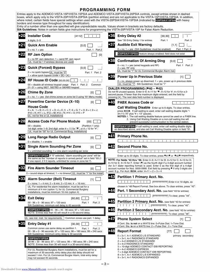
PROGRAMMING FORM Entries apply to the ADEMCO VISTA-15P/VISTA-15PSIA and ADEMCO VISTA-20P/VISTA-20PSIA controls, except entries shown in dashed boxes, which apply only to the VISTA-20P/VISTA-20PSIA (partition entries) and are not applicable to the VISTA-15P/VISTA-15PSIA. In addition, where noted, certain fields have special settings when used with the VISTA-20PSIA/VISTA-15PSIA (indicated by V20PSIA/V15PSIA with heavy borders and reverse type throughout for easy identification). Entry of a number other than one specified will give unpredictable results. Values shown in brackets are factory defaults. SIA Guidelines: Notes in certain fields give instructions for programming the VISTA-20P/VISTA-15P for False Alarm Reduction.
∗∗∗∗20 Installer Code [4112] | | | 4 digits, 0–9
∗∗∗∗21 Quick Arm Enable [0,0]
0 = no; 1 = yes Part. 1 Part.2
∗∗∗∗22 RF Jam Option [0]
0 = no RF Jam detection; 1 = send RF Jam report UL: must be 1 if wireless devices are used
∗∗∗∗23 Quick (Forced) Bypass [0,0]
0 = no quick bypass UL: must be “0” Part. 1 Part. 2 1 = allow quick bypass (code + [6] + [#] )
∗∗∗∗24 RF House ID Code [00,00,00] | | |
00 = disable all wireless keypad usage Part. 1 Part. 2 Common 01–31 = using 5827, 5827BD or 5804BD keypad
∗∗∗∗26 Chime By Zone [0]
0 = no; 1 = yes (list chime zones on zone list 3 using *81 Menu mode)
∗∗∗∗27 Powerline Carrier Device (X–10) [0]
House Code 0 = A; 1 = B; 2 = C; 3 = D; 4 = E; 5 = F; 6 = G; 7 = H; 8 = I; 9 = J;
#10 = K; #11 = L; #12 = M; #13 = N; #14 = O; #15 = P UL: not for fire or UL installations
∗∗∗∗28 Access Code For Phone Module [00] | 00 = disable; (Partition 1 only) 1st digit: enter 1–9; 2nd digit: enter # + 11 for "✱", or # + 12 for "#". UL: must be “00” for UL Commercial Burg. installations
∗∗∗∗29 Long Range Radio Output [0] 0 = disable; 1 = enable
∗∗∗∗31 Single Alarm Sounding Per Zone [0] 0 = unlimited sounding; 1 = one alarm sounding per zone
V20PSIA/V15PSIA: If “0” selected, “alarm sounding per zone” will be the same as the “number of reports in armed period” set in field *93 (1 if one report, 2 if 2 reports, unlimited for zones in zone list 7).
∗∗∗∗32 Fire Alarm Sounder Timeout [0]
0 = sound stops at timeout; 1 = no timeout UL: must be “1” for fire install.
∗∗∗∗33 Alarm Sounder (Bell) Timeout [1] 0 = none; 1 = 4 min; 2 = 8 min; 3 =12 min; 4 = 16 min;
UL: For residential fire alarm installation, must be set for a minimum of 4 min (option 1); for UL Commercial Burglary installations, must be minimum 16 min (option 4)
∗∗∗∗34 Exit Delay [60,60] | |
00 - 96 = 0 - 96 secs; 97 = 120 secs Part. 1 Part. 2 SIA Guidelines: minimum exit delay is 45 seconds
V20PSIA/V15PSIA: 45 - 96 = 45 - 96 secs; 97 = 120 secs NOTE: Entries less than 45 will result in a 45-second delay.
UL: see inst. instr. for requirements. Common zones use part. 1 delay.
∗∗∗∗35 Entry Delay #1 [30,30] | |
Common zones use same delay as partition 1. Part. 1 Part. 2 00 - 96 = 0 - 96 seconds; 97 = 120 secs; 98 = 180 secs; 99 = 240 secs SIA Guidelines: minimum entry delay is 30 seconds
V20PSIA/V15PSIA: 30-96 = 30 - 96 secs; 97 = 120 secs; 98 = 180 secs; 99 = 240 secs NOTE: Entries less than 30 will result in a 30-second delay.
For UL Residential Burglary Alarm installations, must be set for a maximum of 30 seconds; entry delay plus dial delay should not exceed 1 min. For UL Commercial Burglar Alarm, total entry delay may not exceed 45 seconds.
∗∗∗∗36 Entry Delay #2 [30,30] | |
See *35 Entry Delay 1 for entries. Part. 1 Part. 2 ∗∗∗∗37 Audible Exit Warning [1,1] 0 = no; 1 = yes (SIA Guidelines: must be enabled) Part. 1 Part. 2
V20PSIA/V15PSIA: feature always enabled; field does not exist
∗∗∗∗38 Confirmation Of Arming Ding [0,0]
0 = no; 1 = yes (wired keypads and RF) Part. 1 Part. 2 2 = yes, RF only UL: must be “1” for UL Commercial Burglar Alarm inst.
∗∗∗∗39 Power Up In Previous State [1] 0 = no, always power up disarmed; 1 = yes, power up in previous state UL: must be “1” SIA Guidelines: must be “1”
DIALER PROGRAMMING (✱40 – ✱42) Do not fill unused spaces. Enter 0–9; #+11 for '✱'; #+12 for '#'; #+13 for a 2-second pause. If fewer than the maximum digits entered, exit the field by pressing [✶]. The next data field number is displayed.
∗∗∗∗40 PABX Access Code or | | | | |
Call Waiting Disable Enter up to 6 digits. To clear entries, press ✱40✱. If call waiting is used, enter call waiting disable digits “∗ (#+11) 70” plus “# + 13” (pause). NOTES: 1. The call waiting disable feature cannot be used on a PABX line.
2. Using Call Waiting Disable on a non-call waiting line will prevent successful communication to the central station.
V20PSIA/V15PSIA: If call waiting is used, enter call waiting disable digits as described above, and also set Call Waiting Disable option in field *91.
∗∗∗∗41 Primary Phone No. | | | | | | | | | | | | | | | | | | |
∗∗∗∗42 Second Phone No. | | | | | | | | | | | | | | | | | | | Enter up to 20 digits. To clear entries, press ✱41✱ or ✱42✱ respectively.
NOTE: For fields *43 thru *46: Enter 0–9; #+11 for B; #+12 for C; #+13 for D; #+14 for E; #+15 for F. Enter [✱] as the fourth digit if a 3-digit account number (for 3+1 dialer reporting format) is used. Enter 0 as the first digit of a 4-digit account number for Nos. 0000-0999. Exit field by pressing ✱ if only 3 digits are used. E.g., For Acct. B234, enter: #+11 + 2 + 3 + 4
∗∗∗∗43 Partition 1 Primary Acct. No. | | | / | | | | | [FFFFFFFFFF] Enter 4 or 10 digits, as
chosen in *48 Report Format. See box above. To clear entries, press *43*.
∗∗∗∗44 Part. 1 Secondary Acct. No. (see field *43 for entries)
| | | / | | | | | [FFFFFFFFFF] To clear, press *44*.
∗∗∗∗45 Partition 2 Primary Acct. No. (see field *43 for entries) | | | / | | | | | [FFFFFFFFFF] To clear, press *45*.
∗∗∗∗46 Partition 2 Secondary Acct. No. (see field *43 for entries) | | | / | | | | | [FFFFFFFFFF] To clear, press *46*.
∗∗∗∗47 Phone System Select [1]
If Cent. Sta. is not on a WATS line: 0=Pulse Dial; 1=Tone Dial; if Cent. Sta. is on a WATS line: 2 = Pulse Dial ; 3 = Tone Dial
∗∗∗∗48 Report Format [77] 0 = 3+1, 4+1 ADEMCO L/S STANDARD primary secondary 1 = 3+1, 4+1 RADIONICS STANDARD 2 = 4+2 ADEMCO L/S STANDARD 3 = 4+2 RADIONICS STANDARD 5 = 10-digit ADEMCO CONTACT ID® REPORTING 6 = 4+2 ADEMCO EXPRESS 7 = 4-digit ADEMCO CONTACT ID® REPORTING 8 = 3+1, 4+1 ADEMCO L/S EXPANDED 9 = 3+1, 4+1 RADIONICS EXPANDED
– 3 –
Downloaded from www.Manualslib.com manuals search engine
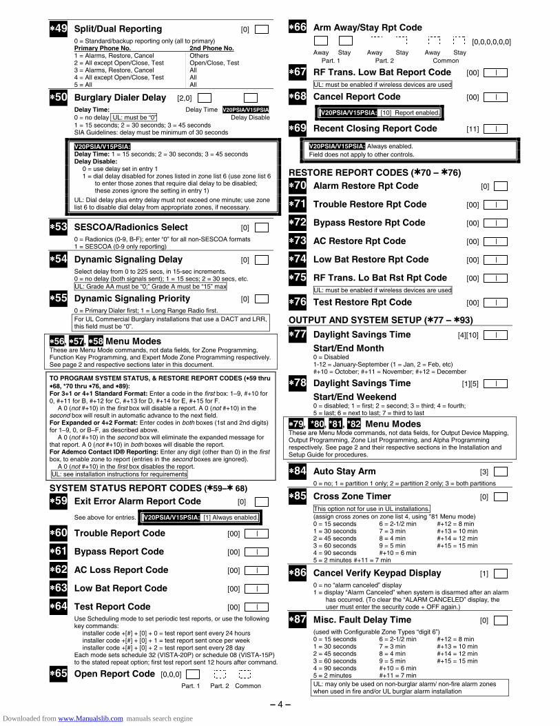
∗∗∗∗49 Split/Dual Reporting [0]
0 = Standard/backup reporting only (all to primary) Primary Phone No. 2nd Phone No. 1 = Alarms, Restore, Cancel Others 2 = All except Open/Close, Test Open/Close, Test 3 = Alarms, Restore, Cancel All 4 = All except Open/Close, Test All 5 = All All
∗∗∗∗50 Burglary Dialer Delay [2,0]
Delay Time: Delay Time V20PSIA/V15PSIA 0 = no delay UL: must be “0” Delay Disable 1 = 15 seconds; 2 = 30 seconds; 3 = 45 seconds
SIA Guidelines: delay must be minimum of 30 seconds
V20PSIA/V15PSIA: Delay Time: 1 = 15 seconds; 2 = 30 seconds; 3 = 45 seconds Delay Disable: 0 = use delay set in entry 1 1 = dial delay disabled for zones listed in zone list 6 (use zone list 6
to enter those zones that require dial delay to be disabled; these zones ignore the setting in entry 1)
UL: Dial delay plus entry delay must not exceed one minute; use zone list 6 to disable dial delay from appropriate zones, if necessary.
∗∗∗∗53 SESCOA/Radionics Select [0] 0 = Radionics (0-9, B-F); enter “0” for all non-SESCOA formats 1 = SESCOA (0-9 only reporting)
∗∗∗∗54 Dynamic Signaling Delay [0]
Select delay from 0 to 225 secs, in 15-sec increments. 0 = no delay (both signals sent); 1 = 15 secs; 2 = 30 secs, etc. UL: Grade AA must be “0;” Grade A must be “15” max
∗∗∗∗55 Dynamic Signaling Priority [0]
0 = Primary Dialer first; 1 = Long Range Radio first. For UL Commercial Burglary installations that use a DACT and LRR, this field must be “0”.
∗∗∗∗56, ∗∗∗∗57, ∗∗∗∗58 Menu Modes These are Menu Mode commands, not data fields, for Zone Programming, Function Key Programming, and Expert Mode Zone Programming respectively. See page 2 and respective sections later in this document.
TO PROGRAM SYSTEM STATUS, & RESTORE REPORT CODES (∗∗∗∗59 thru ∗∗∗∗68, *70 thru ∗∗∗∗76, and ∗∗∗∗89): For 3+1 or 4+1 Standard Format: Enter a code in the first box: 1–9, #+10 for 0, #+11 for B, #+12 for C, #+13 for D, #+14 for E, #+15 for F. A 0 (not #+10) in the first box will disable a report. A 0 (not #+10) in the second box will result in automatic advance to the next field. For Expanded or 4+2 Format: Enter codes in both boxes (1st and 2nd digits) for 1–9, 0, or B–F, as described above. A 0 (not #+10) in the second box will eliminate the expanded message for that report. A 0 (not #+10) in both boxes will disable the report. For Ademco Contact ID® Reporting: Enter any digit (other than 0) in the first box, to enable zone to report (entries in the second boxes are ignored). A 0 (not #+10) in the first box disables the report. UL: see installation instructions for requirements
SYSTEM STATUS REPORT CODES (✱59–✱ 68)
∗∗∗∗59 Exit Error Alarm Report Code [0]
See above for entries. V20PSIA/V15PSIA: [1] Always enabled.
∗∗∗∗60 Trouble Report Code [00] |
∗∗∗∗61 Bypass Report Code [00] |
∗∗∗∗62 AC Loss Report Code [00] |
∗∗∗∗63 Low Bat Report Code [00] |
∗∗∗∗64 Test Report Code [00] |
Use Scheduling mode to set periodic test reports, or use the following key commands:
installer code +[#] + [0] + 0 = test report sent every 24 hours installer code +[#] + [0] + 1 = test report sent once per week installer code +[#] + [0] + 2 = test report sent every 28 day Each mode sets schedule 32 (VISTA-20P) or schedule 08 (VISTA-15P)
to the stated repeat option; first test report sent 12 hours after command.
∗∗∗∗65 Open Report Code [0,0,0]
Part. 1 Part. 2 Common
∗∗∗∗66 Arm Away/Stay Rpt Code [0,0,0,0,0,0]
Away Stay Away Stay Away Stay Part. 1 Part. 2 Common
∗∗∗∗67 RF Trans. Low Bat Report Code [00] |
UL: must be enabled if wireless devices are used
∗∗∗∗68 Cancel Report Code [00] |
V20PSIA/V15PSIA: [10] Report enabled.
∗∗∗∗69 Recent Closing Report Code [11] |
V20PSIA/V15PSIA: Always enabled. Field does not apply to other controls.
RESTORE REPORT CODES (✱70 – ✱76) ∗∗∗∗70 Alarm Restore Rpt Code [0]
∗∗∗∗71 Trouble Restore Rpt Code [00] |
∗∗∗∗72 Bypass Restore Rpt Code [00] |
∗∗∗∗73 AC Restore Rpt Code [00] |
∗∗∗∗74 Low Bat Restore Rpt Code [00] |
∗∗∗∗75 RF Trans. Lo Bat Rst Rpt Code [00] |
UL: must be enabled if wireless devices are used
∗∗∗∗76 Test Restore Rpt Code [00] |
OUTPUT AND SYSTEM SETUP (✱77 – ✱93)
∗∗∗∗77 Daylight Savings Time [4][10] |
Start/End Month 0 = Disabled 1-12 = January-September (1 = Jan, 2 = Feb, etc) #+10 = October; #+11 = November; #+12 = December
∗∗∗∗78 Daylight Savings Time [1][5] |
Start/End Weekend 0 = disabled; 1 = first; 2 = second; 3 = third; 4 = fourth; 5 = last; 6 = next to last; 7 = third to last
∗∗∗∗79, *80, *81, *82 Menu Modes These are Menu Mode commands, not data fields, for Output Device Mapping, Output Programming, Zone List Programming, and Alpha Programming respectively. See page 2 and their respective sections in the Installation and Setup Guide for procedures.
∗∗∗∗84 Auto Stay Arm [3] 0 = no; 1 = partition 1 only; 2 = partition 2 only; 3 = both partitions
∗∗∗∗85 Cross Zone Timer [0] This option not for use in UL installations. (assign cross zones on zone list 4, using *81 Menu mode) 0 = 15 seconds 6 = 2-1/2 min #+12 = 8 min 1 = 30 seconds 7 = 3 min #+13 = 10 min 2 = 45 seconds 8 = 4 min #+14 = 12 min 3 = 60 seconds 9 = 5 min #+15 = 15 min 4 = 90 seconds #+10 = 6 min 5 = 2 minutes #+11 = 7 min
∗∗∗∗86 Cancel Verify Keypad Display [1] 0 = no “alarm canceled” display 1 = display “Alarm Canceled” when system is disarmed after an alarm
has occurred. (To clear the “ALARM CANCELED” display, the user must enter the security code + OFF again.)
∗∗∗∗87 Misc. Fault Delay Time [0] (used with Configurable Zone Types “digit 6”) 0 = 15 seconds 6 = 2-1/2 min #+12 = 8 min 1 = 30 seconds 7 = 3 min #+13 = 10 min 2 = 45 seconds 8 = 4 min #+14 = 12 min 3 = 60 seconds 9 = 5 min #+15 = 15 min 4 = 90 seconds #+10 = 6 min 5 = 2 minutes #+11 = 7 min
UL: may only be used on non-burglar alarm/ non-fire alarm zones when used in fire and/or UL burglar alarm installation
– 4 –
Downloaded from www.Manualslib.com manuals search engine

∗∗∗∗88 Program Mode Lockout Options [0] 0 = standard *98 installer code lockout (reentry only by [∗] + [#] within
50 seconds after power up) 1 = lockout [∗] + [#] reentry after *98 exit (reenter via installer code or
downloader only) 2 = not used 3 = lockout local programming after *98 exit (reenter by downloader only)
∗∗∗∗89 Event Log Full Report Code [00] | See box above field *59 for report code entries.
∗∗∗∗90 Event Log Enables [3] NOTE: System messages are logged when any non-zero entry is made. 0 = None; 1 = Alarm/Alarm Restore 2 = Trouble/Trouble Restore; 4 = Bypass/Bypass Restore; 8 = Open/Close. Example: To select “Alarm/Alarm Restore”, and
“Open/Close”, enter 9 (1 + 8); To select all, enter #15.
∗∗∗∗91 Option Selection [8, 0]
Options: 0 = None Options V20PSIA/V15PSIA 4 = AAV UL: must use ADEMCO UVCM module Call Wait Disable
8 = Exit Delay Restart/Reset UL: must be disabled #+12 = AAV and Exit Delay Restart/Reset SIA Guidelines: Exit Delay should be enabled.
V20PSIA/V15PSIA: Options: Same as listed above. Call Waiting Disable: 0 = call waiting not used 1 = call waiting disable digits (*70) entered in field *40; (when
selected, the system dials the entry in field *40 only on alternate dial attempts; this allows proper dialing in the event call waiting service is later canceled by the user).
∗∗∗∗92 Phone Line Monitor Enable [0,0]
UL: see Inst. Instructions for requirements 1 2 NOTE: Output Device must either be programmed to be STOPPED in field ✱80 or STOPPED by Code + # + 8 + output number.
Entry 1:: 0 = disabled, 1-15 = 1 min - 15 min (#+10 = 10 min; #+11 = 11 min; #+12 = 12 min; #+13 = 13 min; #+14
= 14 min; #+15 = 15 min) Entry 2: 0 = Keypad display when line is faulted 1 = Keypad display plus keypad trouble sound 2 = Same as “1”, plus programmed output device STARTS. If either
partition is armed, external sounder activates also.
∗∗∗∗93 Reports In Armed Period [1,0]
Per Zone (Swinger Suppression) Restrict V20PSIA/V15PSIA Restrict Report Pairs: Report Pairs Unlimited 0 = Unlimited Reports Reports Enable 1 = 1 report pair 2 = 2 report pairs SIA Guidelines: Must be set for option 1 or 2.
V20PSIA/V15PSIA: Restrict Report Pairs: 1 = 1 report pair; 2 = 2 report pairs Unlimited Reports Enable: 0 = restrict reports to the setting in entry 1 1 = unlimited reports for zones listed in zone list 7; (use zone list 7
to enter those zones that require unlimited reporting; these zones ignore the setting in entry 1)
DOWNLOAD INFORMATION (✱94, ✱95) ∗∗∗∗94 Download Phone No. | | | | | | | | | | | | | | | | | | |
Enter up to 20 digits, 0–9; #+11 for '✱'; #+12 for '#'; #+13 for a 2-second pause. Do not fill unused spaces. If fewer than 20 digits, exit field by pressing ✱. To clear entries from field, press ✱94✱.
UL: downloading may be performed only if a technician is at the site.
∗∗∗∗95 Ring Count For Downloading [15]
NOTE: Do not enter “0” if using 4285/4286 Phone Module. 0 = Disable Station Initiated Download; 1–14 = number of rings (1–9, # +10 =10, # +11 =11, # +12 =12, # +13 =13, # +14 =14); 15 = answering machine defeat (# +15 =15).
∗∗∗∗96, ∗∗∗∗97 Initialize/Reset Defaults This is a command, not a data field. See page 2.
∗∗∗∗98, *99 Exit Commands This is a command, not a data field. See page 2.
PAGER OPTIONS (✱160- ✱172) ∗∗∗∗160 Pager 1 Phone No. | | | | | | | | | | | | | | | | | | |
Enter up to 20 digits. 0–9; #+11 = '✱'; #+12 = '#'; #+13 = 2-sec pause
∗∗∗∗161 Pager 1 Characters
| | | | | | | | | | | | | | |
Enter the optional prefix characters, up to 16 digits. 0–9; #+11 = '✱'; #+12 = '#'; #+13 = 2-second pause.
∗∗∗∗162 Pager 1 Report Options
[0,0,0]
Part. 1 Part. 2 common For each partition, select from the following options: 0 = no reports sent 1 = Opens/closes all users 4 = All alarms and troubles 5 = All alarms / troubles, and opens/closes for all users 12 = Alarms / troubles for zones entered in zone list 9 13 = Alarms / troubles for zones entered in zone list 9, and
opens/closes for all users
∗∗∗∗163 Pager 2 Phone No. | | | | | | | | | | | | | | | | | | |
Enter up to 20 digits. 0–9; #+11 = 'Q'; #+12 = '#'; #+13 = 2-sec pause
∗∗∗∗164 Pager 2 Characters
| | | | | | | | | | | | | | |
Enter the optional prefix characters, up to 16 digits. 0–9; #+11 = '✱'; #+12 = '#'; #+13 = 2-second pause.
∗∗∗∗165 Pager 2 Report Options
[0,0,0]
Part. 1 Part. 2 common See field *162 for reporting options. Select for each partition (use zone
list 10 if using options 12 or 13).
∗∗∗∗166 Pager 3 Phone No. | | | | | | | | | | | | | | | | | | | Enter up to 20 digits. 0–9; #+11 = '✱'; #+12 = '#'; #+13 = 2-sec pause
∗∗∗∗167 Pager 3 Characters | | | | | | | | | | | | | | | Enter the optional prefix characters, up to 16 digits. 0–9; #+11 = '✱'; #+12 = '#'; #+13 = 2-second pause.
∗∗∗∗168 Pager 3 Report Options 0,0,0] Part. 1 Part. 2 common See field *162 for reporting options. Select for each partition (use zone
list 11 if using options 12 or 13).
∗∗∗∗169 Pager 4 Phone No. | | | | | | | | | | | | | | | | | | | Enter up to 20 digits. 0–9; #+11 = '✱'; #+12 = '#'; #+13 = 2-sec pause
∗∗∗∗170 Pager 4 Characters | | | | | | | | | | | | | | | Enter the optional prefix characters, up to 16 digits. 0–9; #+11 = '✱'; #+12 = '#'; #+13 = 2-second pause.
∗∗∗∗171 Pager 4 Report Options [0,0,0] Part. 1 Part. 2 common See field *162 for reporting options. Select for each partition (use zone
list 12 if using options 12 or 13).
∗∗∗∗172 Pager Delay Option For Alarms [3]
0 = none; 1 = 1 minute; 2 = 2 minutes; 3 = 3 minutes This delay is for ALL pagers in the system.
– 5 –
Downloaded from www.Manualslib.com manuals search engine
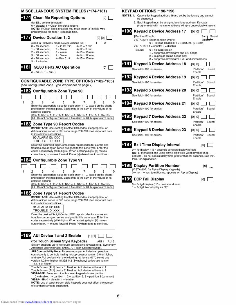
MISCELLANEOUS SYSTEM FIELDS (*174-*181)
∗∗∗∗174 Clean Me Reporting Options [0] (for ESL smoke detectors) 0 = disable; 1 = Clean Me signal reports; NOTE: If Clean Me is enabled, you must enter “3” in field ✱56
programming for zone 1 response time.
∗∗∗∗177 Device Duration 1, 2 [0] [0]
(used in *80 Menu mode-Device Actions 5/6) 1 2 0 = 15 seconds 6 = 2-1/2 min #+11 = 7 min 1 = 30 seconds 7 = 3 min #+12 = 8 min 2 = 45 seconds 8 = 4 min #+13 = 10 min 3 = 60 seconds 9 = 5 min #+14 = 12 min 4 = 90 seconds #+10 = 6 min #+15 = 15 min 5 = 2 minutes
∗∗∗∗181 50/60 Hertz AC Operation [0]
0 = 60 Hz; 1 = 50 Hz
CONFIGURABLE ZONE TYPE OPTIONS (*182-*185) (see Configurable Zone Type Worksheet on page 7)
∗∗∗∗182 Configurable Zone Type 90
1 2 3 4 5 6 7 8 9 10 Enter the appropriate value for each entry, 1-10, based on the charts provided on the next page. Each entry is the sum of the values of its selected options
(0-9, #+10=10, #+11=11, #+12=12, #+13=13, #+14=14, #+15=15). UL: Do not configure zones as a fire alarm or UL burglar alarm zone.
∗∗∗∗183 Zone Type 90 Report Codes IMPORTANT: Use existing Contact ID® codes, if appropriate, or define unique codes in CID code range 750-789. See important note in installation instructions.
90 ALARM ID: XXX TROUBLE ID: XXX
Enter the desired 3-digit Contact ID® report codes for alarms and troubles occurring on zones assigned to this zone type. Enter the codes sequentially (all 6 digits). When entering digits, [#] moves cursor back, [∗] moves forward. Press [∗] when done to continue.
∗∗∗∗184 Configurable Zone Type 91
1 2 3 4 5 6 7 8 9 10 Enter the appropriate value for each entry, 1-10, based on the charts provided on the next page. Each entry is the sum of the values of its selected options
(0-9, #+10=10, #+11=11, #+12=12, #+13=13, #+14=14, #+15=15). UL: Do not configure zones as a fire alarm or UL burglar alarm zone.
∗∗∗∗185 Zone Type 91 Report Codes IMPORTANT: Use existing Contact ID® codes, if appropriate, or define unique codes in CID code range 750-789. See important note in installation instructions.
91 ALARM ID: XXX TROUBLE ID: XXX
Enter the desired 3-digit Contact ID® report codes for alarms and troubles occurring on zones assigned to this zone type. Enter the codes sequentially (all 6 digits). When entering digits, [#] moves cursor back, [∗] moves forward. Press [∗] when done to continue.
∗∗∗∗189 AUI Device 1 and 2 Enable [1] [1]
(for Touch Screen Style Keypads) AUI 1 AUI 2 System supports up to two touch screen style keypads (e.g., Symphony
Advanced User Interface, and 6270 Touch Screen Keypad). AUI Compatibility Note: To ensure proper AUI device operation, connect only to controls having microprocessor version 3.0 or higher, and use AUI devices with the following rev levels: 6270 series use version 1.0.9 or higher; 8132/8142 (Symphony) series use version 1.1.175 or higher.
Touch Screen (AUI) device 1: Must set AUI device address to 1 Touch Screen (AUI) device 2: Must set AUI device address to 2 VISTA-20P: Enter each touch screen keypad’s home partition 0 = disable; 1 = partition 1; 2 = partition 2; 3 = partition 3 (common) VISTA-15P: 0 = disable; 1 = enable
NOTE: Use of touch screen style keypads does not affect the number of standard keypads supported.
KEYPAD OPTIONS *190-*196 NOTES: 1. Options for keypad address 16 are set by the factory and cannot
be changed.) 2. Each keypad must be assigned a unique address. Keypads
programmed with the same address will give unpredictable results.
∗∗∗∗190 Keypad 2 Device Address 17 [0] [0]
†Partition/Enable: Part./ Sound VISTA-20P: Enter partition where: Enable† 0 = keypad disabled; 1-3 = part. no. (3 = com) VISTA-15P: 1 = enable; 0 = disable
Sound: 0 = no suppression 1 = suppress arm/disarm and E/E beeps 2 = Suppress chime beeps only 3 = suppress arm/disarm, E/E, and chime beeps
∗∗∗∗191 Keypad 3 Device Address 18 [0] [0]
See field ∗190 for entries. Partition/ Sound Enable
∗∗∗∗192 Keypad 4 Device Address 19 [0] [0]
See field ∗190 for entries. Partition/ Sound Enable
∗∗∗∗193 Keypad 5 Device Address 20 [0] [0]
See field ∗190 for entries. Partition/ Sound Enable
∗∗∗∗194 Keypad 6 Device Address 21 [0] [0] See field ∗190 for entries. Partition/ Sound Enable
∗∗∗∗195 Keypad 7 Device Address 22 [0] [0]
See field ∗190 for entries. Partition/ Sound Enable
∗∗∗∗196 Keypad 8 Device Address 23 [0] [0]
See field ∗190 for entries. Partition/ Sound Enable
∗∗∗∗197 Exit Time Display Interval [0] 0 = no display; 1-5 = seconds between display refresh NOTE: If enabled and using only 2-digit fixed-word keypads (e.g.,
6150RF), do not set exit delay time greater than 96 seconds. See Inst. Instr. for explanation.
∗∗∗∗198 Display Partition Number [0] (VISTA-20P; for Alpha Display Keypads) 0 = no; 1 = yes (partition no. appears on Alpha Display)
∗∗∗∗199 ECP Fail Display [0] 0 = 3-digit display (“1” + device address) 1 = 2-digit fixed-display as “91”
– 6 –
Downloaded from www.Manualslib.com manuals search engine
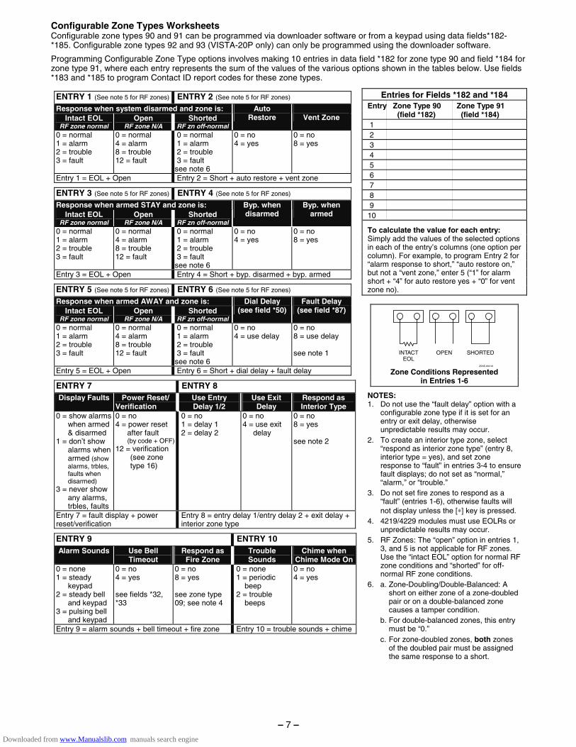
Configurable Zone Types Worksheets Configurable zone types 90 and 91 can be programmed via downloader software or from a keypad using data fields*182-*185. Configurable zone types 92 and 93 (VISTA-20P only) can only be programmed using the downloader software.
Programming Configurable Zone Type options involves making 10 entries in data field *182 for zone type 90 and field *184 for zone type 91, where each entry represents the sum of the values of the various options shown in the tables below. Use fields *183 and *185 to program Contact ID report codes for these zone types.
ENTRY 1 (See note 5 for RF zones) ENTRY 2 (See note 5 for RF zones) Response when system disarmed and zone is:
Intact EOL RF zone normal
Open RF zone N/A
Shorted RF zn off-normal
Auto Restore
Vent Zone
0 = normal 1 = alarm 2 = trouble 3 = fault
0 = normal 4 = alarm 8 = trouble 12 = fault
0 = normal 1 = alarm 2 = trouble 3 = fault see note 6
0 = no 4 = yes
0 = no 8 = yes
Entry 1 = EOL + Open Entry 2 = Short + auto restore + vent zone
ENTRY 3 (See note 5 for RF zones) ENTRY 4 (See note 5 for RF zones) Response when armed STAY and zone is:
Intact EOL RF zone normal
Open RF zone N/A
Shorted RF zn off-normal
Byp. when disarmed
Byp. when armed
0 = normal 1 = alarm 2 = trouble 3 = fault
0 = normal 4 = alarm 8 = trouble 12 = fault
0 = normal 1 = alarm 2 = trouble 3 = fault see note 6
0 = no 4 = yes
0 = no 8 = yes
Entry 3 = EOL + Open Entry 4 = Short + byp. disarmed + byp. armed
ENTRY 5 (See note 5 for RF zones) ENTRY 6 (See note 5 for RF zones) Response when armed AWAY and zone is:
Intact EOL RF zone normal
Open RF zone N/A
Shorted RF zn off-normal
Dial Delay (see field *50)
Fault Delay (see field *87)
0 = normal 1 = alarm 2 = trouble 3 = fault
0 = normal 4 = alarm 8 = trouble 12 = fault
0 = normal 1 = alarm 2 = trouble 3 = fault see note 6
0 = no 4 = use delay
0 = no 8 = use delay see note 1
Entry 5 = EOL + Open Entry 6 = Short + dial delay + fault delay
ENTRY 7 ENTRY 8 Display Faults Power Reset/
Verification Use Entry Delay 1/2
Use Exit Delay
Respond as Interior Type
0 = show alarms when armed & disarmed
1 = don’t show alarms when armed (show alarms, trbles, faults when disarmed)
3 = never show any alarms, trbles, faults
0 = no 4 = power reset
after fault (by code + OFF)
12 = verification (see zone
type 16)
0 = no 1 = delay 1 2 = delay 2
0 = no 4 = use exit
delay
0 = no 8 = yes see note 2
Entry 7 = fault display + power reset/verification
Entry 8 = entry delay 1/entry delay 2 + exit delay + interior zone type
ENTRY 9 ENTRY 10 Alarm Sounds Use Bell
Timeout Respond as
Fire Zone Trouble Sounds
Chime when Chime Mode On
0 = none 1 = steady
keypad 2 = steady bell
and keypad 3 = pulsing bell
and keypad
0 = no 4 = yes see fields *32, *33
0 = no 8 = yes see zone type 09; see note 4
0 = none 1 = periodic
beep 2 = trouble
beeps
0 = no 4 = yes
Entry 9 = alarm sounds + bell timeout + fire zone Entry 10 = trouble sounds + chime
Entries for Fields *182 and *184 Entry Zone Type 90 Zone Type 91 (field *182) (field *184) 1 2 3 4 5 6 7 8 9 10
To calculate the value for each entry: Simply add the values of the selected options in each of the entry’s columns (one option per column). For example, to program Entry 2 for “alarm response to short,” “auto restore on,” but not a “vent zone,” enter 5 (“1” for alarm short + “4” for auto restore yes + “0” for vent zone no).
OPEN SHORTEDINTACTEOL
ZONE-003-V0 Zone Conditions Represented
in Entries 1-6
NOTES: 1. Do not use the “fault delay” option with a
configurable zone type if it is set for an entry or exit delay, otherwise unpredictable results may occur.
2. To create an interior type zone, select “respond as interior zone type” (entry 8, interior type = yes), and set zone response to “fault” in entries 3-4 to ensure fault displays; do not set as “normal,” “alarm,” or “trouble.”
3. Do not set fire zones to respond as a “fault” (entries 1-6), otherwise faults will not display unless the [∗] key is pressed.
4. 4219/4229 modules must use EOLRs or unpredictable results may occur.
5. RF Zones: The “open” option in entries 1, 3, and 5 is not applicable for RF zones. Use the “intact EOL” option for normal RF zone conditions and “shorted” for off-normal RF zone conditions.
6. a. Zone-Doubling/Double-Balanced: A short on either zone of a zone-doubled pair or on a double-balanced zone causes a tamper condition.
b. For double-balanced zones, this entry must be “0.”
c. For zone-doubled zones, both zones of the doubled pair must be assigned the same response to a short.
– 7 –
Downloaded from www.Manualslib.com manuals search engine
*56 Zone Programming Menu Mode (press *56 while in Program mode) The Zone Programming Worksheet is on page 13. For each of the following prompts, make the desired entry, followed by the [∗] key to accept the entry. Refer to the Installation and Setup Guide for detailed explanations for each prompt.
SET TO CONFIRM? 0 = no; 1 = yes (See XMIT TO CONFIRM prompt later in this section.) We recommend that you confirm the programming of every transmitter.
ENTER ZN NUM. 01-64, 91, 92, 95, 96, 99 To quit, enter 00 to quit (returns to data field mode).
SUMMARY SCREEN: System displays a summary of the entered zone’s current programming. Press [∗] to continue.
ZONE TYPE 00 = Not used 07 = 24-Hr Audible 20 = Arm–STAY* 01 = Entry/exit #1 08 = 24-Hr Aux 21 = Arm–AWAY* 02 = Entry/exit #2 09 = Fire 22 = Disarm* 03 = Perimeter 10 = Interior w/Delay 23 = No Alarm Resp 04 = Interior Follower 12 = Monitor Zone 24 = Silent Burglary 05 = Trouble Day/Alarm Night 14 = Carbon Monoxide 77 = Keyswitch 06 = 24-Hr Silent 16 = Fire w/Verify 81 = AAV Monitor Zone *5800 button-type transmitters only 90-91 = Configurable
PARTITION 1, 2, or 3-common (VISTA-20P)
REPORT CODE 1-9, #+10 for 0, #+11 for B, #+12 for C, #+13 for D, #+14 for E, #+15 for F For Contact ID®, enter any non-zero entry as the first digit to enable reporting for this zone. To disable the report code for this zone, enter 00.
HARDWIRE TYPE Appears only for zones 02-08. Zone 1 is automatically set for EOL operation. Enter the desired hardwire type: 0 = EOL; 1 = NC; 2 = NO; 3 = zone doubling (ZD)†; 4 = double-balanced (DB)† († VISTA-20P)
RESPONSE TIME For hardwired zones 01-08. Enter the desired response time for this zone: 0 = 10mSec; 1 = 350mSec; 2 = 700mSec; 3 = 1.2 secs (see field ∗174). NOTE: If zone doubling is being used, the response time selected for zones 02-08 automatically applies to each zone’s associated doubled zone.
INPUT TYPE Skipped for zones 2-8, and for zones 10-16 if zone-doubling enabled. Enter the input type: 2 = AW (Aux wired zone); 3 = RF (supervised RF); 4 = UR (unsupervised RF); 5 = BR (unsupervised button type) NOTE: To change the input type of a previously programmed wireless device to a wired zone, you must first delete the transmitter’s serial number.
INPUT S/N Enroll the transmitter’s serial number and loop number as follows: 1. a. Transmit two open/close sequences (for button-type transmitters,
press and release the button twice, waiting about 4 seconds before pressing the button the second time).
OR b. Manually enter the 7-digit serial number printed on the label of the
transmitter. Press the [∗] key to move to the “L” position, then enter the loop number.
Use the [A] (Advance) and [B] (Back) keys to move the cursor forward and back within the screen. Pressing the [C] (Copy) key will insert the previously enrolled serial number, if desired (used when programming a transmitter with several input loops). To delete an existing serial number, enter 0 in the loop number field. The serial number will change to 0's. If 0 was entered in error, simply re-enter the loop number or press [#], and the serial number will return to the display.
2. Press [∗] to continue. The system now checks for a duplicate serial/loop number.
If no duplicate is found, the display shows the serial number and loop number.
3. Press [∗] to continue to confirmation screen. (prompts continued in next column)
XMIT TO confirm Appears if you answered “Yes” at the “Set to Confirm” prompt. Activate the loop input or button that corresponds to this zone. Press [∗] to continue. If the serial/loop number transmitted does not match the serial number entered, a display showing the entered and the received serial/loop numbers appears. If so, activate the loop input or button on the transmitter once again. If a match is not obtained, press the [#] key twice and then enter (or transmit) the correct serial number. Press [∗] to continue If the serial number transmitted matches the serial number entered, the keypad will beep 3 times and a summary display will appear, showing that zone's programming. An “s” indicates that a transmitter’s serial number has been enrolled.
Press [∗] to accept the zone information and continue.
PROGRAM ALPHA? Press 1 if you want to program descriptors for the zone now, and refer to the *82 Descriptor Programming section for procedure. To program descriptors later, enter 0 (no). Press [∗] to return to the ENTER ZN NUM prompt.
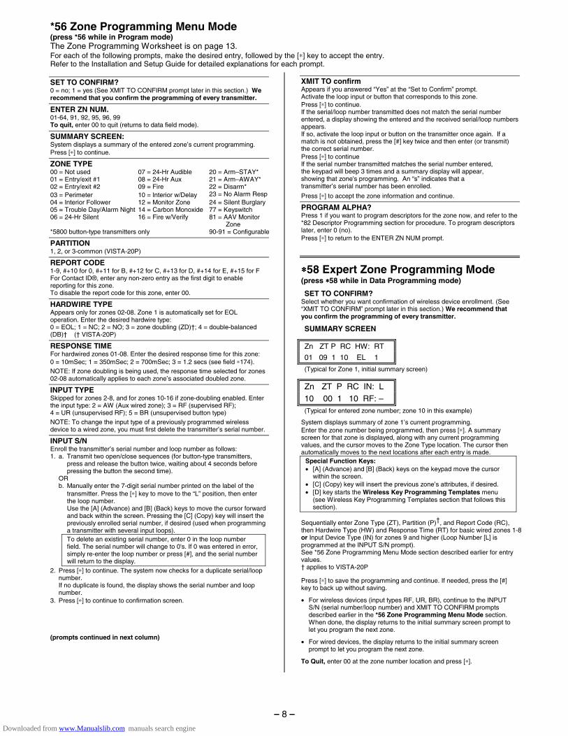
∗∗∗∗58 Expert Zone Programming Mode (press ∗∗∗∗58 while in Data Programming mode)
SET TO CONFIRM? Select whether you want confirmation of wireless device enrollment. (See “XMIT TO CONFIRM” prompt later in this section.) We recommend that you confirm the programming of every transmitter.
SUMMARY SCREEN
Zn ZT P RC HW: RT
01 09 1 10 EL 1 (Typical for Zone 1, initial summary screen)
Zn ZT P RC IN: L 10 00 1 10 RF: – (Typical for entered zone number; zone 10 in this example)
System displays summary of zone 1’s current programming. Enter the zone number being programmed, then press [∗]. A summary screen for that zone is displayed, along with any current programming values, and the cursor moves to the Zone Type location. The cursor then automatically moves to the next locations after each entry is made.
Special Function Keys: • [A] (Advance) and [B] (Back) keys on the keypad move the cursor
within the screen. • [C] (Copy) key will insert the previous zone’s attributes, if desired. • [D] key starts the Wireless Key Programming Templates menu
(see Wireless Key Programming Templates section that follows this section).
Sequentially enter Zone Type (ZT), Partition (P)†, and Report Code (RC), then Hardwire Type (HW) and Response Time (RT) for basic wired zones 1-8 or Input Device Type (IN) for zones 9 and higher (Loop Number [L] is programmed at the INPUT S/N prompt). See *56 Zone Programming Menu Mode section described earlier for entry values. † applies to VISTA-20P
Press [∗] to save the programming and continue. If needed, press the [#] key to back up without saving.
• For wireless devices (input types RF, UR, BR), continue to the INPUT S/N (serial number/loop number) and XMIT TO CONFIRM prompts described earlier in the *56 Zone Programming Menu Mode section. When done, the display returns to the initial summary screen prompt to let you program the next zone.
• For wired devices, the display returns to the initial summary screen prompt to let you program the next zone.
To Quit, enter 00 at the zone number location and press [∗].
– 8 –
Downloaded from www.Manualslib.com manuals search engine
Wireless Key Programming Templates (press the [D] key from *58 Menu mode Summary Screen) This procedure programs the wireless keys, but a key is not active for arming/disarming until it is assigned to a user number (see System Operation section, Assigning Attributes Command in the Installation Instructions).
TEMPLATE ? Enter desired template number 1–6 (see chart below), then press [∗] to continue. To exit the Template screen, press [#]. The system returns to the *58 Menu mode Summary Screen.
TEMPLATE SUMMARY
L 01 02 03 04 T 23 22 21 23
The selected template is displayed. The top line represents loop numbers, the bottom line represents each loop’s zone type. Press [∗] to accept template and continue.
PARTITION (VISTA-20P) Enter the partition (1, 2, or 3-common) in which the key is to be active. Press [∗] to continue.
ENTER START ZONE The system displays the lowest zone number of the highest available consecutive 4-zone group. To start at a different zone number, enter the zone desired, and press [∗]. If the system has four consecutive zones beginning with that zone, the zone number is displayed. If not, the system will again display a suggested zone that can be used. If the required number of consecutive zones is not available at all, the system will display “00”.
Press [∗] to accept.
Continue to the INPUT S/N (serial number/loop number) and XMIT TO CONFIRM prompts described earlier in the *56 Menu Mode section.
IMPORTANT: When confirmed, the key is not active for arming/disarming until it is assigned to a user number (using the assigning attributes command, attribute “4”). See System Operation section in Installation Instructions.
When done, the keypad beeps three times and the display returns to the ENTER START ZONE prompt to let you enter the starting zone for the next wireless key.
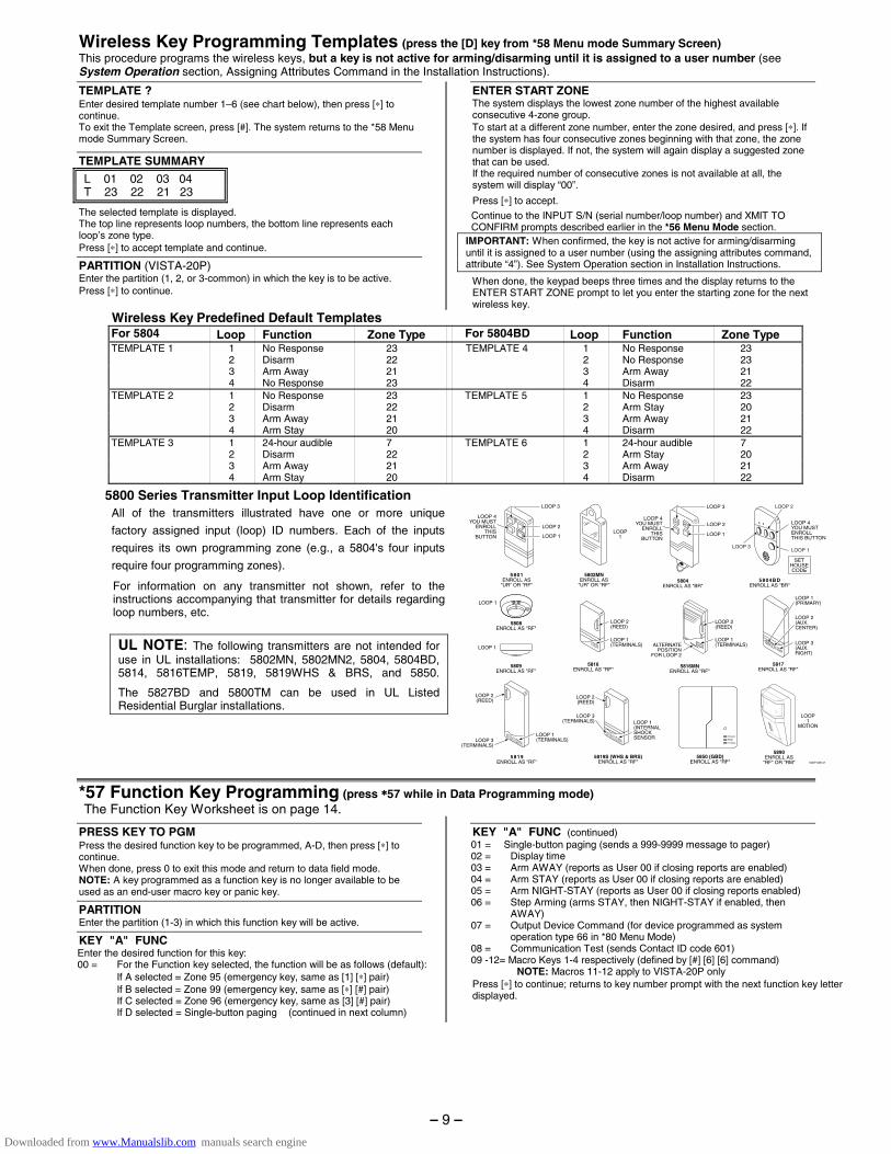
Wireless Key Predefined Default Templates For 5804 Loop Function Zone Type For 5804BD Loop Function Zone Type TEMPLATE 1 1 No Response 23 TEMPLATE 4 1 No Response 23 2 Disarm 22 2 No Response 23 3 Arm Away 21 3 Arm Away 21 4 No Response 23 4 Disarm 22 TEMPLATE 2 1 No Response 23 TEMPLATE 5 1 No Response 23 2 Disarm 22 2 Arm Stay 20 3 Arm Away 21 3 Arm Away 21 4 Arm Stay 20 4 Disarm 22 TEMPLATE 3 1 24-hour audible 7 TEMPLATE 6 1 24-hour audible 7 2 Disarm 22 2 Arm Stay 20 3 Arm Away 21 3 Arm Away 21 4 Arm Stay 20 4 Disarm 22
5800 Series Transmitter Input Loop Identification All of the transmitters illustrated have one or more unique
factory assigned input (loop) ID numbers. Each of the inputs
requires its own programming zone (e.g., a 5804's four inputs
require four programming zones).
For information on any transmitter not shown, refer to the instructions accompanying that transmitter for details regarding loop numbers, etc.
UL NOTE: The following transmitters are not intended for use in UL installations: 5802MN, 5802MN2, 5804, 5804BD, 5814, 5816TEMP, 5819, 5819WHS & BRS, and 5850.
The 5827BD and 5800TM can be used in UL Listed Residential Burglar installations.
5802MNENROLL AS
"UR" OR "RF"
LOOP1
V20P-006-V0
5817ENROLL AS "RF"
5890ENROLL AS
"RF" OR "RM"
LOOP 1
5808ENROLL AS "RF"
LOOP 1
5809ENROLL AS "RF"
5850 (GBD)ENROLL AS "RF"
(Green)
(Red)
(Yellow)
5804BDENROLL AS "BR"
LOOP 4YOU MUSTENROLLTHIS BUTTON
SETHOUSECODE
LOOP 3LOOP 1
LOOP 2
5804ENROLL AS "BR"
ON
5816MNENROLL AS "RF"
LOOP 2(REED)
5816ENROLL AS "RF"
LOOP 1(TERMINALS)
LOOP 2(REED)
LOOP 3(TERMINALS)
5819S (WHS & BRS)ENROLL AS "RF"
LOOP 1(INTERNALSHOCKSENSOR
LOOP 2(REED)
5819ENROLL AS "RF"
LOOP 2(REED)
LOOP 3(TERMINALS)
LOOP 1(TERMINALS)
5801ENROLL AS
"UR" OR "RF"
LOOP 3
LOOP 1
LOOP 2
LOOP 4YOU MUST
ENROLLTHIS
BUTTON LOOP 1
LOOP 2LOOP 4
YOU MUSTENROLL
THISBUTTON
LOOP 3
LOOP1
MOTION
LOOP 2(AUX.CENTER)
LOOP 1(PRIMARY)
LOOP 3(AUX.RIGHT)
LOOP 1(TERMINALS)ALTERNATE
POSITIONFOR LOOP 2
OFF
*57 Function Key Programming (press ∗∗∗∗57 while in Data Programming mode) The Function Key Worksheet is on page 14.
PRESS KEY TO PGM Press the desired function key to be programmed, A-D, then press [∗] to continue. When done, press 0 to exit this mode and return to data field mode. NOTE: A key programmed as a function key is no longer available to be used as an end-user macro key or panic key.
PARTITION Enter the partition (1-3) in which this function key will be active.
KEY "A" FUNC Enter the desired function for this key: 00 = For the Function key selected, the function will be as follows (default): If A selected = Zone 95 (emergency key, same as [1] [∗] pair) If B selected = Zone 99 (emergency key, same as [∗] [#] pair) If C selected = Zone 96 (emergency key, same as [3] [#] pair) If D selected = Single-button paging (continued in next column)
KEY "A" FUNC (continued) 01 = Single-button paging (sends a 999-9999 message to pager) 02 = Display time 03 = Arm AWAY (reports as User 00 if closing reports are enabled) 04 = Arm STAY (reports as User 00 if closing reports are enabled) 05 = Arm NIGHT-STAY (reports as User 00 if closing reports enabled) 06 = Step Arming (arms STAY, then NIGHT-STAY if enabled, then
AWAY) 07 = Output Device Command (for device programmed as system
operation type 66 in *80 Menu Mode) 08 = Communication Test (sends Contact ID code 601) 09 -12= Macro Keys 1-4 respectively (defined by [#] [6] [6] command) NOTE: Macros 11-12 apply to VISTA-20P only Press [∗] to continue; returns to key number prompt with the next function key letter displayed.
– 9 –
Downloaded from www.Manualslib.com manuals search engine
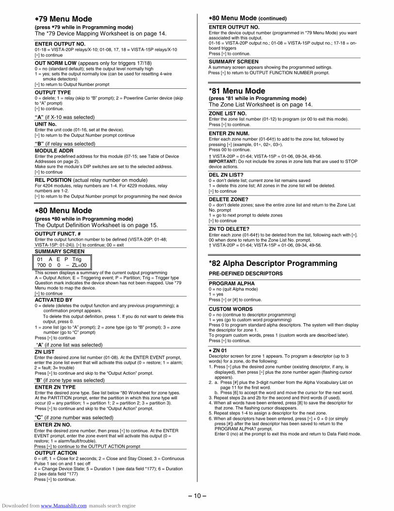
∗∗∗∗79 Menu Mode (press ∗∗∗∗79 while in Programming mode) The *79 Device Mapping Worksheet is on page 14.
ENTER OUTPUT NO. 01-18 = VISTA-20P relays/X-10; 01-08, 17, 18 = VISTA-15P relays/X-10 [∗] to continue
OUT NORM LOW (appears only for triggers 17/18) 0 = no (standard default); sets the output level normally high 1 = yes; sets the output normally low (can be used for resetting 4-wire
smoke detectors) [∗] to return to Output Number prompt
OUTPUT TYPE 0 = delete; 1 = relay (skip to “B” prompt); 2 = Powerline Carrier device (skip to “A” prompt) [∗] to continue.
“A” (if X-10 was selected) UNIT No. Enter the unit code (01-16, set at the device). [∗] to return to the Output Number prompt continue
“B” (if relay was selected) MODULE ADDR Enter the predefined address for this module (07-15; see Table of Device Addresses on page 2). Make sure the module’s DIP switches are set to the selected address. [∗] to continue
REL POSITION (actual relay number on module) For 4204 modules, relay numbers are 1-4. For 4229 modules, relay numbers are 1-2. [∗] to return to the Output Number prompt for programming the next device
∗∗∗∗80 Menu Mode (press ∗∗∗∗80 while in Programming mode) The Output Definition Worksheet is on page 15.
OUTPUT FUNCT. # Enter the output function number to be defined (VISTA-20P: 01-48; VISTA-15P: 01-24)). [∗] to continue; 00 = exit
SUMMARY SCREEN
01 A E P Trig ?00 0 0 – ZL=00
This screen displays a summary of the current output programming A = Output Action; E = Triggering event; P = Partition; Trig = Trigger type Question mark indicates the device shown has not been mapped. Use *79 Menu mode to map the device. [∗] to continue
ACTIVATED BY 0 = delete (deletes the output function and any previous programming); a
confirmation prompt appears. To delete this output definition, press 1. If you do not want to delete this output, press 0.
1 = zone list (go to “A” prompt); 2 = zone type (go to “B” prompt); 3 = zone number (go to “C” prompt)
Press [∗] to continue
“A” (if zone list was selected)
ZN LIST Enter the desired zone list number (01-08). At the ENTER EVENT prompt, enter the zone list event that will activate this output (0 = restore; 1 = alarm; 2 = fault; 3= trouble) Press [∗] to continue and skip to the “Output Action” prompt.
“B” (if zone type was selected)
ENTER ZN TYPE Enter the desired zone type. See list below *80 Worksheet for zone types. At the PARTITION prompt, enter the partition in which this zone type will occur (0 = any partition; 1 = partition 1; 2 = partition 2; 3 = partition 3). Press [∗] to continue and skip to the “Output Action” prompt.
“C” (if zone number was selected)
ENTER ZN NO. Enter the desired zone number, then press [∗] to continue. At the ENTER EVENT prompt, enter the zone event that will activate this output (0 = restore; 1 = alarm/fault/trouble). Press [∗] to continue to the OUTPUT ACTION prompt
OUTPUT ACTION 0 = off; 1 = Close for 2 seconds; 2 = Close and Stay Closed; 3 = Continuous Pulse 1 sec on and 1 sec off 4 = Change Device State; 5 = Duration 1 (see data field *177); 6 = Duration 2 (see data field *177) Press [∗] to continue.
∗∗∗∗80 Menu Mode (continued)
ENTER OUTPUT NO. Enter the device output number (programmed in *79 Menu Mode) you want associated with this output. 01-16 = VISTA-20P output no.; 01-08 = VISTA-15P output no.; 17-18 = on-board triggers Press [∗] to continue.
SUMMARY SCREEN A summary screen appears showing the programmed settings. Press [∗] to return to OUTPUT FUNCTION NUMBER prompt.
*81 Menu Mode (press *81 while in Programming mode) The Zone List Worksheet is on page 14.
ZONE LIST NO. Enter the zone list number (01-12) to program (or 00 to exit this mode). Press [∗] to continue.
ENTER ZN NUM. Enter each zone number (01-64†) to add to the zone list, followed by pressing [∗] (example, 01∗, 02∗, 03∗). Press 00 to continue.
† VISTA-20P = 01-64; VISTA-15P = 01-06, 09-34, 49-56. IMPORTANT: Do not include fire zones in zone lists that are used to STOP device actions.
DEL ZN LIST? 0 = don’t delete list; current zone list remains saved 1 = delete this zone list; All zones in the zone list will be deleted. [∗] to continue
DELETE ZONE? 0 = don’t delete zones; save the entire zone list and return to the Zone List No. prompt 1 = go to next prompt to delete zones [∗] to continue
ZN TO DELETE? Enter each zone (01-64†) to be deleted from the list, following each with [∗]. 00 when done to return to the Zone List No. prompt. † VISTA-20P = 01-64; VISTA-15P = 01-06, 09-34, 49-56.
*82 Alpha Descriptor Programming
PRE-DEFINED DESCRIPTORS
PROGRAM ALPHA 0 = no (quit Alpha mode) 1 = yes Press [∗] or [#] to continue.
CUSTOM WORDS 0 = no (continue to descriptor programming) 1 = yes (go to custom word programming) Press 0 to program standard alpha descriptors. The system will then display the descriptor for zone 1. To program custom words, press 1 (custom words are described later). Press [∗] to continue.
∗∗∗∗ ZN 01 Descriptor screen for zone 1 appears. To program a descriptor (up to 3 words) for a zone, do the following: 1. Press [∗] plus the desired zone number (existing descriptor, if any, is
displayed), then press [∗] plus the zone number again (flashing cursor appears).
2. a. Press [#] plus the 3-digit number from the Alpha Vocabulary List on page 11 for the first word.
b. Press [6] to accept the word and move the cursor for the next word. 3. Repeat steps 2a and 2b for the second and third words (if used). 4. When all words have been entered, press [8] to save the descriptor for
that zone. The flashing cursor disappears. 5. Repeat steps 1-4 to assign a descriptor for the next zone. 6. When all descriptors have been entered, press [∗] + 0 + 0 (or simply
press [#]) after the last descriptor has been saved to return to the PROGRAM ALPHA? prompt.
Enter 0 (no) at the prompt to exit this mode and return to Data Field mode.
– 10 –
Downloaded from www.Manualslib.com manuals search engine
*82 Alpha Descriptor Programming (continued)
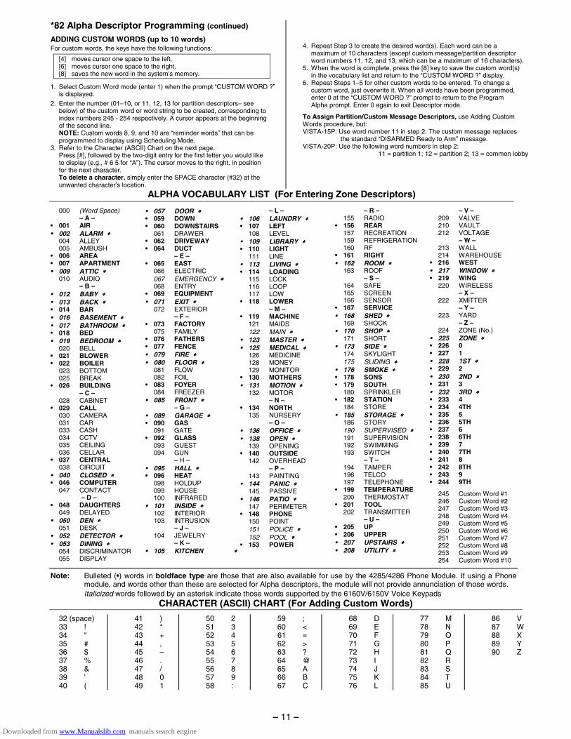
ADDING CUSTOM WORDS (up to 10 words) For custom words, the keys have the following functions:
[4] moves cursor one space to the left. [6] moves cursor one space to the right. [8] saves the new word in the system's memory.
1. Select Custom Word mode (enter 1) when the prompt “CUSTOM WORD ?” is displayed.
2. Enter the number (01–10, or 11, 12, 13 for partition descriptors– see below) of the custom word or word string to be created, corresponding to index numbers 245 - 254 respectively. A cursor appears at the beginning of the second line.
NOTE: Custom words 8, 9, and 10 are “reminder words” that can be programmed to display using Scheduling Mode.
3. Refer to the Character (ASCII) Chart on the next page. Press [#], followed by the two-digit entry for the first letter you would like
to display (e.g., # 6 5 for “A”). The cursor moves to the right, in position for the next character.
To delete a character, simply enter the SPACE character (#32) at the unwanted character’s location.
4. Repeat Step 3 to create the desired word(s). Each word can be a
maximum of 10 characters (except custom message/partition descriptor word numbers 11, 12, and 13, which can be a maximum of 16 characters).
5. When the word is complete, press the [8] key to save the custom word(s) in the vocabulary list and return to the “CUSTOM WORD ?” display.
6. Repeat Steps 1–5 for other custom words to be entered. To change a custom word, just overwrite it. When all words have been programmed, enter 0 at the “CUSTOM WORD ?” prompt to return to the Program Alpha prompt. Enter 0 again to exit Descriptor mode.
To Assign Partition/Custom Message Descriptors, use Adding Custom Words procedure, but: VISTA-15P: Use word number 11 in step 2. The custom message replaces
the standard “DISARMED Ready to Arm” message. VISTA-20P: Use the following word numbers in step 2: 11 = partition 1; 12 = partition 2; 13 = common lobby
ALPHA VOCABULARY LIST (For Entering Zone Descriptors)
000 (Word Space) – A – • 001 AIR • 002 ALARM ∗∗∗∗ 004 ALLEY 005 AMBUSH • 006 AREA • 007 APARTMENT • 009 ATTIC ∗∗∗∗ 010 AUDIO – B – • 012 BABY ∗∗∗∗ • 013 BACK ∗∗∗∗ • 014 BAR • 016 BASEMENT ∗∗∗∗ • 017 BATHROOM ∗∗∗∗ • 018 BED • 019 BEDROOM ∗∗∗∗ 020 BELL • 021 BLOWER • 022 BOILER 023 BOTTOM 025 BREAK • 026 BUILDING – C – 028 CABINET • 029 CALL 030 CAMERA 031 CAR 033 CASH 034 CCTV 035 CEILING 036 CELLAR • 037 CENTRAL 038 CIRCUIT • 040 CLOSED ∗∗∗∗ • 046 COMPUTER 047 CONTACT – D – • 048 DAUGHTERS 049 DELAYED • 050 DEN ∗∗∗∗ 051 DESK • 052 DETECTOR ∗∗∗∗ • 053 DINING ∗∗∗∗ 054 DISCRIMINATOR 055 DISPLAY
• 057 DOOR ∗∗∗∗ • 059 DOWN • 060 DOWNSTAIRS 061 DRAWER • 062 DRIVEWAY • 064 DUCT – E – • 065 EAST 066 ELECTRIC 067 EMERGENCY ∗∗∗∗ 068 ENTRY • 069 EQUIPMENT • 071 EXIT ∗∗∗∗ 072 EXTERIOR – F – • 073 FACTORY 075 FAMILY • 076 FATHERS • 077 FENCE • 079 FIRE ∗∗∗∗ • 080 FLOOR ∗∗∗∗ 081 FLOW 082 FOIL • 083 FOYER 084 FREEZER • 085 FRONT ∗∗∗∗ – G – • 089 GARAGE ∗∗∗∗ • 090 GAS 091 GATE • 092 GLASS 093 GUEST 094 GUN – H – • 095 HALL ∗∗∗∗ • 096 HEAT 098 HOLDUP 099 HOUSE 100 INFRARED • 101 INSIDE ∗∗∗∗ 102 INTERIOR 103 INTRUSION – J – 104 JEWELRY – K – • 105 KITCHEN ∗∗∗∗
– L – • 106 LAUNDRY ∗∗∗∗ • 107 LEFT 108 LEVEL • 109 LIBRARY ∗∗∗∗ • 110 LIGHT 111 LINE • 113 LIVING ∗∗∗∗ • 114 LOADING 115 LOCK 116 LOOP 117 LOW • 118 LOWER – M – • 119 MACHINE 121 MAIDS 122 MAIN ∗∗∗∗ • 123 MASTER ∗∗∗∗ • 125 MEDICAL ∗∗∗∗ 126 MEDICINE 128 MONEY 129 MONITOR • 130 MOTHERS • 131 MOTION ∗∗∗∗ 132 MOTOR – N – • 134 NORTH 135 NURSERY – O – • 136 OFFICE ∗∗∗∗ • 138 OPEN ∗∗∗∗ 139 OPENING • 140 OUTSIDE 142 OVERHEAD – P – 143 PAINTING • 144 PANIC ∗∗∗∗ 145 PASSIVE • 146 PATIO ∗∗∗∗ 147 PERIMETER • 148 PHONE 150 POINT 151 POLICE ∗∗∗∗ 152 POOL ∗∗∗∗ • 153 POWER
– R – 155 RADIO • 156 REAR 157 RECREATION 159 REFRIGERATION 160 RF • 161 RIGHT • 162 ROOM ∗∗∗∗ 163 ROOF – S – 164 SAFE 165 SCREEN 166 SENSOR • 167 SERVICE • 168 SHED ∗∗∗∗ 169 SHOCK • 170 SHOP ∗∗∗∗ 171 SHORT • 173 SIDE ∗∗∗∗ 174 SKYLIGHT 175 SLIDING ∗∗∗∗ • 176 SMOKE ∗∗∗∗ • 178 SONS • 179 SOUTH 180 SPRINKLER • 182 STATION 184 STORE • 185 STORAGE ∗∗∗∗ 186 STORY 190 SUPERVISED ∗∗∗∗ 191 SUPERVISION 192 SWIMMING 193 SWITCH – T – 194 TAMPER 196 TELCO 197 TELEPHONE • 199 TEMPERATURE 200 THERMOSTAT • 201 TOOL 202 TRANSMITTER – U – • 205 UP • 206 UPPER • 207 UPSTAIRS ∗∗∗∗ • 208 UTILITY ∗∗∗∗
– V – 209 VALVE 210 VAULT 212 VOLTAGE – W – 213 WALL 214 WAREHOUSE • 216 WEST • 217 WINDOW ∗∗∗∗ • 219 WING 220 WIRELESS – X – 222 XMITTER – Y – 223 YARD – Z – 224 ZONE (No.) • 225 ZONE ∗∗∗∗ • 226 0 • 227 1 • 228 1ST ∗∗∗∗ • 229 2 • 230 2ND ∗∗∗∗ • 231 3 • 232 3RD ∗∗∗∗ • 233 4 • 234 4TH • 235 5 • 236 5TH • 237 6 • 238 6TH • 239 7 • 240 7TH • 241 8 • 242 8TH • 243 9 • 244 9TH
245 Custom Word #1 246 Custom Word #2 247 Custom Word #3 248 Custom Word #4 249 Custom Word #5 250 Custom Word #6 251 Custom Word #7 252 Custom Word #8 253 Custom Word #9 254 Custom Word #10
Note: Bulleted (•) words in boldface type are those that are also available for use by the 4285/4286 Phone Module. If using a Phone module, and words other than these are selected for Alpha descriptors, the module will not provide annunciation of those words.
Italicized words followed by an asterisk indicate those words supported by the 6160V/6150V Voice Keypads CHARACTER (ASCII) CHART (For Adding Custom Words)
32 (space) 33 ! 34 " 35 # 36 $ 37 % 38 & 39 ' 40 (
41 ) 42 * 43 + 44 , 45 – 46 . 47 / 48 0 49 1
50 2 51 3 52 4 53 5 54 6 55 7 56 8 57 9 58 :
59 ; 60 < 61 = 62 > 63 ? 64 @ 65 A 66 B 67 C
68 D 69 E 70 F 71 G 72 H 73 I 74 J 75 K 76 L
77 M 78 N 79 O 80 P 81 Q 82 R 83 S 84 T 85 U
86 V 87 W 88 X 89 Y 90 Z
– 11 –
Downloaded from www.Manualslib.com manuals search engine
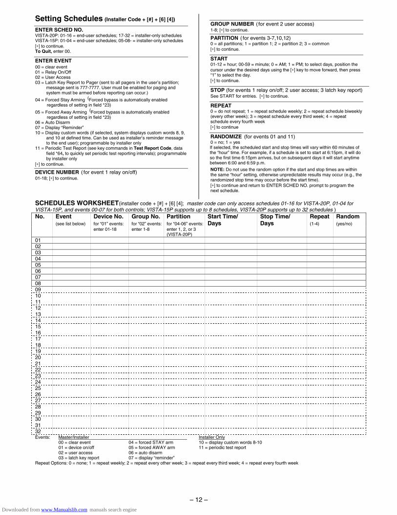
Setting Schedules (Installer Code + [#] + [6] [4])
ENTER SCHED NO. VISTA-20P: 01-16 = end-user schedules; 17-32 = installer-only schedules VISTA-15P: 01-04 = end-user schedules; 05-08- = installer-only schedules [∗] to continue. To Quit, enter 00.
ENTER EVENT 00 = clear event 01 = Relay On/Off 02 = User Access 03 = Latch Key Report to Pager (sent to all pagers in the user’s partition;
message sent is 777-7777. User must be enabled for paging and system must be armed before reporting can occur.)
04 = Forced Stay Arming (Forced bypass is automatically enabled regardless of setting in field *23)
05 = Forced Away Arming (Forced bypass is automatically enabled regardless of setting in field *23)
06 = Auto Disarm 07 = Display “Reminder” 10 = Display custom words (if selected, system displays custom words 8, 9,
and 10 at defined time. Can be used as installer’s reminder message to the end user); programmable by installer only
11 = Periodic Test Report (see key commands in Test Report Code, data field *64, to quickly set periodic test reporting intervals); programmable by installer only
[∗] to continue.
DEVICE NUMBER ( for event 1 relay on/off) 01-18; [∗] to continue.
GROUP NUMBER ( for event 2 user access) 1-8; [∗] to continue.
PARTITION ( for events 3-7,10,12) 0 = all partitions; 1 = partition 1; 2 = partition 2; 3 = common [∗] to continue.
START 01-12 = hour; 00-59 = minute; 0 = AM; 1 = PM; to select days, position the cursor under the desired days using the [∗] key to move forward, then press “1” to select the day. [∗] to continue.
STOP (for events 1 relay on/off; 2 user access; 3 latch key report) See START for entries. [∗] to continue.
REPEAT 0 = do not repeat; 1 = repeat schedule weekly; 2 = repeat schedule biweekly (every other week); 3 = repeat schedule every third week; 4 = repeat schedule every fourth week [∗] to continue
RANDOMIZE (for events 01 and 11) 0 = no; 1 = yes If selected, the scheduled start and stop times will vary within 60 minutes of the “hour” time. For example, if a schedule is set to start at 6:15pm, it will do so the first time 6:15pm arrives, but on subsequent days it will start anytime between 6:00 and 6:59 p.m.
NOTE: Do not use the random option if the start and stop times are within the same “hour” setting, otherwise unpredictable results may occur (e.g., the randomized stop time may occur before the start time). [∗] to continue and return to ENTER SCHED NO. prompt to program the next schedule.
SCHEDULES WORKSHEET(installer code + [#] + [6] [4]; master code can only access schedules 01-16 for VISTA-20P, 01-04 for VISTA-15P, and events 00-07 for both controls; VISTA-15P supports up to 8 schedules, VISTA-20P supports up to 32 schedules ) No. Event Device No. Group No. Partition Start Time/ Stop Time/ Repeat Random (see list below) for “01” events: for “02” events: for “04-06” events: Days Days (1-4) (yes/no) enter 01-18 enter 1-8 enter 1, 2, or 3 (VISTA-20P) 01 02 03 04 05 06 07 08 09 10 11 12 13 14 15 16 17 18 19 20 21 22 23 24 25 26 27 28 29 30 31 32 Events: Master/Installer Installer Only 00 = clear event 04 = forced STAY arm 10 = display custom words 8-10 01 = device on/off 05 = forced AWAY arm 11 = periodic test report 02 = user access 06 = auto disarm 03 = latch key report 07 = display “reminder” Repeat Options: 0 = none; 1 = repeat weekly; 2 = repeat every other week; 3 = repeat every third week; 4 = repeat every fourth week
– 12 –
Downloaded from www.Manualslib.com manuals search engine
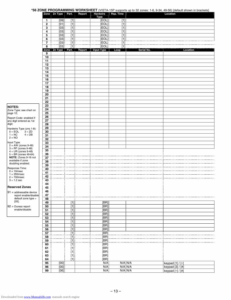
*56 ZONE PROGRAMMING WORKSHEET (VISTA-15P supports up to 32 zones: 1-6, 9-34, 49-56) [default shown in brackets] Zone Zn Type Part. Report Hardwire
Type Rsp. Time Location
1 [09] [1] [EOL] [1] 2 [01] [1] [EOL] [1] 3 [03] [1] [EOL] [1] 4 [03] [1] [EOL] [1] 5 [03] [1] [EOL] [1] 6 [03] [1] [EOL] [1] 7 [03] [1] [EOL] [1] 8 [03] [1] [EOL] [1]
Zone Zn Type Part. Report Input Type Loop Serial No. Location 9 10 11 12 13 14 15 16 17 18 19 20 21 22 23 24 25 26 27 28 29 30 31 32 33 34 35 36 37 38 39 40 41 42 43 44 45 46 47 48 49 [1] [BR] 50 [1] [BR] 51 [1] [BR] 52 [1] [BR] 53 [1] [BR] 54 [1] [BR] 55 [1] [BR] 56 [1] [BR] 57 [1] [BR] 58 [1] [BR] 59 [1] [BR] 60 [1] [BR] 61 [1] [BR] 62 [1] [BR] 63 [1] [BR] 64 [1] [BR] 95 [00] N/A N/A N/A keypad [1] / [∗] 96 [00] N/A N/A N/A keypad [3] / [#] 99 [06] N/A N/A N/A keypad [∗] / [#]
NOTES: Zone Type: see chart on page 12;
Report Code: enabled if any digit entered as 1st digit;
Hardwire Type (zns 1-8): 0 = EOL 3 = ZD 1 = NC 4 = DB 2 = NO
Input Type: 2 = AW (zones 9-48) 3 = RF (zones 9-48) 4 = UR (zones 9-48) 5 = BR (zones 49-64) NOTE: Zones 9-16 not available if zone doubling enabled.
Response Time: 0 = 10msec 1 = 350msec 2 = 700msec 3 = 1.2 sec
Reserved Zones
91 = addressable device report enable/disable
default zone type = [05].
92 = Duress report enable/disable
– 13 –
Downloaded from www.Manualslib.com manuals search engine
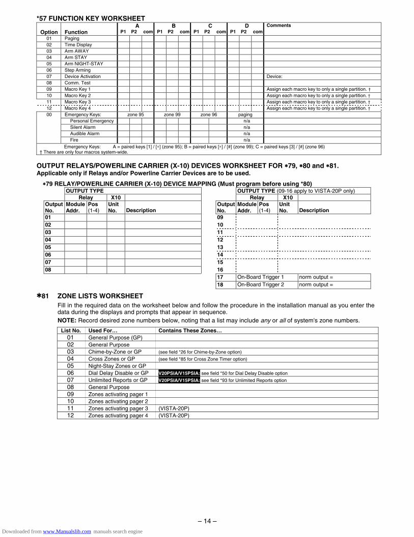
*57 FUNCTION KEY WORKSHEET
Option Function
A P1 P2 com
B P1 P2 com
C P1 P2 com
D P1 P2 com
Comments
01 Paging 02 Time Display 03 Arm AWAY 04 Arm STAY 05 Arm NIGHT-STAY 06 Step Arming 07 Device Activation Device: 08 Comm. Test 09 Macro Key 1 Assign each macro key to only a single partition. † 10 Macro Key 2 Assign each macro key to only a single partition. † 11 Macro Key 3 Assign each macro key to only a single partition. † 12 Macro Key 4 Assign each macro key to only a single partition. † 00 Emergency Keys: zone 95 zone 99 zone 96 paging Personal Emergency n/a Silent Alarm n/a Audible Alarm n/a Fire n/a
Emergency Keys: A = paired keys [1] / [∗] (zone 95); B = paired keys [∗] / [#] (zone 99); C = paired keys [3] / [#] (zone 96) † There are only four macros system-wide.
OUTPUT RELAYS/POWERLINE CARRIER (X-10) DEVICES WORKSHEET FOR ∗∗∗∗79, ∗∗∗∗80 and ∗∗∗∗81. Applicable only if Relays and/or Powerline Carrier Devices are to be used.
∗∗∗∗79 RELAY/POWERLINE CARRIER (X-10) DEVICE MAPPING (Must program before using *80) OUTPUT TYPE OUTPUT TYPE (09-16 apply to VISTA-20P only) Relay X10 Relay X10 Output No.
Module Addr.
Pos (1-4)
Unit No.
Description
OutputNo.
ModuleAddr.
Pos (1-4)
Unit No.
Description
01 09 02 10 03 11 04 12 05 13 06 14 07 15 08 16 17 On-Board Trigger 1 norm output = 18 On-Board Trigger 2 norm output =
✱81 ZONE LISTS WORKSHEET Fill in the required data on the worksheet below and follow the procedure in the installation manual as you enter the data during the displays and prompts that appear in sequence. NOTE: Record desired zone numbers below, noting that a list may include any or all of system's zone numbers.
List No. Used For… Contains These Zones… 01 General Purpose (GP) 02 General Purpose 03 Chime-by-Zone or GP (see field *26 for Chime-by-Zone option) 04 Cross Zones or GP (see field *85 for Cross Zone Timer option) 05 Night-Stay Zones or GP 06 Dial Delay Disable or GP V20PSIA/V15PSIA: see field *50 for Dial Delay Disable option 07 Unlimited Reports or GP V20PSIA/V15PSIA: see field *93 for Unlimited Reports option 08 General Purpose 09 Zones activating pager 1 10 Zones activating pager 2 11 Zones activating pager 3 (VISTA-20P) 12 Zones activating pager 4 (VISTA-20P)
– 14 –
Downloaded from www.Manualslib.com manuals search engine
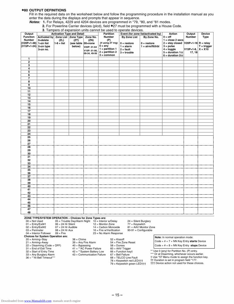
✱80 OUTPUT DEFINITIONS Fill in the required data on the worksheet below and follow the programming procedure in the installation manual as you
enter the data during the displays and prompts that appear in sequence. Notes: 1. For Relays, 4229 and 4204 devices are programmed in *79, *80, and *81 modes. 2. For Powerline Carrier devices (plcd), field ✱27 must be programmed with a House Code. 3. Tampers of expansion units cannot be used to operate devices.
Activation Type and Detail Event (for zone list/activated by)Output Function Number
(V20P=1-48) (V15P=1-24)
Activated by 0=delete 1=zn list 2=zn type 3=zn no.
Zone List (ZL)
1-8 = list
Zone Type (ZT)
(see table below)
Zone No. (ZN)
00=none
V20P: 01-64
V15P: 01-06, 09-34, 49-56
Partition Number
(P) (if using ZT trig)
0 = any 1 = partition 1 2 = partition 2 3 = common
By Zone List 0 = restore 1 = alarm 2 = fault 3 = trouble
By Zone No. 0 = restore 1 = alrm/flt/trbl
Action 0 = off 1 = close 2 secs 2 = stay closed 3 = pulse 4 = toggle 5 = duration 1†† 6 = duration 2††
Output Number
V20P=1-18 V15P=1-8, 17, 18
Device Type
R = relay T = trigger X = X10
1 2 3 4 5 6 7 8 9 10 11 12 13 14 15 16 17 18 19 20 21 22 23 24 25 26 27 28 29 30 31 32 33 34 35 36 37 38 39 40 41 42 43 44 45 46 47 48
ZONE TYPE/SYSTEM OPERATION – Choices for Zone Types are: 00 = Not Used 05 = Trouble Day/Alarm Night 10 = Interior w/Delay 24 = Silent Burglary 01 = Entry/Exit#1 06 = 24 Hr Silent 12 = Monitor Zone 77 = Keyswitch 02 = Entry/Exit#2 07 = 24 Hr Audible 14 = Carbon Monoxide 81 = AAV Monitor Zone 03 = Perimeter 08 = 24 Hr Aux 16 = Fire w/Verification 90-91 = Configurable 04 = Interior Follower 09 = Fire 23 = No Alarm Response
Choices for System Operation are: 20 = Arming–Stay 38 = Chime 52 = Kissoff 21 = Arming–Away 39 = Any Fire Alarm 54 = Fire Zone Reset 22 = Disarming (Code + OFF) 40 = Bypassing 58 = Duress 31 = End of Exit Time 41 = **AC Power Failure 60 = AAV Trigger 32 = Start of Entry Time 42 = **System Battery Low 66 = Function key† 33 = Any Burglary Alarm 43 = Communication Failure 67 = Bell Failure 36 = **At Bell Timeout*** 68 = TELCO Line Fault 78 = Keyswitch red LED††† 79 = Keyswitch green LED†††
Note: In normal operation mode:
Code + # + 7 + NN Key Entry starts Device
Code + # + 8 + NN Key Entry stops Device
** Use 0 (any) for Partition No. (P) entry. *** Or at Disarming, whichever occurs earlier. † Use *57 Menu mode to assign the function key. †† Duration is set in program field *177. ††† Device action not used for these choices.
– 15 –
Downloaded from www.Manualslib.com manuals search engine

CL
AS
S 2
PL
UG
-IN
TR
AN
SF
OR
ME
R16
.5V
AC
, 25V
A(e
.g. A
DE
MC
O N
o. 1
321)
.(U
SE
No.
132
1CN
IN C
AN
AD
A)
TO 1
10VA
C
UN
SW
ITC
HE
DO
UTL
ET
(24H
R)
�+
TH
IS E
QU
IPM
EN
T S
HO
ULD
BE
INS
TALL
ED
IN A
CC
OR
DA
NC
E W
ITH
TH
E N
AT
ION
AL
FIR
E P
RO
TE
CT
ION
AS
SO
CIA
TIO
N'S
STA
ND
AR
D 7
2,
CH
AP
TE
R 2
(N
AT
ION
AL
FIR
E P
RO
TE
CT
ION
AS
SO
CIA
TIO
N,
BA
TT
ER
Y-M
AR
CH
PA
RK
, Q
UIN
CY
,MA
02
26
9).
PR
INT
ED
IN
FO
RM
AT
ION
DE
SC
RIB
ING
PR
OP
ER
IN
STA
LL
AT
ION
,O
PE
RA
TIO
N,T
ES
TIN
G,
MA
INT
EN
AN
CE
,E
VA
CU
ATIO
N P
LA
NN
ING
AN
D R
EPA
IRS
ER
VIC
E I
S T
O B
E P
RO
VID
ED
WIT
H T
HIS
EQ
UIP
ME
NT.
24-H
R B
AT
TE
RY
STA
ND
BY
RE
QU
IRE
D F
OR
FIR
E IN
STA
LL
AT
ION
S. U
SE
12V
, 17.
2AH
BA
TT
ER
Y F
OR
600
mA
AU
X P
OW
ER
. SE
EIN
ST
RU
CT
ION
S.
BA
TT
ER
Y C
APA
CIT
Y F
OR
EM
ER
GE
NC
YB
UR
GL
AR
Y S
TAN
DB
Y U
SE
AT
LE
AS
T 4
HR
S
US
E U
L LI
ST
ED
LIM
ITE
D E
NE
RG
YC
AB
LE F
OR
ALL
CO
NN
EC
TIO
NS
US
E 1
361X
10 T
RA
NS
FO
RM
ER
IN
TE
RFA
CE
IN P
LAC
E O
F 1
321
OR
1321
CN
WH
EN
PO
WE
R L
INE
CA
RR
IER
DE
VIC
ES
AR
E B
EIN
G U
SE
D. (
SE
EIN
ST
RU
CT
ION
S F
OR
CO
NN
EC
TIO
NS
)
FO
R C
OM
PLE
TE
INF
OR
MAT
ION
, SE
EIN
ST
RU
CT
ION
S K
5305
-1V
2
ALA
RM
OU
TPU
T10
.5–1
3.8V
DC
, 2A
MA
X.
(600
mA
MA
X. F
OR
UL
US
AG
E, I
NC
LUD
ING
AU
X P
OW
ER
) S
TE
AD
YF
OR
BU
RG
LAR
Y/P
AN
IC,
TE
MP
OR
AL
PU
LSE
SO
UN
DIN
G F
OR
FIR
E.
CA
N U
SE
AD
EM
CO
No.
702
SIR
EN
, OR
12V
BE
LL).
SE
E IN
ST
RU
CT
ION
S.
CH
AR
GIN
G V
OLT
AG
E13
.8V
DC
. MA
XIM
UM
CH
AR
GIN
G C
UR
RE
NT
650m
A.
BA
TT
ER
Y12
V, 4
AH
� +
�+
BLA
CK
RE
D
SE
ALE
D L
EA
D-A
CID
TY
PE
.B
ATT
ER
Y N
OR
MA
LLY
NE
ED
NO
T B
ER
EP
LAC
ED
FO
R A
T L
EA
ST
3 Y
RS
.
TO D
ET
ER
MIN
E T
OTA
L S
TAN
DB
Y L
OA
DO
N B
ATT
ER
Y, A
DD
100
mA
TO
TO
TAL
OF
AU
X. P
OW
ER
OU
TP
UT
AN
D R
EM
OT
EK
EY
PAD
CU
RR
EN
TS
.
FLY
ING
LE
AD
SF
OR
BAT
TE
RY
CO
NN
EC
TIO
N
CO
NN
EC
TIO
N O
F T
HE
FIR
E A
LAR
MS
IGN
AL
TO A
FIR
E A
LAR
MH
EA
DQ
UA
RT
ER
S O
R A
CE
NT
RA
L S
TAT
ION
SH
ALL
BE
PE
RM
ITT
ED
ON
LY W
ITH
TH
EP
ER
MIS
SIO
N O
F T
HE
LO
CA
L A
UT
HO
RIT
YH
AV
ING
JU
RIS
DIC
TIO
N. T
HE
BU
RG
LAR
ALA
RM
SIG
NA
L S
HA
LL N
OT
BE
CO
NN
EC
TE
D T
O A
PO
LIC
E E
ME
RG
EN
CY
NU
MB
ER
.
OPTIONALFOR UP TO 40 ADDITIONAL ZONES
( FROM EITHER OR BOTH GROUPS)
BLK
RE
DG
RN
YE
L
12
37
811
1217
2021
2223
2425
EA
RT
H
GR
OU
ND
SE
E
INS
TR
UC
TIO
NS
FO
R P
RO
PE
RG
RO
UN
DIN
G
TE
LE
PH
ON
E W
IRIN
G(V
IA R
J31X
* JA
CK
AN
D D
IRE
CT
C
ON
NE
CT
CO
RD
) *C
A38
A IN
CA
NA
DA
DO
C L
OA
D N
O.:
3
BLACK: KEYPAD GROUND (- ) RETURN
RED: KEYPAD PWR ( + )
GREEN: DATA IN FROM KEYPAD
YELLOW: KEYPAD DATA OUT�
�
RE
MO
TE
KE
YPA
DS
AN
D O
TH
ER
AD
DR
ES
SA
BL
ED
EV
ICE
S(e
.g. 5
800T
M,
4285
/428
6, L
RR
,42
19, 4
229,
4204
, 588
1)
WA
RN
ING
:TO
PR
EV
EN
T R
ISK
OF
SH
OC
K,
DIS
CO
NN
EC
T T
EL
EP
HO
NE
LIN
E A
T T
EL
CO
JAC
K B
EF
OR
E S
ER
VIC
ING
TH
IS U
NIT
.
BLK
RE
DG
RN
YE
L
TO T
ER
M 4
TO T
ER
M 5
TO T
ER
M 6
TO T
ER
M 7
BLK
RE
DG
RN
YE
L
AN
D/O
R
RIN
G(G
RAY
)T
IP(G
RE
EN
)R
ING
(RE
D)
INC
OM
ING
PH
ON
E L
INE
HA
ND
SE
T
ZONE 1
ZONE 2
HI
LO
HI
LO
ZONE 3
ZONE 4
HI
LO
HI
LO
ZONE 5
ZONE 6
HI
LO
HI
LO
ZONE 7
ZONE 8
HI
LO
HI
LO
•
MA
XIM
UM
LO
OP
RE
SIS
TAN
CE
: (E
AC
H Z
ON
E)
300
OH
MS
(P
LUS
EO
LR)
• • R
ES
PO
NS
E, Z
ON
ES
1-8
: 10,
350
, OR
700
MS
EC
(P
RO
GR
AM
MA
BLE
)
8-P
IN C
ON
NE
CTO
RU
SE
D F
OR
136
1X10
TR
AN
SF
OR
ME
RC
ON
NE
CT
ION
S A
ND
FO
RO
N-B
OA
RD
TR
IGG
ER
SS
EE
INS
TR
UC
TIO
NS
.7
8(U
SE
SA
4120
XM
-1C
AB
LE)
TIP
(BR
OW
N)
}}
TH
IS D
EV
ICE
CO
MP
LIE
S W
ITH
PA
RT
15
OF
FC
C R
ULE
S.
OP
ER
ATIO
N IS
SU
BJE
CT
TO
TH
E F
OLL
OW
ING
TW
O
CO
ND
ITIO
NS
: (1)
TH
IS D
EV
ICE
MAY
NO
T C
AU
SE
HA
RM
FU
LIN
TE
RF
ER
EN
CE
, AN
D (
2) T
HIS
DE
VIC
E M
US
T A
CC
EP
T A
NY
INT
ER
FE
RE
NC
E R
EC
EIV
ED
, IN
CLU
DIN
G IN
TE
RF
ER
EN
CE
TH
AT M
AY C
AU
SE
UN
DE
SIR
ED
OP
ER
ATIO
N.
CO
MP
LIE
S W
ITH
FC
C R
ULE
S, P
AR
T 6
8.F
CC
RE
GIS
TR
ATIO
N N
O. 5
GB
US
A-4
4003
-AL-
ER
ING
ER
EQ
UIV
ALE
NC
E: 0
.1B
.
WE
EK
LY T
ES
TIN
G IS
RE
QU
IRE
D T
O E
NS
UR
E P
RO
PE
R O
PE
RA
TIO
N O
F T
HIS
SY
ST
EM
. IN
AD
DIT
ION
, TH
IS S
YS
TE
M M
US
T B
E C
HE
CK
ED
BY
A Q
UA
LIF
IED
TE
CH
NIC
IAN
AT
LE
AS
T O
NC
E E
VE
RY
TH
RE
E (
3) Y
EA
RS
.CAN BE USED FOR 2-WIRE SMOKE DETECTORS
RE
D J
UM
PE
RC
UT
FO
R B
ELL
SU
PE
RV
ISIO
N.
ALS
O, C
ON
NE
CT
200
0 O
HM
R
ES
ISTO
R D
IRE
CT
LY A
CR
OS
S
SO
UN
DE
R.
FO
R C
ON
NE
CT
ION
OF
OP
TIO
NA
L 42
85 O
R 4
286
VIP
M
OD
ULE
S T
O P
HO
NE
TE
RM
INA
LS, S
EE
INS
TR
UC
TIO
NS
.
NO
TE:
KE
YPA
D (
S)
CU
RR
EN
T (
INB
OT
HPA
RT
ITIO
NS
)A
ND
ALL
OT
HE
R D
EV
ICE
SD
RA
WIN
GP
OW
ER
FR
OM
TE
RM
S 4
& 5
MU
ST
BE
INC
LUD
ED
IN
AU
X C
UR
RE
NT
DR
AIN
CA
LCU
LAT
ION
S.
AU
X. P
OW
ER
OU
TPU
T10
.5-1
3.8V
DC
600m
A M
AX
.(5
00m
A M
AX
.F
OR
UL
INS
TALL
ATIO
NS
)
ALL
OU
TP
UT
SA
RE
PO
WE
RLI
MIT
ED
.
�+}
2000
O
HM
SE
OLR
2000
O
HM
SE
OLR
2000
O
HM
SE
OLR
2000
O
HM
SE
OLR
2000
O
HM
SE
OLR
2000
O
HM
SE
OLR
2000
O
HM
SE
OLR
2000
O
HM
SE
OLR
SY
NC
CO
M
DAT
A
TO TR
AN
S.
GND
+12 AUX
1819
1615
1413
109
64
12
34
56
OUTPUT 18(TRIG. 2)
OUTPUT 17(TRIG. 1)
ALL
DE
VIC
ES
AN
D A
CC
ES
SO
RIE
SU
SE
D IN
A C
AN
AD
IAN
INS
TALL
ATIO
NM
US
T B
E L
IST
ED
FO
R U
SE
IN C
AN
AD
A
BA
TTE
RY
FU
SE
FO
R R
EP
LA
CE
ME
NT,
US
E S
AM
E V
ALU
E(e
.g. A
DE
MC
O N
o. 9
0-12
)
3A
SE
TR
EC
EIV
ER
’SD
IP S
WIT
CH
FOR
DE
VIC
EA
DD
RE
SS
OF
“0”.
SE
EIN
STR
UC
TIO
NS
.
SE
T U
NIT
’SD
IP S
WIT
CH
FOR
DE
VIC
EA
DD
RE
SS
ES
7 - 1
5S
EE
INS
TRU
CTI
ON
S.
MA
XIM
UM
NU
MB
ER
OF
2-W
IRE
SM
OK
E D
ET
EC
TOR
S O
N Z
ON
E 1
IS 1
6;D
ET
EC
TOR
S M
US
T H
AVE
CO
MPA
TIB
ILIT
Y ID
EN
TIF
IER
AS
"A
".
ZON
EPA
IRS
2 / 1
03
/ 11
4 / 1
25
/ 13
6 / 1
47
/ 15
8 / 1
6
1312
14
1011
6.2k
ZON
E 1
0
3k
ZON
E 2
2k 2k 2kZO
NE
3
2k 2k 2kZO
NE
4
TAM
PE
RC
ON
TAC
TS
TAM
PE
RC
ON
TAC
TS
VISTA-20P ONLY
TYP
ICA
L W
IRIN
G F
OR
ZON
E D
OU
BLI
NG
(VIS
TA-2
0P O
NLY
)
TYP
ICA
L W
IRIN
G F
OR
DO
UB
LE B
ALA
NC
ED
ZO
NE
(VIS
TA-2
0P O
NLY
)
RE
MO
TE K
EY
PAD
SC
AN
US
E 6
150
OR
616
0K
EY
PAD
S.
LOC
AL
PR
OG
RA
MM
ING
MU
ST
BE
DO
NE
WIT
H A
6139
/616
0, B
UT
NE
ED
NO
TR
EM
AIN
IN T
HE
SY
STE
M(S
ET
TO A
DD
RE
SS
16)
.
PO
WE
R S
HU
TDO
WN
NO
TE:
SY
STE
M S
HU
TS D
OW
N S
EN
SO
RD
ETE
CTI
ON
PR
OC
ES
SIN
G IF
CO
NTR
OL'
S V
OLT
AGE
DR
OP
SB
ELO
W 9
.6V.
5 BLK
4-W
IRE
SM
OK
E D
ETE
CTO
R C
ON
NE
CTI
ON
S
+
+
2000
OH
MS
EO
LR
HE
AT
DE
TE
CT
OR
RE
D
EO
LP
OW
ER
SU
PE
RV
ISIO
NR
EL
AY
MO
DU
LE
A77
-716
B.
US
E N
.O.
CO
NT
AC
T,
WH
ICH
CLO
SE
SW
HE
N P
OW
ER
IS A
PP
LIE
D.
VIO
LET
AU
X P
WR
OU
TP
UT
TE
RM
INA
LS
5 4_
_
+B
LK
_
TO
ZO
NE
TE
RM
. ( )
TO
ZO
NE
TE
RM
. ( )
(ZO
NE
S 2
- 8
ON
LY)
RE
LAY
CO
NT
AC
T O
PE
NS
MO
ME
NT
AR
ILY
UP
ON
FIR
E A
LAR
M R
ES
ET
PR
OG
RA
M R
ELA
YA
S Z
ON
E T
YP
E 5
4(F
IRE
ZO
NE
RE
SE
T)
_
+
4-W
IRE
SM
OK
EO
R C
OM
BU
STI
ON
DE
TEC
TOR
N.C
.N
.O.
TO
OU
TP
UT
17
PR
OG
RA
M O
UT
PU
T 1
7 F
OR
"OU
T N
OR
M L
OW
" =
YE
S IN
7
9 M
EN
U M
OD
E A
ND
AS
ZO
NE
TY
PE
54
IN
80
ME
NU
MO
DE
MA
X. C
UR
RE
NT
= 1
00 m
A(U
P T
O 1
6 D
ET
EC
TO
RS
PLU
S E
OL
MO
DU
LE)
OR
AD
EM
CO
No
. 421
9W
IRE
D E
XPA
NS
ION
MO
DU
LE
(8 A
DD
'L E
OLR
WIR
ED
ZO
NE
S)
-AN
D/O
R-
AD
EM
CO
No
. 422
9W
IRE
D E
XPA
NS
ION
/RE
LA
Y M
OD
UL
E(8
AD
D'L
EO
LR W
IRE
D Z
ON
ES
PLU
S 2
OU
TP
UT
RE
LAY
S)
-AN
D/O
R-
AD
EM
CO
No
. 420
4 R
EL
AY
MO
DU
LE
(4 O
UT
PU
T R
ELA
YS
)
AD
EM
CO
588
1* T
ype
RF
RE
CE
IVE
RW
IRE
LES
S Z
ON
ES
*588
2 IN
CA
NA
DA
5881
L:
UP
TO
858
81M
: U
P T
O 1
658
81H
: U
P T
O 5
6
V20
P_V
15P
-SO
C-V
5
AD
EM
CO
VIS
TA-2
0P /
VIS
TA-2
0PS
IA S
ER
IES
/ V
ISTA
-15P
/ V
ISTA
-15P
SIA
SE
RIE
SS
UM
MA
RY
OF
CO
NN
EC
TIO
NS
165 Eileen Way, Syosset, NY 11791 Copyright © 2003 Honeywell International Inc.
www.honeywell.com/security
ÊK5305-1PRV5VŠ K5305-1PRV5 10/04 Rev. A
Downloaded from www.Manualslib.com manuals search engine