adapting international best practice to the ... smith.pdf1 adapting international best practice to...
TRANSCRIPT
1
ADAPTING INTERNATIONAL BEST PRACTICE TO THE DESIGN OF AUSTRALIAN LEVEES
Philip Smith1, Duncan McLuckie2 and Charlotte Spliethoff3 1Royal HaskoningDHV, Sydney, NSW 2Office of Environment and Heritage, Newcastle, NSW 3Royal HaskoningDHV, Brisbane, QLD
Abstract
The International Levee Handbook (ILH) was launched in October 2013 having been produced by an international team of levee experts from the US, France, Germany, the Netherlands and the UK. It was written in response to the problems suffered as a result of Hurricane Katrina in New Orleans and a growing acceptance that these problems could equally have affected other developed countries. The ILH is a comprehensive compendium of guidance and good practice for the assessment, design, implementation, maintenance and management of levees; it offers a decision support framework for levee owners, managers and designers.
The ILH was written on the basis of experience gained by practitioners over many years and for a large range of different conditions encountered in the US and in Europe. The ILH identifies many of the common failure mechanisms associated with levees and explains how good design procedures can overcome these potential mechanisms. A key issue addressed in this paper is how the experience gained on the performance of levees in the US and Europe relates to the range of conditions commonly encountered in Australia.
The paper presents a summary of the commonly identified failure mechanisms identified in the ILH and relates these to the experience of levee performance in Australia. Design options for overcoming the commonly identified problems will be identified and discussed in the Australian context with a particular focus on the selection of fill materials, construction techniques, controlling seepage during design events, managing vegetation and burrowing animals and dealing with climate related issues such as desiccation.
Introduction
In September 2008, organisations from six countries (France, Germany, Ireland, the Netherlands, United Kingdom, and the United States of America) expressed a desire in principle to participate in an international project to learn from one another’s experiences and to share the effort of producing good practice guidance for levees – The International Levee Handbook (ILH). This initiative was spawned partly by the severe problems experienced as a result of the failures of the flood defences in New Orleans during Hurricane Katrina and partly by the growing awareness of the general lack of guidance for the design and operation of levees.
The ILH was launched in October 2013 following years of scoping, drafting, editing and production. In keeping with its aspirations, it was written by an international team of levee experts and is reflective of practice in the contributing countries.
2
The ILH is a comprehensive compendium of guidance and good practice for the assessment, design, implementation, maintenance and management of levees; it offers a decision support framework for levee owners, managers and designers. The ILH was written on the basis of experience gained by practitioners over many years and it covers a wide range of environments, situations and ground conditions encountered across the US and in Europe. It identifies common failure mechanisms associated with levees and explains how good design procedures can be adopted to manage the risks associated with poor levee performance.
This paper presents a summary of contents of the ILH and relates these to the experience of levee performance in Australia. In particular, it identifies common mechanisms for deterioration, damage and breach. Design options for overcoming the commonly identified problems will be identified and discussed in the Australian context.
The International Levee Handbook
The three main objectives of the International Levee Handbook were:
1. to provide a comprehensive and definitive guide to good practice;
2. to be a non-prescriptive reference intended to be used in conjunction with national codes and standards; and
3. to provide decision support and guidance in the application of national codes
and standards.
The ILH was written to be applicable to fluvial (riverine), estuarine (including deltaic) and coastal levees. It covers the operation, maintenance, condition assessment and emergency management of existing levees. It also addresses the process of adapting and upgrading existing levees (for example to accommodate climate change) and the processes of design and construction of new levees.
Embedded or associated structures are addressed in so far as they influence the performance of a levee structure or its operation.
The ILH does not address:
1. embankments constructed for purposes other than flood protection (e.g. road embankments);
2. ‘soft’ coastal defences such as beaches, dunes or natural high ground; or
3. the design of other water retaining structures that are not primarily earthen structures (e.g. flood walls).
At the start of the ILH project, it was noted that many levees were already in existence. Indeed the history of some could be traced back over thousands of years. For this reason, in the early stages of writing, there was much discussion about the starting point for the document; should the starting point be the design of a new levee from scratch or should the story begin with the ongoing process of operation and maintenance of an existing levee?
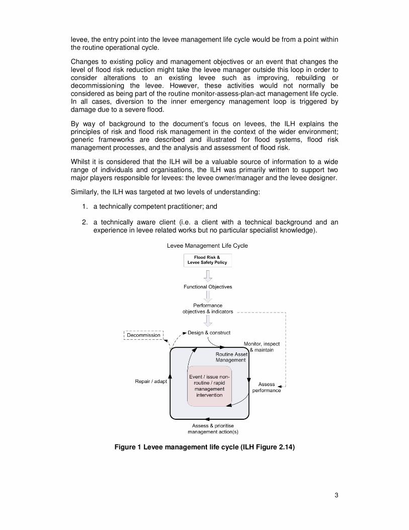
The above debate led to the evolution of the levee management life cycle (Figure 1). The levee life cycle diagram shows that in the case of a new levee, the normal entry point to the cycle would be from a policy decision and the definition of functional objectives (i.e. from the top of the diagram). In contrast, in the case of an existing
3
levee, the entry point into the levee management life cycle would be from a point within the routine operational cycle.
Changes to existing policy and management objectives or an event that changes the level of flood risk reduction might take the levee manager outside this loop in order to consider alterations to an existing levee such as improving, rebuilding or decommissioning the levee. However, these activities would not normally be considered as being part of the routine monitor-assess-plan-act management life cycle. In all cases, diversion to the inner emergency management loop is triggered by damage due to a severe flood.
By way of background to the document’s focus on levees, the ILH explains the principles of risk and flood risk management in the context of the wider environment; generic frameworks are described and illustrated for flood systems, flood risk management processes, and the analysis and assessment of flood risk.
Whilst it is considered that the ILH will be a valuable source of information to a wide range of individuals and organisations, the ILH was primarily written to support two major players responsible for levees: the levee owner/manager and the levee designer.
Similarly, the ILH was targeted at two levels of understanding:
1. a technically competent practitioner; and
2. a technically aware client (i.e. a client with a technical background and an experience in levee related works but no particular specialist knowledge).
Figure 1 Levee management life cycle (ILH Figure 2.14)
4
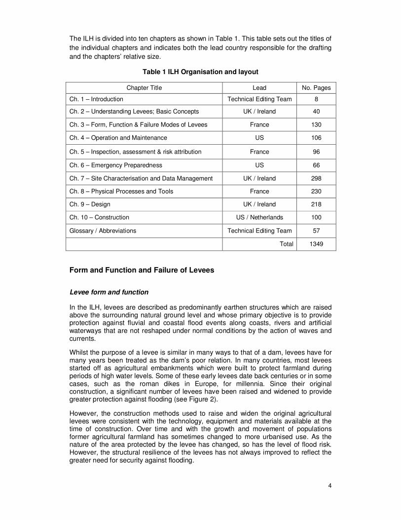
The ILH is divided into ten chapters as shown in Table 1. This table sets out the titles of
the individual chapters and indicates both the lead country responsible for the drafting
and the chapters’ relative size.
Table 1 ILH Organisation and layout
Chapter Title Lead No. Pages
Ch. 1 – Introduction Technical Editing Team 8
Ch. 2 – Understanding Levees; Basic Concepts UK / Ireland 40
Ch. 3 – Form, Function & Failure Modes of Levees France 130
Ch. 4 – Operation and Maintenance US 106
Ch. 5 – Inspection, assessment & risk attribution France 96
Ch. 6 – Emergency Preparedness US 66
Ch. 7 – Site Characterisation and Data Management UK / Ireland 298
Ch. 8 – Physical Processes and Tools France 230
Ch. 9 – Design UK / Ireland 218
Ch. 10 – Construction US / Netherlands 100
Glossary / Abbreviations Technical Editing Team 57
Total 1349
Form and Function and Failure of Levees
Levee form and function
In the ILH, levees are described as predominantly earthen structures which are raised above the surrounding natural ground level and whose primary objective is to provide protection against fluvial and coastal flood events along coasts, rivers and artificial waterways that are not reshaped under normal conditions by the action of waves and currents.
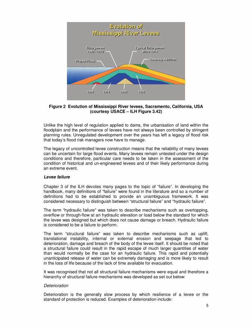
Whilst the purpose of a levee is similar in many ways to that of a dam, levees have for many years been treated as the dam’s poor relation. In many countries, most levees started off as agricultural embankments which were built to protect farmland during periods of high water levels. Some of these early levees date back centuries or in some cases, such as the roman dikes in Europe, for millennia. Since their original construction, a significant number of levees have been raised and widened to provide greater protection against flooding (see Figure 2).
However, the construction methods used to raise and widen the original agricultural levees were consistent with the technology, equipment and materials available at the time of construction. Over time and with the growth and movement of populations former agricultural farmland has sometimes changed to more urbanised use. As the nature of the area protected by the levee has changed, so has the level of flood risk. However, the structural resilience of the levees has not always improved to reflect the greater need for security against flooding.
5
Figure 2 Evolution of Mississippi River levees, Sacramento, California, USA (courtesy USACE – ILH Figure 3.42)
Unlike the high level of regulation applied to dams, the urbanisation of land within the floodplain and the performance of levees have not always been controlled by stringent planning rules. Unregulated development over the years has left a legacy of flood risk that today’s flood risk managers now have to manage.
The legacy of uncontrolled levee construction means that the reliability of many levees can be uncertain for large flood events. Many levees remain untested under the design conditions and therefore, particular care needs to be taken in the assessment of the condition of historical and un-engineered levees and of their likely performance during an extreme event.
Levee failure
Chapter 3 of the ILH devotes many pages to the topic of “failure”. In developing the handbook, many definitions of “failure” were found in the literature and so a number of definitions had to be established to provide an unambiguous framework. It was considered necessary to distinguish between “structural failure” and “hydraulic failure”.
The term “hydraulic failure” was taken to describe mechanisms such as overtopping, overflow or through-flow at an hydraulic elevation or load below the standard for which the levee was designed but which does not cause damage or breach. Hydraulic failure is considered to be a failure to perform.
The term “structural failure” was taken to describe mechanisms such as uplift, translational instability, internal or external erosion and seepage that led to deterioration, damage and breach of the body of the levee itself. It should be noted that a structural failure could result in the rapid escape of much larger quantities of water than would normally be the case for an hydraulic failure. This rapid and potentially unanticipated release of water can be extremely damaging and is more likely to result in the loss of life because of the lack of time available for evacuation.
It was recognised that not all structural failure mechanisms were equal and therefore a hierarchy of structural failure mechanisms was developed as set out below:
Deterioration
Deterioration is the generally slow process by which resilience of a levee or the standard of protection is reduced. Examples of deterioration include:
6
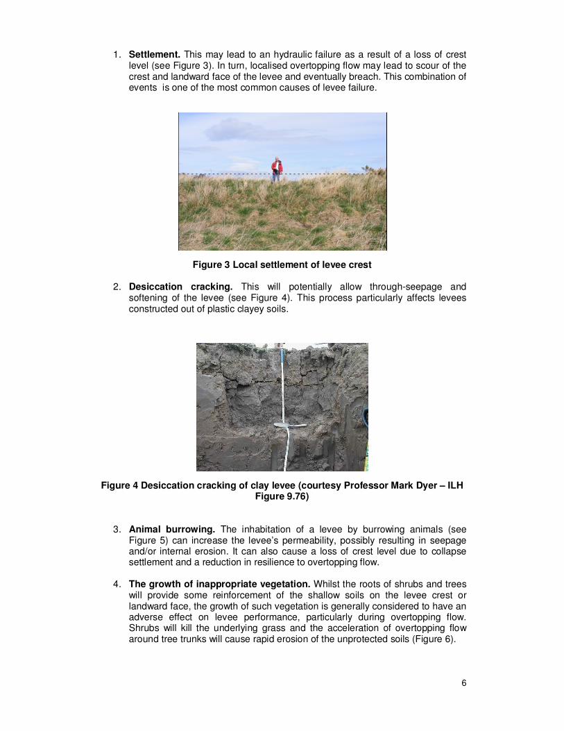
1. Settlement. This may lead to an hydraulic failure as a result of a loss of crest level (see Figure 3). In turn, localised overtopping flow may lead to scour of the crest and landward face of the levee and eventually breach. This combination of events is one of the most common causes of levee failure.
Figure 3 Local settlement of levee crest
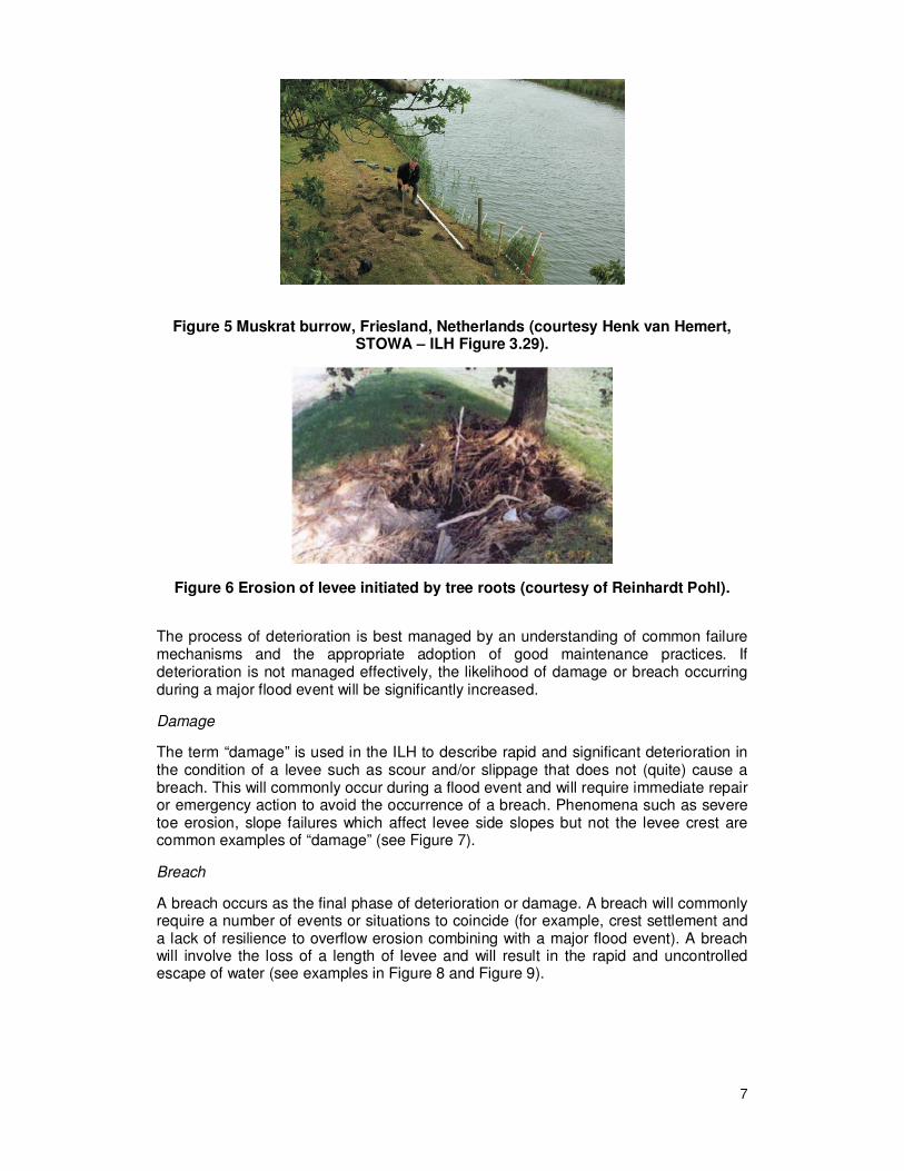
2. Desiccation cracking. This will potentially allow through-seepage and softening of the levee (see Figure 4). This process particularly affects levees constructed out of plastic clayey soils.
Figure 4 Desiccation cracking of clay levee (courtesy Professor Mark Dyer – ILH Figure 9.76)
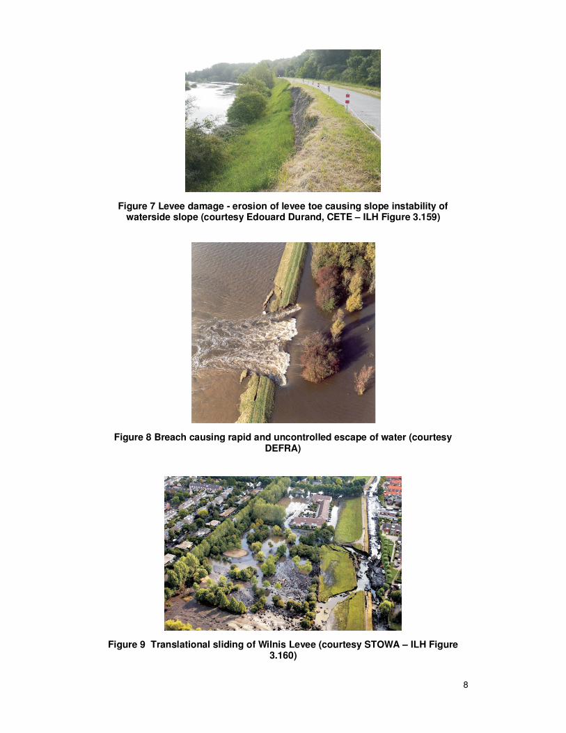
3. Animal burrowing. The inhabitation of a levee by burrowing animals (see Figure 5) can increase the levee’s permeability, possibly resulting in seepage and/or internal erosion. It can also cause a loss of crest level due to collapse settlement and a reduction in resilience to overtopping flow.
4. The growth of inappropriate vegetation. Whilst the roots of shrubs and trees will provide some reinforcement of the shallow soils on the levee crest or landward face, the growth of such vegetation is generally considered to have an adverse effect on levee performance, particularly during overtopping flow. Shrubs will kill the underlying grass and the acceleration of overtopping flow around tree trunks will cause rapid erosion of the unprotected soils (Figure 6).
7
Figure 5 Muskrat burrow, Friesland, Netherlands (courtesy Henk van Hemert, STOWA – ILH Figure 3.29).
Figure 6 Erosion of levee initiated by tree roots (courtesy of Reinhardt Pohl).
The process of deterioration is best managed by an understanding of common failure mechanisms and the appropriate adoption of good maintenance practices. If deterioration is not managed effectively, the likelihood of damage or breach occurring during a major flood event will be significantly increased.
Damage
The term “damage” is used in the ILH to describe rapid and significant deterioration in the condition of a levee such as scour and/or slippage that does not (quite) cause a breach. This will commonly occur during a flood event and will require immediate repair or emergency action to avoid the occurrence of a breach. Phenomena such as severe toe erosion, slope failures which affect levee side slopes but not the levee crest are common examples of “damage” (see Figure 7).
Breach
A breach occurs as the final phase of deterioration or damage. A breach will commonly require a number of events or situations to coincide (for example, crest settlement and a lack of resilience to overflow erosion combining with a major flood event). A breach will involve the loss of a length of levee and will result in the rapid and uncontrolled escape of water (see examples in Figure 8 and Figure 9).
8
Figure 7 Levee damage - erosion of levee toe causing slope instability of waterside slope (courtesy Edouard Durand, CETE – ILH Figure 3.159)
Figure 8 Breach causing rapid and uncontrolled escape of water (courtesy DEFRA)
Figure 9 Translational sliding of Wilnis Levee (courtesy STOWA – ILH Figure 3.160)
9
Time and causation chains are significant in distinguishing between the types of failure mechanisms described above. Commonly, a breach will occur as a result of a combination of factors. For example, a deterioration mechanism such as settlement over a long period of time could lead to premature overtopping flow in the event of a flood (hydraulic failure). If combined with a lack of resilience to external erosion (caused by other deterioration processes such as desiccation or the uncontrolled growth of inappropriate vegetation), this overtopping flow could rapidly lead to a breach (a structural failure).
It is noted that good maintenance is essential to reverse the impact of deterioration; without maintenance, the resilience of a levee to a flood event can be significantly reduced and may lead to, or accelerate, the process of damage or breach.
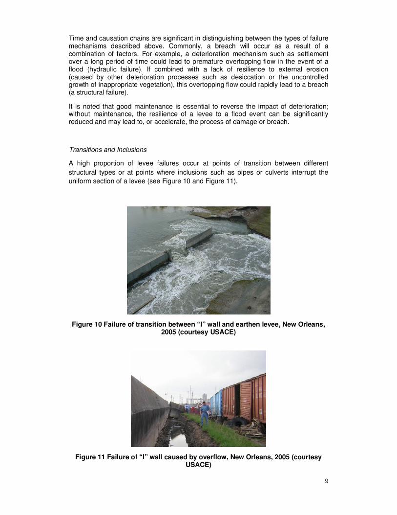
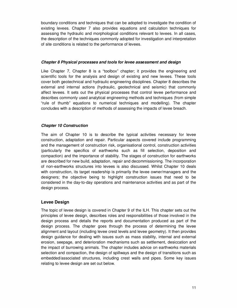
Transitions and Inclusions
A high proportion of levee failures occur at points of transition between different
structural types or at points where inclusions such as pipes or culverts interrupt the
uniform section of a levee (see Figure 10 and Figure 11).
Figure 10 Failure of transition between “I” wall and earthen levee, New Orleans, 2005 (courtesy USACE)
Figure 11 Failure of “I” wall caused by overflow, New Orleans, 2005 (courtesy USACE)

10
Managing Levees
Of the ten chapters of the ILH, Chapters 2 and 3 cover the fundamentals of levee use
and performance, whilst Chapters 4, 5 and 6 relate primarily to the operation and
maintenance of existing levees. Chapters 7 and 8 are “toolbox” chapters which present
methods for site characterisation and assessment, and ground investigation for levees
and describe calculation techniques for assessment or design purposes. Finally,
Chapters 9 and 10 cover the design and construction aspects of “change” (levee
adaptation or repair, new levee construction and decommissioning).
Given that the section of this report relating to form and function of levees relates to
Chapters 2 and 3, and the issue of design (Chapter 9) will be covered in more detail
subsequently, only brief descriptions of ILH Chapters 4 to 8 and 10 are provided below.
Chapter 4 Operation and maintenance
Chapter 4 addresses the operation and maintenance aspects of managing existing
levees. The issues covered by the chapter include organisational aspects and the
management of encroachments and vegetation on the levee. Maintenance
requirements for levees are described; these are related to the identification and repair
of defects arising from the processes of deterioration and damage.
Chapter 5 Levee inspection, assessment and risk attribution
This chapter covers levee assessment-related activities and their integration with the
levee management process. It provides a tiered approach to the assessment of levee
systems including risk analysis, assessment and inspection. Methods of data collection
are described including inspections, investigations and monitoring. Data management
systems to support levee management are also discussed in detail.
Chapter 6 Emergency management and operations
Chapter 6 sets out the principles of emergency management for levees. The chapter
provides details on issues such as preparedness and response and sets these into the
overall levee management process. It describes emergency intervention techniques
and covers both the emergency equipment and methods for minimising levee
overtopping and damage. The chapter also covers techniques that can be adopted for
the closure of breaches and for subsequent emergency repair works.
Chapter 7 Site characterisation and data requirements
This “toolbox” chapter opens with a description of the basic principles of site
characterisation for levees and their environment. Thereafter, the majority of the
chapter is focused on providing detailed descriptions of investigation and analysis
techniques for levees. These include works to establish hydraulic and geotechnical
11
boundary conditions and techniques that can be adopted to investigate the condition of
existing levees. Chapter 7 also provides equations and calculation techniques for
assessing the hydraulic and morphological conditions relevant to levees. In all cases,
the description of the techniques commonly adopted for investigation and interpretation
of site conditions is related to the performance of levees.
Chapter 8 Physical processes and tools for levee assessment and design
Like Chapter 7, Chapter 8 is a “toolbox” chapter; it provides the engineering and
scientific tools for the analysis and design of existing and new levees. These tools
cover both geotechnical and hydraulic engineering disciplines. Chapter 8 describes the
external and internal actions (hydraulic, geotechnical and seismic) that commonly
affect levees. It sets out the physical processes that control levee performance and
describes commonly used analytical engineering methods and techniques (from simple
“rule of thumb” equations to numerical techniques and modelling). The chapter
concludes with a description of methods of assessing the impacts of levee breach.
Chapter 10 Construction
The aim of Chapter 10 is to describe the typical activities necessary for levee
construction, adaptation and repair. Particular aspects covered include programming
and the management of construction risk, organisational control, construction activities
(particularly the specifics of earthworks such as fill selection, deposition and
compaction) and the importance of stability. The stages of construction for earthworks
are described for new build, adaptation, repair and decommissioning. The incorporation
of non-earthworks structures into levees is also discussed. Whilst Chapter 10 deals
with construction, its target readership is primarily the levee owner/managers and the
designers; the objective being to highlight construction issues that need to be
considered in the day-to-day operations and maintenance activities and as part of the
design process.
Levee Design
The topic of levee design is covered in Chapter 9 of the ILH. This chapter sets out the
principles of levee design, describes roles and responsibilities of those involved in the
design process and details the reports and documentation produced as part of the
design process. The chapter goes through the process of determining the levee
alignment and layout (including levee crest levels and levee geometry). It then provides
design guidance for dealing with issues such as mass stability, internal and external
erosion, seepage, and deterioration mechanisms such as settlement, desiccation and
the impact of burrowing animals. The chapter includes advice on earthworks materials
selection and compaction, the design of spillways and the design of transitions such as
embedded/associated structures, including crest walls and pipes. Some key issues
relating to levee design are set out below.
12
Levee Classification
At the time of writing the ILH, most participating countries did not have a system of risk
categorisation for levees. By adopting processes used for risk categorisation of dams,
a categorisation system for levees was developed. This allowed levees to be assessed
against key issues so that the appropriate investigative and design effort could be
determined on the basis of the resulting score.
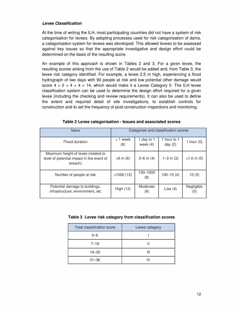
An example of this approach is shown in Tables 2 and 3. For a given levee, the
resulting scores arising from the use of Table 2 would be added and, from Table 3, the
levee risk category identified. For example, a levee 2.5 m high, experiencing a flood
hydrograph of two days with 90 people at risk and low potential other damage would
score 4 + 2 + 4 + 4 = 14, which would make it a Levee Category II. The ILH levee
classification system can be used to determine the design effort required for a given
levee (including the checking and review requirements). It can also be used to define
the extent and required detail of site investigations, to establish controls for
construction and to set the frequency of post-construction inspections and monitoring.
Table 2 Levee categorisation - Issues and associated scores
Issue Categories and classification scores
Flood duration > 1 week
(6)
1 day to 1
week (4)
1 hour to 1
day (2) 1 hour (0)
Maximum height of levee (related to
level of potential impact in the event of
breach)
>6 m (6) 3–6 m (4) 1–3 m (2) <1.0 m (0)
Number of people at risk >1000 (12) 100–1000
(8) 100–10 (4) 10 (0)
Potential damage to buildings,
infrastructure, environment, etc High (12)
Moderate
(8) Low (4)
Negligible
(0)
Table 3 Levee risk category from classification scores
Total classification score Levee category
0–6 I
7–18 II
19–30 III
31–36 IV
13
Crest height and freeboard
In addition to setting the alignment of the levee, the design process must define the
levee cross sectional geometry including the crest height.
The setting of minimum crest elevations usually requires a series of calculations and
the hydraulic modelling of flow rates and water levels in a river for a range of return
periods. Once this information is available, one of two approaches (either deterministic
or probabilistic) is used to determine the minimum levee crest elevations.
Historically, many levees have been designed to incorporate an additional height,
called freeboard, over and above the minimum crest level. This has been done to
provide additional resilience to wave overtopping, to levee deterioration phenomena
such as settlement and to provide a margin against other uncertainties (such as
variations in ground conditions).
Definitions for freeboard vary from country to country because it is a matter of design.
In Germany, for example, freeboard is the vertical distance between the crest on the
waterside and the design flood level resulting from the protection level plus wind set-up
plus wave run-up plus super-elevations due to settlement, subsidence and road or
other surfacings etc. In contrast, hydrologic or hydraulic uncertainties are covered in
the design water level.
As a general rule, in the USA, freeboard includes two components. The first is to
provide an uncertainty allowance or confidence factor in the determined design water
level. The second is to compensate for physical effects that can be quantified by
calculation or measurement (such as settlement, depth of desiccation cracks, wave
heights for rivers, etc.). For example, historically, in the USA, urban levees have been
required to have a minimum of 3 ft (1 m) freeboard, compared to agricultural levees.
Commonly in the UK, a nominal freeboard of between 300 mm and 1 m has been
applied to cover “wave height and settlement”.
However, the simple requirements described above are potentially vague and may
discourage the determination of the final design crest level in a rigorous manner.
Furthermore, it may complicate proper assessment of the requirements for levee
superiority. For these reasons, the requirement for a freeboard to be incorporated into
a design is gradually being replaced by a requirement for designers to set construction
crest levels from a risk-based assessment of the likelihood and consequences of levee
overflow and realistic predictions of levee behaviour and performance (such as
settlement of the crest with time).
Designing levees in environmentally sensitive areas
Designers of levee schemes in environmentally sensitive areas can face a number of
hard decisions. New levees or levee improvement works can interfere with or
potentially damage fragile eco-systems. The levee designer can face a choice between
providing the required level of flood defence or protecting sensitive habitats.
Designers working on the Natomas Levee Improvement Program (the NLIP) had just
such choices to make. By combining a conservation strategy with the multiple technical
objectives at an early stage, they were able to meet the flood management objectives
14
whilst still increasing the extent and connectivity of habitat lands in the Natomas Basin,
and offseting pre-project habitat losses for federal and state-listed endangered species.
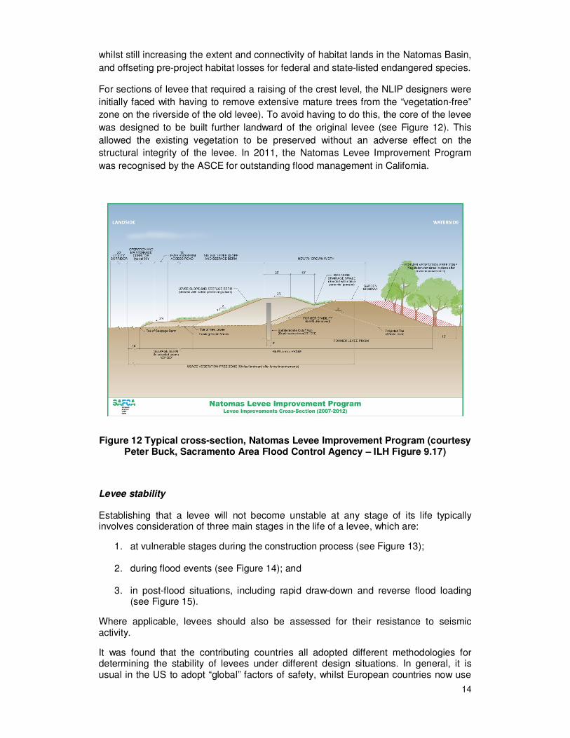
For sections of levee that required a raising of the crest level, the NLIP designers were
initially faced with having to remove extensive mature trees from the “vegetation-free”
zone on the riverside of the old levee). To avoid having to do this, the core of the levee
was designed to be built further landward of the original levee (see Figure 12). This
allowed the existing vegetation to be preserved without an adverse effect on the
structural integrity of the levee. In 2011, the Natomas Levee Improvement Program
was recognised by the ASCE for outstanding flood management in California.
Figure 12 Typical cross-section, Natomas Levee Improvement Program (courtesy Peter Buck, Sacramento Area Flood Control Agency – ILH Figure 9.17)
Levee stability
Establishing that a levee will not become unstable at any stage of its life typically involves consideration of three main stages in the life of a levee, which are:
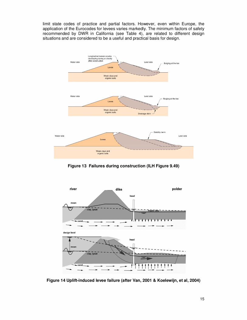
1. at vulnerable stages during the construction process (see Figure 13);
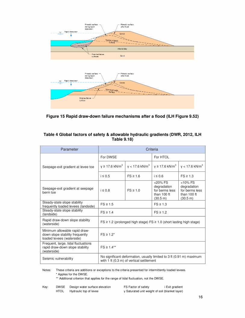
2. during flood events (see Figure 14); and
3. in post-flood situations, including rapid draw-down and reverse flood loading (see Figure 15).
Where applicable, levees should also be assessed for their resistance to seismic activity.
It was found that the contributing countries all adopted different methodologies for determining the stability of levees under different design situations. In general, it is usual in the US to adopt “global” factors of safety, whilst European countries now use
15
limit state codes of practice and partial factors. However, even within Europe, the application of the Eurocodes for levees varies markedly. The minimum factors of safety recommended by DWR in California (see Table 4), are related to different design situations and are considered to be a useful and practical basis for design.
Figure 13 Failures during construction (ILH Figure 9.49)
Figure 14 Uplift-induced levee failure (after Van, 2001 & Koelewijn, et al, 2004)
16
Figure 15 Rapid draw-down failure mechanisms after a flood (ILH Figure 9.52)
Table 4 Global factors of safety & allowable hydraulic gradients (DWR, 2012, ILH Table 9.18)
Parameter Criteria
Seepage-exit gradient at levee toe
For DWSE For HTOL
γ ≥ 17.6 kN/m3 γ < 17.6 kN/m
3 γ ≥ 17.6 kN/m
3 γ < 17.6 kN/m
3
i ≤ 0.5 FS ≥ 1.6 i ≤ 0.6 FS ≥ 1.3
Seepage-exit gradient at seepage berm toe
i ≤ 0.8 FS ≥ 1.0
<20% FS degradation for berms less than 100 ft (30.5 m)
<10% FS degradation for berms less than 100 ft (30.5 m)
Steady-state slope stability frequently loaded levees (landside)
FS ≥ 1.5 FS ≥ 1.3
Steady-state slope stability (landside)
FS ≥ 1.4 FS ≥ 1.2
Rapid draw-down slope stability (waterside)
FS ≥ 1.2 (prolonged high stage) FS ≥ 1.0 (short lasting high stage)
Minimum allowable rapid draw-down slope stability frequently loaded levees (waterside)
FS ≥ 1.2*
Frequent, large, tidal fluctuations rapid draw-down slope stability (waterside)
FS ≥ 1.4**
Seismic vulnerability No significant deformation, usually limited to 3 ft (0.91 m) maximum with 1 ft (0.3 m) of vertical settlement
Notes: These criteria are additions or exceptions to the criteria presented for intermittently loaded levees.
* Applies for the DWSE.
** Additional criterion that applies for the range of tidal fluctuation, not the DWSE.
Key: DWSE Design water surface elevation FS Factor of safety i Exit gradient
HTOL Hydraulic top of levee γ Saturated unit weight of soil (blanket layer)
17
Earthworks design for levees
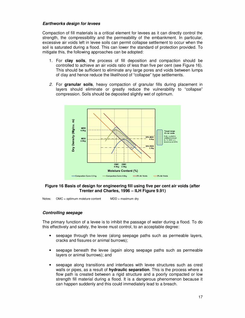
Compaction of fill materials is a critical element for levees as it can directly control the strength, the compressibility and the permeability of the embankment. In particular, excessive air voids left in levee soils can permit collapse settlement to occur when the soil is saturated during a flood. This can lower the standard of protection provided. To mitigate this, the following approaches can be adopted:
1. For clay soils, the process of fill deposition and compaction should be controlled to achieve an air voids ratio of less than five per cent (see Figure 16). This should be sufficient to eliminate any large pores and voids between lumps of clay and hence reduce the likelihood of “collapse” type settlements.
2. For granular soils, heavy compaction of granular fills during placement in layers should eliminate or greatly reduce the vulnerability to “collapse” compression. Soils should be deposited slightly wet of optimum.
Figure 16 Basis of design for engineering fill using five per cent air voids (after Trenter and Charles, 1996 – ILH Figure 9.91)
Notes: OMC = optimum moisture content MDD = maximum dry
Controlling seepage
The primary function of a levee is to inhibit the passage of water during a flood. To do this effectively and safely, the levee must control, to an acceptable degree:
• seepage through the levee (along seepage paths such as permeable layers, cracks and fissures or animal burrows);
• seepage beneath the levee (again along seepage paths such as permeable layers or animal burrows); and
• seepage along transitions and interfaces with levee structures such as crest walls or pipes, as a result of hydraulic separation. This is the process where a flow path is created between a rigid structure and a poorly compacted or low strength fill material during a flood. It is a dangerous phenomenon because it can happen suddenly and this could immediately lead to a breach.
18
Each of these features has the potential to cause deterioration in the performance of the levee or trigger a breach. The impact of seepage needs to be considered from two main aspects – sudden failure and ongoing deterioration.
First, hydraulic and phreatic pressures can directly trigger a sudden failure as follows:
• The hydraulic action could apply a direct horizontal load onto a levee, sufficient to cause a translational failure.
• High phreatic pressure within the body of the levee could cause sudden rotational failure of the levee (slope instability).
• Groundwater pressure acting in an aquifer beneath the landward levee toe, and linked to the flood level, could create an uplift which could initiate instability of the levee or create a sufficiently adverse hydraulic gradient to cause sand boils.
• Hydraulic separation caused by poor detailing or poor construction could cause immediate failure or could trigger rapid deterioration through internal erosion.
Secondly, seepage can cause ongoing deterioration and problems such as leakage, crest settlement and minor flooding. If this deterioration is not managed, it can create internal erosion which could over time lead to breach.
The issue of designing to avoid hydraulic separation is discussed in Section 9.15 of the ILH (“Associated Structures”) as it is usually associated with hydraulic fracture between the levee and stiff embedded structures. The ILH also provides guidance for the design of measures that are commonly used to assess and control seepage.
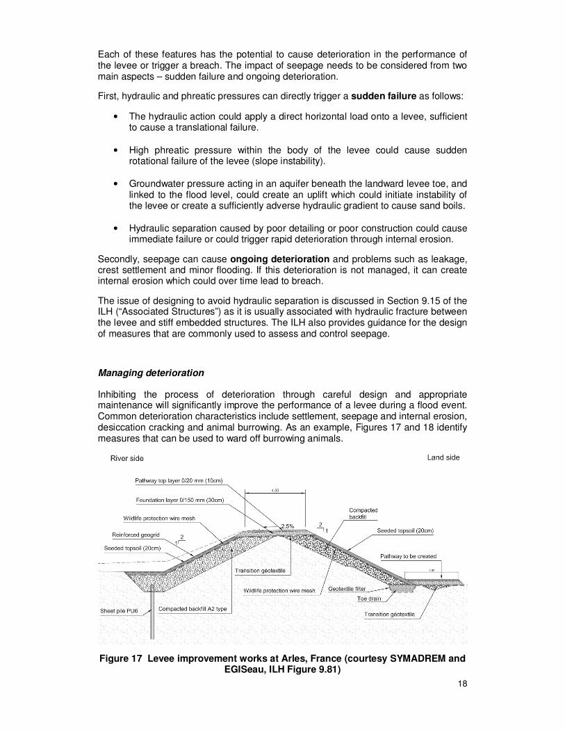
Managing deterioration
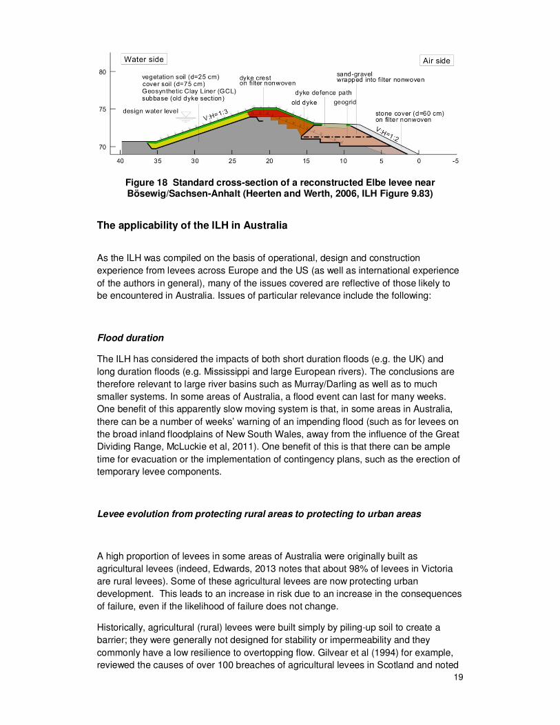
Inhibiting the process of deterioration through careful design and appropriate maintenance will significantly improve the performance of a levee during a flood event. Common deterioration characteristics include settlement, seepage and internal erosion, desiccation cracking and animal burrowing. As an example, Figures 17 and 18 identify measures that can be used to ward off burrowing animals.
Figure 17 Levee improvement works at Arles, France (courtesy SYMADREM and EGISeau, ILH Figure 9.81)
19
Figure 18 Standard cross-section of a reconstructed Elbe levee near Bösewig/Sachsen-Anhalt (Heerten and Werth, 2006, ILH Figure 9.83)
The applicability of the ILH in Australia
As the ILH was compiled on the basis of operational, design and construction
experience from levees across Europe and the US (as well as international experience
of the authors in general), many of the issues covered are reflective of those likely to
be encountered in Australia. Issues of particular relevance include the following:
Flood duration
The ILH has considered the impacts of both short duration floods (e.g. the UK) and
long duration floods (e.g. Mississippi and large European rivers). The conclusions are
therefore relevant to large river basins such as Murray/Darling as well as to much
smaller systems. In some areas of Australia, a flood event can last for many weeks.
One benefit of this apparently slow moving system is that, in some areas in Australia,
there can be a number of weeks’ warning of an impending flood (such as for levees on
the broad inland floodplains of New South Wales, away from the influence of the Great
Dividing Range, McLuckie et al, 2011). One benefit of this is that there can be ample
time for evacuation or the implementation of contingency plans, such as the erection of
temporary levee components.
Levee evolution from protecting rural areas to protecting to urban areas
A high proportion of levees in some areas of Australia were originally built as
agricultural levees (indeed, Edwards, 2013 notes that about 98% of levees in Victoria
are rural levees). Some of these agricultural levees are now protecting urban
development. This leads to an increase in risk due to an increase in the consequences
of failure, even if the likelihood of failure does not change.
Historically, agricultural (rural) levees were built simply by piling-up soil to create a
barrier; they were generally not designed for stability or impermeability and they
commonly have a low resilience to overtopping flow. Gilvear et al (1994) for example,
reviewed the causes of over 100 breaches of agricultural levees in Scotland and noted
20
that virtually every overtopped levee breached. If levees change from protecting rural
areas to urban developments as a result of land development in the protected areas,
their performance should be carefully re-assessed; remedial works may be required to
improve performance to match the higher risk profile. The ILH presents examples of
how this process has been carried out and provides design guidance for the various
issues that need to be considered.
Balancing risk and expenditure
Approximately 70% of the Netherlands is below sea level. Flood defence in the
Netherlands is therefore a vital part of the fabric of Dutch society; the design,
construction, management and maintenance of levees (dikes) is governed by Dutch
law and engineering procedures are highly prescriptive. For example, some sea dikes
are designed for return periods of 1 in 10,000 years. However, elsewhere in much of
Europe and in the US, whilst flood risk management is important, there is insufficient
funding for the “absolute” approach adopted in the Netherlands. Flood risk
management is therefore generally funded on the basis of tiered risk and cost-
effectiveness assessments. This model is also commonly adopted in Australia.
In New South Wales, very few urban levees have been designed for floods larger than
the 1% Annual Exceedance Probability (AEP) or the 1 in 100 years Average
Recurrence Interval (ARI) event. A number of levees have been constructed with
design floods lower than the 1% AEP event, down as low as the 10% AEP (1 in 10
years ARI) for some urban areas and much lower again in some coastal rural areas,
such as the Lower Macleay River (Mark et al, 2010).
For some coastal towns where flood heights vary markedly with changes in AEP,
providing protection up to the 1% AEP level may be difficult to justify economically and
may create major practical difficulties due to a range of issues including the width of the
levee footprint where the space available for levee construction is limited (Mark et al,
2010). Under such circumstances, it may be cost effective to provide protection against
relatively small (but frequent) flood events to restrict property damage and community
disruption. However, as stated by Mark et al (2010), such judgements only relate to
property damage of community disruption; no levees in NSW have been justified on the
basis of the number of lives that might be saved or injuries avoided.
The levee at Lismore in NSW is an example of a design that was based on a lower
standard of defence. The levee was completed in 2005 and was designed for a 10%
AEP (1 in 10 years) flood. This levee has reduced the significant impact of several
floods and avoided both millions of dollars worth of damage and greatly mitigated the
impacts of flooding (McLuckie et al, 2011).
The issue of “freeboard” proved contentious during the drafting of the ILH; some
countries preferred to keep a minimum freeboard dimension on top of design levels
whilst others moved towards a crest level established on a probabilistic basis (i.e. the
margin between the design level and the physical top of the levee being fixed by an
extreme water level established on the basis of a probabilistic assessment). Freeboard
in levees is generally provided for a mixture of factors including construction
21
settlement, wind wave action, and local hydraulic effects. In Australia, it is recognised
that the tops of levees can be desiccated and cracked during dry periods. Therefore, if
a freeboard exists, it is generally not relied upon to provide protection in excess of the
design flood level (Mark et al, 2010).
Selection of construction materials
Given the relative remoteness of some levees in Australia, it is common for levee
constructors to make use of fill materials that are available as close as possible to the
levee construction site. These materials may not be best suited to levee construction
and this can leave the levee vulnerable to deterioration or to poor performance during a
flood. For example, granular soils can be susceptible to overflow erosion or seepage
and internal erosion whilst highly plastic clays can be susceptible to desiccation
cracking as they dry out in warm and dry periods of weather (Mark et al, 2010). The
resulting desiccation cracks can cross the levee near to the levee surface and these
cracks can form conduits for water flow during a flood. This can lead to seepage,
internal erosion and softening, all of which will adversely affect levee performance.
Similarly, dispersive or permeable foundation material may lead to uncontrolled
seepage, levee slumping and/or piping, when no appropriate measures are in place.
All of these processes of deterioration and poor performance are described in the ILH.
The ILH also presents methodologies for overcoming problems associated with poor
quality fill material and accommodating unsuitable fill materials in levee construction.
Levee deterioration and visual inspection
As stated by McLuckie et al (2011), a levee is only as strong as its weakest link;
inadequate routine maintenance of urban levees leaves levees vulnerable to
deterioration which could adversely affect their performance during a flood event.
Regular and frequent visual inspections and audits undertaken by suitably qualified and
experienced engineering technical staff are seen the most cost effective way of
identifying (and thereby managing) potential problems (NSW Public Works, 2013). The
results of levee auditing need to inform levee operations and maintenance (McLuckie
et al 2014).
Managing vegetation
The issue of vegetation management was a matter of extensive debate during the
development of the ILH. It was particularly difficult to find a balance between the
optimum vegetation from a performance point of view and the environmental benefits of
established and mature waterside habitat. The existence of unsuitable vegetation such
as trees and shrubs, the inhabitation of levees by burrowing animals and phenomena
such as desiccation have adverse effects on levee performance. However, dealing
with these issues robustly can have a significant environmental impact. The ILH
22
presents a number of examples where designers found ways of maintaining sensitive
habitats whilst creating levees to perform in accordance with their design requirements.
The design of levees should consider the impact of climatic conditions on performance.
Issues that relate to maintenance of the levee so that it attains its design requirements
(such as limited water supply during dry spells and the level of resources required)
should be considered as part of the levee design. For example, significant rainfall
and/or an artificial water supply are essential for maintenance of good quality grass
cover on the levee. In dry inland areas of Australia, consideration could be given to
other types of surface protection in lieu of the grass cover. These may include the use
of reinforced or synthetic grass for erosion control.
Summary and Conclusions
The International Levee Handbook (the ILH) is a compendium of good practice which
offers comprehensive guidance on the design, construction, maintenance and
improvement of levees. It was compiled by an international team from France, USA
and UK/Ireland supported by Netherlands and Germany.
The ILH was written by levee practitioners and experts; the process of its development
facilitated mutual lesson-learning between the participating countries in the project
consortium. The ILH was written for levee owner/operators as well as designers; it
offers a decision support framework rather than being a prescriptive code of practice
and it covers the issues and challenges that can be faced during the complete levee
life cycle.
Given the international nature of the drafting panel of the ILH, the handbook is
considered to contain much of relevance to the topic of levee maintenance,
assessment, investigation, design and construction in Australia as well as being a
useful summary of levee specific issues such as the development of emergency
procedures. In total, the ILH represents the work of more than 100 individuals; the
process of producing the handbook has effectively created an international community
of practice for those working with levees. It is hoped that this community of practice will
expand to incorporate individuals from other nations that were not directly involved with
the original project and that it will continue to share both knowledge and good practice
on an international basis.
References
CIRIA, Ministry of Ecology, USACE, (2013). The International Levee Handbook (Report C731). Go to: http://www.leveehandbook.net/index.asp.
Department of Water Resources (DWR), (2012). Urban levee design criteria, ETL 1110-2-580,
California Department of Water Resources, California. Go to:
www.water.ca.gov/floodsafe/leveedesign/ULDC_May2012.pdf.
Edwards, M., (2013). Resolving problems with flood mitigation infrastructure – responding to
community needs. 53rd
Annual Floodplain Authorities Conference, Tweed Heads, NSW.
Gilvear, D.J., Davies, J.R. and Winterbottom, S.J., (1994). Mechanisms of floodbank failure
during large flood events on the rivers Tay and Earn, Scotland. Quarterly Journal of
Engineering Geology and Hydrogeology, Vol. 27, No. 4, pp 319 - 332.
23
Heerten, G. & Werth, K., (2006). Anwendung von Geokunststoffen bei der Deichertüchtigung,
Fachtagung Deichertüchtigung und Deichverteidigung in Bayern, Hrsg. Institut für Wasserbau
und Wasserwirtschaft, TU München, Wallgau, Germany.
Mark, I., McLuckie, D. & Opper, S., (2010). Why should I evacuate when the levee isn’t
predicted to overtop? 50th Annual Floodplain Authorities Conference, Gosford, NSW.
McLuckie, D., Spain, F. & Dixon, J., (2014). Monitoring the condition of levees to inform decision
making. 54th Annual Floodplain Authorities Conference, Deniliquin, NSW.
McLuckie, D., Spain, F. & Dixon, J., (2011). Monitoring the condition of levees to inform decision
making. 51st Annual Floodplain Authorities Conference, Narooma, NSW.
NSW Public Works (OEH), (2013). Development of methodology and visual audit for urban
levees. Report No. DC13004, NSW Public Works.
Trenter, N.A. & Charles, J.A., (1996). A model specification for engineered fills for building purposes. Proceedings of Institution of Civil Engineers – Geotechnical Engineering, Vol. 119, pp. 219–230. Institution of Civil Engineers, Thomas Telford, UK.