adaptable all -composite bridge...
TRANSCRIPT
John Unser, Prakash Kumar, K. Chandrashekhara, Antonio Nanni and Steve Watkins, “Adaptable All-Composite Bridge Concept,’ Proceedings of the CFA Composites Conference, Paper No. 39, pp. 1-15, Las Vegas, NV, Sept. 26-30,2000.
1
Adaptable All-Composite Bridge Concept
Authors:
John Unser Composite Products Inc.
St. Louis, Missouri 63125
Prakash Kumar, K. Chandrashekhara, Antonio Nanni, and Steve Watkins
University of Missouri – Rolla Rolla, Missouri 65409
Abstract Composite Products Inc. (CPI) in conjunction with the University of Missouri – Rolla (UMR) designed and built an all-composite bridge that was installed at the UMR campus. The bridge spanned 30 feet and was 9 feet wide. The bridge was designed to AASHTO H20 load rating. UMR has conducted extensive Finite Element Analysis (FEA) and testing on the bridge. The building block of the bridge is a pultruded 3 inches square tube. The tubes was bonded and screwed together using adhesive to form eight layers. The first and seventh layers are carbon reinforced with inside and outside layers of ±45 stitched fiberglass mat. The matrix was vinyl ester resin with flame retardant additives. The carbon tubes were produced by CPI at Lemay Center for Composite Technology (LCCT). The remaining glass reinforced tubes were manufactured by Bedford Reinforced Plastics. CPI assembled the bridge at LCCT and was transported in one piece to UMR. The bridge has fiber optic sensors built into the structure. The paper gives an overview of the project summarizing the FEA; component testing; static and fatigue testing of bridge main structural element; and installation.
John Unser, Prakash Kumar, K. Chandrashekhara, Antonio Nanni and Steve Watkins, “Adaptable All-Composite Bridge Concept,’ Proceedings of the CFA Composites Conference, Paper No. 39, pp. 1-15, Las Vegas, NV, Sept. 26-30,2000.
2
Introduction In recent years, problems with the nation’s aging and the rapidly deteriorating bridge infrastructure has prompted a resurgence in research and development of new and more durable design materials. The American Association of State Highway and Transportation Officials (AASHTO) projected that just to maintain current bridge conditions, 200,000 bridges will need to be replaced or repaired during the next two decades (1). Composite materials may have applications in rehabilitation of existing bridges and complete structural replacement or new construction (2,3). Specifically, Fiber Reinforced Polymer (FRP) composite materials are being researched for application in bridge infrastructure renewal (4). FRP composites offer inherent advantages over traditional materials with regard to high strength-to-weight ratio, design flexibility, corrosion resistance, low maintenance, and extended service life. More than half of all bridges represent short span bridges on rural minor collectors and local roads and streets (5). The short span bridges are typically concrete box culverts, decks spanning end piers, and decks with girders underneath. Several reports have shown that most State Departments of Transportation (DOT) see deck replacement as a major concern. Wisconsin DOT stated that if painting is excluded, deck replacements account for 75 percent to 90 percent of maintenance costs (6). Because of this, the development of FRP bridge components has focused on bridge decks. To achieve a more adaptable system to replace all types of short span bridges, Composite Products Inc. (CPI) has developed in conjunction with the University of Missouri - Rolla (UMR) a FRP bridge system utilizing multi-layered pultruded tubes. The goal of the project was to develop a bridge design that utilizes standard pultruded components to assemble an adaptable bridge. The main component of the bridge was a three inches square tube reinforced with either glass or carbon fibers. These tubes were bonded together to form seven layers. The top and the bottom layers consisted of carbon reinforced tubes. To prove the feasibility of the design concept, the following tasks were performed: 1. Finite Element Analysis, 2. Manufacturing of Composite Tubes, 3. Test Article and Bridge Assembly, 4. Tube Assembly Load Tests, 5. Test Article Load Tests, and 6. Bridge Installation.
1. Finite Element Analysis The bridge deck was designed to AASHTO H-20 specifications for a 9.14 m (30 ft) span vehicular traffic bridge. AASHTO bridge design specifications limit the deflection of the deck to 1/800 of the span length, L, of the bridge deck. According to the specifications, the flexural members of the bridge structures should be designed to have adequate stiffness to limit deflections or any deformations that may adversely affect the strength or serviceability of the structure. The live load distribution was based on one AASHTO H-20 truckload with two back axels positioned equidistance on either side of the center of the bridge deck. The service load of an H-20 truck was calculated as 142.4 kN (32,000 lb) with 71.2 kN (16,000 lb) on each back axel. The allowable deflection for a 9.14 m (30 ft) bridge span was less than 11.4 mm (0.45 in). To account for neglected loading, load multipliers, and material strength reduction factors, a conservative factor of safety of three was used for the design of the composite bridge.
John Unser, Prakash Kumar, K. Chandrashekhara, Antonio Nanni and Steve Watkins, “Adaptable All-Composite Bridge Concept,’ Proceedings of the CFA Composites Conference, Paper No. 39, pp. 1-15, Las Vegas, NV, Sept. 26-30,2000.
3
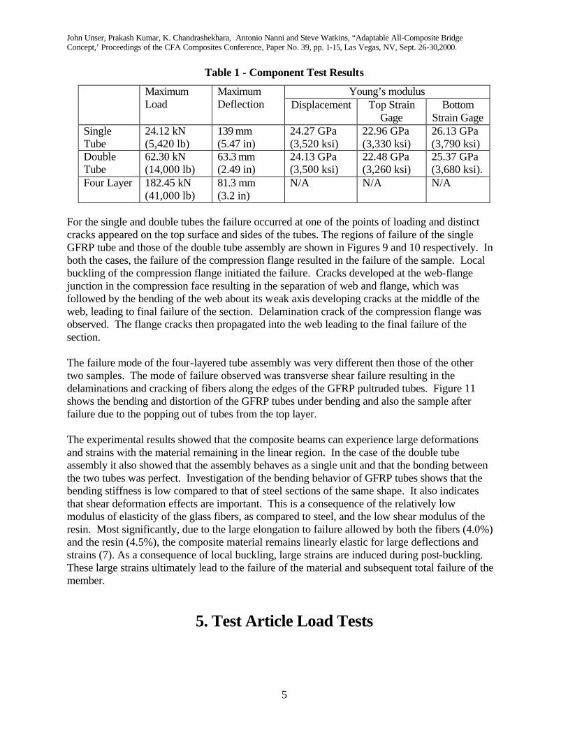
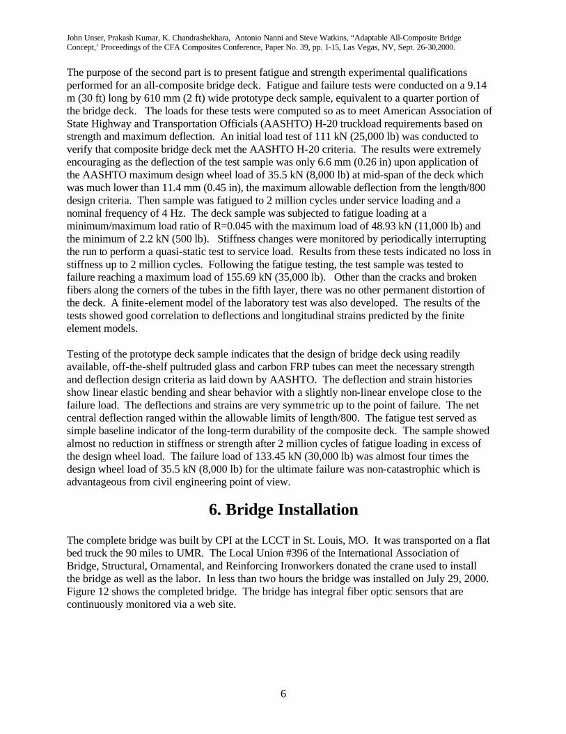
Extensive Finite Element Analysis (FEA) was conducted on the bridge components, assemblies, and bridge deck at UMR. A three-dimensional finite element model using ABAQUS commercial package was used to analyze a single tube, double tube, four layer, test beam, and bridge deck. Based on the analysis and testing it was determined to meet the deflection criteria that the carbon fiber layers had to be fifteen inches apart or five tubes. To save material an I-beam configuration was adopted. Figure 1 shows an example of the model of the bridge deck. The design of the bridge deck consisted of four identical I-beams running along the length of the deck. A schematic of the cross section is presented in Figure 2. In this paper the layers of tubes have been numbered from the top to the bottom of the deck with the topmost layer being the first layer and the bottom layer of tubes being the seventh layer of the deck. The first and seventh layers consisted of 9.14 m (30 ft) long carbon fiber-reinforced polymer (CFRP) tubes that were used to impart stiffness to the structure. The remaining five layers were made up of glass fiber reinforced polymer (GFRP) tubes. The second and sixth layers were built using 2.74 m (9 ft) long tubes. The third, forth and fifth layers of tubes formed the neck or web of the I-beams. The third and fifth layers were assembled using 9.14 m (30 ft) long tubes while the fourth layer, the center layer in the neck of the I-beam, was made up of 305 mm (1 ft) long tubes. The first, third, fifth and seventh layers were laid down parallel to the direction of the traffic and were the main load bearing members of the structure. The second, forth, and sixth layers were laid down transverse to the direction of traffic. These layers had very limited load carrying capacity and were used mainly to transmit load.
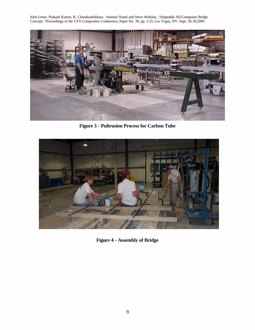
2. Manufacturing of Composite Tubes A major accomplishment under this program was the manufacturing of a carbon fiber reinforced pultruded tubes, which form the top and bottom layers of the bridge deck. These tubes are carbon reinforced (Zoltek Panex 33) with inside and outside layers of ±45 stitched mat (Fiber Glass Industries). The matrix is vinyl ester resin Derakane 411-350 (Dow Chemical) with Saytek 102E flame retardant (Albemarle Corporation). CPI produced these tubes utilizing a Koppernaus Micro Pultruder at LCCT. The pultrusion process is shown in Figure 3. Over 2,000 feet of the carbon reinforced tubes were produced for this project with the longest run being 1,600 feet.
3. Test Article and Bridge Assembly The assembly of the test articles and bridge deck was accomplished by CPI at the LCCT. Two test articles 2 feet by 30 feet and the bridge deck 9 feet by 30 feet were assembled. CPI produced the carbon tubes for the assemblies. The remaining glass reinforced tubes were manufactured by Bedford Reinforced Plastics using glass roving from Vetrotex America and CoRezyn resin from Interplastic Corporation. The tubes were bonded and screwed together using Hysol 9460 adhesive to form seven layers. Individual tubes were clamped to the adjacent tube already in the assembly and then screwed in place. This assembly process eliminated the need for jigs and fixtures. Figure 4 shows the assembly process. Fiber optic sensors were imbedded into the bridge structure during the assembly process at fifteen locations.
John Unser, Prakash Kumar, K. Chandrashekhara, Antonio Nanni and Steve Watkins, “Adaptable All-Composite Bridge Concept,’ Proceedings of the CFA Composites Conference, Paper No. 39, pp. 1-15, Las Vegas, NV, Sept. 26-30,2000.
4
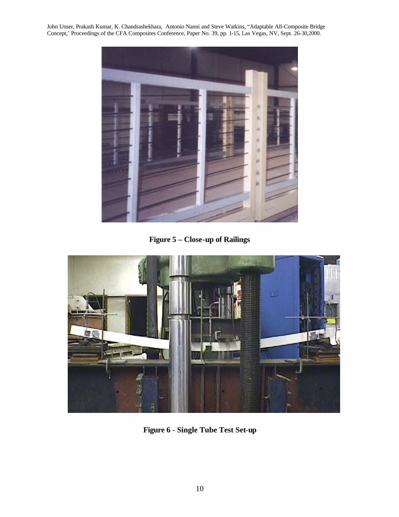
The bridge was designed for automotive use, but was being installed at the UMR campus as a pedestrian. A campus wide contest was conducted for the “look” of the bridge. The final design called for the railing to have railings that gave the look of a suspension bridge. Figure 5 shows a close up detail of the railings. Some unique features of the railings is that the arches are formed with carbon reinforced rods that utilize an epoxy resin modified with a soybean oil based additive. The rods were pultruded bye CPI at LCCT. CPI and UMR have been working on this soybean oil resin system for the past two years. Another unique item is that the plates that make up the columns are made CPI from recycled sheet molding compound (SMC) provided by The R.J. Marshall Company. A thin polymer concrete wearing surface (Transpo T-48) modified with a soybean oil based resin additive was added to the top of the full-size bridge deck. The bridge is a show case of new technology.
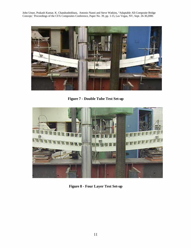
4. Tube Assembly Load Tests The performance evaluation of pultruded hollow tubes, tube assembly and all-composite bridge deck was investigated. The focus of the first part of the study was to provide structural design information pertaining to mechanical properties and failure modes of square hollow pultruded tubes made of glass fibers in vinyl ester resin when used as a primary load bearing member. The study also investigates the influence of shear, buckling, initial crookedness, and manufacturing defects (material non-uniformity or asymmetry) on the structural behavior of GFRP hollow tubes. Special emphasis was given to understand the modes of failure under static loading. Several coupons consisting of single, double and a four-layered tube assembly were tested under static flexural loading. The coupons consisted of 76 mm (3 in) square hollow pultruded GFRP tubes with a thickness of 6.35 mm (0.25 in). The coupons were tested to failure under flexural loading and data obtained for deflection and strain were evaluated. The results obtained were compared with those from the finite element analysis (FEA). The stress distribution and modes of failure, determined by the tests, were verified numerically. The validation model allows to investigate feasibility of the design and to predict the behavior of the bridge. The knowledge and data gained from these tests will be used to analyze the response of the GFRP composite materials and of various assemblies built out of it, especially with regard to bridge deck applications. The single tubes and the double tube assemblies were tested in four-point bending configuration, as shown in Figures 6 and 7, while the four-layered tube assembly was tested in three-point bending configuration, as show in Figure 8. The samples were tested in simply supported boundary conditions and were placed on rollers on both the ends spaced at a distance of 2.13 mm (7 ft) so that the sample extended 152.4 mm (6 in) beyond the support rollers at each end. The instrumentation of the samples consisted of LVDTs (Linear variable differential transformers) to measure displacement and strain gages on top of the tube and on bottom. The loading of the single tube was done in cycles of 6.68 kN (1,500 lb). For the double tube the loading cycle was increased to 13.35 kN (3,000 lb) while for the four-layered tube assembly the loading cycle was 22.25 kN (5,000 lb). The cyclic loading of the specimen was done so as to evaluate damage accumulation, stability and any residual deflection, strain or any energy loss occurring in it due to the applied load. All the three specimens were tested to failure. The test results for the GFRP tubes are presented in Table 1.
John Unser, Prakash Kumar, K. Chandrashekhara, Antonio Nanni and Steve Watkins, “Adaptable All-Composite Bridge Concept,’ Proceedings of the CFA Composites Conference, Paper No. 39, pp. 1-15, Las Vegas, NV, Sept. 26-30,2000.
5
Table 1 - Component Test Results
Young’s modulus Maximum Load
Maximum Deflection Displacement Top Strain
Gage Bottom
Strain Gage Single Tube
24.12 kN (5,420 lb)
139 mm (5.47 in)
24.27 GPa (3,520 ksi)
22.96 GPa (3,330 ksi)
26.13 GPa (3,790 ksi)
Double Tube
62.30 kN (14,000 lb)
63.3 mm (2.49 in)
24.13 GPa (3,500 ksi)
22.48 GPa (3,260 ksi)
25.37 GPa (3,680 ksi).
Four Layer 182.45 kN (41,000 lb)
81.3 mm (3.2 in)
N/A N/A N/A
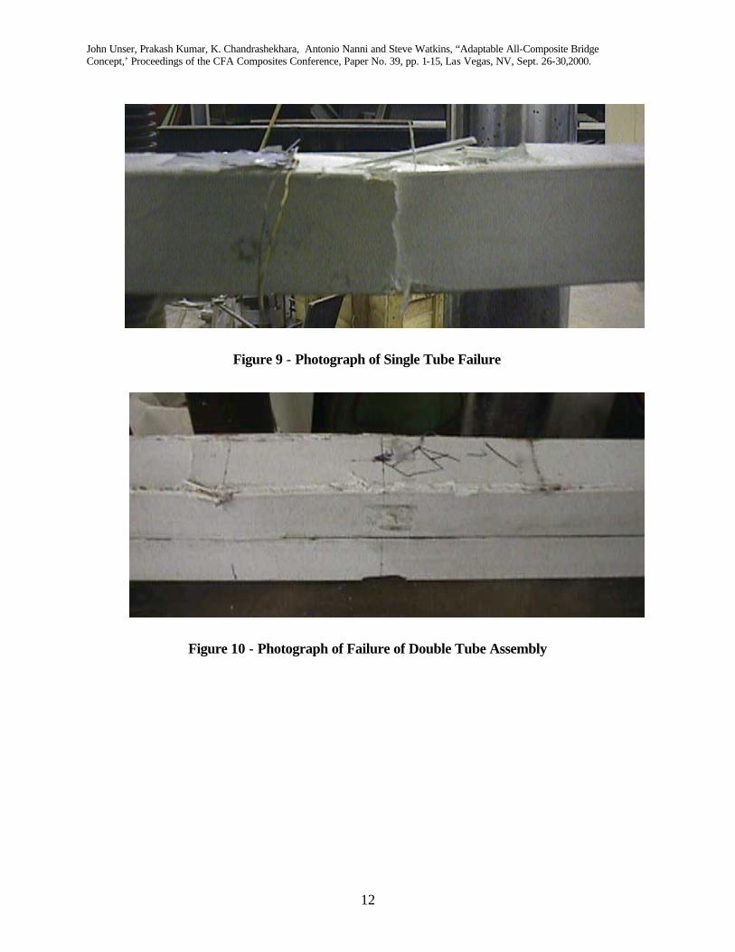
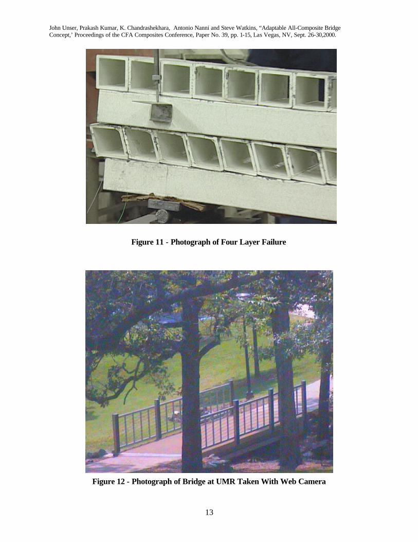
For the single and double tubes the failure occurred at one of the points of loading and distinct cracks appeared on the top surface and sides of the tubes. The regions of failure of the single GFRP tube and those of the double tube assembly are shown in Figures 9 and 10 respectively. In both the cases, the failure of the compression flange resulted in the failure of the sample. Local buckling of the compression flange initiated the failure. Cracks developed at the web-flange junction in the compression face resulting in the separation of web and flange, which was followed by the bending of the web about its weak axis developing cracks at the middle of the web, leading to final failure of the section. Delamination crack of the compression flange was observed. The flange cracks then propagated into the web leading to the final failure of the section. The failure mode of the four-layered tube assembly was very different then those of the other two samples. The mode of failure observed was transverse shear failure resulting in the delaminations and cracking of fibers along the edges of the GFRP pultruded tubes. Figure 11 shows the bending and distortion of the GFRP tubes under bending and also the sample after failure due to the popping out of tubes from the top layer. The experimental results showed that the composite beams can experience large deformations and strains with the material remaining in the linear region. In the case of the double tube assembly it also showed that the assembly behaves as a single unit and that the bonding between the two tubes was perfect. Investigation of the bending behavior of GFRP tubes shows that the bending stiffness is low compared to that of steel sections of the same shape. It also indicates that shear deformation effects are important. This is a consequence of the relatively low modulus of elasticity of the glass fibers, as compared to steel, and the low shear modulus of the resin. Most significantly, due to the large elongation to failure allowed by both the fibers (4.0%) and the resin (4.5%), the composite material remains linearly elastic for large deflections and strains (7). As a consequence of local buckling, large strains are induced during post-buckling. These large strains ultimately lead to the failure of the material and subsequent total failure of the member.
5. Test Article Load Tests
John Unser, Prakash Kumar, K. Chandrashekhara, Antonio Nanni and Steve Watkins, “Adaptable All-Composite Bridge Concept,’ Proceedings of the CFA Composites Conference, Paper No. 39, pp. 1-15, Las Vegas, NV, Sept. 26-30,2000.
6
The purpose of the second part is to present fatigue and strength experimental qualifications performed for an all-composite bridge deck. Fatigue and failure tests were conducted on a 9.14 m (30 ft) long by 610 mm (2 ft) wide prototype deck sample, equivalent to a quarter portion of the bridge deck. The loads for these tests were computed so as to meet American Association of State Highway and Transportation Officials (AASHTO) H-20 truckload requirements based on strength and maximum deflection. An initial load test of 111 kN (25,000 lb) was conducted to verify that composite bridge deck met the AASHTO H-20 criteria. The results were extremely encouraging as the deflection of the test sample was only 6.6 mm (0.26 in) upon application of the AASHTO maximum design wheel load of 35.5 kN (8,000 lb) at mid-span of the deck which was much lower than 11.4 mm (0.45 in), the maximum allowable deflection from the length/800 design criteria. Then sample was fatigued to 2 million cycles under service loading and a nominal frequency of 4 Hz. The deck sample was subjected to fatigue loading at a minimum/maximum load ratio of R=0.045 with the maximum load of 48.93 kN (11,000 lb) and the minimum of 2.2 kN (500 lb). Stiffness changes were monitored by periodically interrupting the run to perform a quasi-static test to service load. Results from these tests indicated no loss in stiffness up to 2 million cycles. Following the fatigue testing, the test sample was tested to failure reaching a maximum load of 155.69 kN (35,000 lb). Other than the cracks and broken fibers along the corners of the tubes in the fifth layer, there was no other permanent distortion of the deck. A finite-element model of the laboratory test was also developed. The results of the tests showed good correlation to deflections and longitudinal strains predicted by the finite element models. Testing of the prototype deck sample indicates that the design of bridge deck using readily available, off-the-shelf pultruded glass and carbon FRP tubes can meet the necessary strength and deflection design criteria as laid down by AASHTO. The deflection and strain histories show linear elastic bending and shear behavior with a slightly non-linear envelope close to the failure load. The deflections and strains are very symmetric up to the point of failure. The net central deflection ranged within the allowable limits of length/800. The fatigue test served as simple baseline indicator of the long-term durability of the composite deck. The sample showed almost no reduction in stiffness or strength after 2 million cycles of fatigue loading in excess of the design wheel load. The failure load of 133.45 kN (30,000 lb) was almost four times the design wheel load of 35.5 kN (8,000 lb) for the ultimate failure was non-catastrophic which is advantageous from civil engineering point of view.
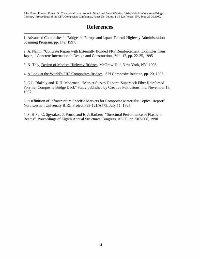
6. Bridge Installation The complete bridge was built by CPI at the LCCT in St. Louis, MO. It was transported on a flat bed truck the 90 miles to UMR. The Local Union #396 of the International Association of Bridge, Structural, Ornamental, and Reinforcing Ironworkers donated the crane used to install the bridge as well as the labor. In less than two hours the bridge was installed on July 29, 2000. Figure 12 shows the completed bridge. The bridge has integral fiber optic sensors that are continuously monitored via a web site.
John Unser, Prakash Kumar, K. Chandrashekhara, Antonio Nanni and Steve Watkins, “Adaptable All-Composite Bridge Concept,’ Proceedings of the CFA Composites Conference, Paper No. 39, pp. 1-15, Las Vegas, NV, Sept. 26-30,2000.
7
Conclusions Testing of the prototype deck sample indicates that the design of bridge deck using readily available, off-the-shelf pultruded glass and carbon FRP tubes can meet the necessary strength and deflection design criteria as laid down by AASHTO. The testing of quarter portion of the bridge deck in the laboratory provided valuable information to resolve certain manufacturing and design issues such as bonding between the tubes and number of layers of tubes to be used. Furthermore, the data measured during the testing provided baseline information by which to judge the bridge design and to compare later test data from the actual installed full-size bridge deck. Based on results of the present research and of extensive laboratory tests on FRP tubes and their assemblies, all-composite bridge decks made of pultruded glass and carbon tubes is judged to be a suitable replacement for bridges made of conventional materials. Although this is not the most efficient design for an all-composite bridge deck, it does represent a unique opportunity to implement composites in a vehicular bridge. It also offers an opportunity to study the durability of composite materials
Acknowledgements The project was funded by the National Science Foundation, Missouri Department of Transportation, University Transportation Center, and the Navy Center of Excellence for Composites Manufacturing Technology (CECMT) at the Lemay Center for Composites Technology (LCCT). CPI would like to acknowledge the following companies that donated materials to this project: Zoltek, St. Louis, MO (carbon for tubes and rods), Missouri Soybean Merchandising Council (funding the soybean-based resin for pultruded railing elements) Dow Chemicals (resin for carbon tubes), Fiber Glass Industries (fiberglass mat for carbon tubes), Albemarle Corporation (flame retardant for carbon tubes), Vetrotex America (fiberglass roving for glass tubes), Interplastic Corporation (vinyl ester resin for the glass tubes), Dexter (adhesive for bonding tubes), Luna Innovations, Inc. (suppliers of fiber optic strain instrumentation), The R.J. Marshall Company (recycled FRP), John Belk (Radio Frequency Identification Tags – RFID tags), and Boeing, St. Louis, MO (loan of RFID tag reader). CPI would like to thank the International Association of Bridge, Structural, Ornamental, and Reinforcing Ironworkers, Local Union #396, St. Louis, MO for the use of a crane and for providing labor for the installation of the bridge.
John Unser, Prakash Kumar, K. Chandrashekhara, Antonio Nanni and Steve Watkins, “Adaptable All-Composite Bridge Concept,’ Proceedings of the CFA Composites Conference, Paper No. 39, pp. 1-15, Las Vegas, NV, Sept. 26-30,2000.
8
Figure 1 - Example of FEA Model
Figure 2 - Schematic of Cross Section of Bridge
Symmetry in X
Symmetry in Y
John Unser, Prakash Kumar, K. Chandrashekhara, Antonio Nanni and Steve Watkins, “Adaptable All-Composite Bridge Concept,’ Proceedings of the CFA Composites Conference, Paper No. 39, pp. 1-15, Las Vegas, NV, Sept. 26-30,2000.
9
Figure 3 - Pultrusion Process for Carbon Tube
Figure 4 - Assembly of Bridge
John Unser, Prakash Kumar, K. Chandrashekhara, Antonio Nanni and Steve Watkins, “Adaptable All-Composite Bridge Concept,’ Proceedings of the CFA Composites Conference, Paper No. 39, pp. 1-15, Las Vegas, NV, Sept. 26-30,2000.
10
Figure 5 – Close-up of Railings
Figure 6 - Single Tube Test Set-up
John Unser, Prakash Kumar, K. Chandrashekhara, Antonio Nanni and Steve Watkins, “Adaptable All-Composite Bridge Concept,’ Proceedings of the CFA Composites Conference, Paper No. 39, pp. 1-15, Las Vegas, NV, Sept. 26-30,2000.
11
Figure 7 - Double Tube Test Set-up
Figure 8 - Four Layer Test Set-up
John Unser, Prakash Kumar, K. Chandrashekhara, Antonio Nanni and Steve Watkins, “Adaptable All-Composite Bridge Concept,’ Proceedings of the CFA Composites Conference, Paper No. 39, pp. 1-15, Las Vegas, NV, Sept. 26-30,2000.
12
Figure 9 - Photograph of Single Tube Failure
Figure 10 - Photograph of Failure of Double Tube Assembly
John Unser, Prakash Kumar, K. Chandrashekhara, Antonio Nanni and Steve Watkins, “Adaptable All-Composite Bridge Concept,’ Proceedings of the CFA Composites Conference, Paper No. 39, pp. 1-15, Las Vegas, NV, Sept. 26-30,2000.
13
Figure 11 - Photograph of Four Layer Failure
Figure 12 - Photograph of Bridge at UMR Taken With Web Camera
John Unser, Prakash Kumar, K. Chandrashekhara, Antonio Nanni and Steve Watkins, “Adaptable All-Composite Bridge Concept,’ Proceedings of the CFA Composites Conference, Paper No. 39, pp. 1-15, Las Vegas, NV, Sept. 26-30,2000.
14
References 1. Advanced Composites in Bridges in Europe and Japan, Federal Highway Administration Scanning Program, pp. 142, 1997. 2. A. Nanni, “Concrete Repair with Externally Bonded FRP Reinforcement: Examples from Japan,’’ Concrete International: Design and Construction,, Vol. 17, pp. 22-25, 1995 3. N. Taly, Design of Modern Highway Bridges, McGraw-Hill, New York, NY, 1998. 4. A Look at the World’s FRP Composites Bridges, SPI Composite Institute, pp. 20, 1998. 5. G.L. Blakely and R.H. Moorman, “Market Survey Report: Superdeck Fiber Reinforced Polymer Composite Bridge Deck” Study published by Creative Pultrusions, Inc. November 13, 1997. 6. “Definition of Infrastructure Specific Markets for Composite Materials: Topical Report” Northwestern University BIRL Project P93-121/A573, July 11, 1995. 7. S. H Fu, C. Spyrakos, J. Prucz, and E. J. Barbero “Structural Performance of Plastic I-Beams”, Proceedings of Eighth Annual Structures Congress, ASCE, pp. 507-508, 1990