activity: infiltration trenches gip 04 - nashville · activity: infiltration trenches gip ......
TRANSCRIPT
General Application
Activity: Infiltration Trenches GIP‐04
Volume 5 – Green Infrastructure Practices February 2016 1
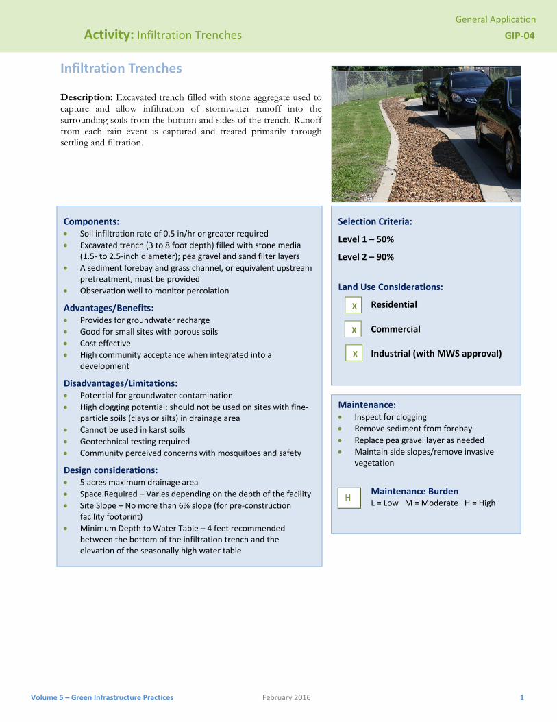
Infiltration Trenches Description: Excavated trench filled with stone aggregate used to capture and allow infiltration of stormwater runoff into the surrounding soils from the bottom and sides of the trench. Runoff from each rain event is captured and treated primarily through settling and filtration.
Components: Soil infiltration rate of 0.5 in/hr or greater required
Excavated trench (3 to 8 foot depth) filled with stone media (1.5‐ to 2.5‐inch diameter); pea gravel and sand filter layers
A sediment forebay and grass channel, or equivalent upstream pretreatment, must be provided
Observation well to monitor percolation
Advantages/Benefits: Provides for groundwater recharge
Good for small sites with porous soils
Cost effective
High community acceptance when integrated into a development
Disadvantages/Limitations: Potential for groundwater contamination
High clogging potential; should not be used on sites with fine‐particle soils (clays or silts) in drainage area
Cannot be used in karst soils
Geotechnical testing required
Community perceived concerns with mosquitoes and safety
Design considerations: 5 acres maximum drainage area
Space Required – Varies depending on the depth of the facility
Site Slope – No more than 6% slope (for pre‐construction facility footprint)
Minimum Depth to Water Table – 4 feet recommended between the bottom of the infiltration trench and the elevation of the seasonally high water table
Selection Criteria:
Level 1 – 50%
Level 2 – 90%
Land Use Considerations:
Residential Commercial Industrial (with MWS approval)
Maintenance: Inspect for clogging
Remove sediment from forebay
Replace pea gravel layer as needed
Maintain side slopes/remove invasive vegetation
Maintenance Burden L = Low M = Moderate H = High
H
X
X
X
General Application
Activity: Infiltration Trenches GIP‐04
Volume 5 – Green Infrastructure Practices February 2016 2
SECTION 1: DESCRIPTION
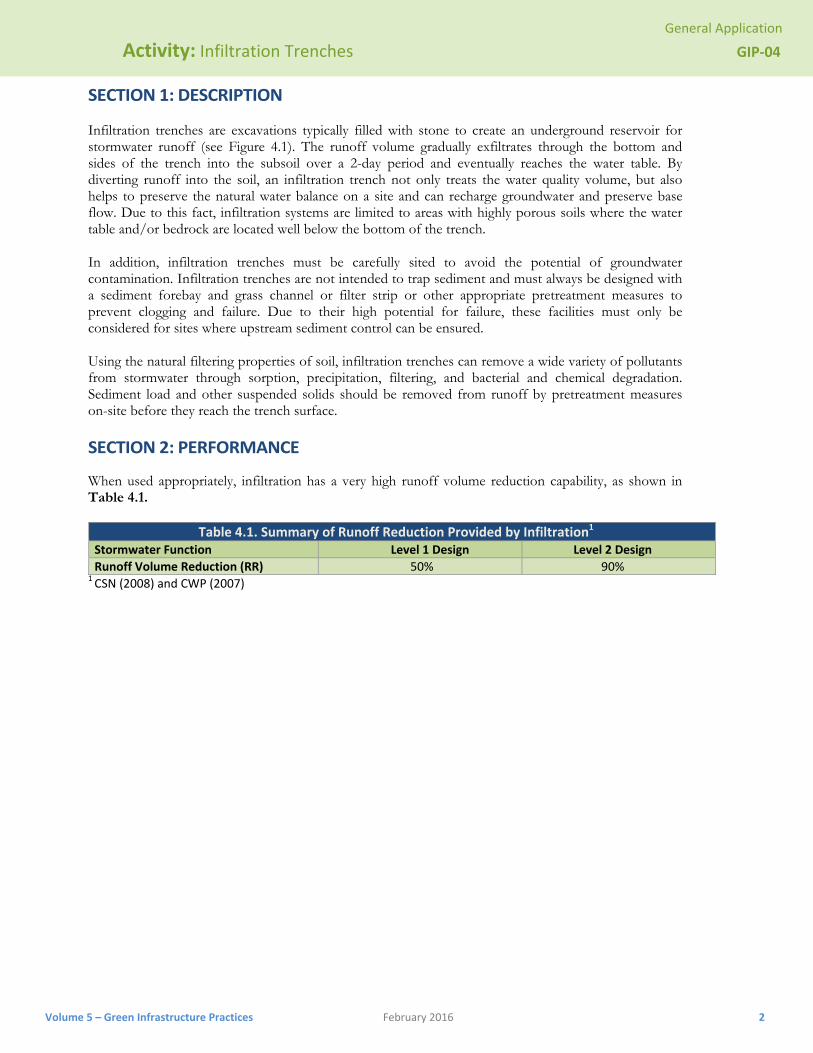
Infiltration trenches are excavations typically filled with stone to create an underground reservoir for stormwater runoff (see Figure 4.1). The runoff volume gradually exfiltrates through the bottom and sides of the trench into the subsoil over a 2-day period and eventually reaches the water table. By diverting runoff into the soil, an infiltration trench not only treats the water quality volume, but also helps to preserve the natural water balance on a site and can recharge groundwater and preserve base flow. Due to this fact, infiltration systems are limited to areas with highly porous soils where the water table and/or bedrock are located well below the bottom of the trench.
In addition, infiltration trenches must be carefully sited to avoid the potential of groundwater contamination. Infiltration trenches are not intended to trap sediment and must always be designed with a sediment forebay and grass channel or filter strip or other appropriate pretreatment measures to prevent clogging and failure. Due to their high potential for failure, these facilities must only be considered for sites where upstream sediment control can be ensured.
Using the natural filtering properties of soil, infiltration trenches can remove a wide variety of pollutants from stormwater through sorption, precipitation, filtering, and bacterial and chemical degradation. Sediment load and other suspended solids should be removed from runoff by pretreatment measures on-site before they reach the trench surface.
SECTION 2: PERFORMANCE
When used appropriately, infiltration has a very high runoff volume reduction capability, as shown in Table 4.1.
Table 4.1. Summary of Runoff Reduction Provided by Infiltration1
Stormwater Function Level 1 Design Level 2 Design
Runoff Volume Reduction (RR) 50% 90% 1 CSN (2008) and CWP (2007)
Volum
Act
me 5 – Green Infr
SECTION 3
ivity: Infil
rastructure Prac
3: TYPICAL
Figure 4.
tration Tre
ctices
L DETAILS
.1. Infiltratio
enches
on Trench Pl
February 2016
lan and Sect
ction (VADEQ
Q, 2013)
Gen
neral Applicat
GIP
3
tion
‐04
3
Volum
Act
me 5 – Green Infr
ivity: Infil
rastructure Prac
Figu
Fig
tration Tre
ctices
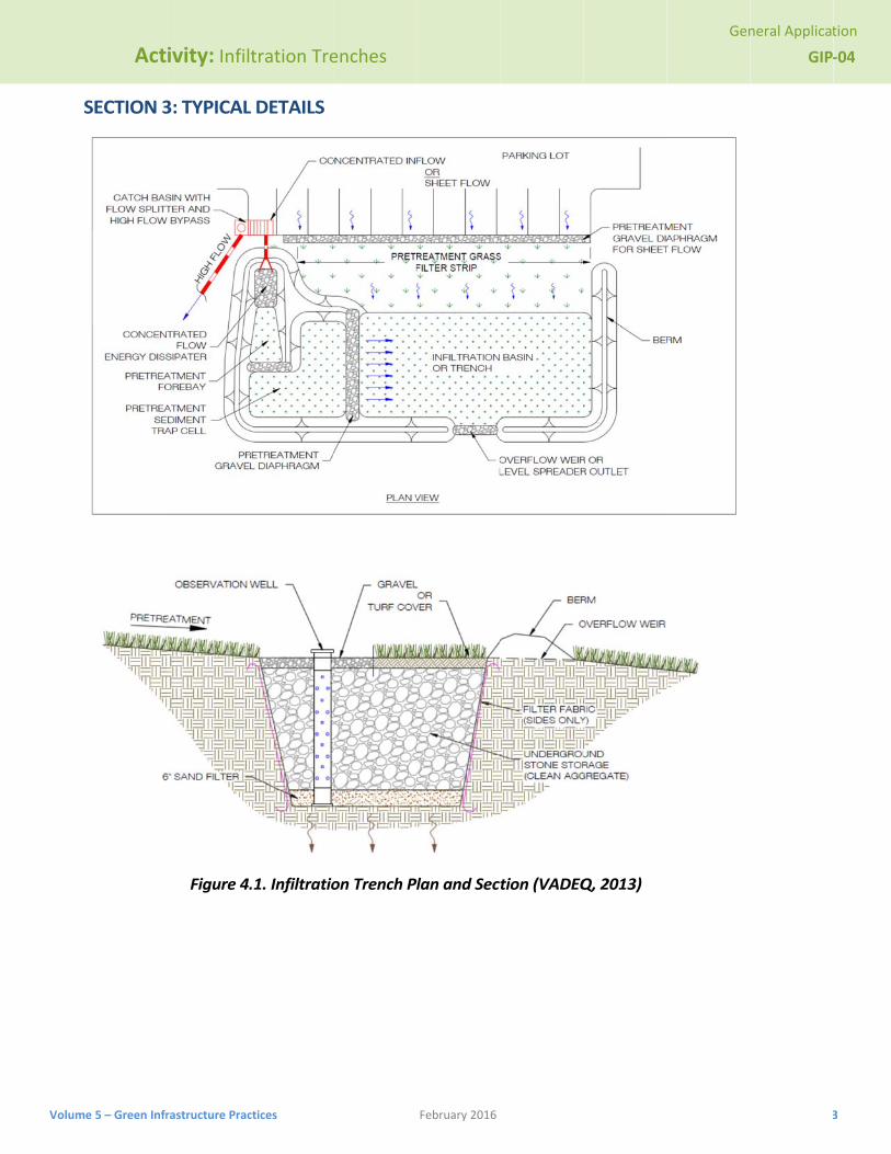
ure 4.2: Typi
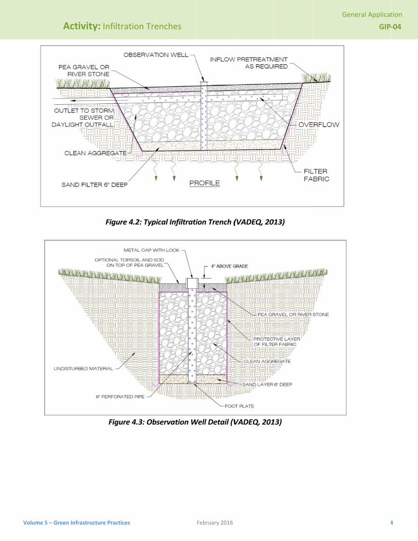
gure 4.3: Ob
enches
ical Infiltrat
servation W
February 2016
tion Trench (
Well Detail (V
(VADEQ, 20
VADEQ, 201
013)
13)
Gen
neral Applicat
GIP
4
tion
‐04
4

General Application
Activity: Infiltration Trenches GIP‐04
Volume 5 – Green Infrastructure Practices February 2016 5
SECTION 4: DESIGN CRITERIA 4.1 Overview
Infiltration trenches are generally suited for medium-to-high density residential, commercial and institutional developments where the subsoil is sufficiently permeable to provide a reasonable infiltration rate and the water table is low enough to prevent groundwater contamination. They are applicable primarily for impervious areas where there are not high levels of fine particulates (clay/silt soils) in the runoff and should only be considered for sites where the sediment load is relatively low.
Infiltration trenches can either be used to capture sheet flow from a drainage area or function as an off-line device. Due to the relatively narrow shape, infiltration trenches can be adapted to many different types of sites and can be utilized in retrofit situations. Unlike some other structural stormwater controls, they can easily fit into the margin, perimeter, or other unused areas of developed sites.
To protect groundwater from potential contamination, runoff from designated hotspot land uses or activities must not be infiltrated. Infiltration trenches should not be used for manufacturing and industrial yards, where there is a potential for high concentrations of soluble pollutants and heavy metals. In addition, infiltration should not be considered for areas with a high pesticide concentration. Infiltration trenches are also not suitable in areas with karst geology without adequate geotechnical testing by qualified individuals and in accordance with Appendix 4-A.
To be suitable for infiltration, underlying soils should have an infiltration rate of greater than 0.5 inches per hour, as initially determined from NRCS soil textural classification and subsequently confirmed by field geotechnical tests. The minimum geotechnical testing is one test hole per 50 linear feet, with a minimum of two borings per facility (taken within the proposed limits of the facility). Infiltration trenches cannot be used in fill soils.
Infiltration trenches should have a contributing drainage area of 2 acres or less and be as close to 100% impervious as possible.
Unless slope stability calculations demonstrate otherwise, infiltration practices should be located a minimum horizontal distance of 200 feet from down-gradient slopes greater than 20%. The average slope of the contributing drainage areas should be less than 15%.
Soils in the drainage area tributary to an infiltration trench should have a clay content of less than 20% and a silt/clay content of less than 40% to prevent clogging and failure.
There should be at least 2 feet between the bottom of the infiltration trench and the elevation of the seasonally high water table.
Clay lenses, bedrock or other restrictive layers below the bottom of the trench will reduce infiltration rates unless excavated.
Suggested minimum setback requirements for infiltration trench facilities: o From a property line – 10 feet o From a building foundation – 25 feet o From a private well – 100 feet o From a public water supply well – 1,200 feet o From a septic system tank/leach field – 100 feet o From surface waters – 100 feet o From surface drinking water sources – 400 feet (100 feet for a tributary)
When used in an off-line configuration, the storage volume (Tv) is diverted to the infiltration trench through the use of a flow splitter. Stormwater flows greater than the Tv are diverted to other controls or downstream using a diversion structure or flow splitter.
To reduce the potential for costly maintenance and/or system reconstruction, it is strongly recommended that the trench be located in an open or lawn area, with the top of the structure as close to the ground surface as possible. Infiltration trenches shall not be located beneath paved
General Application
Activity: Infiltration Trenches GIP‐04
Volume 5 – Green Infrastructure Practices February 2016 6
surfaces, such as parking lots. Infiltration trenches are designed for intermittent flow and must be allowed to drain and allow
aeration of the surrounding soil between rainfall events. They must not be used on sites with a continuous flow from groundwater, sump pumps, or other sources.
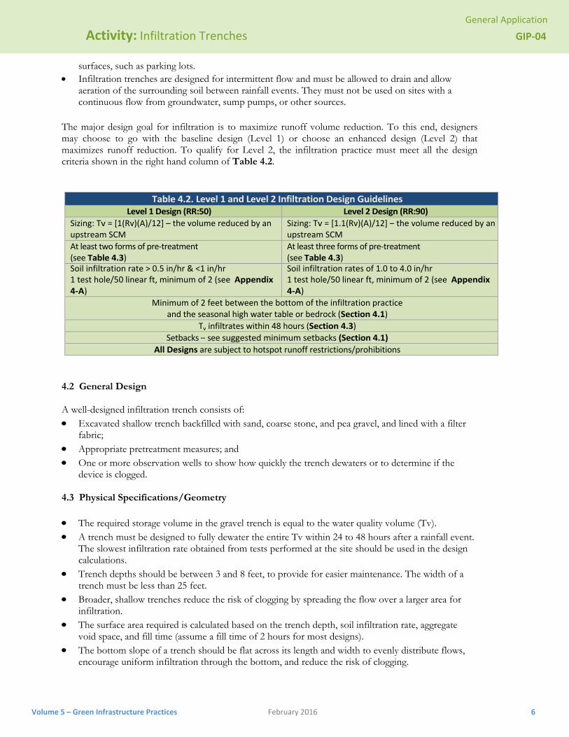
The major design goal for infiltration is to maximize runoff volume reduction. To this end, designers may choose to go with the baseline design (Level 1) or choose an enhanced design (Level 2) that maximizes runoff reduction. To qualify for Level 2, the infiltration practice must meet all the design criteria shown in the right hand column of Table 4.2.
Table 4.2. Level 1 and Level 2 Infiltration Design Guidelines
Level 1 Design (RR:50) Level 2 Design (RR:90)
Sizing: Tv = [1(Rv)(A)/12] – the volume reduced by an upstream SCM
Sizing: Tv = [1.1(Rv)(A)/12] – the volume reduced by an upstream SCM
At least two forms of pre‐treatment (see Table 4.3)
At least three forms of pre‐treatment (see Table 4.3)
Soil infiltration rate > 0.5 in/hr & <1 in/hr 1 test hole/50 linear ft, minimum of 2 (see Appendix 4‐A)
Soil infiltration rates of 1.0 to 4.0 in/hr 1 test hole/50 linear ft, minimum of 2 (see Appendix 4‐A)
Minimum of 2 feet between the bottom of the infiltration practice and the seasonal high water table or bedrock (Section 4.1)
Tv infiltrates within 48 hours (Section 4.3)
Setbacks – see suggested minimum setbacks (Section 4.1)
All Designs are subject to hotspot runoff restrictions/prohibitions
4.2 General Design
A well-designed infiltration trench consists of: Excavated shallow trench backfilled with sand, coarse stone, and pea gravel, and lined with a filter
fabric; Appropriate pretreatment measures; and One or more observation wells to show how quickly the trench dewaters or to determine if the
device is clogged.
4.3 Physical Specifications/Geometry
The required storage volume in the gravel trench is equal to the water quality volume (Tv). A trench must be designed to fully dewater the entire Tv within 24 to 48 hours after a rainfall event.
The slowest infiltration rate obtained from tests performed at the site should be used in the design calculations.
Trench depths should be between 3 and 8 feet, to provide for easier maintenance. The width of a trench must be less than 25 feet.
Broader, shallow trenches reduce the risk of clogging by spreading the flow over a larger area for infiltration.
The surface area required is calculated based on the trench depth, soil infiltration rate, aggregate void space, and fill time (assume a fill time of 2 hours for most designs).
The bottom slope of a trench should be flat across its length and width to evenly distribute flows, encourage uniform infiltration through the bottom, and reduce the risk of clogging.
General Application
Activity: Infiltration Trenches GIP‐04
Volume 5 – Green Infrastructure Practices February 2016 7
The stone aggregate used in the trench should be washed, bank-run gravel, 1.5 to 2.5 inches in diameter with a porosity of about 40%. Aggregate contaminated with soil shall not be used. A porosity value (pore volume/total volume) of 0.32 should be used in calculations, unless aggregate specific data exist.
A 6-inch layer of clean, washed sand is placed on the bottom of the trench to encourage drainage and prevent compaction of the native soil while the stone aggregate is added.
The infiltration trench is lined on the sides and top by an appropriate geotextile filter fabric that prevents soil piping but has greater permeability than the parent soil. The top layer of filter fabric is located 2 to 6 inches from the top of the trench and serves to prevent sediment from passing into the stone aggregate. Since this top layer serves as a sediment barrier, it will need to be replaced more frequently and must be readily separated from the side sections.
The top surface of the infiltration trench above the filter fabric is typically covered with pea gravel. The pea gravel layer improves sediment filtering and maximizes the pollutant removal in the top of the trench. In addition, it can easily be removed and replaced should the device begin to clog. Alternatively, the trench can be covered with permeable topsoil and planted with grass in a landscaped area.
An observation well must be installed in every infiltration trench and should consist of a perforated PVC or HDPE pipe, 4 to 6 inches in diameter, extending to the bottom of the trench (see Figure 4.3 for a schematic of an observation well). The observation well will show the rate of dewatering after a storm, as well as provide a means of determining sediment levels at the bottom and when the filter fabric at the top is clogged and maintenance is needed. It should be installed along the centerline of the structure, flush with the ground elevation of the trench. A visible floating marker should be provided to indicate the water level. The top of the well should be capped and locked to discourage vandalism and tampering.
The trench excavation should be limited to the width and depth specified in the design. Excavated material should be placed away from the open trench so as not to jeopardize the stability of the trench sidewalls. The bottom of the excavated trench shall not be loaded in a way that causes soil compaction, and should be scarified prior to placement of sand. The sides of the trench shall be trimmed of all large roots. The sidewalls shall be uniform with no voids and scarified prior to backfilling. All infiltration trench facilities should be protected during site construction and should be constructed after upstream areas have been stabilized.
4.4 Pretreatment/Inlets
Pretreatment facilities must always be used in conjunction with an infiltration trench to prevent clogging and failure
For a trench receiving sheet flow from an adjacent drainage area, the pretreatment system should consist of a vegetated filter strip with a minimum 25-foot length. A vegetated buffer strip around the entire trench is required if the facility is receiving runoff from both directions. If the infiltration rate for the underlying soils is greater than 2 inches per hour, 50% of the Tv should be pretreated by another method prior to reaching the infiltration trench.
For an off-line configuration, pretreatment should consist of a sediment forebay, vault, plunge pool, or similar sedimentation chamber (with energy dissipaters) sized to 25% of the storage volume (Tv). Exit velocities from the pretreatment chamber must be nonerosive for the 2-year design storm.
Every infiltration practice must include multiple pretreatment techniques, although the nature of pretreatment practices depends on the scale at which infiltration is applied. The number, volume and type of acceptable pretreatment techniques needed for the two scales of infiltration are provided in Table 4.3.
General Application
Activity: Infiltration Trenches GIP‐04
Volume 5 – Green Infrastructure Practices February 2016 8
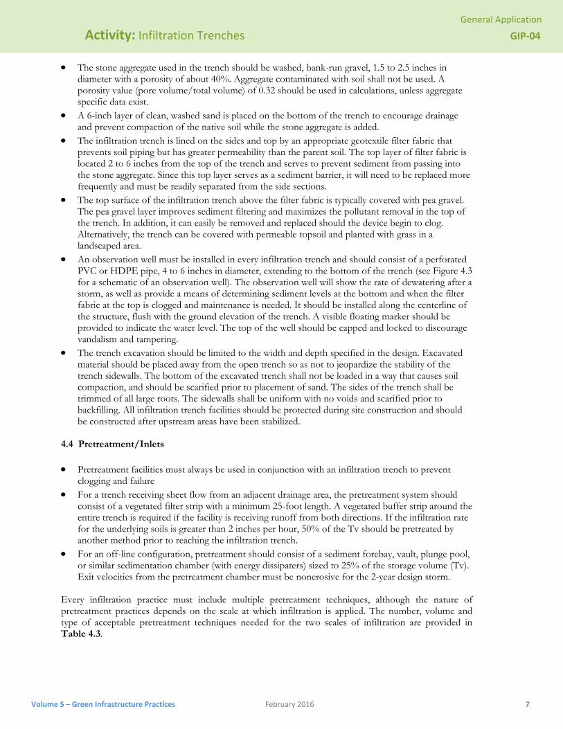
Table 4.3. Required Pretreatment Elements for Infiltration Practices Pretreatment1 Scale of Infiltration
Small‐Scale Infiltration Conventional Infiltration
Number and Volume of Pretreatment Techniques Employed
2 techniques; 15% minimum pretreatment volume required (inclusive).
3 techniques; 25%minimum pretreatment volume required (inclusive); at least one separate pre‐treatment cell.
Acceptable Pretreatment Techniques
Grass filter strip Grass channel Plunge pool Gravel diaphragm
Sediment trap cell Sand filter cell Sump pit Grass filter strip Gravel diaphragm
1 A minimum of 50% of the runoff reduction volume must be pre‐treated by a filtering or bioretention practice prior to infiltration if the site is a restricted stormwater hotspot 4.5 Infiltration Material Specifications The basic material specifications for infiltration practices are outlined in Table 4.4 below:
Table 4.4. Infiltration Material Specifications Material Specification Notes
Stone Clean, aggregate with a maximum diameter of 3.5 inches and a minimum diameter of 1.5 inches (VDOT No. 1 Open‐Graded Coarse Aggregate) or the equivalent.
Observation Well Install a vertical 6‐inch Schedule 40 PVC perforated pipe, with a lockable screw cap and anchor plate.
Install one per 50 feet of length of infiltration the practice.
Trench Bottom Install a 6‐ to 8‐inch sand layer (VDOT Fine Aggregate, Grade A or B)
Trench Surface Cover Install a 3‐inch layer of river stone or pea gravel. Turf is acceptable when there is subsurface inflow (e.g., a roof leader).
This provides an attractive surface cover that can suppress weed growth.
Buffer Vegetation Keep adjacent vegetation from forming an overhead canopy above infiltration practices, in order to keep leaf litter, fruits and other vegetative material from clogging the stone.
Filter Fabric (sides only)
Use non‐woven polyprene geotextile with a flow rate of > 110 gallons/min./sq. ft. (e.g., Geotex 351 or equivalent).
Choking Layer Install a 2‐ to 4‐inch layer of choker stone (typically #8 or # 89 washed gravel) over the underdrain stone.
Overflow Collection Pipe (where needed)
Use 6‐inch rigid schedule 40 PVC pipe, with 3/8” perforations at 6 inches on center, with each perforated underdrain, installed at a slope of 1% for the length of the infiltration practice.
Install non‐perforated pipe with one or more caps, as needed.
Stone Jacket for Underdrain
The stone should be double‐washed and clean and free of all soil fines.
Install a minimum of 3 inches of #57 stone above the underdrain and a minimum of 12 inches below it.
General Application
Activity: Infiltration Trenches GIP‐04
Volume 5 – Green Infrastructure Practices February 2016 9
4.6 Other Design Criteria
Outlet Structures. Outlet structures are not required for infiltration trenches. Emergency Spillway. Typically for off-line designs, there is no need for an emergency spillway.
However, a nonerosive overflow channel should be provided to safely pass flows that exceed the storage capacity of the trench to a stabilized downstream area or watercourse.
Maintenance Access. Adequate access in an easement should be provided to an infiltration trench facility for inspection and maintenance.
Safety Features. In general, infiltration trenches are not likely to pose a physical threat to the public and do not need to be fenced.
Landscaping. Vegetated filter strips and buffers should fit into and blend with surrounding area. Native grasses are preferable, if compatible. The trench may be covered with permeable topsoil and planted with grass in a landscaped area.
Additional Site-Specific Design Criteria and Issues. Not suitable for karst areas without adequate geotechnical testing.
Additional Permitting Requirements. Underground Injection Control Permit (UIC) may be required from the State of Tennessee if the trench is deeper than its widest surface dimension.
General Application
Activity: Infiltration Trenches GIP‐04
Volume 5 – Green Infrastructure Practices February 2016 10
SECTION 5: DESIGN PROCEDURES
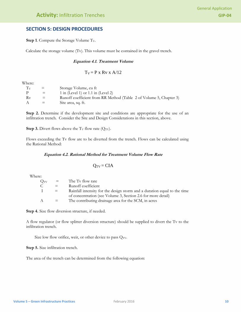
Step 1. Compute the Storage Volume TV.
Calculate the storage volume (Tv). This volume must be contained in the gravel trench.
Equation 4.1. Treatment Volume
TV = P x Rv x A/12
Where: TV = Storage Volume, cu ft P = 1 in (Level 1) or 1.1 in (Level 2) Rv = Runoff coefficient from RR Method (Table 2 of Volume 5, Chapter 3) A = Site area, sq. ft.
Step 2. Determine if the development site and conditions are appropriate for the use of an infiltration trench. Consider the Site and Design Considerations in this section, above.
Step 3. Divert flows above the TV flow rate (QTV).
Flows exceeding the Tv flow are to be diverted from the trench. Flows can be calculated using the Rational Method:
Equation 4.2. Rational Method for Treatment Volume Flow Rate
QTV = CIA
Where: QTV = The Tv flow rate C = Runoff coefficient
I = Rainfall intensity for the design storm and a duration equal to the time of concentration (see Volume 3, Section 2.6 for more detail)
A = The contributing drainage area for the SCM, in acres
Step 4. Size flow diversion structure, if needed.
A flow regulator (or flow splitter diversion structure) should be supplied to divert the Tv to the infiltration trench.
Size low flow orifice, weir, or other device to pass QTV.
Step 5. Size infiltration trench.
The area of the trench can be determined from the following equation:

General Application
Activity: Infiltration Trenches GIP‐04
Volume 5 – Green Infrastructure Practices February 2016 11
Equation 4.3. Surface Area for Infiltration Trench
SAT
0.4 D
Where: SA = Surface Area (sq. ft.) Tv = Total volume to be infiltrated (cu. ft.) D = Media depth of trench in feet.
All infiltration systems should be designed to fully dewater the entire Tv within 24 to 48 hours after the rainfall event.
See the Physical Specifications/Geometry section of Site and Design Considerations for more details.
Step 6. Determine pretreatment volume and design pretreatment measures.
Size pretreatment facility to treat 25% of the water quality volume (Tv) for offline configurations.
See the Pretreatment / Inlets (Section 4.3) for more details.
Step 7. Design spillway(s).
Adequate stormwater outfalls should be provided for the overflow exceeding the capacity of the trench, ensuring nonerosive velocities on the down-slope.
SECTION 6: SPECIAL CASE DESIGN ADAPTATIONS 6.1 Karst Terrain
Conventional infiltration practices should not be used in karst regions due to concerns about sinkhole formation and groundwater contamination. Small-scale infiltration areas are permissible only if geotechnical studies indicate there is at least 4 feet of vertical separation between the bottom of the infiltration facilities and the underlying karst layer AND an impermeable liner and underdrain are used. In many cases, bioretention is a preferred stormwater management alternative to infiltration in karst areas.
SECTION 7: AS‐BUILT CERTIFICATION CONSIDERATIONS
After the infiltration trench has been constructed, an as-built certification must be performed by a registered Professional Engineer and submitted to Metro. The as-built certification verifies that the SCM was installed as designed and approved.
The following components must be addressed in the as-built certification:
The infiltration trench cannot be located in a sinkhole area or in karst soils. Infiltration rates must be verified. Proper dimensions for the trench must be verified. A mechanism for overflow for large storm events must be provided.

General Application
Activity: Infiltration Trenches GIP‐04
Volume 5 – Green Infrastructure Practices February 2016 12
SECTION 8: MAINTENANCE
Each SCM must have a Maintenance Document submitted to Metro for approval and maintained and updated by the SCM owner. Refer to Volume 1, Appendix C for information about the Maintenance Document for infiltration trenches, as well as an inspection checklist. The Maintenance Document must be completed and submitted to Metro with grading permit application. The Maintenance Document is for the use of the SCM owner in performing routine inspections. The developer/owner is responsible for the cost of maintenance and annual inspections. The SCM owner must maintain and update the SCM operations and maintenance plan. At a minimum, the operations and maintenance plan must address: Ensure that contributing area, facility and inlets are clear of debris. Ensure that the contributing area is stabilized. Remove sediment and oil/grease from pretreatment devices, as well as overflow structures. Check observation wells following 3 days of dry weather. Failure to percolate within this time period
indicates clogging. Inspect pretreatment devices and diversion structures for sediment build-up and structural damage. Remove trees that start to grow in the vicinity of the trench. Replace pea gravel/topsoil and top surface filter fabric (when clogged). Perform total rehabilitation of the trench to maintain design storage capacity. Excavate trench walls to expose clean soil.
SECTION 9: REFERENCES
Chesapeake Stormwater Network (CSN). 2008. Technical Bulletin 1: Stormwater Design Guidelines for Karst Terrain in the Chesapeake Bay Watershed. Version 1.0. Baltimore, MD. Available online at: http://www.chesapeakestormwater.net/all-things-stormwater/stormwater-guidance-for-karst-terrain-in-the-chesapeake-bay.html
CWP. 2007. National Pollutant Removal Performance Database, Version 3.0. Center for Watershed Protection, Ellicott City, MD.
ARC, 2001. Georgia Stormwater Management Manual Volume 2 Technical Handbook.
CDM, 2000. Metropolitan Nashville and Davidson County Stormwater Management Manual Volume 4 Best Management Practices.
Federal Highway Administration (FHWA), United States Department of Transportation. Stormwater Best Management Practices in an Ultra-Urban Setting: Selection and Monitoring. Accessed January 2006. http://www.fhwa.dot.gov/environment/ultraurb/index.htm.
VADCR. 2011. Stormwater Design Specification No. 8: Infiltration, Version 1.9. Virginia Department of Conservation and Recreation.
VADEQ. 2013. Stormwater Design Specification No. 8: Infiltration, Version 2.0. Virginia Department of Environmental Quality.
General Application
Activity: Infiltration Trenches GIP‐04
Volume 5 – Green Infrastructure Practices February 2016 13
APPENDIX 4‐A
INFILTRATION SOIL TESTING PROCEDURES
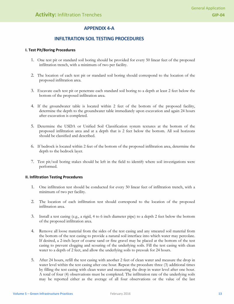
I. Test Pit/Boring Procedures
1. One test pit or standard soil boring should be provided for every 50 linear feet of the proposed infiltration trench, with a minimum of two per facility.
2. The location of each test pit or standard soil boring should correspond to the location of the proposed infiltration area.
3. Excavate each test pit or penetrate each standard soil boring to a depth at least 2 feet below the bottom of the proposed infiltration area.
4. If the groundwater table is located within 2 feet of the bottom of the proposed facility, determine the depth to the groundwater table immediately upon excavation and again 24 hours after excavation is completed.
5. Determine the USDA or Unified Soil Classification system textures at the bottom of the proposed infiltration area and at a depth that is 2 feet below the bottom. All soil horizons should be classified and described.
6. If bedrock is located within 2 feet of the bottom of the proposed infiltration area, determine the depth to the bedrock layer.
7. Test pit/soil boring stakes should be left in the field to identify where soil investigations were performed.
II. Infiltration Testing Procedures
1. One infiltration test should be conducted for every 50 linear feet of infiltration trench, with a minimum of two per facility.
2. The location of each infiltration test should correspond to the location of the proposed infiltration area.
3. Install a test casing (e.g., a rigid, 4 to 6 inch diameter pipe) to a depth 2 feet below the bottom of the proposed infiltration area.
4. Remove all loose material from the sides of the test casing and any smeared soil material from the bottom of the test casing to provide a natural soil interface into which water may percolate. If desired, a 2-inch layer of coarse sand or fine gravel may be placed at the bottom of the test casing to prevent clogging and scouring of the underlying soils. Fill the test casing with clean water to a depth of 2 feet, and allow the underlying soils to presoak for 24 hours.
5. After 24 hours, refill the test casing with another 2 feet of clean water and measure the drop in water level within the test casing after one hour. Repeat the procedure three (3) additional times by filling the test casing with clean water and measuring the drop in water level after one hour. A total of four (4) observations must be completed. The infiltration rate of the underlying soils may be reported either as the average of all four observations or the value of the last

General Application
Activity: Infiltration Trenches GIP‐04
Volume 5 – Green Infrastructure Practices February 2016 14
observation. The infiltration rate should be reported in terms of inches per hour.
6. Infiltration testing may be performed within an open test pit or a standard soil boring. After infiltration testing is completed, the test casing should be removed and the test pit or soil boring should be backfilled and restored.