active control technology experience with the space ... · active control technology experience...
TRANSCRIPT
3 1176 01328 5623
N.ASA Technical Memorandum 85910NASA-TM-85910 19850001764
r1
Active Control Technology ExperienceWith the Space Shuttle in the LandingRegimeBruce G. Powers
October 1984
NI\S/\National Aeronautics andSpace Administration
LIBRARY COpy
lAJlIGLEY RESEARCH C"'\ITERl.IBRARY, NASA
MAMelON, VIRGINIA
https://ntrs.nasa.gov/search.jsp?R=19850001764 2018-07-16T12:13:39+00:00Z

"
..

::-r:.IT~~! :!.-!~!L-i"'.· .
A
•DI SPLA\! 1SL/5../ 1
85NI0071** ISSUE 1 PAGE 12 CATEGORY 8 RPT~: NASA-TM-8531G H-1250NAS 1.15~85310 84/18/00 12 PAGES UNCLASSIFIED DOCUMENT
UTTL= Active control technology experience wjth the Space Shuttle in the landing
Nat10nal Aeronautlcs and Space Adm1n1strat1onc Ames Research Center,Moffett Field~ CaJ~f= AVAIL=NTIS SAP: He AG2/MF AOlPresented at the AGARD Flight Meche Panel SYillP= on ActIve Control Systems,TOronto1 15-18 Oct. 1984
MAJS: /*ACTIVE CONTROL/*FLIGHT CHARACTERISTICS/*FLIGHT SIMULATION;*SPACE~tlll..,..-ri r-r-... .:-..:.l"'"""n ....... ~-.r-r-Mf'.r--r ! J'o••• lt"""-.Tca_t ..-
::JHU ; i Lt.:=i.l .'-. ~r·H~_-t.C-r:::H;- f LHP.1LJ 1. i\Jt~
MINS: / DESIGN ANALYSIS; FLIGHT CONTROL/ FLIGHT TESTS; FLY BY WIRE CONTROL!OSCILLATIONS/ PILOT PERFORMANCE/ TIME
ABA:

c·
NASA Technical Memorandum 85910
Active Control Technology ExperienceWith the Space Shuttle in the LandingRegimeBruce G. PowersNASA Ames Research Center, Dryden Flight ResearchFacility, Edwards, California 93523
1984
NI\S/\National Aeronautics andSpace AdministrationAmes Research CenterDryden Flight Research FacilityEdwards, California 93523


(,
16-1
ACTIVE CONTROL TECHNOLOGY EX~ERIENCE.
WITH THE SPACE SHUTTLE IN THE LANDING REGIME
Bruce G. ·PowersNASA Ames Research Center
Dryden Flight Research FacilityEdwards, California 93523
U.S.A.
SUMMARY
The shuttle program took on the cha,llenge of providing a manual landing capability for an operationalvehicle returning ·from orbit. Some complex challenges were encountered in developing the longitudinalflying qualities required to land the orbiter manually in an operational environment. Approach. and landing test flights indicated a tendency for pilot-induced oscillation near landing. Changes in the opera~
tiona1 procedures reduced the difficulty of the landing task, and an adaptive stick filter was incorporated to reduce the severity of any pilot~induced oscillatory motions. Fixed-base, moving-base, andin-flight simulations were used for the evaluations, and in general, flight simulation has .been the onlyreliable means of assessing the, low-speed longitudinal flying qualities problems. Overall, the orbitercontrol system and operational procedures have produced a good capability for routinely performing precise landings in a large, unpowere'd vehicle.with a, low lift-to-drag ratio.
SYMBOLS
ALT
DFBW
FSAA
LID
approach and landing tests
digital fly-by-wire
flight simulator for advanced aircraft
lift-to-drag
Pro
TAEM
TIFS
VMS
pilot-induced oscillation
terminal area energy management
total in-flight simulator
vertical motion simulator
1.0 INTRODUCTION
The sl:iuttle program took 'on the cl:iallenge. of providing a manual landing capability for an operational vehicle returning from orbit. This required the development of longitudinal flying qualitie~suitable for the landing of the unpowered, low lift-to-drag (LID) orbiter in an operational environment.A vehicle with an operational capability to land during the day or night in all types of weather usinga 4570-m.( 15, OOO-ft) runway was required for the mission. The control system design was complicatedby the requirement for.a center-of-gravity position that ranged from statically stable to staticallyunstable. At .the time the orbiter was designed, the flying qualities data base was limited" for aircraftwith advanced control systems. similar to that required to meet the orbiter design requirements. Limitedexperience existed in the use of high-gain, digital flight control systems for statically unstable aircraft, and the influence of the time delay between the pilot input and the airplane response would notbe fully appreciated until much later, after experience with the orbiter and highly augmented fighteraircraft. In general, the flying qualities design criteria' reflected experience with more conventionalairplanes that only required. very ,simple control systems. The space shuttle vehicle design reflected theoptimistic views of the benefits of active control technology and digital control that were expressed inthe 1973 and 1974 active control technology conferences.
Before the orbital flights of the space shuttle, five flights were made to evaluate the low-speedcharacteristics during the approach and landing (ALT) tests. The orbiter was launched from a modifiedB-747, and the flight regime from 6100 m (20,000 ft) to touchdown was investigated. The fifth landingwas on the 4570-m (15,000-ft) concrete runway and tendencies for pilot-induced oscillations (PIO) inboth pitch and roll were exhibited near touchdown. In 1978, after the ALT experience, a simulation program was conducted to study the cause and significance of the. PIO characteristics observed in flight.The NASA Ames Researcl:i'Center's flight simulator for advanced aircraft (FS~) moving-base simUlation andthe Calspan total in-flight simulator .(TIFS) facility were used. Following these simulations, controlsystem improvements were developed and evaluated on a ground~based simulator using a tracking task toevaluate the PIO characteristics. One of these systems wa.s an adaptive .stick gain (RefEl. 1 and 2) whichwas designed to reduce the severity of the PIO tendencies by providing a closed-loop bandwidth limiterto prevent. the pilot from reaching control surface rate limiting•.Fli.ght studies .usingthe F-8 digitalfly-by-wire (DFBW) airplane at the Dryden Flight Research Facility of NASA Ames were conductedtQ evaluate the effect of time delay on various types of shuttle approaches (Ref. 3). In 1979 and 1980, anotherseries of simulations were made with the NASA Ames vertical motion simulator (VMS) and the TIFS. Thesesimulations resulted in the control system that was used for the first orbital flights. Further simulations, conducted on the VMS simulator, investigated other control system,.modifications .to improve thelow-speed handling qualities .,(Ref. 4).. In. conjunction with these studies, an orbiter experiment toillVestigate the flying qualities of the shuttle for the i;>Urpose of developing criteria for future entryvehicles has been undertaken (Refs. 5, 6, and 7); the analyses have provided insight into the development of potentially improved control systems. This paperdiscuElses some of the problems and successesencountered in developing the longitudinal flYing qualities required to land the ·orbiter manually in anoperational environment, particularly with regard .to the adequacy of active control technology designreq\lirements.

16-2
2.0 SHUTTLE APPROACH AND LANDING TASK DESCRIPTION
The return of the shuttle from orbit consisis of three phases: entry; terminal area energy management (TAEM); and approach and landing. The most significant task in an unpowered vehicle is that ofenergy management. The TAEM phase begins at a velocity of about 760 m/sec (2500 ft/sec) and at an altitude of about 25,000 m (80,000 ft). In this phase, the orbiter's speedbrakes are used in conjunctionwith angle of attack and S-turns to put the orbiter in approximately the correct energy state at thestart of the landing phase at an altitude of about 3700 m (12,000 ft). The first part of the landingphase (Fig. 1) is devoted to the final energy management maneuver and consists of a steep glides lope(approximately 19°) with a fixed aim point relative to the runway, and a constant equivalent airspeed.The objective of this phase is to reach an energy window at about 610 m (2000 ft) above the runway withthe correct speed and flightpath. Because there is no active energy management below this point, thesteep glides lope maneuver becomes the critical energy management task for both the manual and automaticlandings. The pitch-axis task has several levels of automation, depending on the guidance information.With the normal navigational and guidance information available, the glides lope can be tracked in theautopilot mode or in the manual control mode. In the manual mode, the task consists of manually tracking the guidance command information displayed to the pilot on the flight director. If no guidanceinformation is available, the glides lope can be established visually by using a light-beam system on theground. In all cases, the speed can be maintained by manual or automatic modulation of the speedbrakes.
Having established the proper energy, the final landing phase is started at about 610 m (2000 ft)above the runway. Again, there are several levels of automation available: the autopilot mode; theflight director mode, which when combined with the heads-up display provides guidance information untiltouchdown; and the completely manual mode, in which the landing is made using the normal visual andmotion references. A 1.2'1 to 1.5'1 preflare is used to transition from the steep glides lope to a glideslope angle of about 1.5°. In addition to the visual and acceleration cues, the pilot has cockpit displays of pitch-rate information to assist in establishing the initial pitch rate during the preflare.The final glides lope is quite shallow, and a small final flare is made to reduce the rate of sink to adesirable level. The preflare, shallow glides lope, and final flare to touchdown are often made as onecontinuous maneuver without actually establishing the final glideslope. This operational technique provides an extremely versatile capability for establishing the desired touchdown conditions under all typesof normal and contingency situations.
3.0 CONTROL SYSTEM DESIGN CONSIDERATIONS
Active control technology offers improved performance and good handling qualities throughout theflight envelope. Good performance generally leads to reduced static margin; this was the case with theshuttle. Reduced static margin leads to a full~time control system rather than the stability augmentation systems of the past that only, enhanced the basic handling qualities. This, of course, leads to therequirement for the active control technology system to be fUlly operational for the first fl,ight.
As a result, one area that active control technology systems must address is the robustness of thesystem; the control system must provide reasonable handling qualities over a range of system parametersthat are not completely known before the first flight. Because of the tremendous envelope that had to betraversed during the first orbital flight of the shuttle, the major unknown system parameters were theaerodynamic characteristics. This included speeds up to Mach 25 and an angle-of-attack range of 0 to 40°.In order to ensure that the control system would be robust enough to reasonably provide a successful mission, it was necessary to quantify the expected uncertainty in the aerodynamic characteristics, and thenexhaustively test the control system with these expected deviations to verify satisfactory system performance. The aerodynamic uncertainties were determined by comparing flight and predicted characteristics of past vehicles with similar configurations (Ref. 8); an example is shown in Fig. 2. Extrapolations of these comparisons were augmented with other estimates of the uncertainties to provide a completeset of aerodynamic uncertainties encompassing the shuttle envelope.
The aerodynamic uncertainties were then combined with other system tolerances and trajectory dispersions to form the basis for evaluating the system performance in both the nominal and off-nominal con-di tions' (Ref. 9). Three levels of system performance were required, depending on the type and numberof system failures. (These failures were in addition to the aerodynamic and system uncertainties.)Level 1 requirements consisted of system stability margins (high-frequency crossover gain margin of 6 dBand a 30° phase margin); time response criteria, an example of which is shown in Fig. 3; and' a pilotrating of better than 3 from real-time simulation. Level 2 requirements included lower stability marginsand a pilot rating better than 6. The level 3 requirement specified that the vehicle would be controllable. Level 1 was generally required for one failure, level 2 was required for two failures, and level 3was required for two failed auxillary power units. The process was time consuming because of the heavyreliance on real~time simulation, but it did provide a means of evaluating the performance of the controlsystem. The net result was an extremely robust system design over a wide range of system and aerodynamiccharacteristics.
4.0 APPROACH AND LANDING TESTS
Although the system design allowed considerable margins for the mission, there was concern about thelow-speed characteristics, particularly by the operational techniques involved in landing an unpoweredvehicle. As a result, in 1977 the low-speed characteristics of the orbiter were evaluated in flight duringthe ALT program. The first four landings were' on the Edwards dry lakebed; the fifth landing was onthe 4570-m (15,000-ft) concrete runway. These tests validated the concept of landing a large, low L/Dvehicle on a standard runway. In general,' the flying qualities were quite ·good. The normal accelerationcontrol during turns was good although the vehicle was very responsive in pitch; when combined with thelight stick forces, this response made pitch control sensitive. The tests were not without problems, however. On the fifth flight (the concrete runway landing), a tendency for PIO in both pitch and roll wasexhibited near touchdown. Postflight analysis indicated that the problem, which was primarily in thepitch axis, resulted in rate limiting of the elevons. Because of the priority rate-limit logic that

c,
16-3
allocates elevon surface rate for both pitch and. roll commands, the rate.limiting in ·the pitch axis produced rate limiting in the roll axis, resulting in,the roll oscillations.
Although this series of flights demonstrated the landing capabilities of the orbiter, it also. indicated that additional work would be necessary to. make the longitudinal flying qualities 'satisfactory forthe manual landing task. In particular, there was a need to evaluate the cause and significance of the,PIO tendencies observed in the ALT flights.
5.0 DEVELOpMENTS FOR THE FIRST ORBITAL FLIGHT
After the ALT flights, an analysis was conducted to determine the longitudi~al control characteristcsfor the shuttle landing situation. In the following sections, the general nature of the longitudinal control problem is discussed, as well as some of the modifications that have been evaluated for improvingthe flying qualities.
5.1 Longitudinal Control Characteristics
There are several factors that have aff~cted the longitudinal control of the shuttle in the landingcondition. In the pitch attitude. control, a major factor contributing to pilot-induced oscillatorymotions is the effective time delay between the pilot input and the airplane response. The actuatorscontribute a significant delay, as they do on most aircraft. The structural and smoothing filters, whichare required because of the high-gain feedback control system, contribute additional significant delays.The digi tal control system also contributes .to delay because. of the average sampling time and the computation time. A second factor that contributes to pitch attitude PIO tendencies is the nonlinear stickgearing, which is a method of obtaining good sensitivity around the neutral stick position while retaining a good maximum pitch rate or norll\al acceleration capability. Unfortunately, in any kind of os·cillatory maneuver, any divergence results in increased stick inputs, which increases the effective pilot andstick gains caused by the nonlinear stick. For the shuttle, large amplitude inputs soon 'lead to controlsurface rate limiting which further contributes to the overall time delay. As a result, there is aninherent tende;"cy for oscillations to diverge rapidly once a slight divergence. occurs. In simUlations ofthe PIO it is interesting that .there were almost no instances of slowly divergent oscillations. If anoscillation began to diverge, it rapidly became a fully developed PIO, reSUlting in loss of control.
Another factor involved in longitudinal control is altitude or flightpath control. Because of thelift loss caused by the elevon deflection of the delta-wing configuration, a nose-up pitch command initially results in a significant downward acceleration at the center of gravity. With the relatively shortnose of the shuttle, the pilot location is near the center of rotation and there is a delay of approximately 0.5 sec after a pitch input before any vertical motion is detected by the pilot. This delay., incombination with the sluggish rise time of the acceleration to its steady-state value, makes it difficultfor the pilot to accurately control altitude. The sluggish acceleration response is the result of thehigh-gain pitch-rate command system that was designed to provide very good pitch rate response with minimal pitch rate overshoot. The high cockpit location and poor visibility also contribute to the inabilityof the pilot to accurately jUdge altitude, particularly near touchdown.
The pitch attitude and flightpath modes have been examined in terms of a pilot closed-loop systemwith a pitch attitUde inner loop and an altitude outer loop (Ref. 10). Regions of stability as a function of pilot gain are shown in Fig. 4 fOr several magnitudes of control input and indicate that becauseof the nonlinear stick gearing, stability decreases as stick deflection increases. The Neal/Smith analysis technique of Ref. 11 has also been used to analyze the closed-loop attitude control; the results areshown in Fig. 5 in terms of the amount of pilot lead and resonance experienced for various amounts ofclosed-loop bandwidth. ·As the task becomes more demanding, the pilot tries to increase the pilot-vehiclebandwidth to get better response. The pilot lead required is generally indicative of the amount of pilotworkload, and the resonance is a measure of the degree of the PIO tendencies. Figure 5 shows that theorbiter has reasonably good handling qualities for low bandwidths, but as the bandwidth increases, thereis an increase in the pilot lead required and a sharp increase in the PIO tendency. The missing link inboth of these analysis techniques is the ability to determine the bandwidth requirements for a newvehicle and task.
5.2 F-8 DFBW Airplane Time-Delay Study
One of the main causes of the pitch attitude PIO is the interaction of time delay and high-bandwidthrequirements. To study· this effect, a. series of flight tests was conducted using the Ames Dryden F-8digital fly-by-wire (DFBW) airplane (Ref. 3). The two landing tasks of most interest were the highworkload case, in which the pilot. was attempting to land precisely on a designated area of the runway,and the low-workload case, where the pilot was attempting to land on the runway without concern· for theactual touchdown point. A steep glideslope about half that of the orbiter was used for both cases, andthe high-workload case had a 46-m (150-ft) lateral offset at 30 m· (100 ft). above the runway.
The results of the F-8 tests are shown in Fig. 6, along with the results from the TIFS. orbiter simulation. For time-delay values of apProximately 0.20 to 0.25 sec of the TIFS shuttle simulation, theeffect of task is quite significant. These results also indicate that time delay can cause a significantdegradation in handling qualities when a high-workload task is performed. The high-workload, spotlanding case was similar to the conditions in the ALT flights. After the ALT flights, the difficulty ofthe shuttle landing task was reduced by basing the touchdown point on .veloci ty rather than on a fixedpoint on the runway. This technique, wh~ch was used in the TIFS~study results shown on Fig. 6, reducedthe need for high-bandwidth control, and it appears to produce a.task that is between the low- and highworkload tasks of the F-8 tests. Interestingly, these same results were confirmed in a study of thestandard approach task for fighter aircraft (Ref.· 12). This study was instigated as a result of difficultieswith handiing qualities in the .landingphase,for several of the latest .generation of fighter aircraft. These aircraft have control systems similar to the control system of the orbiter, with high-gainfeedback systems requiring structural bending filters and other filters that introduce significant time
16-4
delays. The results for the fighter aircraft in the landing task were essentially the same as for thehigh-workload task of the F-8 study. The use of high-gain, digital flight control systems and reducedstatic stability can introduce time delay; thes~ effects must be examined in the design of all futureaircraft. The flight tests described have contributed significantly to the understanding of time-delayeffects in modern aircraft and, hopefullY, future aircraft designers will be spared the need to examinethese effects· in flight.
5.3 PIO Filter Development
To reduce the possibility of developing a large-amplitude PIO near the ground caused by high gaintask,time delay, and rate limiting problems, a device was sought that could reduce the severity of anyPIO problems that might be encountered while not requiring a major redesign of the control system. Thesolution to this was an adaptive stick gain (refs. 1 and 2) that would reduce the pilot and system gainswhenever PIO conditions were approached. This system can best be thought of as a closed-loop bandwidthlimiter. The relationship of resonance to bandwidth (Fig. 5) shows that it would be highly desirable torestrict the pilot and system bandwidths to less than 3 rad/sec to avoid large-amplitude oscillations.The adaptive stick gain algorithm (Fig. 7) accomplishes this by varying the stick gain as a function ofpilot stick frequency. This is done by detecting the predominant pilot frequency, which is nearly sinusoidal and at about a constant frequency when near the FlO conditions. The detection algorithm is basedon the fact that the rms magnitude of a sine wave is proportional to the amplitude and that the rms magni tude of the derivati ve of a sine wave is proportional to the amplitude times the frequency, thus allowing a means of estimating the frequency. The estimation process is performed over a period of 2-3 sec,and the adaptive algorithm response has been experimentally determined so that the stick gain changesfaster than the pilot can adapt his gain, but slow enough so the pilot does not detect the change causedby abruptness of the system response. The PIO filter reduces the stick gain by reducing the parabolicportion of the stick gearing so that at its maximum amount of reduction, the stick is nearly linear. Theresulting stick gain for steady-state conditions is shown in Fig. 8. By reducing the overall pilot andstick gains, the PIO tendency is reduced and, in addition, the more linear stick gain reduces the divergent nature of the PIO caused by the nonlinear stick. Tests on the TIFS demonstrated the capability ofreducing the PIO tendencies of the orbiter in high-workload situations. The PIO filter does not significantly improve the flying qualities of the orbiter, but it does provide some protection from potentiallydangerous, large-amplitude oscillations near the ground.
5 •.4 OTHER CHANGES FOR THE FIRST ORBITAL FLIGHT
In addition to the PIO filter, another modification included increasing the stick force gradient by afactor of two. This decreased the pitch sensitivity, thus reducing inadvertent inputs. It also improvedthe pilot's awareness of impending PIO ·situations •. In the orbiter, there are almost no acceleration cuesbecause of the location of the center of rotation, and the visual cues of attitude are limited because ofpilot location. As a result, the pilot would not be aware of any oscillatory motion until the amplitudegrew large. With the increased stick forces, the types of inputs that generate PIOs would be more obviousto the pilot, and proper attention could be given to the oscillatory motions before they became a significant problem.
Other modifications made before the orbital flights included a change in the priority rate-limitinglogic of the elevons to reduce the interactions between the roll and pitch axes. In addition, the pitchattitude response was made slightly less sensitive by reducing the overall loop gains at the landing condition. The result of these changes was a high-gain, pitch-rate-command control system that was optimized to give excellent attitude control. With this type of system, the pilot can pull up to a desiredattitude and release the stick, and the attitude will overshoot slightly and return to the value at whichthe stick was released (Fig. 9). This makes it extremely easy for the pilot to establish a precise attitude without using complex pilot control techniques.
6.0 PIO TENDENCY AND SIMULATION
Although analytical results can provide considerable insight into the nature of flying qualitiesproblems, simulation has played an important role in the development and evaluation of the shuttle control system. Most of the early studies of the flying qualities during approach and landing were performed on a fixed-base simulation with a visual display of the runway. The task was generally not verydemanding, and as a result there was little indication of any PIO tendency. In 1978, after the ALTexperience, the Ames FSAA (Ref. 13) and the Calspan TIFS facility (Ref. 14) were used to examine the PIOcharacteristics of the orbiter. The FSAA is a moving-base simulator with a television model-board visualdisplay of a runway. The TIFS is. an in-flight simulator that can reproduce cockpit motions in additionto providing the real-life visual scene. A safety pilot is used to prevent the evaluation pilot fromgetting into any da'ngerous conditions. During' these evaluations, the pilo'ts evaluated the PIO tendenciesusing the rating scale shown in Fig. 10.
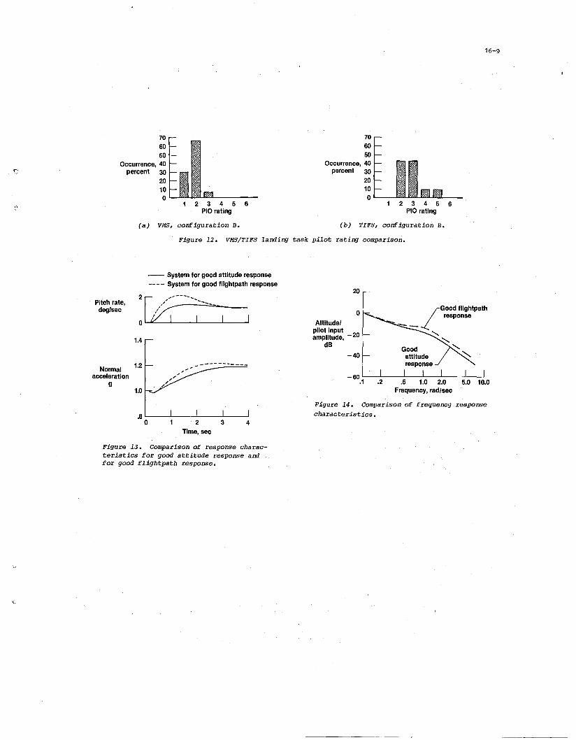
The histogram in Fig. 11 summarizes the results obtained. It is clear from this figure that theFSAA, with limited motion and visual cues, produced very little PIO tendency compared to the TIFS. In1979 and 1980, another series of simulations was made with the Ames VMS (Ref. 15) and the Calspan TIFS.The VMS had sufficient vertical motion to provide good vertical motion simulation, but it had the samevisual display that was used on the FSAA. In both of these simulations a very demanding task was usedto accentuate the PIO tendencies. A 46-m (150~ft) lateral offset was performed at 30 m (100 ft) abovethe runway, and a 4.6-m/sec (15-ft/sec) vertical gust was introduced at an altitude of approximately15 m (50 ft). This produced a task that would be unlikely in real life, but it provided a situationthat produced a pilot gain high enough to make the PIO tendencies of the vehicle apparent t9 the pilot.The results of theSe tests are summarized in Fig. 12; a significant difference still exists between themoving-base and flight simulations. On both of these simulators, after becoming familiar with the simulator, a normal straight-in approach and landing could be made without evidence of a PIO tendency.
16-5
Although the PIO tendencies were not the same (or the two simulations, the two simulators produced similar evaluations of the basic handling qualities for tasks less demanding than those that would producePIOs. The general conclusion (rom these tests is that flight si.l1lulation is probably the only reliablemethod of evaluating the 'landing characteristics~ The introduction of an artificial task produces pilotworkload levels nearer to the workload levels that can be encountered in flight, but even flight simulation does not produce the same sense of urgency that the actual flight environment produces.
7.0 ORBITAL FLIGHTS
The first orbital flight of the space transportation system (STS), made in 1981, represented a significant event in demonstrating the feasibility of making manual ,landings with an entry vehicle. Subsequent flights have demonstrated a capability to land on a 4570-m (15,000-ft) concrete runway in a routinemanner. In the early flights, variations in touchdown point and speed have resulted from a greater-thanpredicted value of low-speed L/D. Predictions are extremely important for the landing phase becausethere is no energy management below 610 m (2000 ft), and increases in L/D result in ,higher touchdownspeeds or longer landings. With the predicted data now updated with the flight results, this problemhas been reduced significantly. Overall, the STS flights have demonstrated a good manual landing capability, with acceptable landings being made in a variety of wind and turbulence conditions. The capability demonstrated so far is particularly impressive when one considers that each manual landing has beenperformed by a different pilot" thus reducing any of the pilot training advantages resulting from actualf light experience.
8.0 POTENTIAL IMPROVEMENTS
AS previously discussed, one disadvantage of the current orbiter control system is the normal acceleration response. The area where this is most significant is near the, ground where accurate control ofrate of sink is of paramount importance. Leveling off near the ground (such as bleeding off speed toobtain a better touchdown velocity) is difficult and is compounded by a tendency to balloon, particularlywhen in ground effects. Unlike a conventional transport, the orbiter has a considerable amount of excessenergy at a nominal landing speed of 200 knots, but because of the rapid deceleration (4 to 5 knots/sec),any significant ballooning can result fairly rapidly in a low-energy condition.
Flightpath control is difficult because of the lack of initial acceleration cues caused by the centerof-rotation effect and the slow rise time caused by the control-law design. The center-of-rotation effectcan only be cured by a configuration change and, as a result, is probably the most significant from adesign criteria standpoint. Active control technology allows the designer considerable flexibility inconfiguration selection and, together with current design trends toward multiple control surfaces, 'maylead to situations similar to that of the shuttle where the pilot response characteristics are considerably different from responses with other aircraft. There is a strong need for design criteria for pilotmotion parameters to avoid these problems in the future, particularly in those areas where basic configuration design is involved.
Because the center of rotation could not be changed, the normal acceleration rise time has beeninvestigated as a means of improving the flightpath control for landing. To speed up the accelerationresponse, the amount of pitch rate overshoot must be increased. An example of this system is shown inFig. 13; faster acceleration response compared to the current configuration is shown. An analysis ofthis type of system is given in Ref. 16. In ,addition to speeding up the normal acceleration response,an increase of the pitch rate overshoot produces an attitude response more like that of a conventionalaircraft over a limited frequency range as shown in Fig. 14. In the frequency range of 0.5 rad/sec to1.0 rad/sec the higher overshoot system exhibits attitude command characteristics rather than the ratecommand characteristics of the baseline system. It is in this frequency range where the pilot performsmuch of the flightpath control near touchdown.
Evaluations of the current system and the system with the higher pitch rate overshoot (the shapedpitch rate system) have produced some interesting results relative to pilot training. Most of the pilotswho have not had a lot of training with the current system generally prefer the shaped pitch rate systemfor landing. This system is felt to be predictable and has the same general characteristics of conventional aircraft where noseup pitch commands are required during the landing flare. For the baseline system, the flare maneuver often results in the need to use nosedown pitch commands to obtain the desiredflightpath. This group of pilots generally felt that the current configuration was less predictable andthat there was often a tendency to float near touchdown. For pilots who have had a lot of training withthe current system, the response characteristics of the current system are comfortable, and they preferthis system to the shaped pitch rate system for landing. Both groups of pilots find the current systemto be very good for all of the nonlanding tasks where very good attitude control is highly desirable.These results are particularly interesting for active control technology designers because although wehave the ability to produce almost any type of response that we desire, there will always be a strongtendency in the pilot community to assess these systems in terms of "normal airplane" response characteristics. This could very well lead to the perpetuation of "normal airplane" design criteria.
9.0 CONCLUDING REMARKS
The shuttle program was initiated as a bold and pioneering effort to develop a true spaceplane capable of returning from orbit and landing on a conventional runway. Some complex challenges were encountered in developing the longitudinal flying qualities required to land the orbiter manually in an operational environment. The longitudinal control system consists of a high-gain pitch rate command system.The design process made heavy use of simulation, and a robust system design was ensured by using a combination of aerodynamic and system uncertainties during the evaluations. Before the orbital flights,approach and landing test flights were made. The longitudinal flying qualities were quite good exceptfor a tendency for pilot-induced oscillation near landing. Two of the major contributions to the landing characteristics are the time delay and the center-of-rotation effects caused by, the elevons. Timedelays are somewhat inherent in high-gain digital control systems, but adequate testing has now beenperformed to provide adequate design criteria for future aircraft. Adequate design criteria do not exist

16-6
for center-of-rotation effects, and designers of future aircraft should consider nonstandard aircraftresponse carefully, particularly in those cases where a major configuration change Would be required tocorrect a deficiency. Changes in the operational procedures have reduced the difficulty of the landingtask, and an adaptive stick filter has been incorporated to reduce pilot-induced oscillations. Someimprovements may still be possible for the shuttle by increasing the pitch rate overshoot to improve thenormal acceleration response. This would make the response more like that of a conventional airplane;however, it appears that the current system is acceptable with adequate training. Fixed-base, movingbase, and in-flight simUlations have been used during the evaluations, and in general, flight simulation has been the only reliable means of assessing the low-speed longitudinal flying qualities problems.Overall, however, the orbiter control system design and the operational procedures have met the objectiveof providing the flying qualities necessary for a manual landing. An impressive manual landing capability for an unpowered vehicle with a low lift-to-drag ratio has been demonstrated, and precision landingsare now being made routinely. The shuttle program has used many advanced technologies and has demonstrated their application in an operational environment for the first time. In addition to providing anoperational space transportation system, the orbiter development program has also made a significantcontribution to the generic flying qualities and flight control "system technology for advanced aircraft.
REFERENCES
1. Smith, John W. and Edwards, John W. Design of a Nonlinear Adaptive Filter for Suppression ofShuttle Pilot-Induced Oscillation Tendencies, 1980, NASA TM-81349.
2. Powers, Bruce G. An Adaptive Stick-Gain to Reduce Pilot-Induced Oscillation Tendencies, 1982,AIAA 82-4078, J. Guidance and Control, vol. 5, no. 2, pp. 138-142.
3. Berry, Donald T., Powers, Bruce G., Szalai, Kenneth J., and Wilson, R. J. In-Flight Evaluation ofControl System Pure Time Delays, 1982, AIAA 80-1626R, J. Aircraft, vol. 19, no. 4, pp. 318-323.
4. Powers, Bruce G.Shuttle Program:
LOW-Speed Longitudinal Orbiter Flying Qualities, 1983, presented at "The SpaceFrom Challenge to Achievement," Johnson Space Center, Houston, TX.
5. Meyers, Thomas T., Johnston, Donald E., and McRuer, Duane. Space Shuttle Flying Qualities andFlight Control System Assessment Study, 1982, NASA CR-170391.
6. Meyers, T. T., Johnston, D. E., and McRuer, D. T. Space Shuttle Flying Qualities and Flight ControlSystem Assessment Study - Phase II, 1983, NASA CR-170406.
7. Meyers, T. T., Johnston, D. E., and McRuer, D. T. Space Shuttle Flying Qualities Criteria Assessment - Phase III, 1984, NASA CR-170407.
8. Weil, Joseph and Powers, Bruce G. Correlation of Predicted and Flight Derived Stability and ControlDerivatives - With Particular Application to Tailless Delta Wing Configurations, 1981, NASA"TM-81361.
9. Bayle, G. P. Space Shuttle Entry Flight Control Off-Nominal Design Considerations, 1984, AIAA J.Guidance and Control, vol. 7, no. 1, pp. 9-14.
10. Teper, Gary L., DiMarco, Richard, J., Ashkenas, Irving L., and Hoh, Roger H. Analyses of ShuttleOrbiter Approach and Landing Conditions, 1981, NASA CR-163108.
11. Neal, T. Peter and Smith, Rogers E. An In-Flight Investigation to Develop Control System DesignCriteria for Fighter Airplanes, 1970, AFFDL-TR-70-74.
12. Smith, Rogers E. Effects of Control System Dynamics on Fighter Approach and Landing LongitudinalFlying Qualities, 1978, AFFDL-TR-78-122.
13. Zuccaro, J. J. The Flight SimUlator for Advanced Aircraft - A New Aeronautical Research Tool, 1970,AIAA Paper 70-359.
'14. Reynolds, Philip A., Wasserman, Richard, Fabian, Gardner J., and Motyka, Paul R. In-Flight Simulator (TIFS), 1972, AFFDL-TR-72-39.
15. Jones, A. David. Operations Manual: Vertical Motion Simulator (VMS) S.08, 1980, NASA TM-81180.
16. Weingarten, Norman C. and Chalk, Charles R. Application of Calspan Pitch Rate Control System to theSpace Shuttle for Approach and Landing, 1983, NASA CR-170402.

16-7
Figure 2. Correlation of flight am predictedaerodynamic directional stability coefficient.
.003
.4 .6 1.0 2.0 3.0 4.0 6.0Mach number
.002
.001
-.001
Incrementbetweenflight andpredictedc~flIclent.. deg-1
Finalflare
Energymanagement
pha"e
3700 m(12.000 It)
Altitude(not to scale)
Figure 1. Laming trajectory.
2
Figure 3. pitch rate responsecriterion.
Pilotinput.
Pilotattitude
gain
~ ...~",,-.Sta"bleV ././'./''"",,-""- ~./
2 4Time, sec
o
Normalized 1 t:'.:Z<:.::c.::(4;::~~~~~pitch rate
Pilot altitude gain
Figure 4 •. Effect of nOnlinear stick gearingon pilot-vehicle closea-loop stability.
20
23Bandwidth. rad/sec
o
10 High·workload taSk}F·8DFBWPitch
0 Low·workload taskattitude @ Orbiter results on TIFSresonance.
simulation with lateraldB0 2 offset and vertical gust
Satisfactory ---------------_..,.. _.._--4
Pilot Unsatisfactory-10 rating...........6
908 Unllcceptable
"-10 I I I I
60 0 50 100 150 200 250 300 350Pilot Time delay, T, m seclead,deg Figure 6 ~ .Resul ts of the F-8 time-delay
30 study for the laming task.
Figure 5. pilot-vehicle closed-loop charac..teristics using Neal/Smith analysis.

16-8
1.5
2.0
2.5i-)
3.0
!l
24
20
16
Commandoutput, 12
deg
8
4
'0
Frequency,rad/sec
o
Figure 7. Adaptive stickgearirr; concept to reduce PIO,tendencies'.
Figure 8.··E~amp1e offrequen;g-deperrlentstick shapirr;.
4
Input andresponse, 2
deg
o
Attituderesponse---......
Time, sec
Sustainedoscillations
Yes
Figure 9. Orbiter attitude response forpilot pulse input. Airspeed = 190, kno,ts. Divergent
No1---------~4
Yes
Figure 10. PIO !:~,tiJW scale.
90,807060
Occurrence, 50percent 40
30201001.-......--..............................-
2 ,3 4,5 6PIO rating
(a) FSAA.
90807060
Occurrence, 50percent 40
302010o L....I-.J-..
2 3 4 5 6PIO rating
(b) TIFS.
Figure 11. FSAA/TIFS landing task PIO ratirr; comparison. Shuttle ALT conriguration.
16-9
1'.'
706050
Occurrence, 40percent 30
2010o
2 3 4 5 6PIO rating
706050
Occurrence, 40percent 30
20100'---
2 3 456PIO rating
(a) VMS, configuration B. (b) TIFS, configuration B.
Figure 12. VMS/TIFS laming task pilot rating comparison.
1.4
-- System for good attitude response---- System for good fIIghtpath response
P:;,~' :[k---~-----
5.0 10.0
o
20
-40
- 60 '--_'--_-'-_--...J.._--..1__--'-_-'
.1 .2 .5 1.0 2.0Frequency, rad/sec
Attltudelpilot Inputamplitude, - 20
dB
-----------
1.0
1.2Normalacceleration
g
.8 '-_-'--_-'I'------_...LI_---'Io 234
Time, sec
Figure 14. Comparison of frequency responsecharacteristics.
Figure 13. Comparison of response characteristics for good attitude response amfor good flightpath response.
~'.
1. Report No.
NASA TM-85910
I 2. Government Accession No'. 3. Recipient's Catalog No.
4. Title and Subtitle
Active Control Technology Experience With theSpace Shuttle in the Landing Regime
7. Author(sl
Bruce G. Powers
9. Performing Organization Name and Address
NASA Ames Research CenterDryden Flight Research FacilityP.O. Box 273Edwards, California 93523
12. Sponsoring Agency Name and Address
National Aeronautics and Space AdministrationWashington, D.C. 20546
15. Supplementary Notes
5. Report Date
October 1984
6. Performing Organization Code
8. Performing Organization Report No.
H-1260
10. Work Unit No.
11. cOntract or Grant No.
13. Type of Report and Period Covered
Technical Memorandum
14. Sponsoring Agency Code
RTOP 505-34-01
This paper was prepared for presentation at the AGARD Flight Mechanics Panel SYmposium onActi ve Control Systems, Toronto, Canada, Oct. 15 to 18, '1984.
16. Abstract
The shuttle program took on the challenge of providing a manual landing capability for an operational vehicle returning from orbit. Some complex challenges wereencountered in developing the longitudinal flying qualities required to land theorbiter manually in an operational environment. ~pproach and landing test flightsindicated a tendency for pilot"'induced 0lJcillation near landing. Changes in theoperational procedures reduced the difficulty of the landing task, and an adaptivestick filter was incorporated to redUce the severity of any pilot-irtducedoscillatory motions. Fixed-base, moving-base, and in-flight simulations were used for theevaluations, and in general, flight simulation has been the only reliable means ofassessing the low-speed longitudinal flying qualities problems. Overall, ·the orbitercontrol system and operational procedures have produced a' good capability for rou'"tinely performing precise landings in a large, unpowered vehicle with a low lift-to'"drag ratio.
17. Key Words (Suggested by Author/sl)
Space shuttleControl systemsFlying qualities
18. Distribution Statement
Unclassified-Unlimited
STAR category 08
No. of Pages19. Securit\' Classif. (of this report)
Unclassified
20. Security Classif. (of this page)
I Unclassified 1
21.
10
22. Price'
A02
*For sale by the National Technical Information Service, Springfield, Virginia 22161


e '1111""IIII~~~11111Ifmnlrlll~llm~II"II""3 1176 01328 5623"~---'~~~J -_._"--" --"-----.---'--"--->-----.
DO NOT REMOVE SLIP FROM MATERIAL
Delete your name from this slip when returning materialto the library.
NAME MS
Cu. D.C;}\~~ t/>IJ
1
'"I:g
NASA Langley (Rev. May 1988) RIAD N-75
'f"