acs 600 installation and start-up guide modbus plus ... · acs 600 installation and start-up guide...
TRANSCRIPT

ACS 600 Installation andStart-up Guide
Modbus Plus Adapter ModuleNMBP-01


1996 ABB Industry
Modbus Plus Adapter ModuleNMBP-01
Installation andStart-up Guide
Oy. All Rights Reserved.
3AFY 58919802 R0125 REV B
EFFECTIVE: 1996-03-01SUPERSEDES: None

ii
Installation and Start-up Guide for NMBP-01
Safety Instructions
Overview This chapter states the safety instructions that must be followed when installing and operating the NMBP-01 Modbus Plus Adapter Module. If neglected, physical injury and death may follow, or damage may occur to the frequency converter, the motor and driven equipment. The material in this chapter must be studied before attempting any work on, or with, the unit.
Warnings and Notes This manual distinguishes two sorts of safety instructions. Warnings are used to inform of conditions which can, if proper steps are not taken, lead to a serious fault condition, physical injury and death. Notes are used when the reader is required to pay special attention or when there is additional information available on the subject. Notes are less crucial than Warnings, but should not be disregarded.
Warnings Readers are informed of situations that can result in serious physical injury and/or serious damage to equipment with the following symbols:
Notes Readers are notified of the need for special attention or additional information available on the subject with the following symbols:
Dangerous Voltage Warning: warns of situations in which a high voltage can cause physical injury and/or damage equipment. The text next to this symbol describes ways to avoid the danger.
General Warning: warns of situations which can cause physical injury and/or damage equipment by means other than electrical. The text next to this symbol describes ways to avoid the danger.
Electrostatic Discharge Warning: warns of situations in which an electrostatic discharge can damage equipment. The text next to this symbol describes ways to avoid the danger.
CAUTION! Caution aims to draw special attention to a particular issue.
Note: Note gives additional information or points out more information available on the subject.
Installation and Start-up Guide for NMBP-01 iii
Safety Instructions
General Safety Instructions
WARNING! All electrical installation and maintenance work on the ACS 600 should be carried out by qualified electricians.
The ACS 600 and adjoining equipment must be properly earthed.
Do not attempt any work on a powered ACS 600. After switching off the mains, always allow the intermediate circuit capacitors 5 minutes to discharge before working on the frequency converter, the motor or the motor cable. It is good practice to check (with a voltage indicating instrument) that the frequency converter is in fact discharged before beginning work.
The ACS 600 motor cable terminals are at a dangerously high voltage when mains power is applied, regardless of motor operation.
There can be dangerous voltages inside the ACS 600 from external control circuits when the ACS 600 mains power is shut off. Exercise appropriate care when working with the unit. Neglecting these instructions can cause physical injury and death.
WARNING! There are several automatic reset functions in theACS 600. If selected, they reset the unit and resume operation after a fault. These functions should not be selected if other equipment is not compatible with this kind of operation, or dangerous situations can be caused by such action.
More Warnings and Notes are printed at appropriate instances along the text.
iv Installation and Start-up Guide for NMBP-01
Table of Contents
Chapter 1 – Introduction
How to Use this Guide ................................................................................................................................ 1-1Conventions Used in this Guide .................................................................................................................. 1-2
Data set.................................................................................................................................................. 1-2Global Data ........................................................................................................................................... 1-24XXXX Register Area .......................................................................................................................... 1-2
Related Publications ................................................................................................................................... 1-2
Chapter 2 – Overview
Overview .................................................................................................................................................... 2-1Delivery Check...................................................................................................................................... 2-1Compatibility......................................................................................................................................... 2-1
Warranty and Liability Information ........................................................................................................... 2-2
Chapter 3 – Mechanical Installation
Overview ..................................................................................................................................................... 3-1Mounting Outside the ACS 600 .................................................................................................................. 3-2Mounting Inside the ACS 601..................................................................................................................... 3-3Mounting Inside the ACS 603..................................................................................................................... 3-4
Chapter 4 – Electrical Installation
NMBP-01 Connectors ................................................................................................................................ 4-1Wiring ......................................................................................................................................................... 4-2
24 V d.c. Power ..................................................................................................................................... 4-2Fibre Link.............................................................................................................................................. 4-4Modbus Plus .......................................................................................................................................... 4-6
Chapter 5 – Programming
General ....................................................................................................................................................... 5-1Modbus Plus Configuration ........................................................................................................................ 5-1
Group 51 Modbus Plus.......................................................................................................................... 5-3Control Locations ....................................................................................................................................... 5-6Output Selections ....................................................................................................................................... 5-8Data sets ..................................................................................................................................................... 5-8
Data set 1 - CONTROL......................................................................................................................... 5-9Data set 2 - REFERENCE 1 ................................................................................................................ 5-10Data set 3 - REFERENCE 2 ................................................................................................................ 5-10Data set 4 - STATUS .......................................................................................................................... 5-11Data set 5 - ACTUAL 1 ...................................................................................................................... 5-12Data set 6 - ACTUAL 2 ...................................................................................................................... 5-12
Communication Loss Setup ...................................................................................................................... 5-12
Installation and Start-up Guide for NMBP-01 v
Table of Contents
Chapter 6 – Communication
Introduction to Modbus Plus .......................................................................................................................6-1Program Paths ........................................................................................................................................ 6-1Routing for ACS 600 ............................................................................................................................. 6-2Register Read and Write ........................................................................................................................ 6-3Exception Codes .................................................................................................................................... 6-5Global Data ............................................................................................................................................ 6-5
Data Update ................................................................................................................................................6-6
Chapter 7 – Fault Tracing
Installation Problems ............................................................................................................................. 7-1Drive Setup ............................................................................................................................................ 7-1PLC Programming ................................................................................................................................. 7-1Module Diagnostics ............................................................................................................................... 7-2Modbus Plus LED.................................................................................................................................. 7-3MSTR Block Error Codes .....................................................................................................................7-4Hardware Failures.................................................................................................................................. 7-6
Appendix A – Technical Data
Protocols ............................................................................................................................................... A-1Power Supply........................................................................................................................................ A-1Dimensions ........................................................................................................................................... A-1Mounting............................................................................................................................................... A-1Storage .................................................................................................................................................. A-1Operational ........................................................................................................................................... A-1Noise Immunity / Emissions .................................................................................................................A-1
Appendix B – Parameter Scaling
Appendix C – Assembly Drawings
vi Installation and Start-up Guide for NMBP-01
Chapter 1 – Introduction
This chapter introduces the contents and divisions of this Guide.
How to Use this Guide The purpose of this Guide is to provide the information necessary to install, commission, use, and to fault diagnose the Modbus Plus communication adapter.
Safety Instructions gives the general safety instructions which apply to ACS 600 and all of its option modules. This chapter also describes the for-mats and meanings for various warnings used within this guide.
Chapter 1 – Introduction,the chapter you are reading now, contains a short description of this manual and a list of related publications.
Chapter 2 – Overview contains a short description of the Modbus Plus net-work and of the Modbus Plus adapter module. Delivery check list for field installation, and liability of manufacturer.
Chapter 3 – Mechanical Installation contains instructions for module plac-ing and mounting.
Chapter 4 – Electrical Installation contains instructions for wiring the mod-ule to power supply, Modbus Plus network, and to the ACS 600 drive.
Chapter 5 – Programming explains how to program the ACS 600 drive for the Modbus Plus communication, and what additional parameters are avail-able with the module.
Chapter 6 – Communication describes what drive features and parameters can be accessed through the Modbus Plus communication module. There is also information on drive control and how to read the drive actual values and status information through the Modbus Plus connection.
This chapter also discusses the performance of the Modbus Plus connection.
Chapter 7 – Fault Tracing describes how to fault diagnose the Modbus Plus connection during installation, commissioning, and normal operation.
Installation and Start-up Guide for NMBP-01 1-1
Chapter 1 – Introduction
Appendix A – Technical Data contains the technical information on the Mod-bus Plus module.
Appendix B – Parameter Scaling contains a complete list of all the parame-ters, their 4xxxx register addresses, and the scaling accessible through the Modbus Plus network.
Appendix C – Assembly Drawings contains drawings that assist in placing the option module.
Conventions Used in this Guide
This Guide uses some terms and conventions that all readers might not be familiar with. Some of these terms are described here.
Data set Data set is a fast control and feedback value area in the ACS 600 drive. Data sets give the fastest possible control to the drive.
Global Data The Modbus Plus network has a service called Global Data. This is a fast data transfer between devices on the Modbus Plus network. Global Data is designed for sending time-critical control or feedback values to and from devices on the network. Modicon PLCs and ACS 600 drives support the glo-bal data transfer.
4XXXX Register Area Modicon PLCs have a signed integer data table area, which is used for Ana-logue output modules and for storing temporary or set-point values. These registers are in the address area starting from 40001. The last register address available on PLCs depends on the available memory, but is less than 49999.
The ACS 600 drive simulates this area by providing a read and write access to its parameters through this register address area.
Related Publications ACS 600 Programming Manual
Modicon Modbus Plus Network Planning and Installation Guide.
1-2 Installation and Start-up Guide for NMBP-01
Chapter 2 – Overview
This chapter describes the NMBP-01 Module, and gives the Warranty and Liability information of the Manufacturer.
Overview The NMBP-01 Modbus Plus Adapter Module is for connecting the ACS 600 drive directly to the Modicon Modbus Plus network.
The NMBP-01 supports the read and write access to the drive parameters and ‘ data sets’ , as well as receiving and sending global data for critical drivecontrol and feedback values.
Delivery Check The field installation Modbus Plus option package include:
• NMBP-01 Adapter Module
• Three pairs of fibre optic cables
• Mounting rail
• Installation and Start-up Guide for NMBP-01.
Compatibility The NMBP-01 has been tested and approved by Modicon as a part of theModConnect program acceptance.
Installation and Start-up Guide for NMBP-01 2-1
Chapter 2 – Overview
Warranty and Liability Information
The warranty for your ABB drive and options covers manufacturing defects. The manufacturer carries no responsibility for damage due to transport or unpacking.
In no event and under no circumstances shall the manufacturer be liable for damages and failures due to misuse, abuse, improper installation, or abnormal conditions of temperature, dust, or corrosives, or failures due to operation above rated capacities. Nor shall the manufacturer ever be liable for conse-quential and incidental damages.
The period of manufacturer’s warranty is 12 months, and not more than 18 months, from the date of delivery.
Extended warranty may be available with certified start-up. Contact your local distributor for details.
Your local ABB Drives company or distributor may have a different warranty period, which is specified in their sales terms, conditions, and warranty terms.
If you have any questions concerning your ABB drive, contact your local dis-tributor or ABB Drives office.
The technical data and specifications are valid at the time of printing. ABB reserves the right to subsequent alterations.
2-2 Installation and Start-up Guide for NMBP-01
Chapter 3 – Mechanical Installation
Overview This chapter contains the option module mounting instructions.
ACS 601 For ACS 601-0005-3/0006-5 to ACS 601-0016-3/0020-5, the option modules are to be mounted outside the ACS 601 housing. See page 3-2 for mounting instructions.
For ACS 601-0020-3/0025-5 to ACS 601-0120-3/0140-5, one option module can be mounted inside the ACS 601 housing (see page 3-3 for mounting instructions). The additional modules are to be mounted outside the ACS 601 housing; see page 3-2 for instructions.
ACS 602 The option modules are to be mounted outside the ACS 602 unit. See next page for mounting instructions.
ACS 603 For ACS 603-0100-3/0120-5 and ACS 603-0120-3/0140-5, one option module can be mounted inside the frequency converter unit installed inside the ACS 603 cabinet (see page 3-4 for mounting instructions). Six option modules (plus the NPSM-01 Power Supply module) can be mounted inside the ACS 603 cabinet (see page 3-4 for instructions). The additional modules are to be mounted outside the ACS 603 cabinet; see page 3-2 for instructions.
ACS 604 The option modules are to be mounted outside the ACS 604 unit. See page 3-2 for mounting instructions.
Installation and Start-up Guide for NMBP-01 3-1
Chapter 3 – Mechanical Installation
Mounting Outside the ACS 600
Choose the location for the module. Note the following:
• Note the free space requirements for the ACS 600. See the ACS 601 (602/603/604) Installation and Start-up Manual.
• The cabling instructions must be followed (see Chapter 4,starting page 4-1). Also, the length of the fibre optic cables included in the option package restrict the distance between the module and the ACS 600.
• The ambient conditions should be taken into account (see Appendix B). The enclosure class of the module is IP 20.
• The mounting rail onto which the option module is to be mounted must be earthed to a noiseless earth. If the rail is not mounted on a properly earthed base, a separate earthing conductor must be used. The conductor must be as short as possible and the cross-sectional area must be 6 mm2 at least. Note: No solid copper conductor may be used (stranded wire allowed only).
Mounting instructions:
1. Switch off all dangerous voltages in the cabinet that the module is to be mounted in.
2. Fasten the rail and ensure the proper earthing (see instructions above).
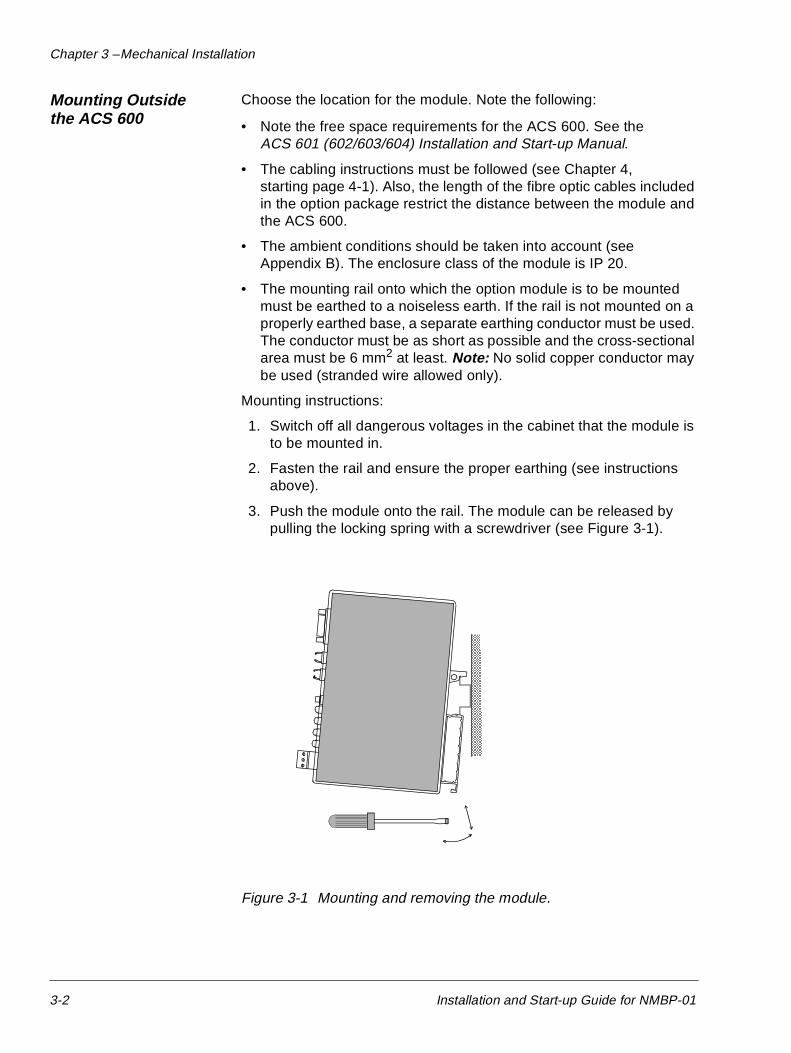
3. Push the module onto the rail. The module can be released by pulling the locking spring with a screwdriver (see Figure 3-1).
Figure 3-1 Mounting and removing the module.
3-2 Installation and Start-up Guide for NMBP-01
Chapter 3 – Mechanical Installation
Mounting Inside the ACS 601
The work inside the frequency converter should be carried out by a qualified electrician only.
WARNING! Pay attention to the slowly discharging voltage of the capacitor bank and the voltages that are connected from external control circuits to the digital inputs and to the relay outputs.
WARNING! Do not touch the printed circuit boards. The integrated circuits are extremely sensitive to electrostatic discharge.
Mounting instructions:
1. Stop the drive.
2. Switch off the power supply of the drive and all dangerous voltages connected to the digital inputs and relay outputs.
3. Wait for five minutes to ensure that the capacitors in the intermediate circuit have discharged.
4. Remove the front cover of the converter.
5. Ensure that the mains cable, motor cable and capacitor bank (UDC+ and UDC-) are not powered.
6. Locate the position for the module (see Appendix D - Assembly Drawings). Remove the two screws from the assembly plate. Fasten the mounting rail to its place using the two screws.
7. Push the module onto the rail. The module can be released by pulling the locking spring with a screwdriver (see Figure 3-1).
Installation and Start-up Guide for NMBP-01 3-3
Chapter 3 – Mechanical Installation
Mounting Inside the ACS 603
The work inside the frequency converter should be carried out by a qualified electrician only.
WARNING! Pay attention to the slowly discharging voltage of the capacitor bank and the voltages that are connected from external control circuits to the digital inputs and to the relay outputs.
WARNING! Do not touch the printed circuit boards. The integrated circuits are extremely sensitive to electrostatic discharge.
Mounting instructions:
1. Stop the drive.
2. Switch off the power supply of the drive and all dangerous voltages connected to the digital inputs and relay outputs. Lock the fuse switch to the open position.
3. Wait for five minutes to ensure that the capacitors in the intermediate circuit have discharged.
4. Open the front door of the cabinet.
5. Locate the position for the module (see Appendix D - Assembly Drawings).
6. If the module can be mounted inside the converter unit(in ACS-603-0100-3/0120-5 and ACS 603-0120-3/0140-5,there is room for one option module):
• Remove the front cover of the converter unit.
• Ensure that the mains cable, motor cable and capacitor bank (UDC+ and UDC-) are not powered.
• Remove the two screws from the assembly plate.
• Fasten the mounting rail to its place using the two screws.
7. Push the module onto the rail. The module can be released by pulling the locking spring with a screwdriver (see Figure 3-1).
3-4 Installation and Start-up Guide for NMBP-01
Chapter 4 – Electrical Installation
This chapter gives wiring instructions for wiring the NMBP-01 Modbus Plus option module to 24 VDC power, fibre link connection to the drive, and to the Modbus Plus network.
WARNING! Verify that the ACS 600 is not powered before starting the installation.
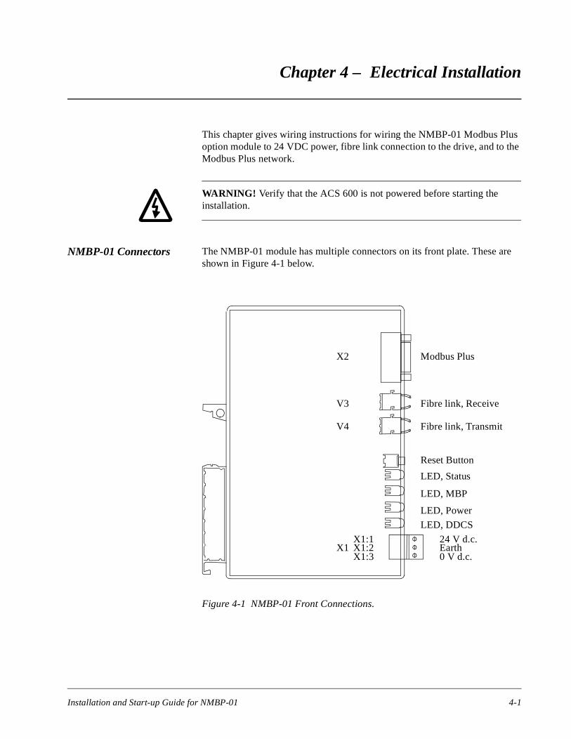
NMBP-01 Connectors The NMBP-01 module has multiple connectors on its front plate. These are shown in Figure 4-1 below.
Figure 4-1 NMBP-01 Front Connections.
Modbus Plus
Fibre link, Receive
Fibre link, Transmit
Reset Button
LED, Status
LED, MBP
LED, Power
LED, DDCS
24 V d.c.Earth0 V d.c.
X2
V3
V4
X1 X1:2X1:1
X1:3
Installation and Start-up Guide for NMBP-01 4-1
Chapter 4 – Electrical Installation
d
00 is up-
I/O
X1 This is the power connector for the module with the following terminals:
• X1:1 is for regulated 24 V d.c.
• X1:2 is for earthing the shield of the X2 Modbus Plus network
• X1:3 is for 0 V d.c.
X2 This is the standard Modbus Plus connector.
V3 This is the fibre link receive from the drive.
V4 This is the fibre link transmit to the drive.
Wiring The 24 V d.c. power should be connected to the NMBP-01 using insulate
wire with 16 – 20 AWG (0.5 to 1.5 mm2).
24 V d.c. Power The Modbus Plus module needs to be supplied from a stabilised24 V d.c. auxiliary power supply. This power can be taken from the ACS 6drive to a maximum of one option module per drive. If this auxiliary poweralready in use, the NMBP-01 must be powered from an external power sply.
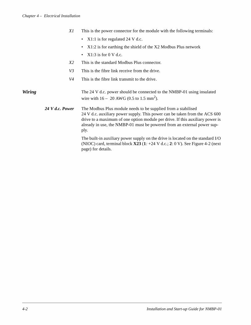
The built-in auxiliary power supply on the drive is located on the standard (NIOC) card, terminal block X23 (1: +24 V d.c.; 2: 0 V). See Figure 4-2 (next page) for details.
4-2 Installation and Start-up Guide for NMBP-01
Chapter 4 – Electrical Installation
Figure 4-2 Drive Auxiliary Power Supply.
The power and earthing connector is on the bottom of the option module. The connection is shown in Figure 4-3 below.
Figure 4-3 NMBP-01 Power Connector.
In this figure, the 24 V d.c. is connected to terminal 1, and the power0 V d.c. to 3. Terminal 2 is for signal earth, which is used to terminate the shield of the Modbus Plus network. This signal earth must be connected to a noise-free earth, and not to a earth where high power devices are earthed.
X25
X27
X26
X28
X29
X21
X22
X24
X23
V25
V26
+24 VDC
GND (0 VDC)
X1:1
X1:3
X1:1 +24 VDC (to X23:1)
X1:2 GND (Signal earth)
X1:3 GND (0 V d.c.) (to X23:2)
Installation and Start-up Guide for NMBP-01 4-3
Chapter 4 – Electrical Installation
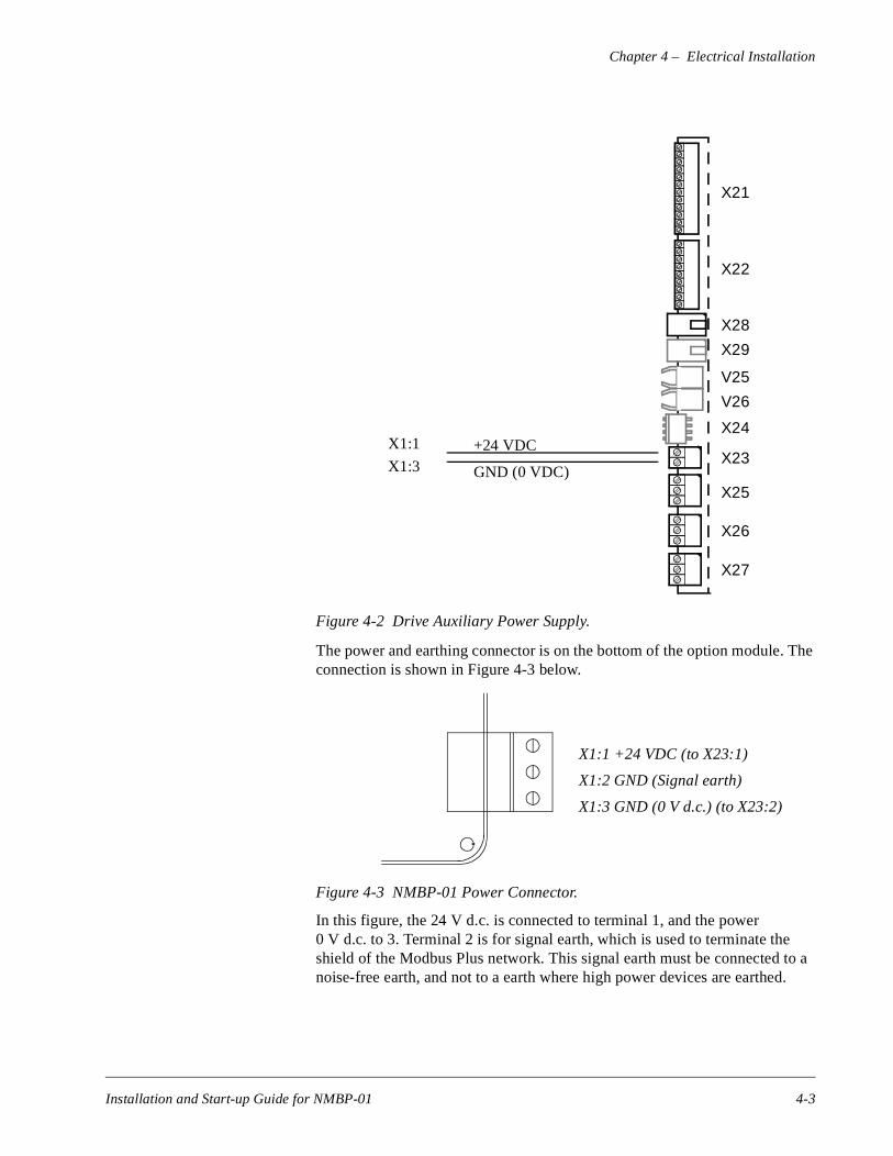
Fibre Link The fibre link is used for electrically isolating the option modules from the high power components. Handle the optic cables with care. For ratings of the optic cables ABB is supplying with the drives, see Table 4-1 below.
Table 4-1 Fibre Optic Cable Ratings.
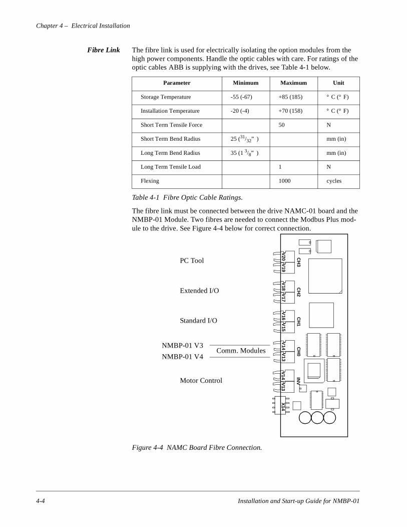
The fibre link must be connected between the drive NAMC-01 board and the NMBP-01 Module. Two fibres are needed to connect the Modbus Plus mod-ule to the drive. See Figure 4-4 below for correct connection.
Figure 4-4 NAMC Board Fibre Connection.
Parameter Minimum Maximum Unit
Storage Temperature -55 (-67) +85 (185) ° C (° F)
Installation Temperature -20 (-4) +70 (158) ° C (° F)
Short Term Tensile Force 50 N
Short Term Bend Radius 25 (31/32” ) mm (in)
Long Term Bend Radius 35 (1 3/8” ) mm (in)
Long Term Tensile Load 1 N
Flexing 1000 cycles
Comm. Modules
CH
3
V20
V19
V18
V17
V16
V15
V14
V13
CH
2C
H1
CH
0
V14
V13
INV
X14
PC Tool
Extended I/O
Standard I/O
Motor Control
NMBP-01 V3
NMBP-01 V4
4-4 Installation and Start-up Guide for NMBP-01
Chapter 4 – Electrical Installation
Modbus Plus The NMBP-01 option module has the standard 9-pin D-shell Modbus Plus connector on top of the front plate.
The following chapters are used by permission of Modicon. These chapters are taken from Modicon publication “ Modbus Plus Network Planning and Installation Guide” (GM-MBPL-001 Rev. D).
Modbus Plus Cable The cable type specified for network use is:
Manufacturer: Belden Corporation
Telephone: (317) 983-5200
Cable Type: 9841
Description: Twisted pair, shielded, with insulating outer jacket NEC/UL CM (communications) for use in industrial environments
This cable is available from Modicon as the following part numbers:
97-9841-100 MBPlus 100 Foot Reel
97-9841-500 MBPlus 500 Foot Reel
97-9841-01K MBPlus 1000 Foot Reel
For ordering information, contact Modicon Customer Service at the following telephone numbers. Ask for Customer Service Order Entry.
North America: (800) 468-5342
International: (508) 794-0800
Your cable will run directly between the network device locations. Each cable segment must be a continuous run between the device connectors at two loca-tions. The use of splices, taps, splitters, or any other configurations such as ’star’ or ’tree’ configurations, is not allowed. The only allowed media compo-nents are the network cable and network device connectors.
You will typically plan your cable runs according to the vertical rises and hor-izontal distances between sites. When you order cable, you will be ordering it by reels of fixed length. Order reels of sufficient length to allow continuous runs between the network devices. Provide excess length at each site for ser-vice loops, strain reliefs, and dressing.
Installation and Start-up Guide for NMBP-01 4-5
Chapter 4 – Electrical Installation
nec-o
et- the e is
e n-
nec-the
e and
e
e 4-
Modbus Plus Connectors Two types of connectors are available from Modicon for connecting devices to the network:
• Each in-line drop requires a line connector, Modicon part number AS-MBKT-085. This part number contains one connector.
• The drops at the two ends of the cable each require a terminating contor, Modicon part number AS-MBKT-185. This part number contains twconnectors.
You should plan to order a sufficient quantity of connectors to allow extraones for service access and spares.
Modbus Plus ConnectorInstallation Tool
A special tool is available from Modicon for installing connectors on the nwork cable. Use of the tool will ensure positive electrical contact betweenconnector and cable, as well as make for a more rapid installation. Its ushighly recommended. Its part number is:
AS-MBPL-001 Modbus Plus Connector Assembly Tool
Modbus Plus Cable Imped-ance Termination
When the terminating connectors are installed on the two extreme ends of thcable, they furnish the proper terminating impedance for the network. Thecable termination is maintained regardless of whether a node device is conected to either end of the cable. No other termination is required.
It is not necessary to provide an external matching termination to any contor. Any connector can be disconnected from its device without affecting network impedance.
Modbus Plus NetworkEarthing
The entire network cable, including its shield, should remain isolated fromexternal earth sources. No connection should be made between the cablthe plant earthing system or the panel earthing connection at any point.
Earthing systems should connect to each device's dedicated earth terminal, not to the network cable. The cable earth will be supplied by its network cablconnection to the device.
The cable shield earth is connected to terminal X1:3 (see Figure 4-2, pag3) on the power connector on the NMBP-01 Module.
4-6 Installation and Start-up Guide for NMBP-01
Chapter 5 – Programming
This chapter describes how to program the ACS 600 drive for the Modbus Plus communication.
The reader should be already familiar with how to program the drive parame-ters using the CDP-311 Control Panel, and how the parameters are arranged in groups. For details see the ACS 600 Programming Manual.
General After installing and wiring the NMBP-01 Module to the ACS 600 drive, the first step is to alert the drive that there is a communication module installed. Before this communication option module is used, Parameter 98.2 COMM MODULE must be changed from NO to YES.
After this, Parameter Group 51 can be programmed for the correct configura-tion.
When Parameter 98.2 is set to YES, there are new selections available to Con-trol Location parameters which are not described in the basic ACS 600 Pro-gramming Manual.
Modbus Plus Configuration
The NMBP-01 Modbus Plus Module is completely configured through the control panel. There are no internal DIP switches or jumpers to be set on the NMBP-01 option module.
When the NMBP-01 module is connected to the drive and it receives its power, the option module will read its setup parameters from the drive. Dur-ing the initial power-up sequence, the Modbus Plus module configuration information is set to default values, which can be changed from the control panel.
Installation and Start-up Guide for NMBP-01 5-1
Chapter 5 – Programming
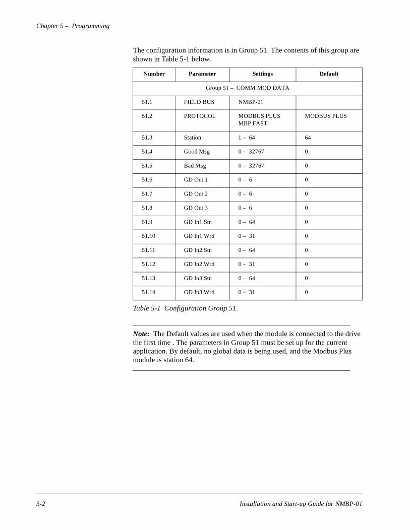
The configuration information is in Group 51. The contents of this group are shown in Table 5-1 below.
Table 5-1 Configuration Group 51.
Note: The Default values are used when the module is connected to the drive the first time . The parameters in Group 51 must be set up for the current application. By default, no global data is being used, and the Modbus Plus module is station 64.
Number Parameter Settings Default
Group 51 – COMM MOD DATA
51.1 FIELD BUS NMBP-01
51.2 PROTOCOL MODBUS PLUSMBP FAST
MODBUS PLUS
51.3 Station 1 – 64 64
51.4 Good Msg 0 – 32767 0
51.5 Bad Msg 0 – 32767 0
51.6 GD Out 1 0 – 6 0
51.7 GD Out 2 0 – 6 0
51.8 GD Out 3 0 – 6 0
51.9 GD In1 Stn 0 – 64 0
51.10 GD In1 Wrd 0 – 31 0
51.11 GD In2 Stn 0 – 64 0
51.12 GD In2 Wrd 0 – 31 0
51.13 GD In3 Stn 0 – 64 0
51.14 GD In3 Wrd 0 – 31 0
5-2 Installation and Start-up Guide for NMBP-01
Chapter 5 – Programming
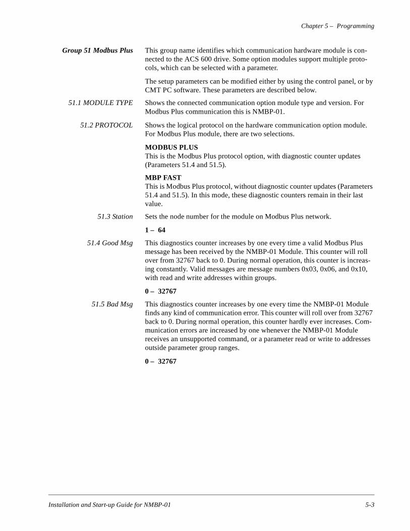
Group 51 Modbus Plus This group name identifies which communication hardware module is con-nected to the ACS 600 drive. Some option modules support multiple proto-cols, which can be selected with a parameter.
The setup parameters can be modified either by using the control panel, or by CMT PC software. These parameters are described below.
51.1 MODULE TYPE Shows the connected communication option module type and version. For Modbus Plus communication this is NMBP-01.
51.2 PROTOCOL Shows the logical protocol on the hardware communication option module. For Modbus Plus module, there are two selections.
MODBUS PLUSThis is the Modbus Plus protocol option, with diagnostic counter updates (Parameters 51.4 and 51.5).
MBP FASTThis is Modbus Plus protocol, without diagnostic counter updates (Parameters 51.4 and 51.5). In this mode, these diagnostic counters remain in their last value.
51.3 Station Sets the node number for the module on Modbus Plus network.
1 – 64
51.4 Good Msg This diagnostics counter increases by one every time a valid Modbus Plus message has been received by the NMBP-01 Module. This counter will roll over from 32767 back to 0. During normal operation, this counter is increas-ing constantly. Valid messages are message numbers 0x03, 0x06, and 0x10, with read and write addresses within groups.
0 – 32767
51.5 Bad Msg This diagnostics counter increases by one every time the NMBP-01 Module finds any kind of communication error. This counter will roll over from 32767 back to 0. During normal operation, this counter hardly ever increases. Com-munication errors are increased by one whenever the NMBP-01 Module receives an unsupported command, or a parameter read or write to addresses outside parameter group ranges.
0 – 32767
Installation and Start-up Guide for NMBP-01 5-3

Chapter 5 – Programming
51.6 GD Out 1 Defines what is sent out on the first word of the global data. The selection is limited to the high-speed data set information on the ACS 600 drive.
CNTRL WORDThe Control word is used for start/stop control, and for resetting the faults on the drive. For details see Table 5-2.
REFERENCE 1Selection sends out the current Reference 1 value.
REFERENCE 2Selection sends out the current Reference 2 value.
STATUSSelection sends out the current status word.
ACTUAL 1Selection sends out the actual value corresponding to Analogue Output 1.
ACTUAL 2Selection sends out the actual value corresponding to Analogue Output 2.
51.7 GD Out 2 Defines what is sent out on the second word of global data. The selection is limited to high-speed data set information on the ACS 600 drive. The choices are the same as Parameter 51.6 (GD Out 1).
51.8 GD Out 3 Defines what is sent out on the third word of global data. The selection is lim-ited to high-speed data set information on the ACS 600 drive. The choices are the same as Parameter 51.6 (GD Out 1).
51.9 GD In1 Stn This parameter and Parameter 51.10 GD In1 Wrd defines what data is received for data set 1. This parameter defines the source station for Global Data which is placed to the Control Word.
0Identifies that the control word is not received through Global Data.
1 – 64Identifies the source station for Global Data.
51.10 GD In1 Wrd This parameter and Parameter 51.9 GD In1 Stn defines what data is received for data set 1. This parameter defines the word number on the Global Data which is placed to the Control Word.
0 – 31The word number of the Global Data.
5-4 Installation and Start-up Guide for NMBP-01
Chapter 5 – Programming
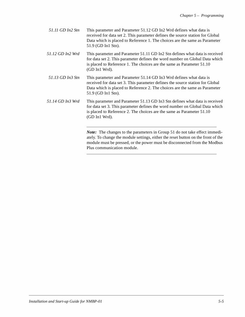
51.11 GD In2 Stn This parameter and Parameter 51.12 GD In2 Wrd defines what data is received for data set 2. This parameter defines the source station for Global Data which is placed to Reference 1. The choices are the same as Parameter 51.9 (GD In1 Stn).
51.12 GD In2 Wrd This parameter and Parameter 51.11 GD In2 Stn defines what data is received for data set 2. This parameter defines the word number on Global Data which is placed to Reference 1. The choices are the same as Parameter 51.10 (GD In1 Wrd).
51.13 GD In3 Stn This parameter and Parameter 51.14 GD In3 Wrd defines what data is received for data set 3. This parameter defines the source station for Global Data which is placed to Reference 2. The choices are the same as Parameter 51.9 (GD In1 Stn).
51.14 GD In3 Wrd This parameter and Parameter 51.13 GD In3 Stn defines what data is received for data set 3. This parameter defines the word number on Global Data which is placed to Reference 2. The choices are the same as Parameter 51.10 (GD In1 Wrd).
Note: The changes to the parameters in Group 51 do not take effect immedi-ately. To change the module settings, either the reset button on the front of the module must be pressed, or the power must be disconnected from the Modbus Plus communication module.
Installation and Start-up Guide for NMBP-01 5-5
Chapter 5 – Programming
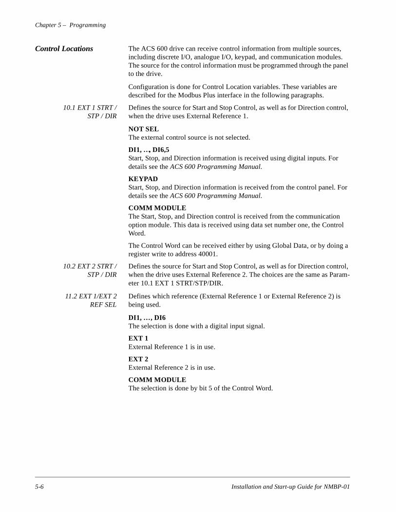
Control Locations The ACS 600 drive can receive control information from multiple sources, including discrete I/O, analogue I/O, keypad, and communication modules. The source for the control information must be programmed through the panel to the drive.
Configuration is done for Control Location variables. These variables are described for the Modbus Plus interface in the following paragraphs.
10.1 EXT 1 STRT /STP / DIR
Defines the source for Start and Stop Control, as well as for Direction control, when the drive uses External Reference 1.
NOT SELThe external control source is not selected.
DI1, …, DI6,5Start, Stop, and Direction information is received using digital inputs. For details see the ACS 600 Programming Manual.
KEYPADStart, Stop, and Direction information is received from the control panel. For details see the ACS 600 Programming Manual.
COMM MODULEThe Start, Stop, and Direction control is received from the communication option module. This data is received using data set number one, the Control Word.
The Control Word can be received either by using Global Data, or by doing a register write to address 40001.
10.2 EXT 2 STRT /STP / DIR
Defines the source for Start and Stop Control, as well as for Direction control, when the drive uses External Reference 2. The choices are the same as Param-eter 10.1 EXT 1 STRT/STP/DIR.
11.2 EXT 1/EXT 2REF SEL
Defines which reference (External Reference 1 or External Reference 2) is being used.
DI1, … , DI6The selection is done with a digital input signal.
EXT 1External Reference 1 is in use.
EXT 2External Reference 2 is in use.
COMM MODULEThe selection is done by bit 5 of the Control Word.
5-6 Installation and Start-up Guide for NMBP-01
Chapter 5 – Programming
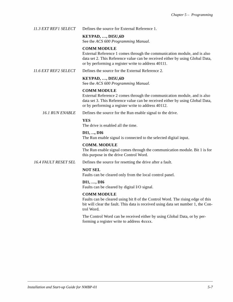
11.3 EXT REF1 SELECT Defines the source for External Reference 1.
KEYPAD, … , DI5U,6DSee the ACS 600 Programming Manual.
COMM MODULEExternal Reference 1 comes through the communication module, and is also data set 2. This Reference value can be received either by using Global Data, or by performing a register write to address 40111.
11.6 EXT REF2 SELECT Defines the source for the External Reference 2.
KEYPAD, … , DI5U,6DSee the ACS 600 Programming Manual.
COMM MODULEExternal Reference 2 comes through the communication module, and is also data set 3. This Reference value can be received either by using Global Data, or by performing a register write to address 40112.
16.1 RUN ENABLE Defines the source for the Run enable signal to the drive.
YESThe drive is enabled all the time.
DI1, …, DI6The Run enable signal is connected to the selected digital input.
COMM. MODULEThe Run enable signal comes through the communication module. Bit 1 is for this purpose in the drive Control Word.
16.4 FAULT RESET SEL Defines the source for resetting the drive after a fault.
NOT SELFaults can be cleared only from the local control panel.
DI1, … , DI6Faults can be cleared by digital I/O signal.
COMM MODULEFaults can be cleared using bit 8 of the Control Word. The rising edge of this bit will clear the fault. This data is received using data set number 1, the Con-trol Word.
The Control Word can be received either by using Global Data, or by per-forming a register write to address 4xxxx.
Installation and Start-up Guide for NMBP-01 5-7
Chapter 5 – Programming
- the
Output Selections The ACS 600 drive has two user-configurable ‘ data sets’ . These output registers are intended for transferring fast, real time data out from the drive tocontrolling device.
The selection of signals is done through the analogue output selectors.
15.1 Analogue Output 1 Defines the signal on data set 5.
NOT USED, P SPEED, SPEED, … , ACTUAL 2Analogue signal selections as in the ACS 600 Programming Manual.
15.6 Analogue Output 2 Defines the signal on data set 6.
Selection is the same as for Parameter 15.1 Analogue Output 1.
Data sets Data sets on the ACS 600 drive are very fast communication data transfer areas. These are excellent for fast control, and for reading back critical actual values.
The data sets are fixed in the drive application software, and cannot be modi-fied by the end customer. The standard software has six data sets, numbered 1 through 6.
5-8 Installation and Start-up Guide for NMBP-01
Chapter 5 – Programming
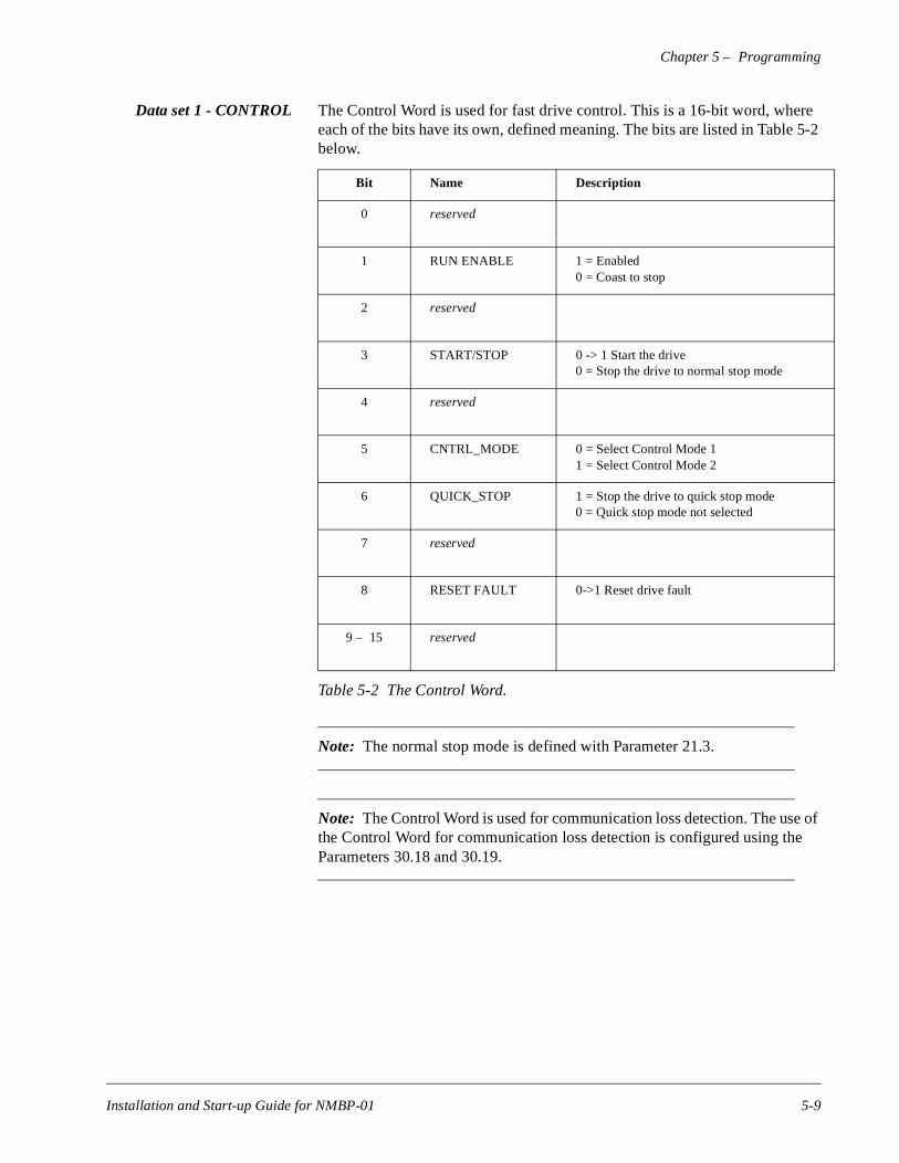
Data set 1 - CONTROL The Control Word is used for fast drive control. This is a 16-bit word, where each of the bits have its own, defined meaning. The bits are listed in Table 5-2 below.
Table 5-2 The Control Word.
Note: The normal stop mode is defined with Parameter 21.3.
Note: The Control Word is used for communication loss detection. The use of the Control Word for communication loss detection is configured using the Parameters 30.18 and 30.19.
Bit Name Description
0 reserved
1 RUN ENABLE 1 = Enabled0 = Coast to stop
2 reserved
3 START/STOP 0 -> 1 Start the drive0 = Stop the drive to normal stop mode
4 reserved
5 CNTRL_MODE 0 = Select Control Mode 11 = Select Control Mode 2
6 QUICK_STOP 1 = Stop the drive to quick stop mode0 = Quick stop mode not selected
7 reserved
8 RESET FAULT 0->1 Reset drive fault
9 – 15 reserved
Installation and Start-up Guide for NMBP-01 5-9

Chapter 5 – Programming
e set
Data set 2 - REFERENCE1
Used for receiving the Reference 1 value from the communication network.
This value is scaled so that a value of 20000 corresponds to the value set with Parameter 11.4 EXT REF1 MAXIMUM.
Data set 3 - REFERENCE2
Used for receiving the Reference 2 value from the communication network.
The signal source of REF2 must be set to COMM. MODULE and External control location 2 must be activated to use Reference 2 as the reference from the master.
The internal use of REF2 depends on the selected ACS 600 motor control mode and the selected Application Macro of the ACS 600.
• If the DTC (Direct Torque Control) mode and either the Factory, Hand/Auto or Sequential Control Macro are selected, REF2 is a speed reference. The integer 20000 corresponds to the value set with Parameter 11.8 EXT REF2 MAXIMUM (by default, 100%).
• If the DTC control mode and the Torque Control Macro are selected, REF2 is a torque reference. The integer 10000 corresponds to the valuwith Parameter 11.8 EXT REF2 MAXIMUM (by default, 100%).
• If the DTC control mode and the PID Control Macro are selected, REF2 is the PID controller reference. The integer 10000 corre-sponds to the value set with Parameter 11.8 EXT REF2 MAXIMUM (by default, 100%).
5-10 Installation and Start-up Guide for NMBP-01
Chapter 5 – Programming
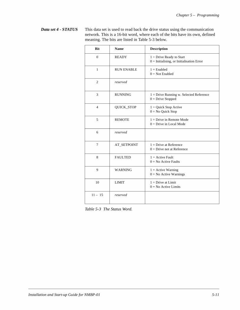
Data set 4 - STATUS This data set is used to read back the drive status using the communication network. This is a 16-bit word, where each of the bits have its own, defined meaning. The bits are listed in Table 5-3 below.
Table 5-3 The Status Word.
Bit Name Description
0 READY 1 = Drive Ready to Start0 = Initialising, or Initialisation Error
1 RUN ENABLE 1 = Enabled0 = Not Enabled
2 reserved
3 RUNNING 1 = Drive Running w. Selected Reference0 = Drive Stopped
4 QUICK_STOP 1 = Quick Stop Active0 = No Quick Stop
5 REMOTE 1 = Drive in Remote Mode0 = Drive in Local Mode
6 reserved
7 AT_SETPOINT 1 = Drive at Reference0 = Drive not at Reference
8 FAULTED 1 = Active Fault0 = No Active Faults
9 WARNING 1 = Active Warning0 = No Active Warnings
10 LIMIT 1 = Drive at Limit0 = No Active Limits
11 – 15 reserved
Installation and Start-up Guide for NMBP-01 5-11
Chapter 5 – Programming
Data set 5 - ACTUAL 1 This data set contains Actual value 1. This value is selected using Parameter 15.1. The possible selections are described in Parameter 15.1 ANALOGUE OUTPUT 1.
Data set 6 - ACTUAL 2 This data set contains Actual value 2. This value is selected using Parameter 15.6. The possible selections are described in Parameter 15.6 ANALOGUE OUTPUT 2.
CommunicationLoss Setup
To protect equipment and personnel, the drive in application must be config-ured properly to handle situations where communication is lost from the con-trolling system. The ACS 600 drive has two parameters which will define the action to be taken if communication is lost to the drive.
30.18 COMM FLT FUNC Defines what action is taken when the communication master is lost.
FAULTLoss of communication will generate a fault in the ACS 600 drive. The fault is recorded into the fault history, and shown on the panel. The drive stops according to the stop function set in Parameter 21.3 STOP FUNCTION.
NOThe loss of communication is ignored. No action is taken.
CONST SP 15There is a warning on the drive control panel, and on the Status Word. The drive will run at the speed defined in Parameter 12.16 CONST SPEED 15.
LAST SPEEDThere is a warning on the drive control panel, and on the Status Word. The drive will continue to operate at the last received speed. This value is the aver-age reference over the last 15 seconds before the loss of communication.
WARNING! If CONST SP 15 or LAST SPEED is selected, ensureit is safe to continue operation in case communication with theadapter module fails.
30.19 COMM FLTTIME OUT
Defines the maximum time allowed between writes to data set 1 (Control Word) from the master, before a communication loss is detected.
0.1 s – 60.0 s
5-12 Installation and Start-up Guide for NMBP-01
n
s on s is
us
od- one
– 8.
et-
Chapter 6 – Communication
This chapter describes the Modbus Plus communication on ACS 600 drives.
Introduction to Modbus Plus
Modbus Plus is a 1 MBit/s, transformer-coupled network. The transformer coupling isolates all the nodes galvanically from the network.
Modbus Plus is designed for Modicon PLCs, and the services closely corre-spond to the PLC architecture. The ACS 600 drive ‘ looks like’ a ModicoPLC on the network.
Program Paths Modbus Plus network always uses five address fields for addressing nodethe network. Unused ones must be set to zero. The purpose of these fielddevice-dependent.
Examples of addresses are:
• PLCs. Only one address, which is the node number on the Modbus Plnetwork
• Bridge/Mux. Two or three fields. First one is the node number on the Mbus Plus network. The second one is the serial port number. The thirdis the slave number if in network mode.
• ACS 600. Two fields. The first field is the node number on the ModbusPlus network. The second number is internal program path number 1
This multilevel addressing allows the user to build a large and extensive nwork, tying together individual segments with Bridges.
Installation and Start-up Guide for NMBP-01 6-1
Chapter 6 – Communication
is
bus
other
ove for
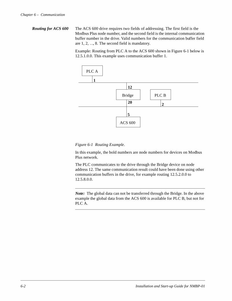
Routing for ACS 600 The ACS 600 drive requires two fields of addressing. The first field is the Modbus Plus node number, and the second field is the internal communication buffer number in the drive. Valid numbers for the communication buffer field are 1, 2, …, 8. The second field is mandatory.
Example: Routing from PLC A to the ACS 600 shown in Figure 6-1 below12.5.1.0.0. This example uses communication buffer 1.
Figure 6-1 Routing Example.
In this example, the bold numbers are node numbers for devices on ModPlus network.
The PLC communicates to the drive through the Bridge device on node address 12. The same communication result could have been done usingcommunication buffers in the drive, for example routing 12.5.2.0.0 to 12.5.8.0.0.
Note: The global data can not be transferred through the Bridge. In the abexample the global data from the ACS 600 is available for PLC B, but notPLC A.
PLC A
Bridge
ACS 600
1
12
20
5
PLC B
2
6-2 Installation and Start-up Guide for NMBP-01
Chapter 6 – Communication
mber, up.
Register Read and Write The ACS 600 has all the drive parameter and data set information mapped into a 4xxxx register area. This holding register area can be read from an external device, and an external device can modify the register values by writ-ing to them.
There are no setup parameters for mapping the data to the 4xxxx register. The mapping is pre-defined, and corresponds directly to the drive parameter grouping which is being used by the local control panel.
All parameters are available for both reading and writing. The parameter writes are verified for correct value, and for valid register addresses. Some parameters never allow writes (including actual values), some parameters allow write only when the drive is stopped (including setup variables), and some can be modified at any time (including actual reference values).
Register Mapping The drive parameters are mapped to the 4xxxx area so that:
• 40001 – 40099 are reserved for data sets
• 40101 – 40199 are reserved for the actual values
• 40201 – 40299 are reserved for group 2
• …
• 49901 – 49999 are reserved for the start-up data.
In this mapping, the thousands and hundreds correspond to the group nuwhile the tens and ones correspond to the parameter number within a gro
Installation and Start-up Guide for NMBP-01 6-3
Chapter 6 – Communication
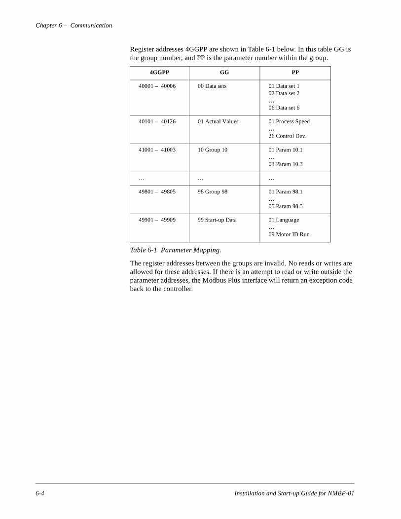
Register addresses 4GGPP are shown in Table 6-1 below. In this table GG is the group number, and PP is the parameter number within the group.
Table 6-1 Parameter Mapping.
The register addresses between the groups are invalid. No reads or writes are allowed for these addresses. If there is an attempt to read or write outside the parameter addresses, the Modbus Plus interface will return an exception code back to the controller.
4GGPP GG PP
40001 – 40006 00 Data sets 01 Data set 102 Data set 2…06 Data set 6
40101 – 40126 01 Actual Values 01 Process Speed…26 Control Dev.
41001 – 41003 10 Group 10 01 Param 10.1…03 Param 10.3
… … …
49801 – 49805 98 Group 98 01 Param 98.1…05 Param 98.5
49901 – 49909 99 Start-up Data 01 Language…09 Motor ID Run
6-4 Installation and Start-up Guide for NMBP-01
Chapter 6 – Communication
th (0
n eiv-
ee
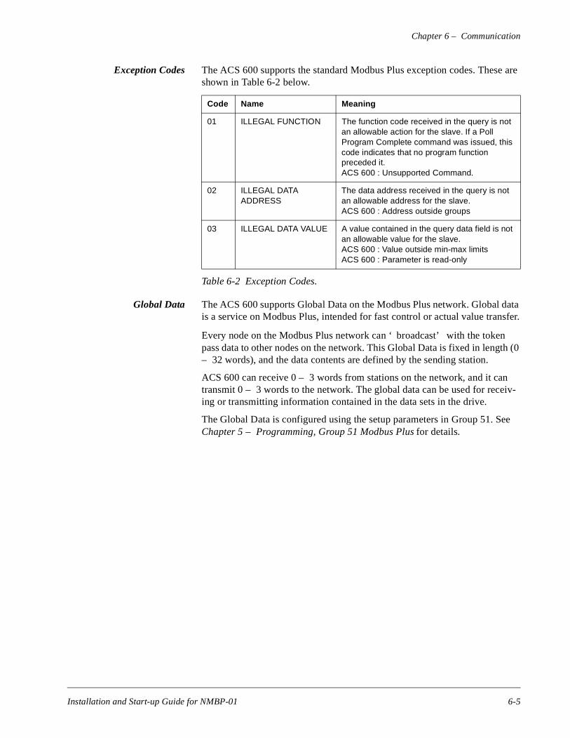
Exception Codes The ACS 600 supports the standard Modbus Plus exception codes. These are shown in Table 6-2 below.
Table 6-2 Exception Codes.
Global Data The ACS 600 supports Global Data on the Modbus Plus network. Global data is a service on Modbus Plus, intended for fast control or actual value transfer.
Every node on the Modbus Plus network can ‘ broadcast’ with the tokenpass data to other nodes on the network. This Global Data is fixed in leng– 32 words), and the data contents are defined by the sending station.
ACS 600 can receive 0 – 3 words from stations on the network, and it catransmit 0 – 3 words to the network. The global data can be used for recing or transmitting information contained in the data sets in the drive.
The Global Data is configured using the setup parameters in Group 51. SChapter 5 – Programming, Group 51 Modbus Plus for details.
Code Name Meaning
01 ILLEGAL FUNCTION The function code received in the query is not an allowable action for the slave. If a Poll Program Complete command was issued, this code indicates that no program function preceded it.ACS 600 : Unsupported Command.
02 ILLEGAL DATA ADDRESS
The data address received in the query is not an allowable address for the slave.ACS 600 : Address outside groups
03 ILLEGAL DATA VALUE A value contained in the query data field is not an allowable value for the slave.ACS 600 : Value outside min-max limitsACS 600 : Parameter is read-only
Installation and Start-up Guide for NMBP-01 6-5
Chapter 6 – Communication
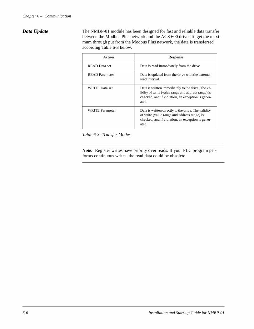
Data Update The NMBP-01 module has been designed for fast and reliable data transfer between the Modbus Plus network and the ACS 600 drive. To get the maxi-mum through put from the Modbus Plus network, the data is transferred according Table 6-3 below.
Table 6-3 Transfer Modes.
Note: Register writes have priority over reads. If your PLC program per-forms continuous writes, the read data could be obsolete.
Action Response
READ Data set Data is read immediately from the drive
READ Parameter Data is updated from the drive with the external read interval.
WRITE Data set Data is written immediately to the drive. The va-lidity of write (value range and address range) is checked, and if violation, an exception is gener-ated.
WRITE Parameter Data is written directly to the drive. The validity of write (value range and address range) is checked, and if violation, an exception is gener-ated.
6-6 Installation and Start-up Guide for NMBP-01
-01
ure
go
E
Chapter 7 – Fault Tracing
This chapter gives step-by-step diagnostics information for determining root causes and corrections to the most usual problems with the NMBP-01 Mod-ule.
This section is divided into different sections, and every chapter lists first the symptoms, then possible causes, and remedies for them.
Installation Problems Verify all the connections on the module:
• Modbus Plus cable is connected to the Modbus Plus terminal
• 24 V d.c. power is connected to the power terminal
• Fibre link cable is connected between the drive Channel 0 and the NMBP-01 Module
• Check that the fibre link connector colours match the drive and NMBPModule connector colours.
Drive Setup Group 51 is not shown on panel.
• Set Parameter 98.2 to YES (COMM MODULE)
The NMBP-01 is using default values.
• Verify that Parameter Group 51 is setup correctly. If so, press the configbutton on the NMBP-01 which causes the module to re-read its setup parameters.
Drive values can be read, but the control (Start/Stop or Reference) does not through.
• Check that the control location parameters are set to COMM. MODULfor the required operation.
• Check that the drive is in REMOTE control.
PLC Programming PLC ladder program is beyond ABB Drives support.
Installation and Start-up Guide for NMBP-01 7-1
Chapter 7 – Fault Tracing
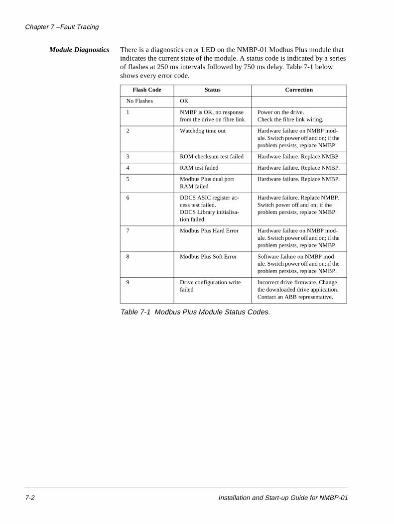
Module Diagnostics There is a diagnostics error LED on the NMBP-01 Modbus Plus module that indicates the current state of the module. A status code is indicated by a series of flashes at 250 ms intervals followed by 750 ms delay. Table 7-1 below shows every error code.
Table 7-1 Modbus Plus Module Status Codes.
Flash Code Status Correction
No Flashes OK
1 NMBP is OK, no response from the drive on fibre link
Power on the drive.Check the fibre link wiring.
2 Watchdog time out Hardware failure on NMBP mod-ule. Switch power off and on; if the problem persists, replace NMBP.
3 ROM checksum test failed Hardware failure. Replace NMBP.
4 RAM test failed Hardware failure. Replace NMBP.
5 Modbus Plus dual port RAM failed
Hardware failure. Replace NMBP.
6 DDCS ASIC register ac-cess test failed.DDCS Library initialisa-tion failed.
Hardware failure. Replace NMBP. Switch power off and on; if the problem persists, replace NMBP.
7 Modbus Plus Hard Error Hardware failure on NMBP mod-ule. Switch power off and on; if the problem persists, replace NMBP.
8 Modbus Plus Soft Error Software failure on NMBP mod-ule. Switch power off and on; if the problem persists, replace NMBP.
9 Drive configuration write failed
Incorrect drive firmware. Change the downloaded drive application. Contact an ABB representative.
7-2 Installation and Start-up Guide for NMBP-01
Chapter 7 – Fault Tracing
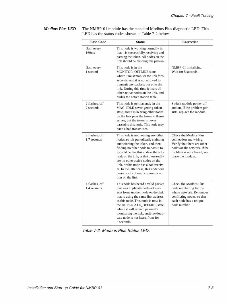
Modbus Plus LED The NMBP-01 module has the standard Modbus Plus diagnostic LED. This LED has the status codes shown in Table 7-2 below.
Table 7-2 Modbus Plus Status LED.
Flash Code Status Correction
flash every 160ms
This node is working normally in that it is successfully receiving and passing the token. All nodes on the link should be flashing this pattern.
flash every 1 second
This node is in the MONITOR_OFFLINE state, where it must monitor the link for 5 seconds, and it is not allowed to transmit any packets out onto the link. During this time it hears all other active nodes on the link, and builds the active station table.
NMBP-01 initialising.Wait for 5 seconds.
2 flashes, off 2 seconds
This node is permanently in the MAC_IDLE never-getting-token state, and it is hearing other nodes on the link pass the token to them-selves, but the token is never passed to this node. This node may have a bad transmitter.
Switch module power off and on. If the problem per-sists, replace the module.
3 flashes, off 1.7 seconds
This node is not hearing any other nodes, so it is periodically claiming and winning the token, and then finding no other node to pass it to. It could be that this node is the only node on the link, or that there really are no other active nodes on the link, or this node has a bad receiv-er. In the latter case, this node will periodically disrupt communica-tion on the link.
Check the Modbus Plus connection and wiring. Verify that there are other nodes on the network. If the problem is not cleared, re-place the module.
4 flashes, off 1.4 seconds
This node has heard a valid packet that was duplicate-node-address sent from another node on the link that is using the same link address as this node. This node is now in the DUPLICATE_OFFLINE state where it will remain passively monitoring the link, until the dupli-cate node is not heard from for 5 seconds.
Check the Modbus Plus node numbering for the whole network. Renumber conflicting nodes, so that each node has a unique node number.
Installation and Start-up Guide for NMBP-01 7-3
Chapter 7 – Fault Tracing
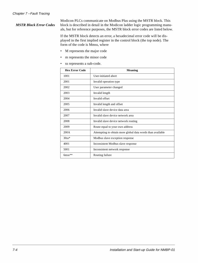
MSTR Block Error CodesModicon PLCs communicate on Modbus Plus using the MSTR block. This block is described in detail in the Modicon ladder logic programming manu-als, but for reference purposes, the MSTR block error codes are listed below.
If the MSTR block detects an error, a hexadecimal error code will be dis-played in the first implied register in the control block (the top node). The form of the code is Mmss, where
• M represents the major code
• m represents the minor code
• ss represents a sub-code.
Hex Error Code Meaning
1001 User-initiated abort
2001 Invalid operation type
2002 User parameter changed
2003 Invalid length
2004 Invalid offset
2005 Invalid length and offset
2006 Invalid slave device data area
2007 Invalid slave device network area
2008 Invalid slave device network routing
2009 Route equal to your own address
200A Attempting to obtain more global data words than available
30ss* Modbus slave exception response
4001 Inconsistent Modbus slave response
5001 Inconsistent network response
6mss** Routing failure
7-4 Installation and Start-up Guide for NMBP-01
Chapter 7 – Fault Tracing
e
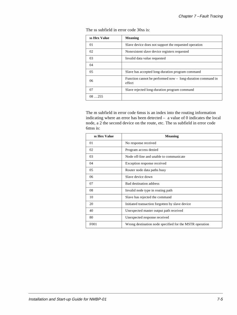
The ss subfield in error code 30ss is:
The m subfield in error code 6mss is an index into the routing information indicating where an error has been detected – a value of 0 indicates the local node, a 2 the second device on the route, etc. The ss subfield in error cod6mss is:
ss Hex Value Meaning
01 Slave device does not support the requested operation
02 Nonexistent slave device registers requested
03 Invalid data value requested
04
05 Slave has accepted long-duration program command
06Function cannot be performed now – long-duration command in effect
07 Slave rejected long-duration program command
08 … 255
ss Hex Value Meaning
01 No response received
02 Program access denied
03 Node off-line and unable to communicate
04 Exception response received
05 Router node data paths busy
06 Slave device down
07 Bad destination address
08 Invalid node type in routing path
10 Slave has rejected the command
20 Initiated transaction forgotten by slave device
40 Unexpected master output path received
80 Unexpected response received
F001 Wrong destination node specified for the MSTR operation
Installation and Start-up Guide for NMBP-01 7-5
Chapter 7 – Fault Tracing
ng
Hardware Failures The NMBP-01 module has a combined power and Watchdog LED. This LED is normally on. If the built-in watchdog ‘ kicks in’ , the power LED will go dim for half a second, and the NMBP-01 module will restart itself.
This restart can be caused by:
• Module failure. In this case the NMBP-01 Status LED will flash accordito error code 2. This is the only non-normal condition
• Pressing the configure button
• Loss of drive power
• Loss of fibre link connection between the NMBP-01 and the ACS 600 drive.
7-6 Installation and Start-up Guide for NMBP-01
/
Appendix A – Technical Data
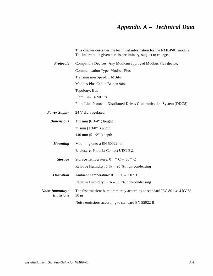
This chapter describes the technical information for the NMBP-01 module. The information given here is preliminary, subject to change.
Protocols Compatible Devices: Any Modicon approved Modbus Plus device.
Communication Type: Modbus Plus
Transmission Speed: 1 MBit/s
Modbus Plus Cable: Belden 9841
Topology: Bus
Fibre Link: 4 MBit/s
Fibre Link Protocol: Distributed Drives Communication System (DDCS)
Power Supply 24 V d.c. regulated
Dimensions 171 mm (6 3/4“ ) height
35 mm (1 3/8” ) width
140 mm (5 1/2” ) depth
Mounting Mounting onto a EN 50022 rail
Enclosure: Phoenix Contact UEG-EU.
Storage Storage Temperature: 0 ° C – 50 ° C
Relative Humidity: 5 % – 95 %, non-condensing
Operation Ambient Temperature: 0 ° C – 50 ° C
Relative Humidity: 5 % – 95 %, non-condensing
Noise Immunity /Emissions
The fast transient burst immunity according to standard IEC 801-4: 4 kV 550 ns.
Noise emissions according to standard EN 55022 B.
Installation and Start-up Guide for NMBP-01 A-1

Appendix A – Technical Data
This page is intentionally left blank.
A-2 Installation and Start-up Guide for NMBP-01
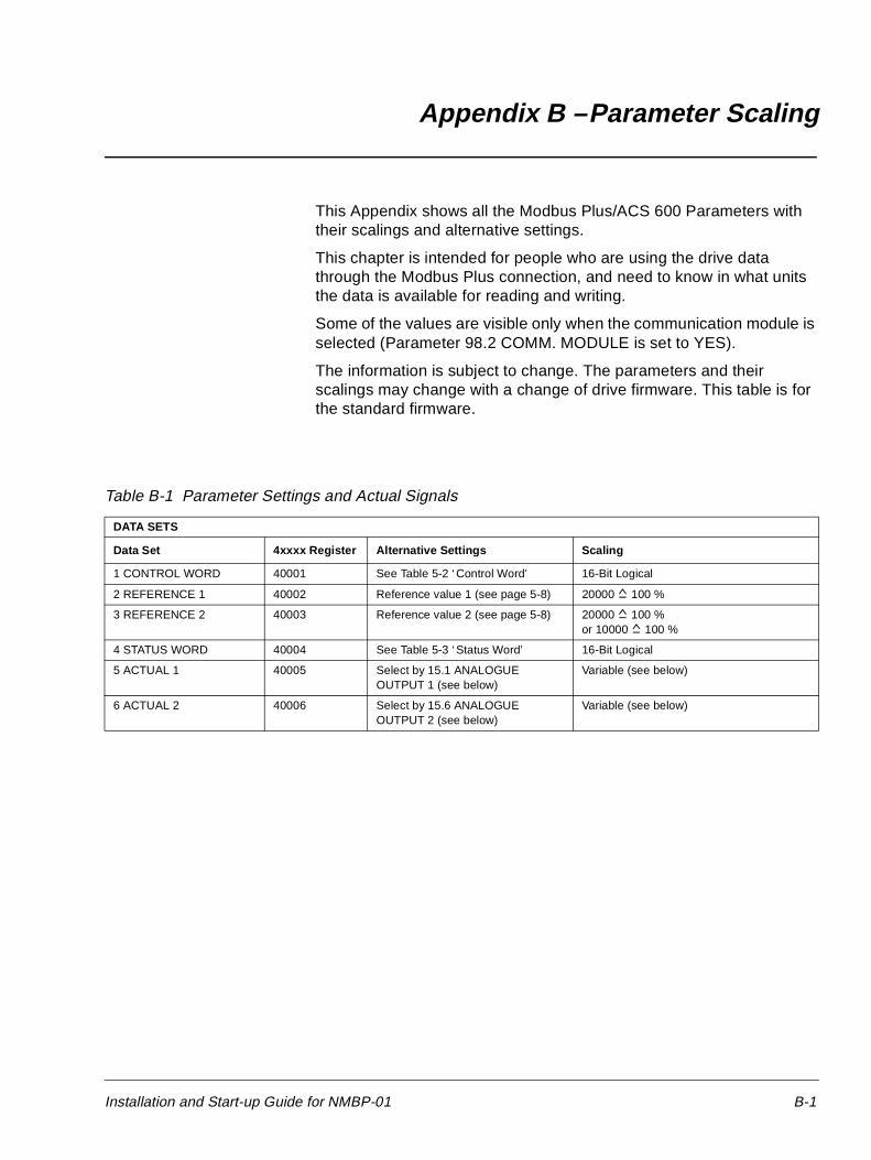
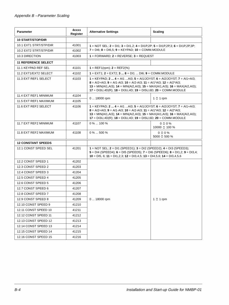
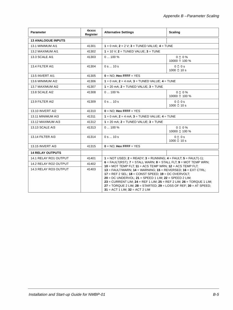
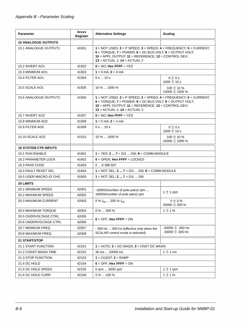
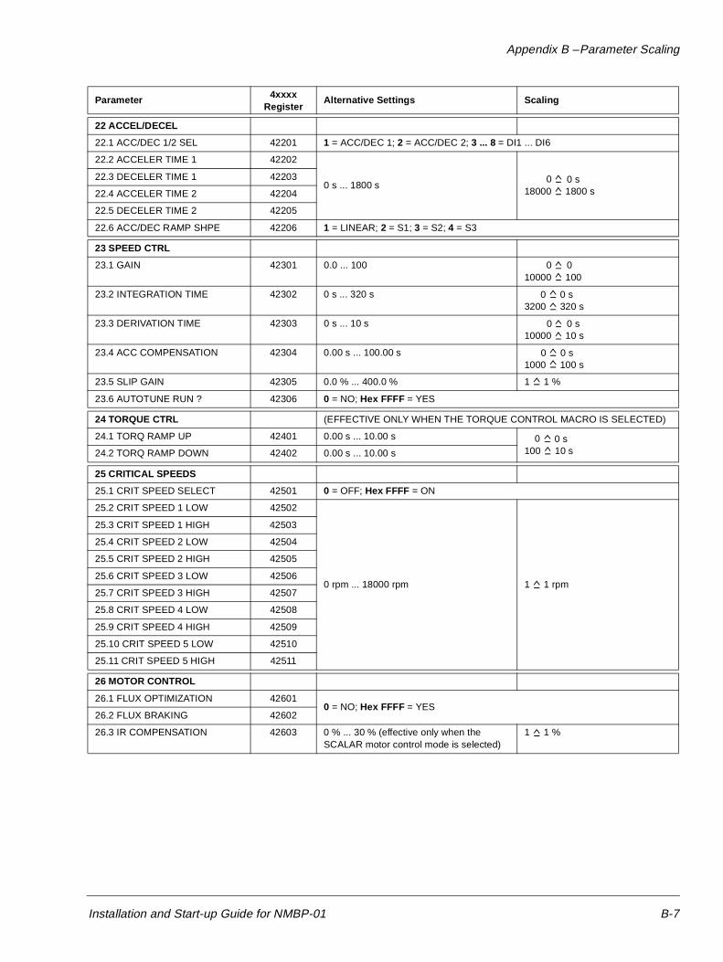
Appendix B – Parameter Scaling
This Appendix shows all the Modbus Plus/ACS 600 Parameters with their scalings and alternative settings.
This chapter is intended for people who are using the drive data through the Modbus Plus connection, and need to know in what units the data is available for reading and writing.
Some of the values are visible only when the communication module is selected (Parameter 98.2 COMM. MODULE is set to YES).
The information is subject to change. The parameters and their scalings may change with a change of drive firmware. This table is for the standard firmware.
Table B-1 Parameter Settings and Actual Signals
DATA SETS
Data Set 4xxxx Register Alternative Settings Scaling
1 CONTROL WORD 40001 See Table 5-2 ‘ Control Word’ 16-Bit Logical
2 REFERENCE 1 40002 Reference value 1 (see page 5-8) 20000 100 %
3 REFERENCE 2 40003 Reference value 2 (see page 5-8) 20000 100 %or 10000 100 %
4 STATUS WORD 40004 See Table 5-3 ‘ Status Word’ 16-Bit Logical
5 ACTUAL 1 40005 Select by 15.1 ANALOGUEOUTPUT 1 (see below)
Variable (see below)
6 ACTUAL 2 40006 Select by 15.6 ANALOGUEOUTPUT 2 (see below)
Variable (see below)
Installation and Start-up Guide for NMBP-01 B-1
Appendix B – Parameter Scaling
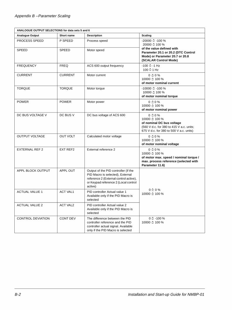
ANALOGUE OUTPUT SELECTIONS for data sets 5 and 6
Analogue Output Short name Description Scaling
PROCESS SPEED P SPEED Process speed -20000 -100 %
of the value defined withParameter 20.1 or 20.2 (DTC Control Mode) or Parameter 20.7 or 20.8 (SCALAR Control Mode)
SPEED SPEED Motor speed
FREQUENCY FREQ ACS 600 output frequency -100 -1 Hz
CURRENT CURRENT Motor current10000 100 %of motor nominal current
TORQUE TORQUE Motor torque -10000 -100 %
of motor nominal torque
POWER POWER Motor power10000 100 %of motor nominal power
DC BUS VOLTAGE V DC BUS V DC bus voltage of ACS 60010000 100 %of nominal DC bus voltage(560 V d.c. for 380 to 415 V a.c. units;675 V d.c. for 380 to 500 V a.c. units)
OUTPUT VOLTAGE OUT VOLT Calculated motor voltage10000 100 %of motor nominal voltage
EXTERNAL REF 2 EXT REF2 External reference 210000 100 %of motor max. speed / nominal torque / max. process reference (selected with Parameter 11.6)
APPL BLOCK OUTPUT APPL OUT Output of the PID controller (if the PID Macro is selected), External reference 2 (External control active), or Keypad reference 2 (Local control active)
10000 100 %ACTUAL VALUE 1 ACT VAL1 PID controller Actual value 1
Available only if the PID Macro is selected
ACTUAL VALUE 2 ACT VAL2 PID controller Actual value 2Available only if the PID Macro is selected
CONTROL DEVIATION CONT DEV The difference between the PID controller reference and the PID controller actual signal. Available only if the PID Macro is selected
10000 100 %
100 %20000
1 Hz100
0 0 %
100 %10000
0 0 %
0 0 %
0 0 %
0 0 %
0 0 %
0 -100 %
B-2 Installation and Start-up Guide for NMBP-01
Appendix B – Parameter Scaling
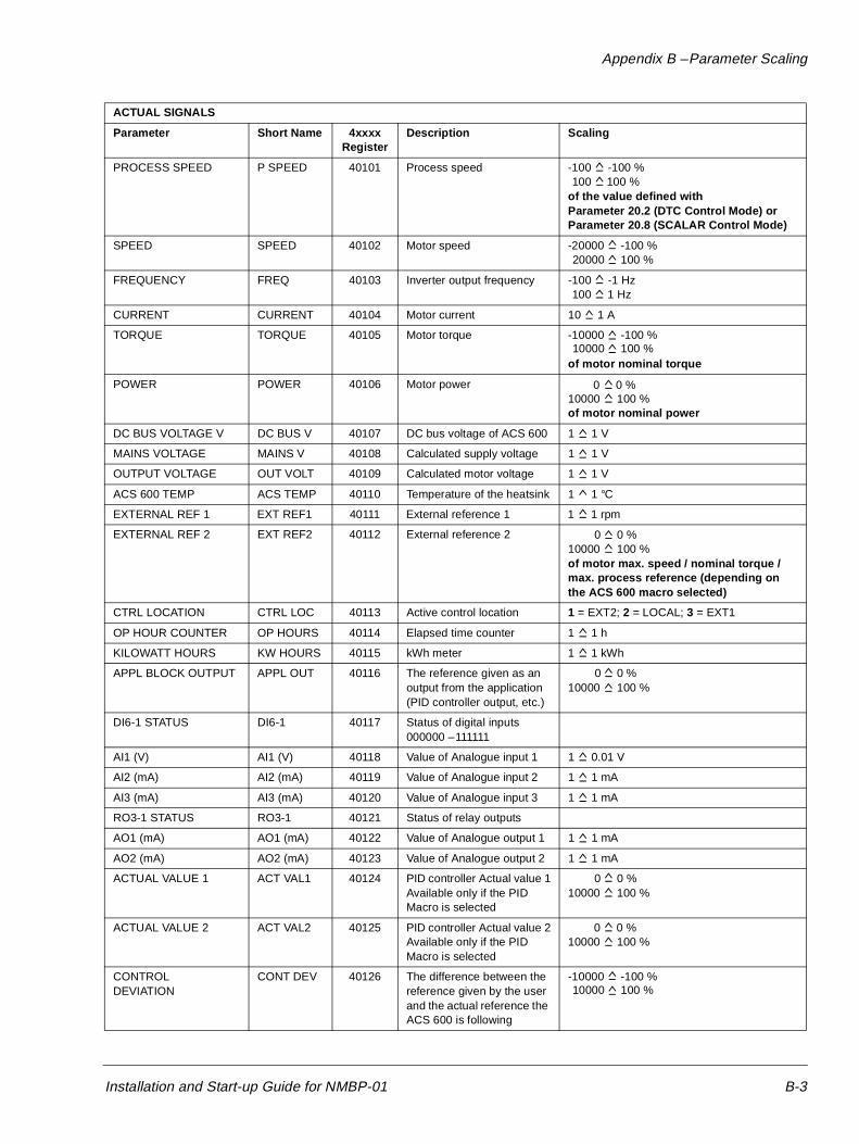
ACTUAL SIGNALS
Parameter Short Name 4xxxxRegister
Description Scaling
PROCESS SPEED P SPEED 40101 Process speed -100 -100 %
of the value defined withParameter 20.2 (DTC Control Mode) or Parameter 20.8 (SCALAR Control Mode)
SPEED SPEED 40102 Motor speed -20000 -100 %
FREQUENCY FREQ 40103 Inverter output frequency -100 -1 Hz
CURRENT CURRENT 40104 Motor current 10 1 A
TORQUE TORQUE 40105 Motor torque -10000 -100 %
of motor nominal torque
POWER POWER 40106 Motor power10000 100 %of motor nominal power
DC BUS VOLTAGE V DC BUS V 40107 DC bus voltage of ACS 600 1 1 V
MAINS VOLTAGE MAINS V 40108 Calculated supply voltage 1 1 V
OUTPUT VOLTAGE OUT VOLT 40109 Calculated motor voltage 1 1 V
ACS 600 TEMP ACS TEMP 40110 Temperature of the heatsink 1 1 °C
EXTERNAL REF 1 EXT REF1 40111 External reference 1 1 1 rpm
EXTERNAL REF 2 EXT REF2 40112 External reference 210000 100 %of motor max. speed / nominal torque / max. process reference (depending on the ACS 600 macro selected)
CTRL LOCATION CTRL LOC 40113 Active control location 1 = EXT2; 2 = LOCAL; 3 = EXT1
OP HOUR COUNTER OP HOURS 40114 Elapsed time counter 1 1 h
KILOWATT HOURS KW HOURS 40115 kWh meter 1 1 kWh
APPL BLOCK OUTPUT APPL OUT 40116 The reference given as an output from the application (PID controller output, etc.)
10000 100 %
DI6-1 STATUS DI6-1 40117 Status of digital inputs000000 – 111111
AI1 (V) AI1 (V) 40118 Value of Analogue input 1 1 0.01 V
AI2 (mA) AI2 (mA) 40119 Value of Analogue input 2 1 1 mA
AI3 (mA) AI3 (mA) 40120 Value of Analogue input 3 1 1 mA
RO3-1 STATUS RO3-1 40121 Status of relay outputs
AO1 (mA) AO1 (mA) 40122 Value of Analogue output 1 1 1 mA
AO2 (mA) AO2 (mA) 40123 Value of Analogue output 2 1 1 mA
ACTUAL VALUE 1 ACT VAL1 40124 PID controller Actual value 1Available only if the PID Macro is selected
10000 100 %
ACTUAL VALUE 2 ACT VAL2 40125 PID controller Actual value 2Available only if the PID Macro is selected
10000 100 %
CONTROLDEVIATION
CONT DEV 40126 The difference between the reference given by the user and the actual reference the ACS 600 is following
-10000 -100 %
100 %100
100 %20000
1 Hz100
10000 100 %
0 0 %
0 0 %
0 0 %
0 %0
0 %0
10000 100 %
Installation and Start-up Guide for NMBP-01 B-3
Appendix B – Parameter Scaling
Parameter 4xxxx Register
Alternative Settings Scaling
10 START/STOP/DIR
10.1 EXT1 STRT/STP/DIR 41001 1 = NOT SEL; 2 = DI1; 3 = DI1,2; 4 = DI1P,2P; 5 = DI1P,2P,3; 6 = DI1P,2P,3P;7 = DI6; 8 = DI6,5; 9 = KEYPAD; 10 = COMM.MODULE10.2 EXT2 STRT/STP/DIR 41002
10.3 DIRECTION 41003 1 = FORWARD; 2 = REVERSE; 3 = REQUEST
11 REFERENCE SELECT
11.1 KEYPAD REF SEL 41101 1 = REF1(rpm); 2 = REF2(%)
11.2 EXT1/EXT2 SELECT 41102 1 = EXT1; 2 = EXT2; 3 ... 8 = DI1 ... DI6; 9 = COMM.MODULE
11.3 EXT REF1 SELECT 41103 1 = KEYPAD; 2 ... 4 = AI1 ...AI3; 5 = AI1/JOYST; 6 = AI2/JOYST; 7 = AI1+AI3;8 = AI2+AI3; 9 = AI1-AI3; 10 = AI2-AI3; 11 = AI1*AI3; 12 = AI2*AI3;13 = MIN(AI1,AI3); 14 = MIN(AI2,AI3); 15 = MAX(AI1,AI3); 16 = MAX(AI2,AI3); 17 = DI3U,4D(R); 18 = DI3U,4D; 19 = DI5U,6D; 20 = COMM.MODULE
11.4 EXT REF1 MINIMUM 411040 ... 18000 rpm 1 1 rpm
11.5 EXT REF1 MAXIMUM 41105
11.6 EXT REF2 SELECT 41106 1 = KEYPAD; 2 ... 4 = AI1 ...AI3; 5 = AI1/JOYST; 6 = AI2/JOYST; 7 = AI1+AI3;8 = AI2+AI3; 9 = AI1-AI3; 10 = AI2-AI3; 11 = AI1*AI3; 12 = AI2*AI3;13 = MIN(AI1,AI3); 14 = MIN(AI2,AI3); 15 = MAX(AI1,AI3); 16 = MAX(AI2,AI3);17 = DI3U,4D(R); 18 = DI3U,4D; 19 = DI5U,6D; 20 = COMM.MODULE
11.7 EXT REF2 MINIMUM 41107 0 % ... 100 %10000 100 %
11.8 EXT REF2 MAXIMUM 41108 0 % ... 500 %5000 500 %
12 CONSTANT SPEEDS
12.1 CONST SPEED SEL 41201 1 = NOT SEL; 2 = DI1 (SPEED1); 3 = DI2 (SPEED2); 4 = DI3 (SPEED3); 5 = DI4 (SPEED4); 6 = DI5 (SPEED5); 7 = DI6 (SPEED6); 8 = DI1,2; 9 = DI3,4; 10 = DI5, 6; 11 = DI1,2,3; 12 = DI3,4,5; 13 = DI4,5,6; 14 = DI3,4,5,6
12.2 CONST SPEED 1 41202
0 ... 18000 rpm 1 1 rpm
12.3 CONST SPEED 2 41203
12.4 CONST SPEED 3 41204
12.5 CONST SPEED 4 41205
12.6 CONST SPEED 5 41206
12.7 CONST SPEED 6 41207
12.8 CONST SPEED 7 41208
12.9 CONST SPEED 8 41209
12.10 CONST SPEED 9 41210
12.11 CONST SPEED 10 41211
12.12 CONST SPEED 11 41212
12.13 CONST SPEED 12 41213
12.14 CONST SPEED 13 41214
12.15 CONST SPEED 14 41215
12.16 CONST SPEED 15 41216
0 0 %
0 0 %
B-4 Installation and Start-up Guide for NMBP-01
Appendix B – Parameter Scaling
13 ANALOGUE INPUTS
13.1 MINIMUM AI1 41301 1 = 0 mA; 2 = 2 V; 3 = TUNED VALUE; 4 = TUNE
13.2 MAXIMUM AI1 41302 1 = 10 V; 2 = TUNED VALUE; 3 = TUNE
13.3 SCALE AI1 41303 0 ... 100 %10000 100 %
13.4 FILTER AI1 41304 0 s ... 10 s1000 10 s
13.5 INVERT AI1 41305 0 = NO; Hex FFFF = YES
13.6 MINIMUM AI2 41306 1 = 0 mA; 2 = 4 mA; 3 = TUNED VALUE; 4 = TUNE
13.7 MAXIMUM AI2 41307 1 = 20 mA; 2 = TUNED VALUE; 3 = TUNE
13.8 SCALE AI2 41308 0 ... 100 %10000 100 %
13.9 FILTER AI2 41309 0 s ... 10 s1000 10 s
13.10 INVERT AI2 41310 0 = NO; Hex FFFF = YES
13.11 MINIMUM AI3 41311 1 = 0 mA; 2 = 4 mA; 3 = TUNED VALUE; 4 = TUNE
13.12 MAXIMUM AI3 41312 1 = 20 mA; 2 = TUNED VALUE; 3 = TUNE
13.13 SCALE AI3 41313 0 ... 100 %10000 100 %
13.14 FILTER AI3 41314 0 s ... 10 s1000 10 s
13.15 INVERT AI3 41315 0 = NO; Hex FFFF = YES
14 RELAY OUTPUTS
14.1 RELAY RO1 OUTPUT 41401 1 = NOT USED; 2 = READY; 3 = RUNNING; 4 = FAULT; 5 = FAULT(-1);6 = FAULT(RST); 7 = STALL WARN; 8 = STALL FLT; 9 = MOT TEMP WRN;10 = MOT TEMP FLT; 11 = ACS TEMP WRN; 12 = ACS TEMP FLT;13 = FAULT/WARN; 14 = WARNING; 15 = REVERSED; 16 = EXT CTRL;17 = REF 2 SEL; 18 = CONST SPEED; 19 = DC OVERVOLT; 20 = DC UNDERVOL; 21 = SPEED 1 LIM; 22 = SPEED 2 LIM;23 = CURRENT LIM; 24 = REF 1 LIM; 25 = REF 2 LIM; 26 = TORQUE 1 LIM;27 = TORQUE 2 LIM; 28 = STARTED; 29 = LOSS OF REF; 30 = AT SPEED;31 = ACT 1 LIM; 32 = ACT 2 LIM
14.2 RELAY RO2 OUTPUT 41402
14.3 RELAY RO3 OUTPUT 41403
Parameter 4xxxx Register
Alternative Settings Scaling
0 0 %
0 0 s
0 0 %
0 0 s
0 0 %
0 0 s
Installation and Start-up Guide for NMBP-01 B-5
Appendix B – Parameter Scaling
15 ANALOGUE OUTPUTS
15.1 ANALOGUE OUTPUT1 41501 1 = NOT USED; 2 = P SPEED; 3 = SPEED; 4 = FREQUENCY; 5 = CURRENT;6 = TORQUE; 7 = POWER; 8 = DC BUS VOLT; 9 = OUTPUT VOLT; 10 = APPL OUTPUT; 11 = REFERENCE; 12 = CONTROL DEV; 13 = ACTUAL 1; 14 = ACTUAL 2
15.2 INVERT AO1 41502 0 = NO; Hex FFFF = YES
15.3 MINIMUM AO1 41503 1 = 0 mA; 2 = 4 mA
15.4 FILTER AO1 41504 0 s ... 10 s1000 10 s
15.5 SCALE AO1 41505 10 % ... 1000 %10000 1000 %
15.6 ANALOGUE OUTPUT2 41506 1 = NOT USED; 2 = P SPEED; 3 = SPEED; 4 = FREQUENCY; 5 = CURRENT;6 = TORQUE; 7 = POWER; 8 = DC BUS VOLT; 9 = OUTPUT VOLT; 10 = APPL OUTPUT; 11 = REFERENCE; 12 = CONTROL DEV; 13 = ACTUAL 1; 14 = ACTUAL 2
15.7 INVERT AO2 41507 0 = NO; Hex FFFF = YES
15.8 MINIMUM AO2 41508 1 = 0 mA; 2 = 4 mA
15.9 FILTER AO2 41509 0 s ... 10 s1000 10 s
15.10 SCALE AO2 41510 10 % ... 1000 %10000 1000 %
16 SYSTEM CTR INPUTS
16.1 RUN ENABLE 41601 1 = YES; 2 ... 7 = DI1 ... DI6; 8 = COMM.MODULE
16.2 PARAMETER LOCK 41602 0 = OPEN; Hex FFFF = LOCKED
16.3 PASS CODE 41603 0 ... 8 388 607
16.4 FAULT RESET SEL 41604 1 = NOT SEL; 2 ... 7 = DI1 ... DI6; 8 = COMM.MODULE
16.5 USER MACRO IO CHG 41605 1 = NOT SEL; 2 ... 7 = DI1 ... DI6
20 LIMITS
20.1 MINIMUM SPEED 42001 -18000/(number of pole pairs) rpm ... 18000/(number of pole pairs) rpm
1 1 rpm20.2 MAXIMUM SPEED 42002
20.3 MAXIMUM CURRENT 42003 0 % Ihd ... 200 % Ihd 20000 200 %
20.4 MAXIMUM TORQUE 42004 0 % ... 300 % 1 1 %
20.5 OVERVOLTAGE CTRL 420050 = OFF; Hex FFFF = ON
20.6 UNDERVOLTAGE CTRL 42006
20.7 MINIMUM FREQ 42007 - 300 Hz ... 300 Hz (effective only when the SCALAR control mode is selected)
-30000 -300 Hz
20.8 MAXIMUM FREQ 42008
21 START/STOP
21.1 START FUNCTION 42101 1 = AUTO; 2 = DC MAGN; 3 = CNST DC MAGN
21.2 CONST MAGN TIME 42102 30 ms ... 10000 ms 1 1 ms
21.3 STOP FUNCTION 42103 1 = COAST; 2 = RAMP
21.4 DC HOLD 42104 0 = OFF; Hex FFFF = ON
21.5 DC HOLD SPEED 42105 0 rpm ... 3000 rpm 1 1 rpm
21.6 DC HOLD CURR 42106 0 % ... 100 % 1 1 %
Parameter 4xxxx Register
Alternative Settings Scaling
0 0 s
100 10 %
0 0 s
100 10 %
0 0 %
300 Hz30000
B-6 Installation and Start-up Guide for NMBP-01
Appendix B – Parameter Scaling
22 ACCEL/DECEL
22.1 ACC/DEC 1/2 SEL 42201 1 = ACC/DEC 1; 2 = ACC/DEC 2; 3 ... 8 = DI1 ... DI6
22.2 ACCELER TIME 1 42202
0 s ... 1800 s18000 1800 s
22.3 DECELER TIME 1 42203
22.4 ACCELER TIME 2 42204
22.5 DECELER TIME 2 42205
22.6 ACC/DEC RAMP SHPE 42206 1 = LINEAR; 2 = S1; 3 = S2; 4 = S3
23 SPEED CTRL
23.1 GAIN 42301 0.0 ... 10010000 100
23.2 INTEGRATION TIME 42302 0 s ... 320 s3200 320 s
23.3 DERIVATION TIME 42303 0 s ... 10 s10000 10 s
23.4 ACC COMPENSATION 42304 0.00 s ... 100.00 s1000 100 s
23.5 SLIP GAIN 42305 0.0 % ... 400.0 % 1 1 %
23.6 AUTOTUNE RUN ? 42306 0 = NO; Hex FFFF = YES
24 TORQUE CTRL (EFFECTIVE ONLY WHEN THE TORQUE CONTROL MACRO IS SELECTED)
24.1 TORQ RAMP UP 42401 0.00 s ... 10.00 s
100 10 s24.2 TORQ RAMP DOWN 42402 0.00 s ... 10.00 s
25 CRITICAL SPEEDS
25.1 CRIT SPEED SELECT 42501 0 = OFF; Hex FFFF = ON
25.2 CRIT SPEED 1 LOW 42502
0 rpm ... 18000 rpm 1 1 rpm
25.3 CRIT SPEED 1 HIGH 42503
25.4 CRIT SPEED 2 LOW 42504
25.5 CRIT SPEED 2 HIGH 42505
25.6 CRIT SPEED 3 LOW 42506
25.7 CRIT SPEED 3 HIGH 42507
25.8 CRIT SPEED 4 LOW 42508
25.9 CRIT SPEED 4 HIGH 42509
25.10 CRIT SPEED 5 LOW 42510
25.11 CRIT SPEED 5 HIGH 42511
26 MOTOR CONTROL
26.1 FLUX OPTIMIZATION 426010 = NO; Hex FFFF = YES
26.2 FLUX BRAKING 42602
26.3 IR COMPENSATION 42603 0 % ... 30 % (effective only when the SCALAR motor control mode is selected)
1 1 %
Parameter 4xxxx Register
Alternative Settings Scaling
0 s0
00
0 s0
0 s0
0 s0
0 s0
Installation and Start-up Guide for NMBP-01 B-7
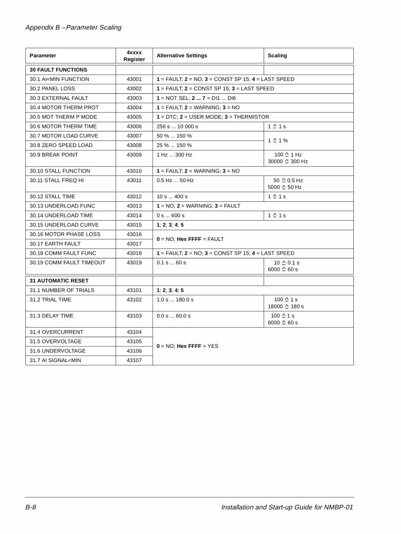
Appendix B – Parameter Scaling
30 FAULT FUNCTIONS
30.1 AI<MIN FUNCTION 43001 1 = FAULT; 2 = NO; 3 = CONST SP 15; 4 = LAST SPEED
30.2 PANEL LOSS 43002 1 = FAULT; 2 = CONST SP 15; 3 = LAST SPEED
30.3 EXTERNAL FAULT 43003 1 = NOT SEL; 2 ... 7 = DI1 ... DI6
30.4 MOTOR THERM PROT 43004 1 = FAULT; 2 = WARNING; 3 = NO
30.5 MOT THERM P MODE 43005 1 = DTC; 2 = USER MODE; 3 = THERMISTOR
30.6 MOTOR THERM TIME 43006 256 s ... 10 000 s 1 1 s
30.7 MOTOR LOAD CURVE 43007 50 % ... 150 %1 1 %
30.8 ZERO SPEED LOAD 43008 25 % ... 150 %
30.9 BREAK POINT 43009 1 Hz ... 300 Hz30000 300 Hz
30.10 STALL FUNCTION 43010 1 = FAULT; 2 = WARNING; 3 = NO
30.11 STALL FREQ HI 43011 0.5 Hz ... 50 Hz5000 50 Hz
30.12 STALL TIME 43012 10 s ... 400 s 1 1 s
30.13 UNDERLOAD FUNC 43013 1 = NO; 2 = WARNING; 3 = FAULT
30.14 UNDERLOAD TIME 43014 0 s ... 600 s 1 1 s
30.15 UNDERLOAD CURVE 43015 1; 2; 3; 4; 5
30.16 MOTOR PHASE LOSS 430160 = NO; Hex FFFF = FAULT
30.17 EARTH FAULT 43017
30.18 COMM FAULT FUNC 43018 1 = FAULT; 2 = NO; 3 = CONST SP 15; 4 = LAST SPEED
30.19 COMM FAULT TIMEOUT 43019 0.1 s ... 60 s6000 60 s
31 AUTOMATIC RESET
31.1 NUMBER OF TRIALS 43101 1; 2; 3; 4; 5
31.2 TRIAL TIME 43102 1.0 s ... 180.0 s18000 180 s
31.3 DELAY TIME 43103 0.0 s ... 60.0 s6000 60 s
31.4 OVERCURRENT 43104
0 = NO; Hex FFFF = YES 31.5 OVERVOLTAGE 43105
31.6 UNDERVOLTAGE 43106
31.7 AI SIGNAL<MIN 43107
Parameter 4xxxx Register
Alternative Settings Scaling
1 Hz100
0.5 Hz50
0.1 s10
1 s100
1 s100
B-8 Installation and Start-up Guide for NMBP-01
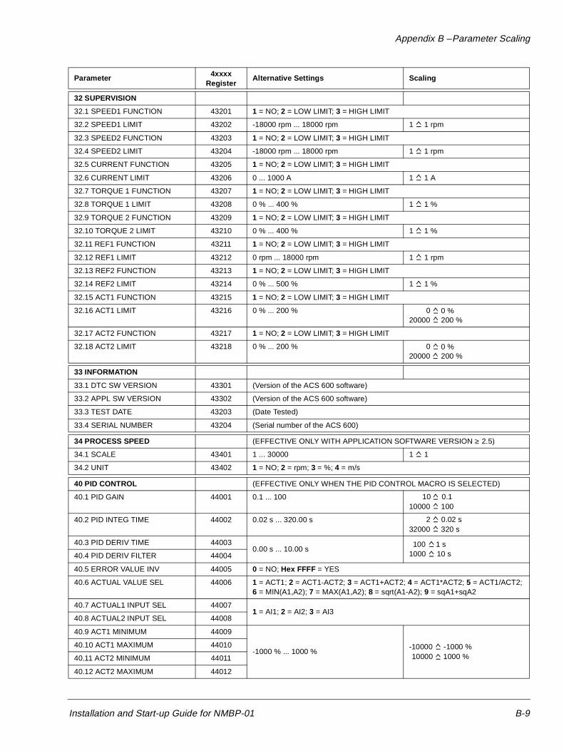
Appendix B – Parameter Scaling
32 SUPERVISION
32.1 SPEED1 FUNCTION 43201 1 = NO; 2 = LOW LIMIT; 3 = HIGH LIMIT
32.2 SPEED1 LIMIT 43202 -18000 rpm ... 18000 rpm 1 1 rpm
32.3 SPEED2 FUNCTION 43203 1 = NO; 2 = LOW LIMIT; 3 = HIGH LIMIT
32.4 SPEED2 LIMIT 43204 -18000 rpm ... 18000 rpm 1 1 rpm
32.5 CURRENT FUNCTION 43205 1 = NO; 2 = LOW LIMIT; 3 = HIGH LIMIT
32.6 CURRENT LIMIT 43206 0 ... 1000 A 1 1 A
32.7 TORQUE 1 FUNCTION 43207 1 = NO; 2 = LOW LIMIT; 3 = HIGH LIMIT
32.8 TORQUE 1 LIMIT 43208 0 % ... 400 % 1 1 %
32.9 TORQUE 2 FUNCTION 43209 1 = NO; 2 = LOW LIMIT; 3 = HIGH LIMIT
32.10 TORQUE 2 LIMIT 43210 0 % ... 400 % 1 1 %
32.11 REF1 FUNCTION 43211 1 = NO; 2 = LOW LIMIT; 3 = HIGH LIMIT
32.12 REF1 LIMIT 43212 0 rpm ... 18000 rpm 1 1 rpm
32.13 REF2 FUNCTION 43213 1 = NO; 2 = LOW LIMIT; 3 = HIGH LIMIT
32.14 REF2 LIMIT 43214 0 % ... 500 % 1 1 %
32.15 ACT1 FUNCTION 43215 1 = NO; 2 = LOW LIMIT; 3 = HIGH LIMIT
32.16 ACT1 LIMIT 43216 0 % ... 200 %20000 200 %
32.17 ACT2 FUNCTION 43217 1 = NO; 2 = LOW LIMIT; 3 = HIGH LIMIT
32.18 ACT2 LIMIT 43218 0 % ... 200 %20000 200 %
33 INFORMATION
33.1 DTC SW VERSION 43301 (Version of the ACS 600 software)
33.2 APPL SW VERSION 43302 (Version of the ACS 600 software)
33.3 TEST DATE 43203 (Date Tested)
33.4 SERIAL NUMBER 43204 (Serial number of the ACS 600)
34 PROCESS SPEED (EFFECTIVE ONLY WITH APPLICATION SOFTWARE VERSION ≥ 2.5)
34.1 SCALE 43401 1 ... 30000 1 1
34.2 UNIT 43402 1 = NO; 2 = rpm; 3 = %; 4 = m/s
40 PID CONTROL (EFFECTIVE ONLY WHEN THE PID CONTROL MACRO IS SELECTED)
40.1 PID GAIN 44001 0.1 ... 10010000 100
40.2 PID INTEG TIME 44002 0.02 s ... 320.00 s32000 320 s
40.3 PID DERIV TIME 440030.00 s ... 10.00 s
1000 10 s40.4 PID DERIV FILTER 44004
40.5 ERROR VALUE INV 44005 0 = NO; Hex FFFF = YES
40.6 ACTUAL VALUE SEL 44006 1 = ACT1; 2 = ACT1-ACT2; 3 = ACT1+ACT2; 4 = ACT1*ACT2; 5 = ACT1/ACT2;6 = MIN(A1,A2); 7 = MAX(A1,A2); 8 = sqrt(A1-A2); 9 = sqA1+sqA2
40.7 ACTUAL1 INPUT SEL 440071 = AI1; 2 = AI2; 3 = AI3
40.8 ACTUAL2 INPUT SEL 44008
40.9 ACT1 MINIMUM 44009
-1000 % ... 1000 %-10000 -1000 %40.10 ACT1 MAXIMUM 44010
40.11 ACT2 MINIMUM 44011
40.12 ACT2 MAXIMUM 44012
Parameter 4xxxx Register
Alternative Settings Scaling
0 %0
0 %0
0.110
0.02 s2
1 s100
1000 %10000
Installation and Start-up Guide for NMBP-01 B-9
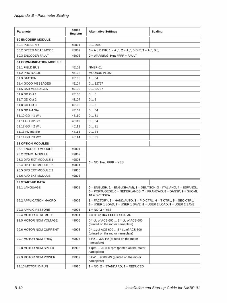
Appendix B – Parameter Scaling
50 ENCODER MODULE
50.1 PULSE NR 45001 0 ... 2999
50.2 SPEED MEAS MODE 45002 0 = A -- B DIR; 1 = A -
--; 2 = A -
-- B DIR; 3 = A -
-- B -
--
50.3 ENCODER FAULT 45003 0 = WARNING; Hex FFFF = FAULT
51 COMMUNICATION MODULE
51.1 FIELD BUS 45101 NMBP-01
51.2 PROTOCOL 45102 MODBUS PLUS
51.3 STATION 45103 1 ... 64
51.4 GOOD MESSAGES 45104 0 ... 32767
51.5 BAD MESSAGES 45105 0 ... 32767
51.6 GD Out 1 45106 0 ... 6
51.7 GD Out 2 45107 0 ... 6
51.8 GD Out 3 45108 0 ... 6
51.9 GD In1 Stn 45109 0 ... 64
51.10 GD In1 Wrd 45110 0 ... 31
51.11 GD In2 Stn 45111 0 ... 64
51.12 GD In2 Wrd 45112 0 ... 31
51.13 FD In3 Stn 45113 0 ... 64
51.14 GD In3 Wrd 45114 0 ... 31
98 OPTION MODULES
98.1 ENCODER MODULE 49801
0 = NO; Hex FFFF = YES
98.2 COMM. MODULE 49802
98.3 DI/O EXT MODULE 1 49803
98.4 DI/O EXT MODULE 2 49804
98.5 DI/O EXT MODULE 3 49805
98.6 AI/O EXT MODULE 49806
99 START-UP DATA
99.1 LANGUAGE 49901 0 = ENGLISH; 1 = ENGLISH(AM); 2 = DEUTSCH; 3 = ITALIANO; 4 = ESPANOL;5 = PORTUGESE; 6 = NEDERLANDS; 7 = FRANCAIS; 8 = DANSK; 9 = SUOMI;10 = SVENSKA
99.2 APPLICATION MACRO 49902 1 = FACTORY; 2 = HAND/AUTO; 3 = PID CTRL; 4 = T CTRL; 5 = SEQ CTRL;6 = USER 1 LOAD; 7 = USER 1 SAVE; 8 = USER 2 LOAD; 9 = USER 2 SAVE
99.3 APPLIC RESTORE 49903 1 = NO; 2 = YES
99.4 MOTOR CTRL MODE 49904 0 = DTC; Hex FFFF = SCALAR
99.5 MOTOR NOM VOLTAGE 49905 0 * UN of ACS 600 ... 2 * UN of ACS 600 (printed on the motor nameplate)
99.6 MOTOR NOM CURRENT 49906 0 * Ihd of ACS 600 ... 3 * Ihd of ACS 600 (printed on the motor nameplate)
99.7 MOTOR NOM FREQ 49907 8 Hz ... 300 Hz (printed on the motor nameplate)
99.8 MOTOR NOM SPEED 49908 1 rpm ... 20 000 rpm (printed on the motor nameplate)
99.9 MOTOR NOM POWER 49909 0 kW ... 9000 kW (printed on the motor nameplate)
99.10 MOTOR ID RUN 49910 1 = NO; 2 = STANDARD; 3 = REDUCED
Parameter 4xxxx Register
Alternative Settings Scaling
B-10 Installation and Start-up Guide for NMBP-01
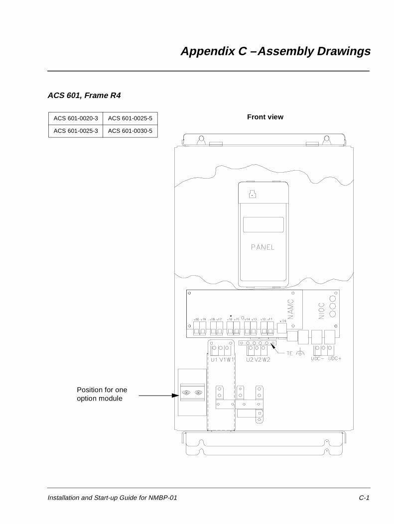
Appendix C – Assembly Drawings
ACS 601, Frame R4
ACS 601-0020-3 ACS 601-0025-5
ACS 601-0025-3 ACS 601-0030-5
Position for one option module
Front view
Installation and Start-up Guide for NMBP-01 C-1
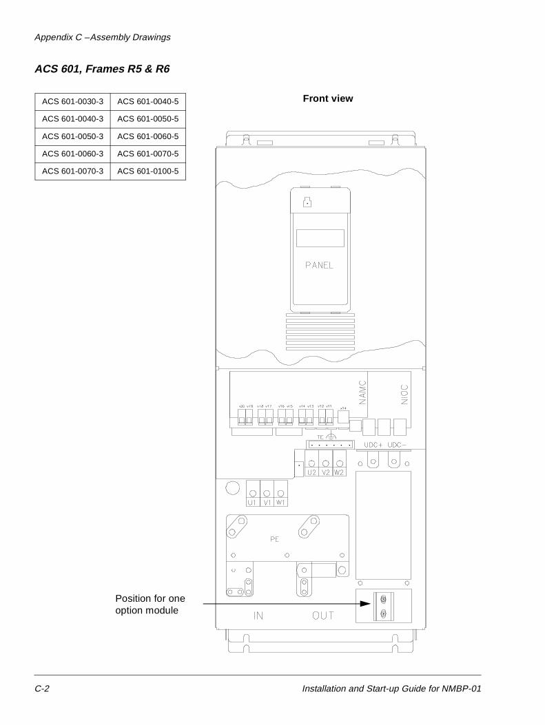
Appendix C – Assembly Drawings
ACS 601, Frames R5 & R6
ACS 601-0030-3 ACS 601-0040-5
ACS 601-0040-3 ACS 601-0050-5
ACS 601-0050-3 ACS 601-0060-5
ACS 601-0060-3 ACS 601-0070-5
ACS 601-0070-3 ACS 601-0100-5
Position for one option module
Front view
C-2 Installation and Start-up Guide for NMBP-01
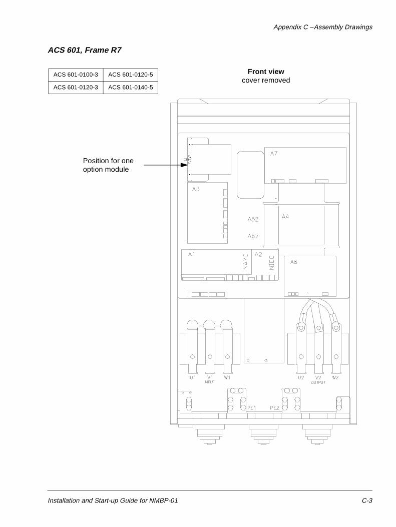
Appendix C – Assembly Drawings
ACS 601, Frame R7
ACS 601-0100-3 ACS 601-0120-5
ACS 601-0120-3 ACS 601-0140-5
Position for one option module
Front viewcover removed
Installation and Start-up Guide for NMBP-01 C-3

Appendix C – Assembly Drawings
ACS 603, Frame R7
ACS 603-0100-3 ACS 603-0120-5
ACS 603-0120-3 ACS 603-0140-5
Position for one option module
Front viewdoor open
converter unit cover removed
C-4 Installation and Start-up Guide for NMBP-01
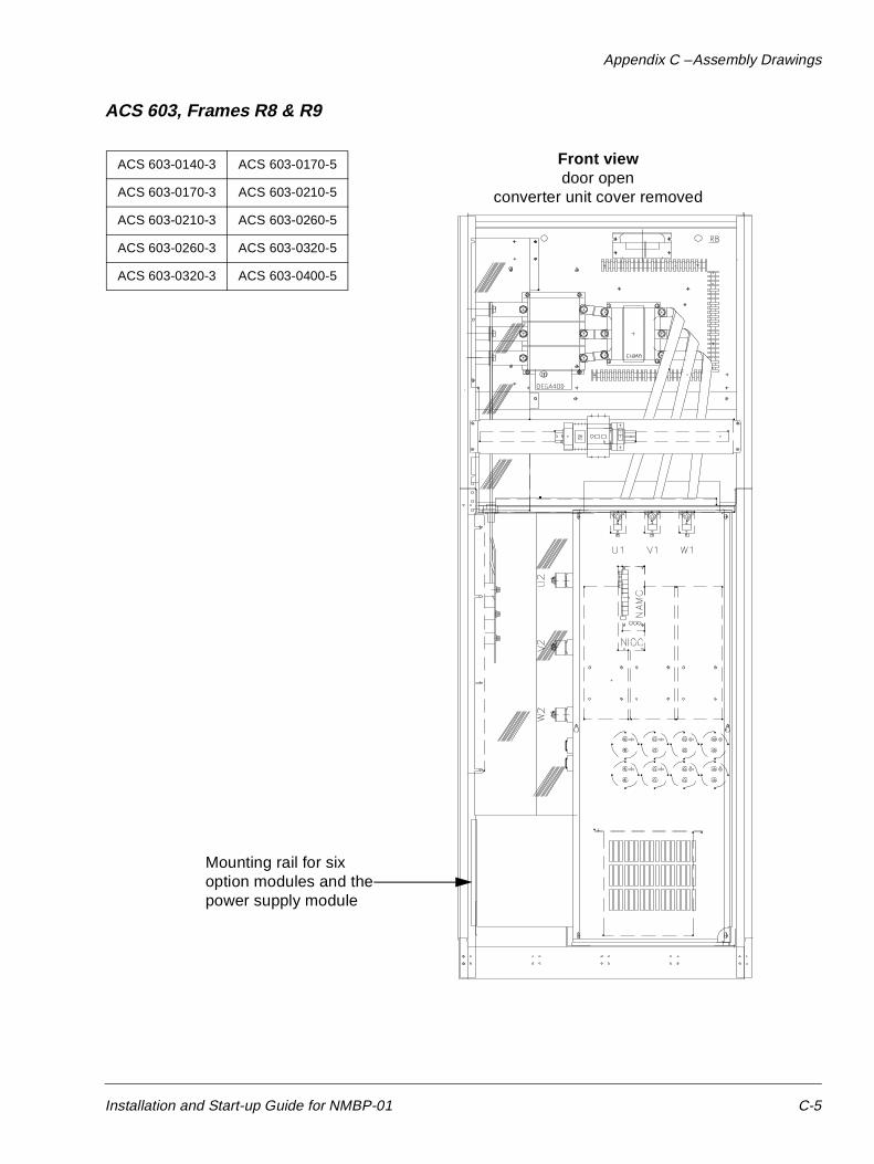
Appendix C – Assembly Drawings
ACS 603, Frames R8 & R9
ACS 603-0140-3 ACS 603-0170-5
ACS 603-0170-3 ACS 603-0210-5
ACS 603-0210-3 ACS 603-0260-5
ACS 603-0260-3 ACS 603-0320-5
ACS 603-0320-3 ACS 603-0400-5
Mounting rail for sixoption modules and thepower supply module
Front viewdoor open
converter unit cover removed
Installation and Start-up Guide for NMBP-01 C-5

Appendix C – Assembly Drawings
This page is intentionally left blank.
C-6 Installation and Start-up Guide for NMBP-01

ABB Industry OyVSD Products DivisionP.O.Box 211FIN-00381 HelsinkiFINLANDTelephone: +358-0-5641Telefax: +358-0-5642681
NM
BP
-01/
EN
3AF
Y 5
8919
802
R01
25 R
EV
BE
FF
EC
TIV
E: 1
996-
03-0
1S
UP
ER
SE
DE
S: N
one
