ace rnx channel emulator ace-rnx product introduction...10 • 5g channel model is cost option. this...
TRANSCRIPT
ACE RNX Channel Emulator
ACE-RNX
Product Introduction
2
A C E R N X S p e c i f i c a t i o n s
a n d F e a t u r e s
3
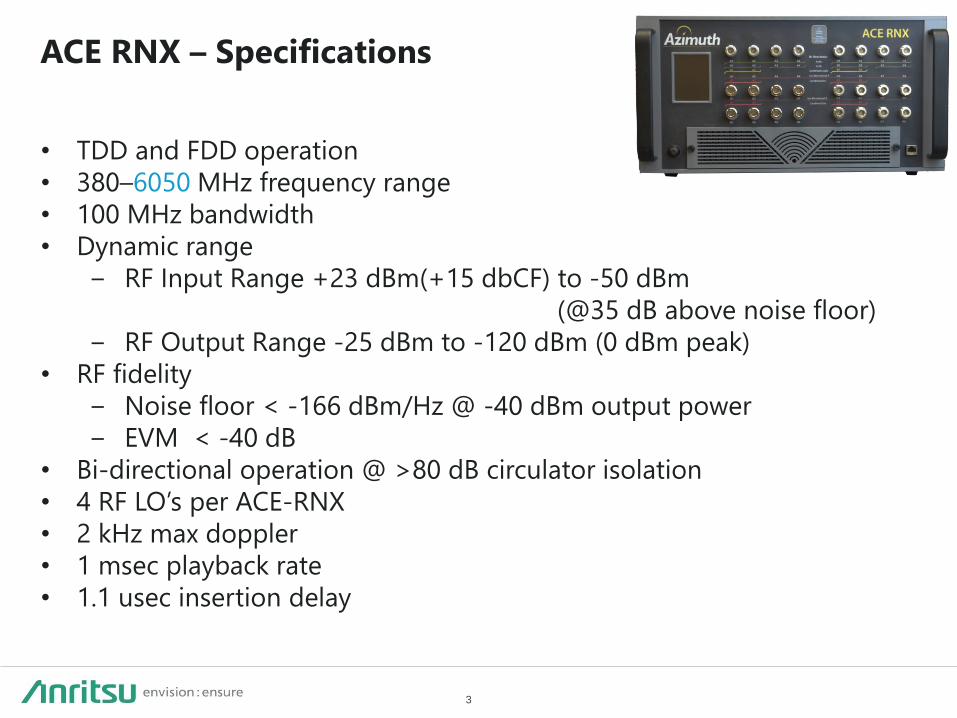
• TDD and FDD operation
• 380–6050 MHz frequency range
• 100 MHz bandwidth
• Dynamic range
− RF Input Range +23 dBm(+15 dbCF) to -50 dBm
(@35 dB above noise floor)
− RF Output Range -25 dBm to -120 dBm (0 dBm peak)
• RF fidelity
− Noise floor < -166 dBm/Hz @ -40 dBm output power
− EVM < -40 dB
• Bi-directional operation @ >80 dB circulator isolation
• 4 RF LO’s per ACE-RNX
• 2 kHz max doppler
• 1 msec playback rate
• 1.1 usec insertion delay
ACE RNX – Specifications
4
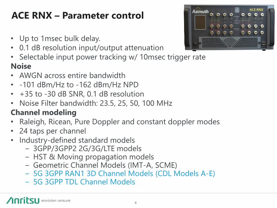
• Up to 1msec bulk delay.
• 0.1 dB resolution input/output attenuation
• Selectable input power tracking w/ 10msec trigger rate
Noise
• AWGN across entire bandwidth
• -101 dBm/Hz to -162 dBm/Hz NPD
• +35 to -30 dB SNR, 0.1 dB resolution
• Noise Filter bandwidth: 23.5, 25, 50, 100 MHz
Channel modeling
• Raleigh, Ricean, Pure Doppler and constant doppler modes
• 24 taps per channel
• Industry-defined standard models − 3GPP/3GPP2 2G/3G/LTE models − HST & Moving propagation models − Geometric Channel Models (IMT-A, SCME) − 5G 3GPP RAN1 3D Channel Models (CDL Models A-E) − 5G 3GPP TDL Channel Models
ACE RNX – Parameter control
5
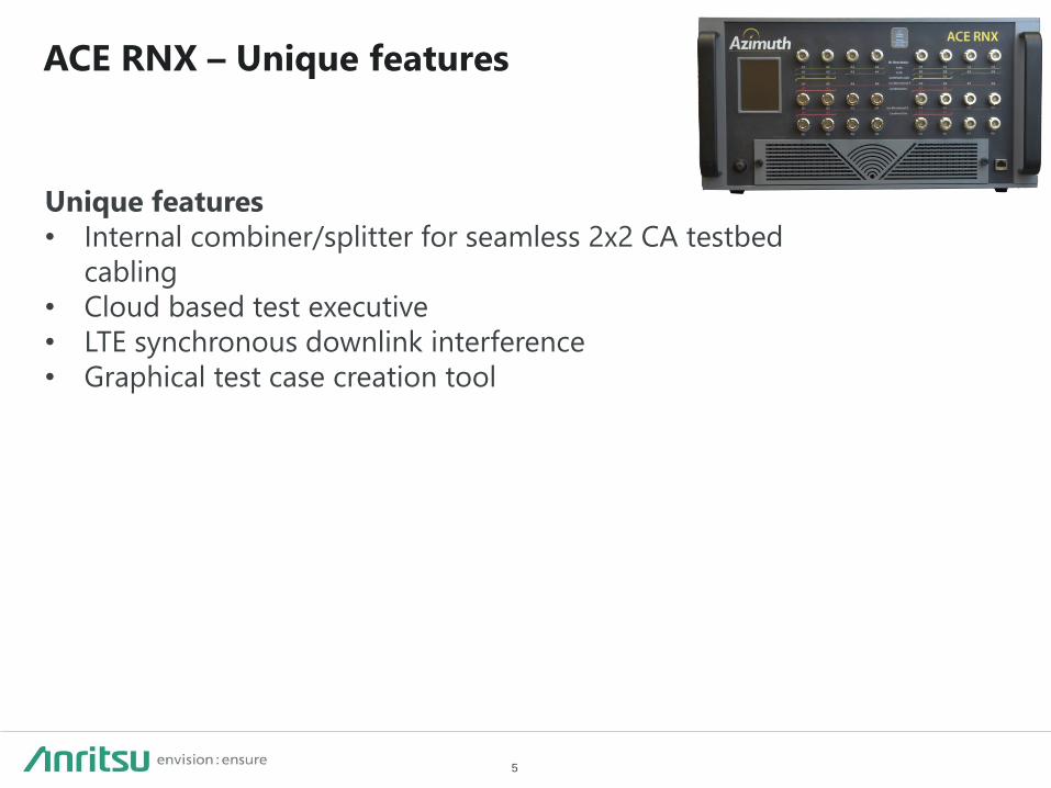
Unique features
• Internal combiner/splitter for seamless 2x2 CA testbed
cabling
• Cloud based test executive
• LTE synchronous downlink interference
• Graphical test case creation tool
ACE RNX – Unique features

6
• Dimension
− 0.45m (W) x 0.24m (H) x 0.73m (D) (MX)
− Can be mounted into lab rack
• Weight
− 36 kg
• Power Requirements
− Input: 100-240 VAC, 50-60 Hz, Max. 8.0 Amps at 120V,
4.0 Amps at 240V
− Mains supply voltage fluctuations are not to exceed 10
percent of the nominal supply voltage
ACE RNX – Box specifications
7
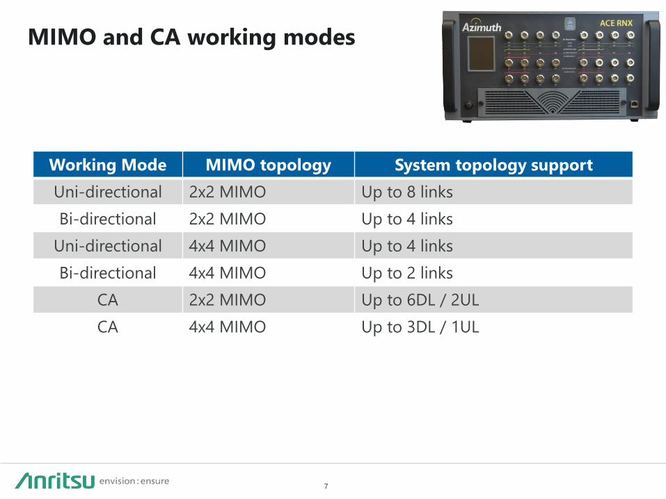
MIMO and CA working modes
Working Mode MIMO topology System topology support
Uni-directional 2x2 MIMO Up to 8 links
Bi-directional 2x2 MIMO Up to 4 links
Uni-directional 4x4 MIMO Up to 4 links
Bi-directional 4x4 MIMO Up to 2 links
CA 2x2 MIMO Up to 6DL / 2UL
CA 4x4 MIMO Up to 3DL / 1UL

8
A C E R N X 5 G C h a n n e l M o d e l

9
5G Technology Updates Release 15:
Release 15 for 3GPP Release 15 5G NR NSA standard is enhanced mobile broadband (eMBB) services.
Release 15 will include both the NSA and SA variants of 5G NR.
NSA and SA share common 5G NR physical layer specifications for the air interface
Main focus for the SA standardization is on the upper layers with full user and control plane capability and on
the next-gen core network architecture like network slicing, a more granular QoS model, and a more advanced
security architecture
Release 16
5G NR technologies spans from ultra-reliable low-latency communications (5G NR URLLC), to the utilization of
unlicensed and new spectrum sharing paradigms (5G NR-U and 5G NR-SS), to vehicle communications for
autonomous driving use cases (5G NR C-V2X), to the continued evolution of the 3GPP low power wide area
(LPWA) technologies (NBIOT/eMTC)
10
• 5G channel model is cost option. This model pack is a type of GSCM (Ray-based
Geometric Stochastic Channel Model) channel mode.
• GSCM is widely used for beamforming kind of testing, due to it has angle information,
which traditional TDL doesn’t have.
• Follows 3GPP 38.901 for RAN1
– Ray-based Geometric Stochastic Channel Model (GSCM)
– Five different sets of propagation conditions
– For now, we can generate to up 8x4 channels. For bigger topology it will be
updated in further release.
5G Channel Model - CDL
11
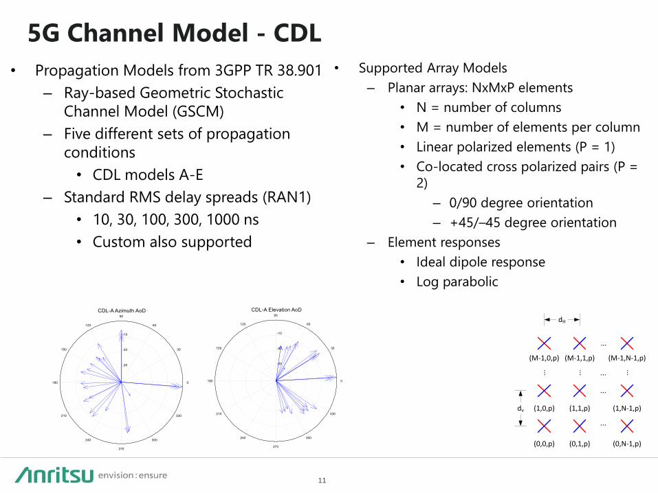
• Propagation Models from 3GPP TR 38.901
– Ray-based Geometric Stochastic
Channel Model (GSCM)
– Five different sets of propagation
conditions
• CDL models A-E
– Standard RMS delay spreads (RAN1)
• 10, 30, 100, 300, 1000 ns
• Custom also supported
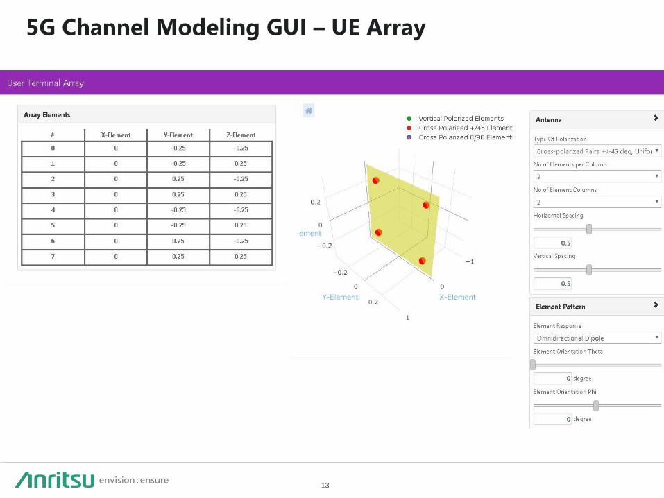
• Supported Array Models
– Planar arrays: NxMxP elements
• N = number of columns
• M = number of elements per column
• Linear polarized elements (P = 1)
• Co-located cross polarized pairs (P =
2)
– 0/90 degree orientation
– +45/–45 degree orientation
– Element responses
• Ideal dipole response
• Log parabolic
(0,0,p)
(1,0,p)
(M-1,0,p)
...
dv
(0,1,p)
(1,1,p)
(M-1,1,p)
...
...
(0,N-1,p)
(1,N-1,p)
(M-1,N-1,p)
...
...
...
...
dH
5G Channel Model - CDL

12
5G Channel Modeling GUI – gNodeB Array
13
5G Channel Modeling GUI – UE Array

14
5G Channel Modeling GUI – Geometric Modeling
Tool w/ Propagation Overview
Copyright© ANRITSU CORPORATION 15
M1TB-1ET18xxxx | CONFIDENTIAL |
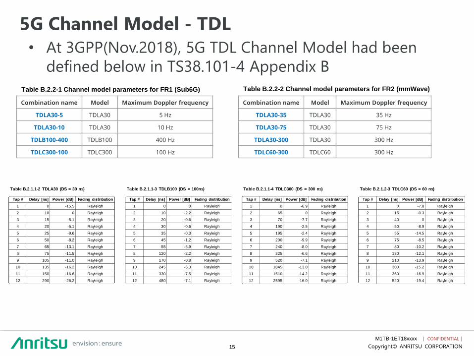
5G Channel Model - TDL
• At 3GPP(Nov.2018), 5G TDL Channel Model had been
defined below in TS38.101-4 Appendix B
Combination name Model Maximum Doppler frequency
TDLA30-5 TDLA30 5 Hz
TDLA30-10 TDLA30 10 Hz
TDLB100-400 TDLB100 400 Hz
TDLC300-100 TDLC300 100 Hz
Combination name Model Maximum Doppler frequency
TDLA30-35 TDLA30 35 Hz
TDLA30-75 TDLA30 75 Hz
TDLA30-300 TDLA30 300 Hz
TDLC60-300 TDLC60 300 Hz
Table B.2.2-2 Channel model parameters for FR2 (mmWave)
Table B.2.2-1 Channel model parameters for FR1 (Sub6G)
Table B.2.1.1-2 TDLA30 (DS = 30 ns)
Tap # Delay [ns] Power [dB] Fading distribution
1 0 -15.5 Rayleigh
2 10 0 Rayleigh
3 15 -5.1 Rayleigh
4 20 -5.1 Rayleigh
5 25 -9.6 Rayleigh
6 50 -8.2 Rayleigh
7 65 -13.1 Rayleigh
8 75 -11.5 Rayleigh
9 105 -11.0 Rayleigh
10 135 -16.2 Rayleigh
11 150 -16.6 Rayleigh
12 290 -26.2 Rayleigh
Table B.2.1.1-3 TDLB100 (DS = 100ns)
Tap # Delay [ns] Power [dB] Fading distribution
1 0 0 Rayleigh
2 10 -2.2 Rayleigh
3 20 -0.6 Rayleigh
4 30 -0.6 Rayleigh
5 35 -0.3 Rayleigh
6 45 -1.2 Rayleigh
7 55 -5.9 Rayleigh
8 120 -2.2 Rayleigh
9 170 -0.8 Rayleigh
10 245 -6.3 Rayleigh
11 330 -7.5 Rayleigh
12 480 -7.1 Rayleigh
Table B.2.1.1-4 TDLC300 (DS = 300 ns)
Tap # Delay [ns] Power [dB] Fading distribution
1 0 -6.9 Rayleigh
2 65 0 Rayleigh
3 70 -7.7 Rayleigh
4 190 -2.5 Rayleigh
5 195 -2.4 Rayleigh
6 200 -9.9 Rayleigh
7 240 -8.0 Rayleigh
8 325 -6.6 Rayleigh
9 520 -7.1 Rayleigh
10 1045 -13.0 Rayleigh
11 1510 -14.2 Rayleigh
12 2595 -16.0 Rayleigh
Table B.2.1.2-3 TDLC60 (DS = 60 ns)
Tap # Delay [ns] Power [dB] Fading distribution
1 0 -7.8 Rayleigh
2 15 -0.3 Rayleigh
3 40 0 Rayleigh
4 50 -8.9 Rayleigh
5 55 -14.5 Rayleigh
6 75 -8.5 Rayleigh
7 80 -10.2 Rayleigh
8 130 -12.1 Rayleigh
9 210 -13.9 Rayleigh
10 300 -15.2 Rayleigh
11 360 -16.9 Rayleigh
12 520 -19.4 Rayleigh

16
5G Sub6G End-to-End Test fading Configuration image
DL 2CC 4x4MIMO 100M/CC(200M/CA), UL 2CC 2x4MIMO 100M/CC(200M/CA),
RNX Bi-directional
All Conducted
Real BTS
(LTE Anchor)
DL: LTE fading
UL: 5G fading
2x2 Bi-directional
5G
DL: 5G Fading
Real BTS
(5G Sub6G)
UL: LTE fading
4x4 Bi-directional
Combiner

Copyright© Azimuth Systems, Inc. 17
RNX can be run with Real BTS, BTS tester, SG
ACE-RNX
Channel Emulator
Real BTS
RF Tester
Signaling Tester
SG
RF Fader can connect with various types of testers, BTS,
and make effective use of your existing facilities.
AP
Connect with various types of facilities
Copyright© Azimuth Systems, Inc. 18
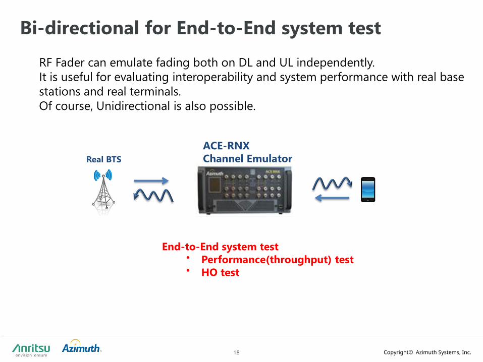
Bi-directional for End-to-End system test
Real BTS
RF Fader can emulate fading both on DL and UL independently.
It is useful for evaluating interoperability and system performance with real base
stations and real terminals.
Of course, Unidirectional is also possible.
ACE-RNX
Channel Emulator
End-to-End system test • Performance(throughput) test • HO test

Copyright© Azimuth Systems, Inc. 19
Multi Technology Fading Model & FTL support
ACE-RNX
Channel Emulator
LTE
EPA,ETU,EVA
(TS36.101/104)
ITU/SCME
W-CDMA
TS.34.121/122
TS25.101/102
GSM
TS05.05, TS45.005
High Speed Train
TS25.101/104,
TS36.101/104
WLAN 11n/ac
TgN (*3)
GMT 3D (*2)
5G 3D CDL-A/E (*2)
(TR38.901) Cdma2000
C.S0010/11/32/33
As a dedicated fading machine, RNX supports
• Various fading model of many communication standards,
• FTL offers to recreate the RF environment from the Field, in the Lab
• CIR offers faster support new channel models imported by offline-generated files
FTL(*2)
(Field to Lab)
CIR
(Channel Impulse
Response)
Butler
*1: Support from R5.0 (end of Mar. CY2019)
*2: Charged option
*3: Planed around H2 CY2019
5G TDLA/B/C
(TS38.101-4)(*1)

20
D i r e c t o r 3 Te s t E x e c u t i v e S W
21
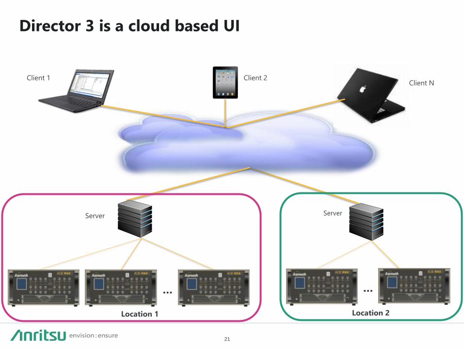
Director 3 is a cloud based UI
Server
Location 2
…
Client 1 Client 2 Client N
Server
Location 1
…
22
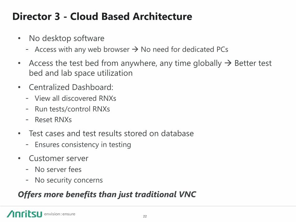
Director 3 - Cloud Based Architecture
• No desktop software
- Access with any web browser No need for dedicated PCs
• Access the test bed from anywhere, any time globally Better test
bed and lab space utilization
• Centralized Dashboard:
- View all discovered RNXs
- Run tests/control RNXs
- Reset RNXs
• Test cases and test results stored on database
- Ensures consistency in testing
• Customer server
- No server fees
- No security concerns
Offers more benefits than just traditional VNC
23
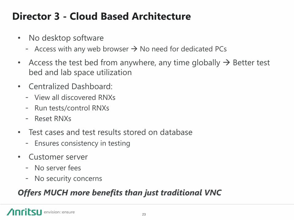
Director 3 - Cloud Based Architecture
• No desktop software
- Access with any web browser No need for dedicated PCs
• Access the test bed from anywhere, any time globally Better test
bed and lab space utilization
• Centralized Dashboard:
- View all discovered RNXs
- Run tests/control RNXs
- Reset RNXs
• Test cases and test results stored on database
- Ensures consistency in testing
• Customer server
- No server fees
- No security concerns
Offers MUCH more benefits than just traditional VNC
24
Director 3 Requirements
• Supported Operating System(64-bit, English)
– Windows 10 Pro
– Windows 10 Enterprise
– Windows 7 Professional
– Windows 7 Enterprise SP1
• NET framework 3.5(Windows10) or NET framework 3.5.1(Windows 7)
• NET framework 4.6.2
• Microsoft AppFabric 1.1
• Microsoft SQL Server Express 2014
• D3 is a webserver. User can access with any web browser. Eg,
http://127.0.0.1

25
Testbed Config
All the properties needed
to set up a connection
between the BS and MS in
one screen – Input power,
IPT, Crest factor, power
meters etc.
Graphical method of creating a
testbed and interacting with
corresponding properties
Click on link or a port to access
different types of properties

26
Link Builder
User can access
properties for multiple
links, single link
multiple ports or a
single link
User can add as
many core ACE
links or AzPlayer
links
User add as
many links as
their test
requires

27
Play Control
Play control
and status
Select previously created Testbed
and test case from link builder or
scenario builder
Mapped links to
the testbed
Click on arrows to
access DL or UL
properties
Access to other sections of
play control
Properties accessed
by clicking on ports,
links or multiple
links together

28
• CIR channel is a playback channel model, which can be generated by
our GSCM tool or customer’s Matlab or other programming tool.
• If customer want to import their own channel they need to check file
format. Refer to D3 user guide “Appendix A: Understanding the Format
of ASC Files”
Channel Impulse Response (CIR) Playback
Overview

29
Channel Impulse Response (CIR) Playback
• Support for importing ASC files
• Support for fading rates from almost zero to
2000 Hz
• Support for time-varying excess delays
– Glitch-free changes at physically
meaningful rates of delay change (<500
ns per sec, or 540 km/hr)
– Supported on half the number of RNX
delay taps
• Channel samples are generated offline (ie: Mat
Lab) and played back in the emulator
• Allows for faster support of new channel
models
– Customer-generated files can be imported
– Offline model generation requires no new
emulator firmware for new models
• Composed of
– Complex-valued channel amplitudes
– Excess delay values
– …for all excess delays, all MIMO paths, all
time samples
Geometric Modeling Tool
3D
GSCM Engine
Model Specification
CIR Database
File Format Translation /
Import
“Sampled H Matrix”
Director III
Player
...
EthernetFile Playback
User-Supplied CIR Files

30
V i r t u a l N e t w o r k E n v i r o n m e n t

31
LTE-A HetNet
• LTE‐A uses network densification/HetNet (a network of cells of
different sizes) to enhance system capacity
• One consequence of network densification is increased interference
• LTE-A offers many complex and advanced mechanisms (e.g., ICIC,
eICIC, FeICIC, NAICS, and advanced receivers) to handle this
interference
32
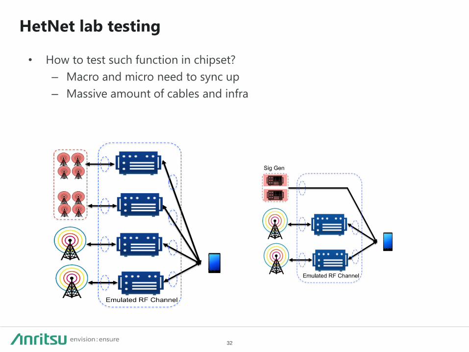
HetNet lab testing
• How to test such function in chipset?
– Macro and micro need to sync up
– Massive amount of cables and infra

33
VNE – Industry First Integrated Network Environment
Emulation
Industry’s first Integrated, Advanced Signal Generation Technology
• Embedded Complex Signal Generation Capability
LTE downlink (eNB) in the first release
• Generate and playback LTE downlinks
Emulate Macro cells, Small cells
Configure cell parameters
Add channel conditions
• Integrated LTE receivers for synchronization
Time or frame based synchronization
(Sync) needed to test xICIC, ABS
Eliminates the need for an external sync
Enables interoperability with live infrastructure and any base station
emulator
VNE creates the interfering cells

34
Create & Play Signals Dynamically
Design & Generate
Signal • Graphically create technology
specific signals
• Select LTE parameters Bandwidth, Transmission
Modes
FDD
Cyclic prefix, PHICH
CSRS
ABS pattern (standard, custom)
• Apply standard channel
models
• Create signal profiles
Playback
• Dynamically configure 1 or
more signals relative to real
test bed signals Integrated LTE receiver
monitors test bed
Set Timing, power, frequency
• Use as virtual macro/small
cell
• Dynamically update during
playback
35
VNE Specifications
• Interferer types
– FDD LTE downlink
– Synchronized and unsynchronized
• Can synchronize to up to 4 eNodeB’s
• Can synchronize to input signal of
+23 dBm to -50 dBm
– LTE macro cell and small cell
• Interferer numbers
– 12 independent interferers per ACE-
RNX
– 3 interferers per link
• Link level parameters
– -15 to +40 dB proportion (SIR)
– -1 to 1sec delay (100 nsec res)
– -100 to 100 kHz offset (10 Hz res)
• Interferer Controllable Parameters
– Bandwidth
– Cyclic prefix
– PHICH duration
– Number of eNB antennas
– Type of eNB array
– PCI (cell ID)
– PDSCH
• Transmission mode
• Traffic loading
• Rank proportion
• ABS pattern
• CFI value
– Propagation conditions
• Channel, doppler, correlation

36
S c e n a r i o B u i l d e r

37
Scenarios in the LTE-A World
• Lets take a LTE-A scenario, with 8 eNBs, each with CA and the device
moving through this environment
• Testing this scenario requires changing:
Power (or path loss)
Noise
Interference
Doppler
Power delay profile
Correlation
Propagation delay
• This has to be done 8 times (for each sector), for every device (across
links) at the desired resolution
• Creating these test scenarios manually is NOT a viable option
38
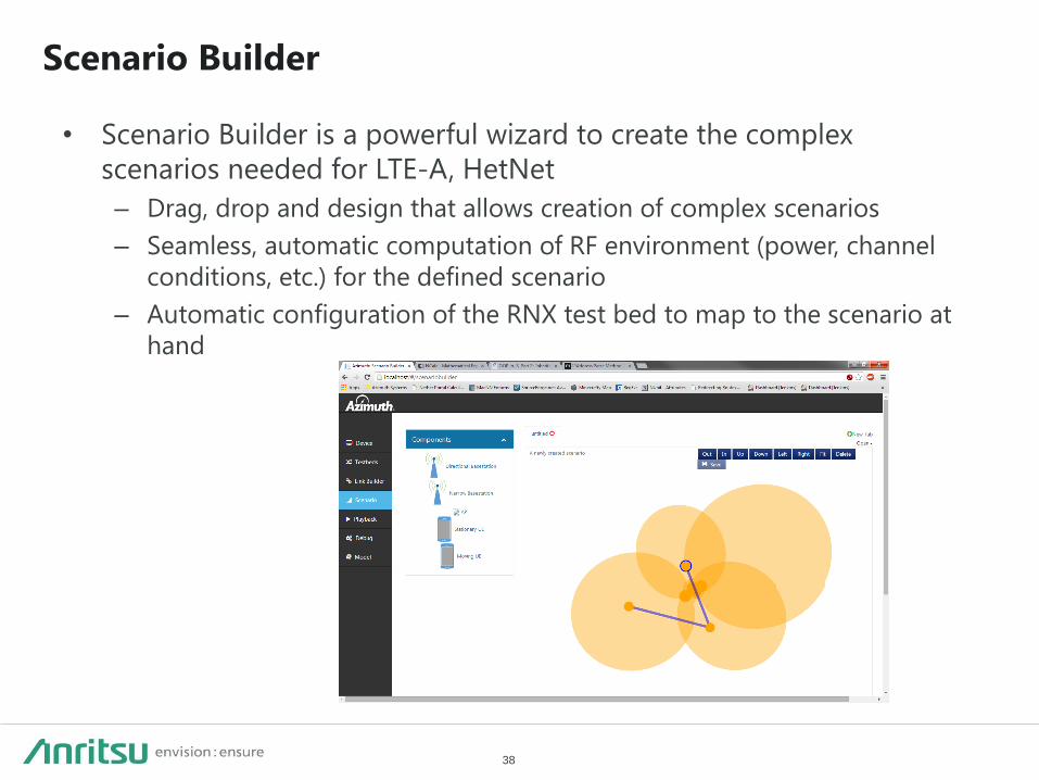
Scenario Builder
• Scenario Builder is a powerful wizard to create the complex
scenarios needed for LTE-A, HetNet
– Drag, drop and design that allows creation of complex scenarios
– Seamless, automatic computation of RF environment (power, channel
conditions, etc.) for the defined scenario
– Automatic configuration of the RNX test bed to map to the scenario at
hand

39
Scenario Builder Enables Creation of Complex Scenarios
Scenario Builder is a powerful wizard to create the complex
scenarios needed for LTE-A, HetNet
• Drag, drop and design that allows creation of complex scenarios
• Seamless, automatic computation of RF environment (power, channel conditions, etc.) for the defined scenario
• Automatic configuration of the RNX test bed to map to the scenario at hand
• Scenario builder library for commonly used scenarios: 3GPP carrier aggregation scenarios Operator deployment scenarios

40
Scenario Builder UI
Controls to
manage the canvas
Different types of
devices you can
drop on the canvas
A waypoint indicates a
point in the mobility
path. User can choose
channel conditions at
the beginning of
waypoint
User can drag this slider
to determine route of
mobility path
Properties associated
with an ENB or a
waypoint
Location and
coverage area of
the cell

41
Scenario Builder Example Use Cases
• Single-Cell Testing:
Near Cell, Far cell scenarios
Attenuation sweeps
Receive sensitivity tests
• Handover Testing:
Basic/Complex HO
Cell edge Ping-Pong
iRAT HO
• Carrier Aggregation Testing
Inter-Band CA
Intra-Band CA
• Small Cell Testing:
Small cell – Macro HO
Small cell Ping-Pong

42
F i e l d To L a b
( V i r t u a l D r i v e Te s t P l a y b a c k )
43
FTL Intro
• Field testing has some inherent challenges – Time consuming
– Expensive
– Results are not repeatable since the real world is dynamic
– R&D may not be local to where you see the issue
44
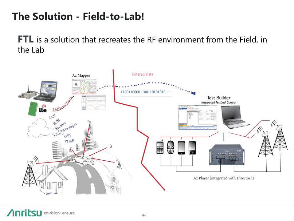
The Solution - Field-to-Lab!
FTL is a solution that recreates the RF environment from the Field, in
the Lab

45
How Does FTL Work?
Drive log
from RF
Scanner/
DM
Device in
the Lab AzMapper AzPlayer
ACE
Platform
FTL
Support for popular
platforms such as:
Qualcomm QXDM
JDSU W1314A
PCTEL SeeGull
Accuver XCAL
Anite Nemo
Huawei PROBE
• Intelligently post-processes
drive log data to remove
erroneous data
• Provides L1/L2/L3
visualization capabilities to
help narrow down problem
areas • Generates playback files
to be used with AzPlayer
• Streams RF channel
information to the ACE MX
• Recreates the complex RF
environment captured in the
drive log
• Creates a repeatable RF
environment.
• Device subject to
field conditions
• FTL also allows user
to subject device to
variants of the field
condition by modifying aspects
of the environment

46
AzMapper - Settings
47
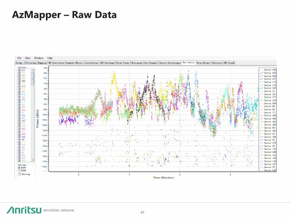
AzMapper – Raw Data
48
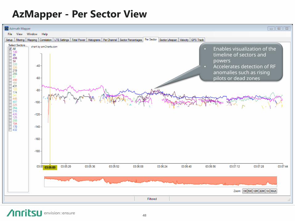
AzMapper - Per Sector View
• Enables visualization of the timeline of sectors and powers
• Accelerates detection of RF anomalies such as rising pilots or dead zones
49
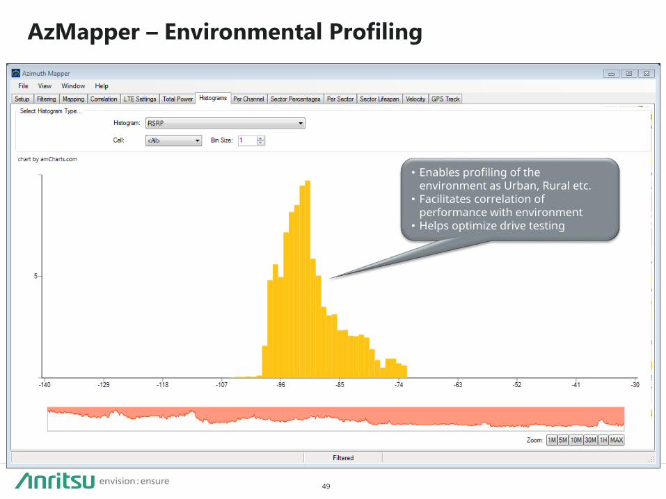
AzMapper – Environmental Profiling
• Enables profiling of the environment as Urban, Rural etc.
• Facilitates correlation of performance with environment
• Helps optimize drive testing

50
AzMapper - Contextual Display of Information
• Highlights locations of critical call events
(handovers etc.)
• Enables identification of problem spots
• Facilitates debugging of issues by
providing an integrated view of RF and
L2/L3

51
AzMapper in Action
• Accurately recreates the field RF environments via AzPlayer + ACE
• Accurate reconstruction of: - Power (RSSI, RSRP/RSCP - Noise (Ec/Io, SINR) - Velocity - Multi-path fading - Frequency shift - Antenna correlation - Propagation delay 4. Automate tests with Test
Builder
1. Capture field environment with a device or scanner
Field Data Log
2. Import field data into AzMapper
Support for popular platforms such as: Qualcomm QXDM JDSU W1314A PCTEL SeeGull R&S TSM-W Accuver XCAL Anite Nemo Ascom TEMS
3. Playback field data in the lab (AzPlayer + ACE)
AzPlayer + ACE
• Fully automate test cases - ACE MX - eNBs and BSEs - Handsets and USB data cards - QXDM, Metrico Datum, TEMS - FTP, iPerf, web browsing • Create test schedule or run 24/7
testing • Generates detailed reports - Throughput - Voice quality (PESQ) - Call Success/Failure - Call setup time - Handover duration - And more…
Test Builder
• Post-processes drive log data to remove erroneous data
• Provides visualization capabilities to help analysis of RF environment
• Intelligently maps real world sectors to fit lab test bed • Generates AzPlayer playback file

52
A C E R N X B e n e f i t s S u m m a r y
53
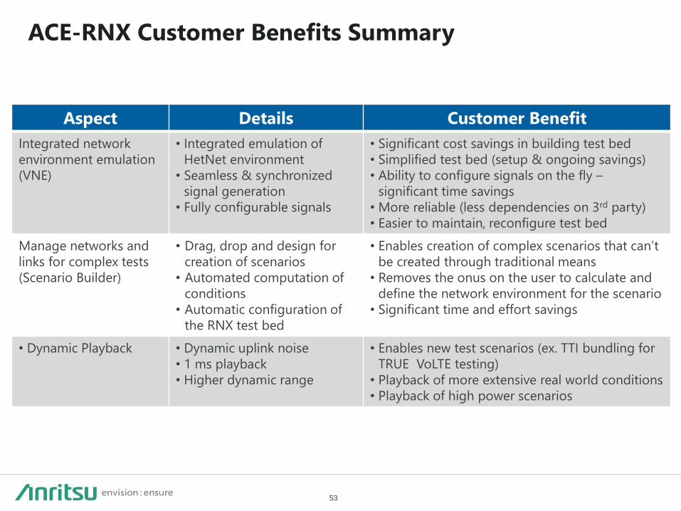
ACE-RNX Customer Benefits Summary
Aspect Details Customer Benefit
Integrated network
environment emulation
(VNE)
• Integrated emulation of
HetNet environment
• Seamless & synchronized
signal generation
• Fully configurable signals
• Significant cost savings in building test bed
• Simplified test bed (setup & ongoing savings)
• Ability to configure signals on the fly –
significant time savings
• More reliable (less dependencies on 3rd party)
• Easier to maintain, reconfigure test bed
Manage networks and
links for complex tests
(Scenario Builder)
• Drag, drop and design for
creation of scenarios
• Automated computation of
conditions
• Automatic configuration of
the RNX test bed
• Enables creation of complex scenarios that can’t
be created through traditional means
• Removes the onus on the user to calculate and
define the network environment for the scenario
• Significant time and effort savings
• Dynamic Playback • Dynamic uplink noise
• 1 ms playback
• Higher dynamic range
• Enables new test scenarios (ex. TTI bundling for
TRUE VoLTE testing)
• Playback of more extensive real world conditions
• Playback of high power scenarios
2019-6 MJM No. ACE-RNX-E-L-1-(3.00)