accuracy of six elastic impression materials used for complete-arch fixed partial dentures
TRANSCRIPT

Accuracy of six elastic impression materials used for
complete-arch fixed partial dentures
Jean-Pierre Stauffer, D.M.D .,* Jean-Marc Meyer, D.S.C.,** and Jean-Noel Nally, D.M.D., D.h.c.*** University of Geneva, School of Dentistry, Geneva, Switzerland
M odern elastic impression materials are highly accurate. With some elastic impression materials, excellent complete-arch fixed partial dentures can be made on a single cast poured from one master impression. Is this really possible? The problem of accuracy in a complete-arch impression is twofold: (1) local accuracy of each die and (2) generul accuracy (positional relation of the different dies with- in the complete-arch impression).
Previous research on hydrocolloids,‘. z polysulfide rubbers,Y-5 silicones,“, 7 and polyether rubber,” as well as comparative studies among these different groups,C’-‘3 indicate that only the local accuracy has been considered (single- or small-quadrant impressions).
This local accuracy is in the same range for the different groups.lOs I13 I4 The purpose of this research was to investigate the general accuracy in four groups of elastic impression materials represented by six different materials and tested with a complete-arch fixed prosthesis.
MATERIALS AND METHODS
The tested materials are presented in Table I. Two methods were used to evaluate the accuracy of the tested materials: ( 1)
visual comparison of the fit of a master fixed partial denture on different stone casts obtained from impressions made from a master model+ lo, I5 and (2) mea- surements of the stone casts.
Visual comparison
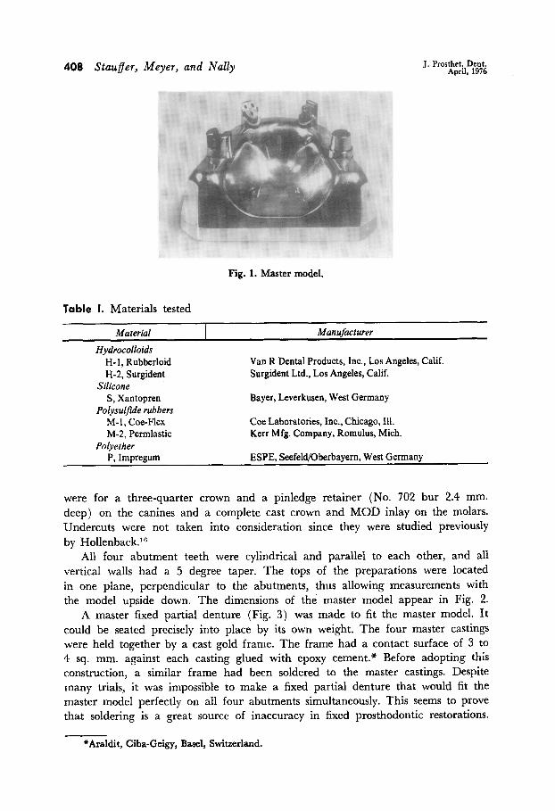
A master model (Fig. 1) was precisely machined with four prepared abutment teeth of stainless steel positioned in a maxilla of aluminum. The preparations
*Former postgraudate student at Indiana University; at present, in private practice in Geneva.
**Assistant Professor, Dental Materials.
*‘*Professor and Head, Division of Partial Prosthodontics.
408 Stauffer, Meyer, and Nally J. Prosthet. Dent. April, 1976
Fig. 1. Master model.
Table I. Materials tested
Material
Hydrocolloids H- 1, Rubberloid H-2, Surgident
Silicone S, Xantopren
Polysulfide rubbers M-l, Coe-Flex M-2, Permlastic
Polyether P, Impregum
Manufacturer
Van R Dental Products, Inc., Los Angeles, Calif. Surgident Ltd., Los Angeles, Calif.
Bayer, Leverkusen, West Germany
Coe Laboratories, Inc., Chicago, Ill. Kerr Mfg. Company, Romulus, Mich.
ESPE, Seefeld/Oberbayern, West Germany
were for a three-quarter crown and a pinledge retainer (No. 702 bur 2.4 mm. deep) on the canines and a complete cast crown and MOD inlay on the molars. Undercuts were not taken into consideration since they were studied previously by Hol1enback.l”
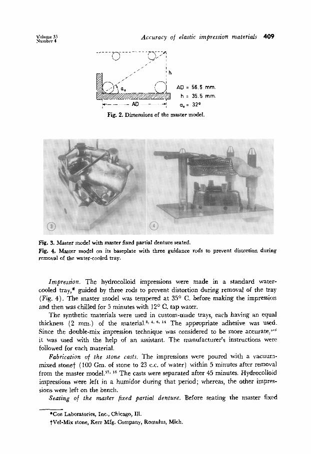
All four abutment teeth were cylindrical and parallel to each other, and all vertical walls had a 5 degree taper. The tops of the preparations were located in one plane, perpendicular to the abutments, thus allowing measurements with the model upside down. The dimensions of the master model appear in Fig. 2.
A master fixed partial denture (Fig. 3) was made to fit the master model. It could be seated precisely into place by its own weight. The four master castings were held together by a cast gold frame. The frame had a contact surface of 3 to 4 sq. mm. against each casting glued with epoxy cement.* Before adopting this construction, a similar frame had been soldered to the master castings. Despite many trials, it was impossible to make a fixed partial denture that would fit the master model perfectly on all four abutments simultaneously. This seems to prove that soldering is a great source of inaccuracy in fixed prosthodontic restorations.
*Araldit, Ciba-Geigy, Base& Switzerland.
Volume 35 Number 4
Accuracy of elastic impression materials 409
AD = 56.5 mm.
h = 35.5 mm.
- AD- a,: 32”
Fig. 2. Dimensions of the master model.
Fig. 3. Master model with master fixed partial denture seated. Fig. 4. Master model on its baseplate with three guidance rods to prevent distortion during removal of the water-cooled tray.
Impression. The hydrocolloid impressions were made in a standard water- cooled tray,* guided by three rods to prevent distortion during removal of the tray (Fig. 4). The master model was tempered at 35O C. before making the impression and then was chilled for 5 minutes with 12O C. tap water.
The synthetic materials were used in custom-made trays, each having an equal thickness (2 mm.) of the material. 3y 4* 6, I4 The appropriate adhesive was used. Since the double-mix impression technique was considered to be more accurate,“-” it was used with the help of an assistant. The manufacturer’s instructions were followed for each material.
Fabrication of the stone casts, The impressions were poured with a vacuum- mixed stone? (100 Gm. of stone to 23 C.C. of water) within 5 minutes after removal from the master model.17r l8 The casts were separated after 45 minutes. Hydrocollo:id impressions were left in a humidor during that period; whereas, the other irnpres- sions were left on the bench.
Seating of the master fixed partial denture. Before seating the master fixed
*Coe Laboratories, Inc., Chicago, Ill. tVel-Mix stone, Kerr Mfg. Company, Romulus, Mich.

410 Stauffer, Meyer, and Nally J. Prosthet. Dent. April, 1976
Fig. 5. Master fixed partial denture seated on a stone cast and horizontally positioned by means of a circular water level. Fig. 6. Measuring table with stone cast in place.
partial denture, the stone casts were carefully inspected with a magnifying glass. Little beads were removed, and the stone cast was then brushed with talcum pow- der to diminish friction.
The master fixed partial denture was placed on the cast. The cast was fixed on a surveyor base* so as to orient the master fixed partial denture in a horizontal position. This was checked by a circular water level placed on a small platform on top of the fixed partial denture (Fig. 5).
A 1 Kg. weight was then placed on the platform. To allow an even distribution, this cylindrical weight was slowly lowered at the end of a string.
Evaluation of the fit. The fit of the master fixed partial denture was evaluated with the help of a second person. The following marks according to the criteria listed were given: good adaptation-the master fixed partial denture fitted all four abutments; cervical interspaces between- castings and preparation were less than 0.2 mm. (The optimal clinical adaptation is of the order of 0.05 mm., which is the limit of the visual acuity.lg) ; unsatisfactory adaptation-one or two abut- ments did not fit well (i.e., an interspace of more than 0.2 mm.) ; bad adaptation- one or more abutments showed an interspace of 1 mm. or more.
Indirect measurements. The same casts were measured on a specially made measuring table (Fig. 6). They were placed upside down since the tops of all the teeth were in one horizontal plane. The rigid horizontal measuring table was pro- vided with an L-shaped stop in the lower left corner, which always allowed the stone cast to be placed in the same position.
Five dial gauges? were placed to measure the anteroposterior and lateral dis- placements of the abutment teeth. The contact rods were flat tipped (3 mm. in diameter) with rounded edges to prevent abrasion and chipping of the stone casts.
*The J. M. Ney Company, Hartford, Conn. tType 342, Compaq Geneva, Switzerland; one division = 0.002 mm.

Volumr 35 Numbcr 4 Accuracy of elastic impression materials 411
Frequency 10
6
0
H-Z H-l M-l M-2
Good adaptation
Unsatisfactory adaptation
Bad adaptation
Fig. 7. Frequency distribution of the stone casts as obtained by the visual comparisons of the fit.
Table II. Results for visual comparison of adaptation
Materials* P S M-l M-2 H-l H-2
Scores 25 23 22 21 17 13
*Materials underscored by the same line do not exhibit significant differences between them.
The posterior abutment placed in the L-shaped stop was considered as a fixed point. The dial gauges A and B measured the anteroposterior and lateral displace- ments of the anterior abutment on the left side. The C and D gauges measured the same displacement for the anterior abutment on the right side, and the E gauge measured the lateral displacement of the posterior abutment that was opposite the fixed point.
Measuring the casts
The measurements were compared to the master model and registered on stone casts that were at least 48 hours old; this was always done by the same operator in an air-conditioned room (24 + 2O C.). All measurements were repeated five times for each dial gauge, and the mean value was noted on the measuring sheet.
Ten casts were measured for each material, and the mean value and standard deviation for each dial gauge were calculated.
RESULTS
1.isual comparison. The frequency distribution of the three lev$s of fit for each of the six materials is given in Fig. 7. By giving points 3, 2, and 1 for good, un- satisfactory, and bad adaptation, respectively, a score was obtained for each ma- terial (Table II). A further ranking analysis based on the test by Kruskal and Wallis was used to define the significant differences among the materials.
Indirect measurements. The means of ten values, corresponding to the ten casts obtained on each of the five dial gauges, were calculated with the corresponding standard deviations for the six tested materials.
To better visualize the complex data related to the deformation of the stone casts, the following four steps were taken.

412 Stauffer, Meyer, and Nally J. Prosthet. Dent. April, 1976
A H-2 H-l
? f 8’
: I’ ----- Hydrocolloids
: ,’ I’ -.-.- Polysulfide rubbers
! j . . . . . . . . . . . . polyether --- Silicone
Fig. 8. Vectorial representation of the displacements of the abutment teeth.
Fig. 9. Mean vector sums for the six tested materials.
(1) The orthogonal displacement of the three abutment teeth (the fourth one being a fixed point) was used to define three vectors (Fig. 8). The vectors corre- sponding to the two anterior teeth were obtained from the A and E and the C and D dial gauges, respectively, whereas, the vector of the third abutment was given by the E dial gauge since the displacement was allowed along the x axis only. The length of the vector represented the amount of the deformation of each abutment tooth, and the angle of the vector gave the direction of this deformation.
(2) By translation, the three vectors were given a common origin. (3) By adding the three vectors of one cast, a single vector was obtained
called “vector sum” with a certain length and a certain direction as compared to the 32 degree reference angle of the master model (Fig. 2).
(4) By taking the mean of the vector sums for the ten casts of a given ma- terial, the mean vector sum for each of the six materials was obtained (Fig. 9).
The amount (length of vectors) and the direction of the deformation (as com- pared to an isotropic deformation of 32 degrees) of the different materials were observed. The amount of deformation observed in the vector sums cannot be re- lated with the discrepancies observed in the visual test on every single abutment tooth.
In order to compare the different materials, two values were considered: the amount of the deformation and its reproducibility.
Deformation. The size and type (isotropic or not) of deformation were defined as that surface determined by the mean vector sum of a given material when ro- tating around the origin, from the reference direction (32 degrees) to its own di- rection (Fig. 9). This surface, called “surface of deformation,” was calculated for the six materials, and the results are given in Fig. 10.
Reproducibility. The dispersion of the measurements obtained from the dial

Volume 35 Number 4
To (flrn2)
8000
Accuracy of elastic impression materials 413
Z& (pm21
7462 1
6000
3000
1000
0
@
-6152
H-2 H-l M-l M-2 P s
Antero- Nearly
posterior isotropic
Lateral
2000
1800
- 1600
woo
1200
loo0
- 000
600
LOO
200
cl L
0
1906 r
1609 1
H-2 H-l M-l M-2 P s
Fig. 10. Mean deformations. Positive values refer to lateral distortions and negative ones to anteroposterior distortions.
Fig. 11. Values obtained for the reproducibility. The smaller the values, the better the repro- ducibility.
gauges affected both the length and the direction of the vectors which were used to describe them. In order to relate these variations, a surface was defined by the confidence limits from the standard deviations of the lengths and angles of the considered vectors. The smaller the surface, the better the reproducibility. The values obtained for the six materials are shown in Fig. 11.
DISCUSSION
The two methods chosen to quantitatively describe the accuracy of stone casts obtained from the six tested materials give three different types of information. The visual comparison closely relates to the over-all adaptation of the master fixed partial denture; whereas, the indirect measurements give exact values of the dis- placements of the abutment teeth. These allow an accurate comparison among the different materials as well as the evaluation of their reproducibility.
The values of the surfaces of deformation (Fig. 10) relate not only to the size of these areas but also to the nature of the deformation involved. When looking again at Fig. 9, it appears that while the polysulfide rubbers have a relatively small isotropic deformation, the two hydrocolloids, the polyether rubber, and the silicone have a more important deformation but of a very different character (lateral for P and S vs. anteroposterior for H-l and H-2).

414 Staufer, Meyer, and Nally J. Prosthet. Dent. April, 1976
With the particular complete-arch fixed prosthesis considered in this study, the best fit by visual evaluation seems to take place with casts that have a lateral deformation (P and S) ; whereas, the materials that produce casts having an iso- tropic (M-l and M-2) and an anteroposterior (H-Z and H-2) deformation give less satisfactory results. However, generalizations to other types of fixed prostheses are not necessarily valid.
As far as the reproducibility is concerned, no comparison is attempted between the calculated surface of reproducibility and the two other factors since the varia- tion in the results does not relate to the quality of these results. Material H-I, for example, has a good reproducibility but shows a large surface of deformation and has one of the poorest fits by visual evaluation.
The poor performance of the hydrocolloids in this study, as compared with their excellent performance when tested for single restorations, can be explained by the uneven thickness of the material in the stock tray. This source of inaccuracy is more critical in a long-span, complete impression.
CONCLUSIONS
1. The accuracy of four types of impression materials used to make a complete- arch fixed partial denture was evaluated by visual comparison and indirect mea- surement methods.
2. None of the tested materials allows safe finishing of a complete-arch fixed partial denture on a cast poured from one single master impression.
3. All of the tested materials can be used for impressions for a complete-arch fixed partial denture provided it is not finished on one single cast. Errors can be avoided by making a new impression with the fitted castings in place. Assembly and soldering should be done on the second cast.
4. In making the master fixed partial denture for this study, inaccurate solder- ing was a problem that was overcome with the use of epoxy glue. Hence, soldering seems to be a major source of inaccuracy for every fixed partial denture.
References
1. Phillips, R. W., and Ito, F. G.: Factors Influencing the Accuracy of Reversible Hydro- colloid Impressions, J. Am. Dent. Assoc. 43: 1-17, 1951.
2. Skinner, E. W., and Hoblit, N. E.: Study of the Accuracy of Hydrocolloid Impressions, J. PROSTHET. DENT. 6: 80-86, 1956.
3. Fairhurst, C. W., Furman, T. Cl., Schallhorn, R. V., Kirkpatrick, E. L., and Ryge, G.: Elastic Properties of Rubber Base Impression Materials, J. PROSTHET. DENT. 6: 534-542, 1956.
4. Schnell, R. J., and Phillips, R. W.: Dimensional Stability of Rubber Base Impressions and Certain Other Factors Affecting Accuracy, J. Am. Dent. Assoc. 57: 39-48, 1958.
5. Skinner, E. W., and Cooper, E. N.: Desirable Properties and Use of Rubber Impression Materials, J. Am. Dent. Assoc. 51: 523-536, 1955.
6. Gihnore, W. H., Schnell, R. J., and Phillips, R. W.: Factors Influencing the Accuracy of Silicone Impression Materials, J. PROSTHET. DENT. 9: 304-314, 1959.
7. Berger, R.: Physikalische Eigenschaften von Abdruckmaterialien auf Silicon-Kautschuk- Basis, Thesis, 1959, Zahnartzliches Institut der Universitit Ziirich.
8. Schwindling, R.: Massnahmen zur Vermeidung der Abbindekontraktion des Abformwerk- stoffes Impregum, Dtsch. Zahnaerztl. Z. 25: 899-902, 1970.

Volume 35 Number4 Accuracy of elastic impression materials 415
9. Pfannenstiel, H.: Vergleichende Untersuchungen von Abdruckform-Materialien aus der Sicht des Dental-Labors, Dent. Labor 18: 19-23, 1970.
10. Bassett, R. W., Van der Heide, J. D., and Smith, D. D.: Clinically Oriented Tests Com- paring Accuracy of Elastic Impression Materials, J. South. Calif. Dent. Assoc. 37: 47-57, 1969.
11. Hollenback, G. M.: Study of the Physical Properties of Elastic Impression Materials. Part III, J. South. Calif. Dent. Assoc. 31: 369.372, 1963.
12. Chong, M. P., and Docking, A. R.: Some Setting Characteristics of Elastomeric Impressj.on Materials. Part II, Aust. Dent. J. 14: 295-301, 1969.
13. Sawyer, H. F., Birtles, J. T., Neimann, R., and Podshadley, A. G.: Accuracy of Casts Produced From Seven Rubber Impression Materials, J. Am. Dent. Assoc. 87: 126-1130, 1973.
14. Phillips, R. W.: Physical Properties and Manipulation of Rubber Impression Materials, J. Am. Dent. Assoc. 59: 454-458, 1959.
15. Schnell, R. J., and Phillips, R. W.: Dies for Measuring Accuracy of Impressions, Dent. Progr. 2: 249-255, 1962.
16. Hollenback, G. M.: Study of the Physical Properties of Elastic Impression Materials. Part II, J. South. Calif. Dent. Assoc. 31: 227-230, 1963.
17. Toreskog, S., Phillips, R. W., and Schnell, R. J.: Properties of Die Materials: A Compara- tive Study, J. PROSTHET. DENT. 16: 119-131, 1966.
18. Astiz, P. H., and Lorencki, S. F.: Comparative Accuracy of Commonly Used Dental Die Materials, J. Can. Dent. Assoc. 35: 320-323, 1969.
19. Nelsen, R. J., Wolcott, R. B., and Paffenbarger, G. C.: Fluid Exchange at the Margins of Dental Restorations, J. Am. Dent. Assoc. 44: 288-295, 1952.
DR. STAUFFER AVENUE DE CHAMPEL, 6 1206 GENEVA, SWITZERLAND
DRS. MEYER AND NALLY ECOLE DE M~DECINE DENTAIRE 19, RUE BARTHELEMY-MENN 12 11 GENEVA 4, SWITZERLAND