accuharvest on-combine - zeltex · web viewand operate the zeltex accuharvest on-combine grain...
TRANSCRIPT
AccuHarvest On-CombineGrain Analyzer
User’s ManualVersion 1.5
This manual provides you the information needed to install and operate the Zeltex AccuHarvest On-Combine
Grain Analyzer and the software provided.
ZELTEX, INC.130 Western Maryland ParkwayHagerstown, Maryland 21740 USA
Phone: 301-791-7080Fax: 301-733-9398E-mail: [email protected]
© Zeltex, Inc. 2007
TABLE OF CONTENTS
TABLE OF CONTENTS..................................................................................................2
DEFINITIONS...................................................................................................................3
WARNING.........................................................................................................................4
PARTS AND DESCRIPTIONS........................................................................................5
INSTALLING THE ACCUHARVEST...........................................................................8
MOUNTING...................................................................................................................8
REMOVING THE SENSE HEAD................................................................................11
CHANGING THE INTERNAL WINDOW..................................................................12
USING THE DATALOGGER.......................................................................................13
GENERAL.....................................................................................................................13
ADJUSTING BRIGHTNESS........................................................................................13
COLLECTING DATA..................................................................................................13
OTHER DATALOGGER FUNCTIONS......................................................................14
USING THE OPTIONAL MAPPING SOFTWARE........................................................15
2

DEFINITIONS
Bias – The average overall shift of the calculated results from the ideal laboratory values. A Bias Adjustment will compensate for this.
Bin Average – When started, the Bin Average will keep averaging all readings until stopped.
Calibrate Motors – This function determines the optimal settings for the motors to ensure the most accurate results. Grain must be flowing through the AccuHarvest during this process.
CGE – Clean Grain Elevator.
Constituent – Organic compounds that are found in the sample being tested, such as Protein, Moisture, etc.
Data Card – The small card with the DataLogger where the collected data is stored.
DataLogger – The device used to collect data from the AccuHarvest and GPA and merge it into one easy to manage file.
Layer – The mapping software uses layers to describe different aspects of the field. There may be a Protein layer, a Yield layer, a crop layer, etc.
Slope and Bias – More than just a simple shift in calibration. A Slope and Bias adjustment will compensate for this.
3
WARNING
Proper use and care of the AccuHarvest On-Combine Grain Analyzer is critical. Mounting, wiring, or any other use of this instrument that does not follow the
instruction of this manual could cause calibration loss and/or damage to the AccuHarvest.
The AccuHarvest On-Combine Grain Analyzer contains moving parts. Please take precautions and
keep fingers clear of these parts while the AccuHarvest is in use.
The AccuHarvest On-Combine Analyzer is not Explosion Proof: Reasonable care must be used in
handling of this instrument.
4

5
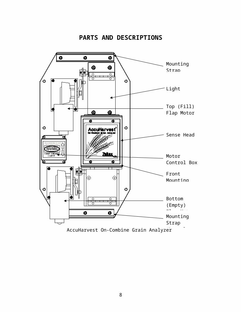
PARTS AND DESCRIPTIONS
AccuHarvest On-Combine Grain Analyzer
6
Light Shield
Sense Head
Front Mounting Clamp
Top (Fill) Flap Motor
Bottom (Empty) Flap Motor
Motor Control Box
Mounting Strap Channel
Mounting Strap Channel

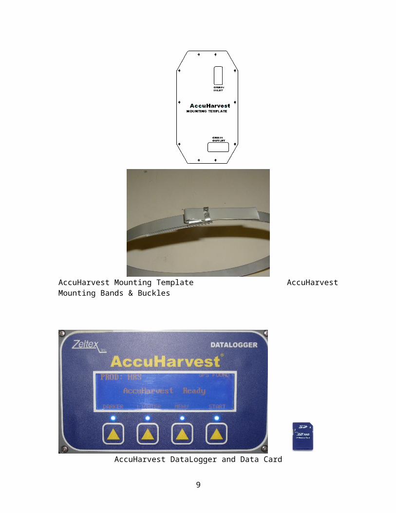
AccuHarvest Mounting Template AccuHarvest Mounting Bands & Buckles
AccuHarvest DataLogger and Data Card
7
Data Card Reader GPS with Mounting Bracket
Optional Mapping Software Package
8
INSTALLING THE ACCUHARVEST
MOUNTINGThe AccuHarvest must be mounted onto the upside of the clean grain elevator on your combine. This will allow the AccuHarvest to accurately analyze the grain as soon as it is harvested. When the AccuHarvest has finished analyzing a sample, the sample will then be released into the downside of the clean grain elevator.
1) Locating the AccuHarvest on the Clean Grain Elevator
Use the enclosed Mylar mounting template to find the best location for mounting the AccuHarvest on the CGE. The template shows locations for the grain inlet and outlet holes, as well as ten locations for mounting bolts. Be sure the template is oriented correctly (so that writing is legible).
The AccuHarvest must be mounted vertically +/- 5 degrees. The grain inlet hole must be located so that the instrument can receive grain from the up-bound elevator paddles, and the grain outlet hole must allow grain to enter the elevator on the return side. Cut the inlet and outlet holes in the CGE.
When mounting the AccuHarvest, temporarily removing the Sense Head and the two motor assemblies will reduce weight and may make handling less awkward. Take care not to dislodge or misalign the two gaskets around the grain inlet and outlet holes.
2) Securing the AccuHarvest
There are two ways to secure the AccuHarvest in place -- bolts and straps. Around the outer edge of the plate, there is a series of holes for 1/4" (6mm) mounting bolts. Any of these can be used. It is recommended that if the AccuHarvest is secured only with bolts, at least 4 bolts be used, well separated to ensure the plate stays firmly against the CGE. Note that if required, mounting holes may be drilled in other locations, as long as they do not interfere with the AccuHarvest components or mechanisms.
The other method of securing the AccuHarvest is to use steel mounting straps. In theAccuHarvest accessories are two 4’ (1.2 M) steel straps, and strap buckles. These can hold the AccuHarvest to the CGE, riding in the two strap channels at the top and bottom of the plate. Note that if the straps are used, it is still recommended that at least two 1/4" (6mm) bolts be used (well separated) to provide positive alignment of the AccuHarvest in relation to the grain inlet and outlet holes in the CGE.
9

10
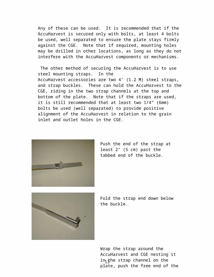
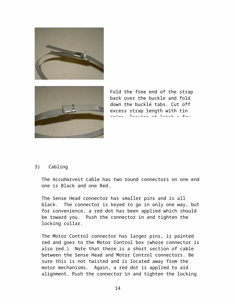
Push the end of the strap at least 2" (5 cm) past the tabbed end of the buckle.
Fold the strap end down below the buckle.
Wrap the strap around the AccuHarvest and CGE nesting it in the strap channel on the plate, push the free end of the strap through the buckle and pull as tight as possible.
Fold the free end of the strap back over the buckle and fold down the buckle tabs. Cut off excess strap length with tin snips, leaving at least a few inches in case adjustments are necessary.

3) Cabling
The AccuHarvest cable has two round connectors on one end one is Black and one Red.
The Sense Head connector has smaller pins and is all black. The connector is keyed to go in only one way, but for convenience, a red dot has been applied which should be toward you. Push the connector in and tighten the locking collar.
The Motor Control connector has larger pins, is painted red and goes to the Motor Control box (whose connector is also red.) Note that there is a short section of cable between the Sense Head and Motor Control connectors. Be sure this is not twisted and is located away from the motor mechanisms. Again, a red dot is applied to aid alignment. Push the connector in and tighten the locking collar.
Dangling from the Motor Control connector are two 2-wire motor connectors labeled "1" and "2". Connect "1" to the upper motor, and "2" to the lower motor. Insert the connectors fully and take care that the wires are dressed away from the mechanisms.
There are now three cables dangling from the AccuHarvest. Two of these are two-wire power cables, and one is an RS232 cable with a 9 pin connector on the end.
The two power cables are routed to the combine power panel. Red is +12 and Black is Ground. (There are two cables for purposes of noise reduction.) Preferably they are dressed away from other power cables and if possible, slightly away from each other. Secure them with plastic ties as appropriate. There are 5 amp automotive fuses and spares inside the front covers of both the Sense Head and the Motor Control box.
The RS232 cable is routed to the combine cab to connect to the AccuHarvest DataLogger. If possible, dress it away from other cabling -- especially power cables. Secure as appropriate with plastic ties.
11
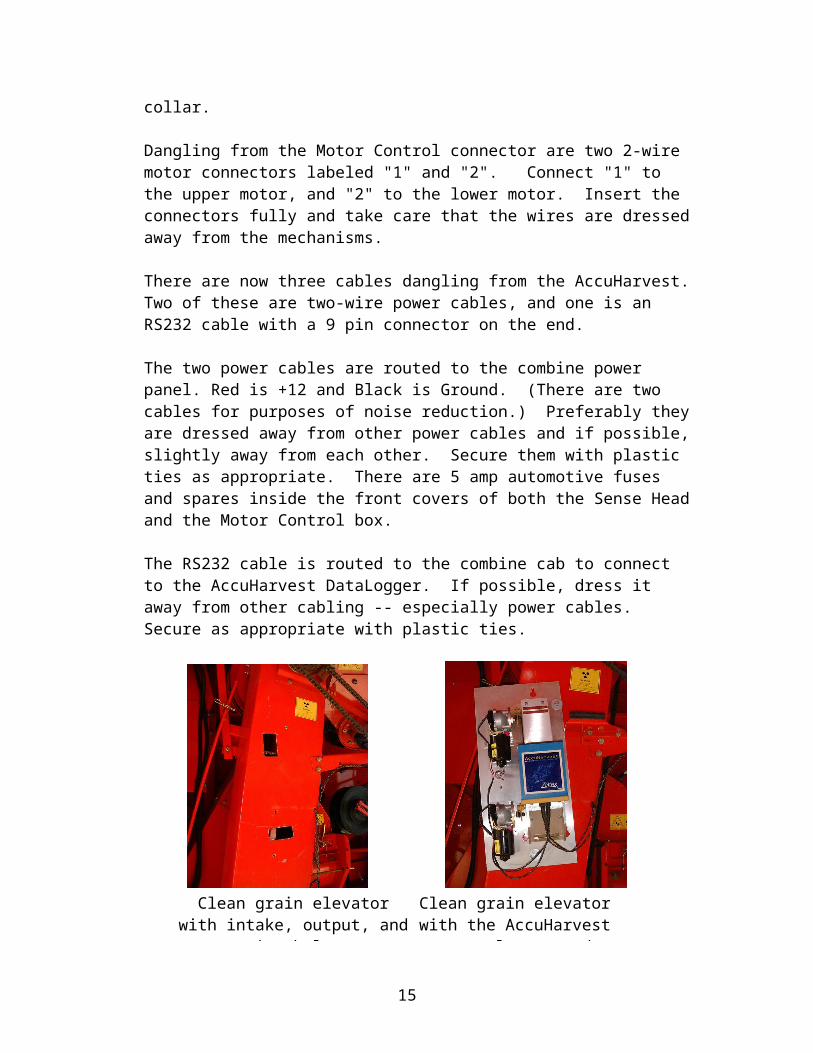
Clean grain elevator with intake, output, and mounting holes cut
Clean grain elevator with the AccuHarvest properly mounted
4) Mount the GPS Antenna to the highest point available on the combine. Feed the power/RS232 cable into the combine cab to connect to the AccuHarvest DataLogger.
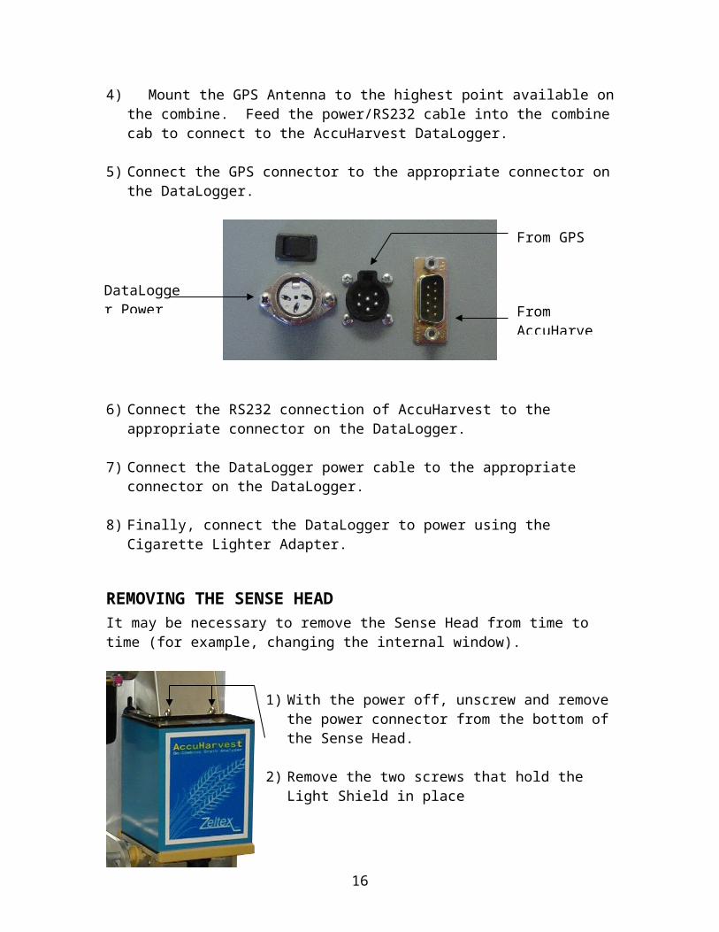
5) Connect the GPS connector to the appropriate connector on the DataLogger.
6) Connect the RS232 connection of AccuHarvest to the appropriate connector on the
DataLogger.
7) Connect the DataLogger power cable to the appropriate connector on the DataLogger.
8) Finally, connect the DataLogger to power using the Cigarette Lighter Adapter.
REMOVING THE SENSE HEADIt may be necessary to remove the Sense Head from time to time (for example, changing the internal window).
1) With the power off, unscrew and remove the power connector from the bottom of the Sense Head.
2) Remove the two screws that hold the Light Shield in place
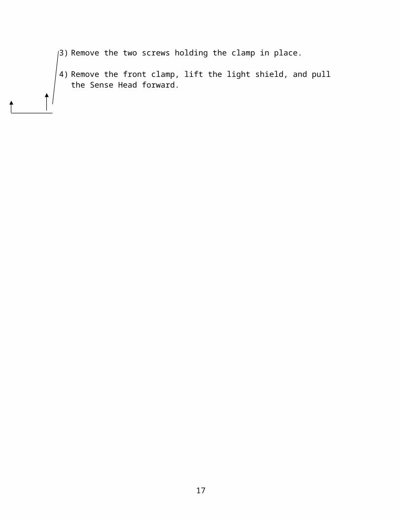
3) Remove the two screws holding the clamp in place.
4) Remove the front clamp, lift the light shield, and pull the Sense Head forward.
12
DataLogger Power
From GPS
From AccuHarvest
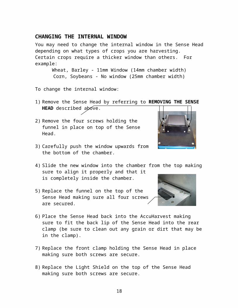
CHANGING THE INTERNAL WINDOWYou may need to change the internal window in the Sense Head depending on what types of crops you are harvesting. Certain crops require a thicker window than others. For example:
Wheat, Barley - 11mm Window (14mm chamber width)Corn, Soybeans - No window (25mm chamber width)
To change the internal window:
1) Remove the Sense Head by referring to REMOVING THE SENSE HEAD described above.
2) Remove the four screws holding the funnel in place on top of the Sense Head.
3) Carefully push the window upwards from the bottom of the chamber.
4) Slide the new window into the chamber from the top making sure to align it properly and that it is completely inside the chamber.
5) Replace the funnel on the top of the Sense Head making sure all four screws are secured.
6) Place the Sense Head back into the AccuHarvest making sure to fit the back lip of the Sense Head into the rear clamp (be sure to clean out any grain or dirt that may be in the clamp).
7) Replace the front clamp holding the Sense Head in place making sure both screws are secure.
8) Replace the Light Shield on the top of the Sense Head making sure both screws are secure.
9) Screw the power cable back onto the bottom of the Sense Head by lining up the notches. Make sure you feel the connector collar “click” into place.
13
USING THE DATALOGGER
GENERALOnce the DataLogger has been set up, turn it on using the on/off switch on the side of the DataLogger. The AccuHarvest must be powered on for the DataLogger to work. The DataLogger will reset the AccuHarvest and initialize communication. If the DataLogger fails to locate the AccuHarvest, check all of the cabling and cycle power on the DataLogger.
The DataLogger must also have the Data Card inserted before it will function properly. All data collected by the DataLogger will be stored on this Data Card.
The DataLogger has four buttons are used to select options, navigate through menus, or enter values. The bottom line of the display will show you which options are available for each button.
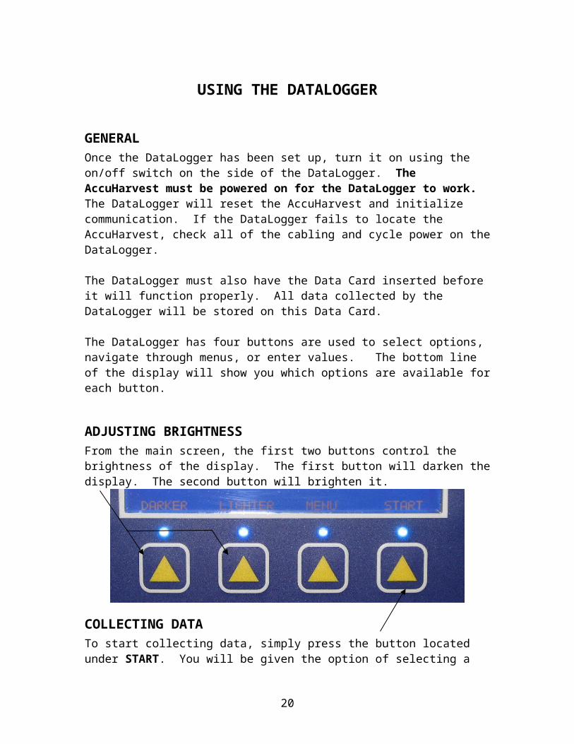
ADJUSTING BRIGHTNESSFrom the main screen, the first two buttons control the brightness of the display. The first button will darken the display. The second button will brighten it.
COLLECTING DATATo start collecting data, simply press the button located under START. You will be given the option of selecting a previously saved field name or entering your own field name (must be 8 characters or less in length).
Once the field name has been entered, you will be prompted to “Calibrate Motors?” The AccuHarvest discharges small deposits of the product during the reading. Calibrating the motors ensures that the AccuHarvest does not dump too much or too little out during the reading. The AccuHarvest cannot calibrate the motors if it is not being fed grain. This calibration only needs to be done once per product. This should also be done when field conditions change or if you need to restore the backup settings to the AccuHarvest. Once the motor calibration is complete, the AccuHarvest will start collecting and displaying your data.
14
While collecting data the four buttons provide you with data collecting options:
STATUS – The STATUS button will provide you information such as the product being collected, the status of the GPS, and the number of readings taken.
REAL/BIN – This will toggle between “Real Time” results and “Bin Average” results.
BIN START – This will start Bin Averaging (defined in DEFINITIONS). To stop Bin Averaging, press this button again.
STOP – This will stop the Data Collecting process.
OTHER DATALOGGER FUNCTIONSThe DataLogger also provides you with the ability to change some settings or make adjustments to the AccuHarvest. To access these functions, press the MENU button.
MENU 1To access Menu 1 you must enter the code 3 0 1
Change Product – This allows you to change the active product on the AccuHarvest. REMINDER: Be sure to use the internal window that coincides with the active product on the AccuHarvest.
Bias Adjust – This allows you to enter a bias adjustment (defined in DEFINITIONS) to one of the constituents of the Active Product. First select either a positive or negative, then enter the adjustment.
MENU 2To access Menu 2 you must enter the code 1 2 8
Slope & Bias – This allows you to enter a slope and bias adjustment (defined in DEFINITIONS) to one of the constituents of the Active Product. The slope adjustment is made first, and then the bias adjustment.
CM Basis – This allows you to enter a different CM Basis then the one set by Zeltex.
15
USING THE OPTIONAL MAPPING SOFTWARE
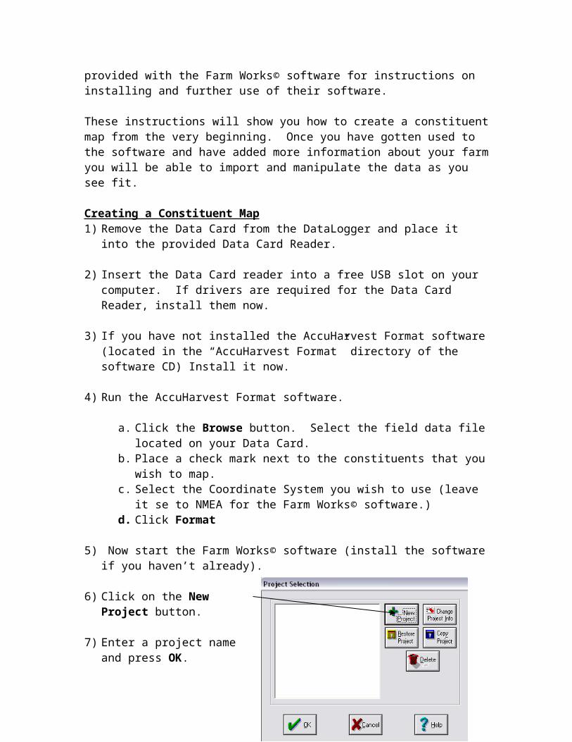
The mapping software included with the AccuHarvest is by Farm Works© and is a very powerful and useful software package. The instructions in this manual will only provide the information needed to create constituent maps from the data collected by the AccuHarvest. Please read the manuals provided with the Farm Works© software for instructions on installing and further use of their software.
These instructions will show you how to create a constituent map from the very beginning. Once you have gotten used to the software and have added more information about your farm you will be able to import and manipulate the data as you see fit.
Creating a Constituent Map1) Remove the Data Card from the DataLogger and place it into the provided Data Card
Reader.
2) Insert the Data Card reader into a free USB slot on your computer. If drivers are required for the Data Card Reader, install them now.
3) If you have not installed the AccuHarvest Format software (located in the “AccuHarvest Format” directory of the software CD) Install it now.
4) Run the AccuHarvest Format software.
a. Click the Browse button. Select the field data file located on your Data Card.b. Place a check mark next to the constituents that you wish to map.c. Select the Coordinate System you wish to use (leave it se to NMEA for the
Farm Works© software.)d. Click Format
5) Now start the Farm Works© software (install the software if you haven’t already).
6) Click on the New Project button.
7) Enter a project name and press OK.
8) Click on the project that you just created and select OK.
9) From the View menu select Layers and then Management.
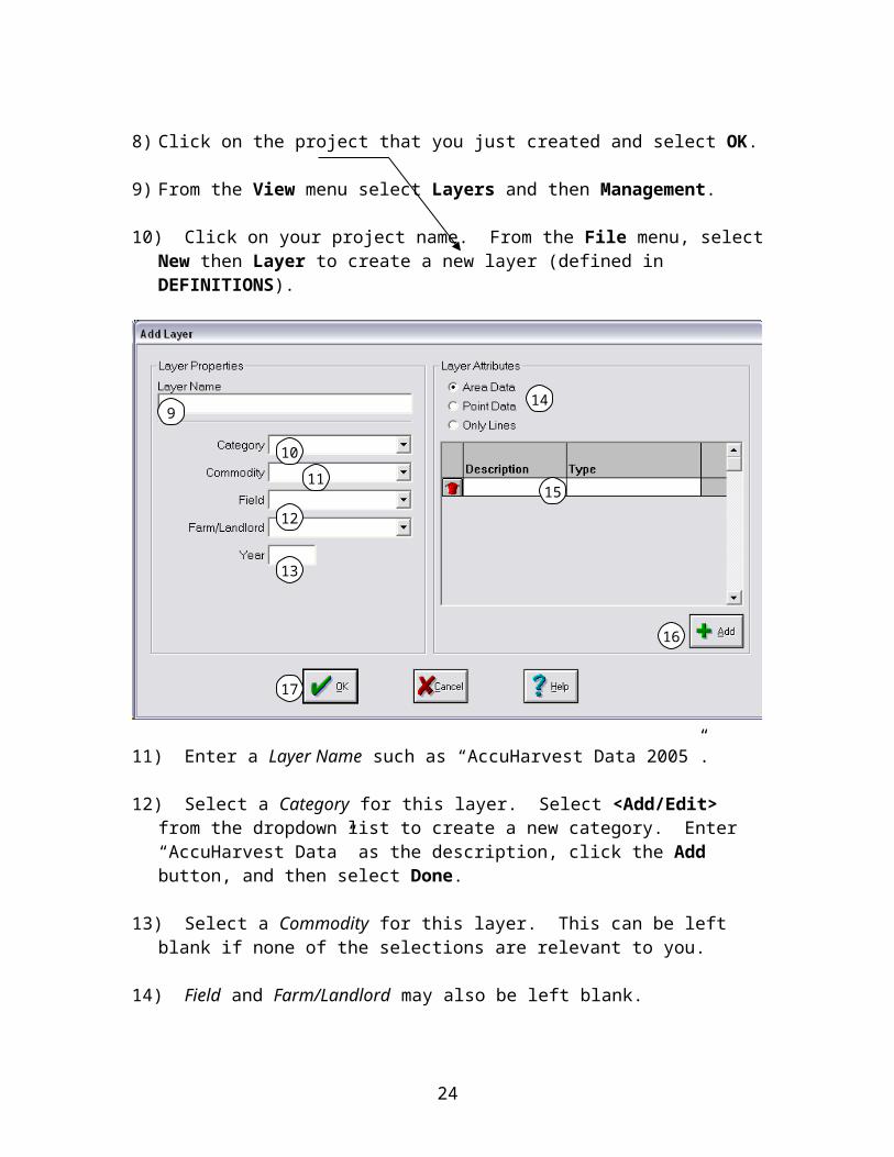
10) Click on your project name. From the File menu, select New then Layer to create a new layer (defined in DEFINITIONS).
16
11) Enter a Layer Name such as “AccuHarvest Data 2005”.
12) Select a Category for this layer. Select <Add/Edit> from the dropdown list to create a new category. Enter “AccuHarvest Data” as the description, click the Add button, and then select Done.
13) Select a Commodity for this layer. This can be left blank if none of the selections are relevant to you.
14) Field and Farm/Landlord may also be left blank.
15) Enter the Year in which the data was collected.
16) Select Point Data in the Layer Attributes section.
17) Under Description, enter the first constituent that you wish to map (“Protein CM” for example). Click on the white box under Type. Choose Number from the dropdown list that appears.
18) Use the Add button to add another constituent that you would like to create a map for. The AccuHarvest measures Protein CM, Moisture, Oil CM, and Starch CM (some products such as Wheat do not have an oil or starch calibration). For example, if you wish to create a map for Protein CM and Moisture you will need to click the Add button once.
17
9
10
11
12
13
14
15
16
17
19) Select the OK button and the layer will be created.20) Once you are back to the Layer Management screen you will see the newly created
layer on the left hand side. Select this layer and click on the Right Arrow Button to add this layer to your displayed layers. Then click Done.
21) Select Import from the File menu.
22) Select Generic Import from the File Type dropdown list.
23) Be sure the Import as Lines option is NOT selected.
24) Select the Browse button to choose the Import File to be imported. The file that you need is located on your Data Card Reader. Your computer treats the Data Card Reader like a separate drive. Find this “drive” when browsing for your file. Select the file that you wish to use (it should have the word formatted in the file name).
25) Use the Layers button to select the layer that you just created if it is not already selected.
26) Select the Import button. The Generic Import box will appear.
18

27) Under Import Desc. Enter “AccuHarvest Data” and select Save this format. This will save the work that we do here so that the next time you create a map all you will have to select is “AccuHarvest Data” from the Saved Imports dropdown list.
28) Select Tab from the Delimiter dropdown list.
29) Select NMEA from the Coord. Sys. Dropdown list.
30) In the Set Values by column, set all options to From File.
31) In the Position or Value column, select the following from the dropdown list:for LONGITUDE select Column 1for LATITUDE select Column 3
for E or W Longitude select Column 2for N or S Latitude select Column4
The next four columns represent your constituent data. The constituents will always be in the order:
Protein – Moisture – Oil – Starch
If you select to map Protein and Moisture, then Protein CM would be in Column 5 and Moisture would be in Column 6. If you selected to map just Oil CM, then Oil CM would be in Column 5. If you selected Protein CM, Moisture, and Starch CM, Protein CM would be in Column 5, Moisture would be in Column 6, and Starch CM would be in Column 7.
19
25
26
27
28 29
30
31
32) Once you have all of the columns selected, change the Number of Header Lines in File value to 1 (one).
33) Select the Import button. If the program encounters data that does not conform to the specifications (perhaps the Protein value gave a Too High warning, therefore the data in the file is replaced by a “N/A”) a warning message will be displayed. This warning will give you the option to continue or stop importing. It is best to try to continue importing and let the program ignore these lines.
34) Click the Done button to exit the Import box. The new layer will appear with all points colored gray.
You may now repeat this process if you have more than one file for the field you wish to map. Once you have all of the files imported, it is time to make a legend.
Making a Legend1) Select Layer Tools from the dropdown list at the top of the screen
2) Select the Edit Legend button in the toolbar. The Legend Properties box will appear.
20
3
4
5
6 & 7
8
9
10
11
3) Select <New> from the Current Legend dropdown list and enter a Legend Name (Protein CM for example).
4) Select the item to be used for the legend from the Data Item dropdown list (again, Protein CM for example).
5) Under the Ranges tab, select Equal Ranges. You may choose other ways of making your legend once you have become more familiar with this process.
6) Enter a number for the High Value of your legend. This should be a whole number that is near the highest recorded value for the field. If you do not know this value, you may select the Statistical button. This will show you the maximum and minimum values for the field. Once you have made note of these values, select the Equal Ranges button.
7) Enter a number for the Low Value. This should be a whole number that is near the lowest recorded value for the field.
8) Enter a value for spacing. Zeltex recommends 0.5 if the range from the minimum value to the maximum value is 6 or less. Otherwise choose 1.0.
9) Click on the Apply button to show your new settings in the grid to the left.
10) Select the Colors tab to assign the colors to the legend that you like best. Zeltex recommends that you choose the Wide option. Click on the Apply button again to see these changes.
11) When you are happy with the legend, select Record to save it and then select the Done button to display the map. The gray boxes on the map will now be colored.
12) To view the legend, select the View Legend button on the toolbar.
21
You may wish to view a more smoothed map. If this is the case, close the legend (you may view it again later) and follow these steps:
Creating a “Smoothed” Map1) Click on the Layers tab.
2) Double click on the Main Farming Layer to make it the active layer (it will move to the top of the list).
3) Select Mapping Tools from the dropdown list at the top of the screen.
4) Select the Multi Line button from the Mapping Tools toolbar.
5) Draw a line around your field. Left click with your mouse on a corner of the field to start the line. Left click again every where you want to make a corner. Once you have drawn a line completely around your field, right click with your mouse.
22
6) Select the Define Objects button from the Mapping Tools toolbar.
7) Left click inside the box that you just made. The Object Properties box should open.
If this does not open, then you probably did not completely close your box around your field. To fix this, click on the Corner button. Then click on the first and last lines that you drew. This will complete the corner. Now go back to step 6
8) In the Object Properties box enter a description (a field name or number for example) and then click OK.
9) Now go back to your created layer (AccuHarvest Data for example) by double clicking on the layer name.
10) Select Layer Tools from the dropdown list at the top of the screen then select the Smoothing button.
11) Select Smooth and Contour from the Method dropdown menu.
12) Select your field from the Field dropdown menu.
13) Change the grid size to a value that makes sense for your field. For a smaller field use a smaller number like 20, for a larger field you can use 50, 100, and so on. This is a value that you should adjust until you find results that you like.
23
14) Click on the Options button. Again, these are numbers that you need to adjust to your liking. For this example 20 points were used in calculation and points over 75 feet away were ignored. Select OK when you are done.
15) Select OK. The mouse cursor will now have grid marks next to it. Click on one of the corners of your field. The software will then smooth your map.
To revert back to the original map, select the Display button from the Layer Tools toolbar. Then select <Base Data> from the Data View dropdown list and select OK.
If you wish to know the exact coordinates of anywhere on the map, click on the Coordinates button from the Layer Tools toolbar.
24