accessory kit installation instructions - upgnet · unitary products group accessory kit...
TRANSCRIPT

ACCESSORY KIT INSTALLATION INSTRUCTIONSNATURAL GAS HIGH ALTITUDE CONVERSION KITS - MODELS 1HA0454 and 0455
FOR SINGLE PACKAGE EQUIPMENT GAS/ELECTRIC AIR CONDITIONERS1HA0454 (For ZXG04, 05, 06, 07 and ZYG04, 05, 06 Unit Models Only)
1HA0455 (For ZXG08, 09, 12, 14 and ZYG07, 08, 09, 12 Unit Models Only)
1104798-UAI-B-0714
SCOPE
This accessory provides the parts to operate a natural gasfurnace between 2,000 and 10,000 feet for U.S. installation.In Canada, this kit is certified for installations from 2,000 to4,500 feet (610 TO 1829 meters). The installation instructionssupplied with the unit is to be used for all other aspects of theinstallation including setting the input rate.
This conversion kit shall be installed by a qualifiedservice agency in accordance with the manufac-turer’s instructions and all applicable codes andrequirements of the authority having jurisdiction. Ifthe information in these instructions is not followedexactly, a fire, explosion or production of carbonmonoxide may result causing property damage,personal injury or loss of life. The qualified serviceagency is responsible for the proper installation ofthis kit. The installation is not proper and completeuntil the operation of the converted appliance ischecked as specified in the manufacturer’s instruc-tions supplied with the kit.
For U.S. units, installation must be made in accor-dance with American National Standard NationalFuel Gas Code, ANSI Z223.1 – latest edition,unless superseded by local codes. For Canadianinstallations, the conversion shall be carried out inaccordance with the requirements of the provi-sional authorities having jurisdiction and in accor-dance with the CAN1-B149.1 installation codes.
Improper installation, adjustment, service or main-tenance can cause injury or property damage.Therefore, only a qualified installer or qualified ser-vice personnel should perform this conversion.
If the unit is connected to power sources, makesure that all electrical power to the unit has beendisconnected and the gas supply to the unit hasbeen shut off before proceeding.
TABLE 1: PARTS IN KIT 1HA0454
ITEM QTY. PART NO. DESCRIPTION
1 3 1102370 Burner Orifice No. 31
2 3 1102933 Burner Orifice No. 32
3 3 1102934 Burner Orifice No. 33
4 3 1102935 Burner Orifice No. 34
5 3 1102936 Burner Orifice No. 35
6 3 1102937 Burner Orifice No. 36
7 3 1102938 Burner Orifice No. 37
8 3 1102939 Burner Orifice No. 38
9 3 1102940 Burner Orifice No. 39
10 3 1102971 Burner Orifice No. 40
11 3 1102972 Burner Orifice No. 41
12 3 1102973 Burner Orifice No. 42
13 3 1102974 Burner Orifice No. 43
14 2 1102975 Burner Orifice No. 44
15 1 10561 LABEL - CONVERSION
16 1 11005 OVERLAY,LAMINATE R:A
17 1 1104798 ACCESSORY INSTALLATION INSTRUCTION
TABLE 2: PARTS IN KIT 1HA0455
ITEM QTY. PART NO. DESCRIPTION
1 5 1102370 Burner Orifice No. 31
2 5 1102933 Burner Orifice No. 32
3 5 1102934 Burner Orifice No. 33
4 5 1102935 Burner Orifice No. 34
5 5 1102936 Burner Orifice No. 35
6 3 1102937 Burner Orifice No. 36
7 3 1102938 Burner Orifice No. 37
8 3 1102939 Burner Orifice No. 38
9 1 10561 LABEL - CONVERSION
10 1 11005 OVERLAY,LAMINATE R:A
11 1 1104798 ACCESSORY INSTALLATION INSTRUCTION
Unitary Products Group
1104798-UAI-B-0714
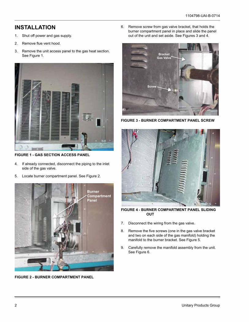
INSTALLATION1. Shut off power and gas supply.
2. Remove flue vent hood.
3. Remove the unit access panel to the gas heat section. See Figure 1.
FIGURE 1 - GAS SECTION ACCESS PANEL
4. If already connected, disconnect the piping to the inlet side of the gas valve.
5. Locate burner compartment panel. See Figure 2.
FIGURE 2 - BURNER COMPARTMENT PANEL
6. Remove screw from gas valve bracket, that holds the burner compartment panel in place and slide the panel out of the unit and set aside. See Figures 3 and 4.
FIGURE 3 - BURNER COMPARTMENT PANEL SCREW
FIGURE 4 - BURNER COMPARTMENT PANEL SLIDING OUT
7. Disconnect the wiring from the gas valve.
8. Remove the five screws (one in the gas valve bracket and two on each side of the gas manifold) holding the manifold to the burner bracket. See Figure 5.
9. Carefully remove the manifold assembly from the unit. See Figure 6.
BurnerCompartmentPanelCCCP
BracketGas Valve
Screwww
2 Unitary Products Group

1104798-UAI-B-0714
FIGURE 5 - 5 SCREWS HOLDING MANIFOLD BRACKET IN PLACE
10. Remove the main burner orifices from the manifold and discard them.
FIGURE 6 - MANIFOLD REMOVED
11. From Tables 3 and 4, select the orifice size necessary for your unit at elevation.
Remove ScrewscrRemove Sce SSSc
TABLE 3: KIT 1HA0454
Unit Model Heating Option (Mbh)
Number of Orifice
Elevation (ft.)2000 3000 4000 5000 6000 7000 8000 9000 10000
Derate %4 8 12 16 20 24 28 32 36
Orifice numberZXG04,05,06, ZYG04,05,06 L (56)
240 41 41 421 42 43 43 44 44
ZXG04,05,06,07, ZYG04,05,06 D (70) 36 36 371 37 38 39 40 41 42ZXG04,05,06, ZYG04,05,06 M (90)
3
38 39 39 401 41 42 42 43 43ZXG04,05,06,07, ZYG04,05,06 E (112) 33 34 35 35 361 36 37 38 40
ZXG05,06, ZYG05,06 N (118) 32 33 33 34 351 36 36 37 39ZXG05,06,07, ZYG05,06 F (145) - 31 31 311 31 32 32 33 34
1. In Canada, this kit is certified for installation from 2,000 to 4,500 feet (610 to 1829 meters) when the indicated orifice is installed and the manifold pressure is adjusted to provide a 10% derate. After this initial derate a 4 % derate is required per 1000 ft. of altitude above 4500 ft.
TABLE 4: KIT 1HA0455
Unit Model Heating Option (Mbh)
Number of Orifice
Elevation (ft.)2000 3000 4000 5000 6000 7000 8000 9000 10000
Derate %4 8 12 16 20 24 28 32 36
Orifice numberZXG08,09, ZYG08,09 D (125)
332 32 32 33 341 35 36 37 38
ZYG07 E (125)ZYG07 F (150) - 31 31 311 31 32 32 33 34
ZXG08,09, ZYG08,09 E (180)4 - 31 31 321 32 33 33 34 35
ZXG12,14, ZYG12 D (180)ZXG08,09, ZYG08,09 F (220)
5- 31 31 321 32 33 33 34 35
ZXG12,14, ZYG12 E (220)ZXG12,14, ZYG12 F (250) - 31 31 311 31 32 32 33 34
1. In Canada, this kit is certified for installation from 2,000 to 4,500 feet (610 to 1829 meters) when the indicated orifice is installed and the manifold pressure is adjusted to provide a 10% derate. After this initial derate a 4 % derate is required per 1000 ft. of altitude above 4500 ft.
Unitary Products Group 3
1104798-UAI-B-0714
12. Remove the appropriate orifices from the kit and install them in the gas manifold and securely tighten them. Dis-card all remaining orifices in the kit.
13. Replace the manifold in the unit securing the assembly to the burner bracket and gas valve bracket with the five screws removed earlier. The burner orifices should fit inside the orifice retention ring in the back of each burner.
14. Slide burner compartment panel into place and screw it to the gas valve bracket.
15. Reconnect the gas piping to the inlet of the gas valve.
16. Reattach the wiring to the gas valve.
17. Mark the appropriate data (burner orifice size, manifold pressure and input capacity) on the conversion label pro-vided in the kit and install it adjacent to the unit name plate.
18. Apply the laminate overlay included in the kit over the conversion label.
19. Turn on the gas supply.
20. Check for leaks at all gas fittings. Repair all leaks and recheck for leaks.
TESTS AND ADJUSTMENTS
All adjustments and testing must be performed at the time ofconversion.
1. Connect a manometer to the manifold side of the gas valve in order to measure manifold pressure.
2. Turn the gas valve to the ON position. Make sure the electrical disconnect is in the OFF position.
3. For two stage units, connect a jumper between terminal "R" and "W1" on the UCB and another jumper from "R" to "W2" on the UCB to simulate a call for heat on high fire. For single stage units, connect a jumper between terminal “R” and “W1” on the UCB.
4. Energize the power supply to the disconnect switch.
5. The combustion blower should start and, after the pre-purge cycle, the igniter should begin sparking. Because there may still be some air in the gas supply line, the unit may require several attempts to light.
6. Once the unit lights, adjust the manifold pressure to achieve the appropriate derate for altitude by turning the adjustment screw on the gas valve adjacent to the "HI" marking on the valve. Single stage gas valves will not have a “HI” marking as there is only one adjustment screw. On two stage units, always adjust the high fire setting prior to adjusting the low fire setting.
7. Check for gas leaks, especially in the following locations: gas valve inlet and outlet, gas supply union, and main burner orifices where they screw into the manifold using a soap and water leak detection solution.
8. Observe several ignition cycles. The burners should light without delayed ignition or flashback and there should be no impingement of the flame on the metal panel sur-rounding the entrance to the heat exchanger tubes.
NOTE: For single stage units, skip to step 14.
9. Turn off electrical power to the unit.
10. Remove the jumper between "R" and "W2". This will sim-ulate a call for first stage heat.
11. Restore electrical power to the unit.
12. At the end of the pre-purge period, the unit should light on high fire. It will stay on high fire for approximately one minute. At the end of this time period the unit will switch to low fire.
13. Set the low fire manifold pressure to achieve the appro-priate derate for altitude by turning the screw adjacent to the "LO" marking on the valve.
14. Shut off the gas supply and electrical supply to the unit.
15. Turn the gas valve Switch to "OFF".
FIRE OR EXPLOSION HAZARDFailure to follow the safety warning exactly could result in serious injury, death or property damage.Never test for gas leaks with an open flame. Use acommercially available soap solution made specif-ically for the detection of leaks to check all connec-tions. A fire or explosion may result causingproperty damage, personal injury or loss of life.
FIRE OR EXPLOSION HAZARDFailure to follow the safety warning exactly could result in serious injury, death or property damage.Never test for gas leaks with an open flame. Use acommercially available soap solution made specif-ically for the detection of leaks to check all connec-tions. A fire or explosion may result causingproperty damage, personal injury or loss of life.
4 Unitary Products Group

16. Remove the pressure tap on the outlet side of the valve and replace the plug.
17. Remove the jumper.
NOTE: To set the rate on the unit, consult the installationinstructions supplied with the unit.
18. Turn the gas valve Switch to "ON".
19. Replace the unit gas heat access panel.
20. Replace the flue vent hood.
21. Turn electrical supply on to the unit.
Subject to change without notice. Printed in U.S.A. 1104798-UAI-B-0714Copyright © August 11, 2014 by Johnson Controls, Inc. All rights reserved. Supersedes: 1104798-UAI-A-0314
York International Corporation5005 York Drive
Norman, OK 73069