accessories - hutton communications · • base transceiver station ... andrew offers a...
TRANSCRIPT

Accessories FOR CABLE INSTALLATION
NORTH AMER ICA PROduCT SE L ECT ION Gu IdE 2009


Table of Contents
1Andrew • www.andrew.com
A Cable Hoisting and Attachment
B Weatherproofing
C Cable Entry
D Grounding Kits
E Grounding Bars
F Arrestor Plus® Surge Arrestors
Introduction
Cable Installation Accessories
Cable Hoisting and Attachments ................................................. 8
Weatherproofing ....................................................................... 18
Cable Entry ............................................................................... 21
Installation Aids......................................................................... 24
Lightning Protection
Grounding Kits .......................................................................... 32
Grounding Bars ......................................................................... 36
Surge Arrestors ........................................................................ 39
Appendixes
Appendix 1: Quarterwave Stub Surge Arrestors ....................... 42
Appendix 2: Gas Tube Surge Arrestors .................................... 45
Appendix 3: dc Passing T-Series Surge Arrestors .................... 48
Appendix 4: Lightning Strike Probability .................................. 49
Appendix 5: Hanger Spacing Guidelines .................................. 50
Appendix 6: Hardware and Accessory Consolidation Reference ..................................................57

Whether you’re a wireless network operator, original equipment manufacturer, distributor, integrator or installer, you need the right solutions—solutions that help you stay one step ahead of technology and the costs of keeping up. Solutions that help you stay ahead of the game. Andrew delivers those solutions for traditional wireless networks, third-generation technologies, triple-play (voice, data, video) services, as well as specialized applications for microwave communication systems.
Our evolution begins with you.
Andrew • www.andrew.com2

Some technologies evolve in small increments; others evolve seemingly overnight. Andrew is always at the forefront, supporting the evolution on behalf of you, our customer. Over the years, Andrew has evolved too, from our humble beginnings in 1937 to our position today as a CommScope company and global leader.
Our evolution has come full circle today, as Andrew is committed to providing one complete source for man-aging the entire lifecycle of a wireless network. We design, manufacture, and deliver innovation for:
• Top-of-the-tower base station antennas
• Transmission line systems• Microwave backhaul solutions• Base transceiver station (BTS)
radio equipment• Coverage and capacity solutions• Radio frequency (RF) signal
distribution products• Network optimization software• Integrated cabinet solutions
We serve our customers from facili-ties in 35 countries, including multiple manufacturing plants in 10 countries. And many of our customer relationships span 25 years or more. It’s a strong testament to what we can accomplish together.
Just look for the distinctive symbol that has been synonymous with advanced connectivity for more than 70 years: the Andrew flash.
The evolution of change.
3Andrew • www.andrew.com

Andrew • www.andrew.com4
Product ResourceYour Source for Andrew Product Information
Visit the Product Resource at www.commscope.com for in-depth, up-to-the-minute information about Andrew products. The Product Resource provides detailed product specifications, images, installa-tion instructions, links to related products, product comparisons, and more. It includes new products, information on discontinued products and their replacements, and easy-to-use calculators.
You decide how to view information—online, as a realtime customizable .pdf file, bundled .zip file, email link, or spreadsheet.
Visit the Product Resource often—it’s your source for Andrew product information: http://awapps.commscope.com/catalog/catalog.aspx
OnePackSM Site KitsThe Answer for More Efficient System Build-outs
Today’s global build-out demands new solutions that speed system deployment and simplify supply chain management. To help system managers better achieve these goals, Andrew offers kits for wire-less RF communications systems sites. OnePack Site Kits provide the critical components in easy to order, easy to manage packages. System designers and managers can be confident of shortened project planning and execution cycles, improved efficiency, and dependable system performance.
Customer Support Center (CSC)Service Around the Clock, Around the World
Contact the Andrew Customer Support Center for:
d Technical supportd Order statusd Coordinating product service, repairs, or replacementd Product informationd Replacement materials
Call toll free from:
North America 1-800-255-1479 Fax 1-800-349-5444
International: United Kingdom 0800-250055 Australia 1800-803 219 New Zealand 0800-441-747 Call from other areas: +1 708-873-2307
Services

5Andrew • www.andrew.com 5
Joliet, Illinois USA
Lochgelly, Scotland
Sorocaba, Brazil
Suzhou, China
For more information visit our Web site at: www.andrew.com
Registration is available online or call: +1-779-435-6231
Andrew Institute provides technicians with the top-quality, specialized training they need to optimize communications systems performance and reliability.
d Free training at Andrew facilities
d Comprehensive, hands-on instruction
d The latest Andrew products, installation methods, and theories
d Shared expertise
d Sharpen your skills, learn new techniques and see the latest product innovations
d 2-Year Certification after completed Andrew Institute coursework
Courses Offered Teletilt® Systems — Remote Controlled Variable Electrical Downtilt Antennas
Covering topics from antenna fundamentals, hands-on installation of actuator, data cables, and control system, attendees will walk away with a better understanding of Andrew Base Station products.
HELIAX® Connector Attachment Training
Ideal for those who require assistance with fitting cables and connectors or would benefit from expanded technical training covering all aspects of HELIAX transmission line installation and latest techniques.
Terrestrial Microwave Systems Installation Training
Improve the efficiency and effectiveness of your Terrestrial Microwave (TMW) systems with free specialized training on all aspects of installing and testing Andrew products.
VSWR Fundamentals
During the VSWR Fundamentals course attendees will learn definitions, testing guidelines, and plot/sweep interpretation.

Selection Guide
Elements of a Cable Mounting and Protection System
Andrew • www.andrew.com6
Once you’ve selected the cable and connectors for your system, the cable mounting and protection system must be planned. Andrew offers a comprehensive line of installation accessories and lightning protection systems to help you realize your communications system’s full potential.
Hoisting Grips
Select a hoisting grip to safely raise the cable and hold it during hanger attachment. In some cases, a hoisting grip must also be used with a calibrated clamp, available from Andrew, to provide permanent support for the cable.
Hangers
The type or shape of the structure, the space available for cable attachment, the type of environment the system will be exposed to, and the ease of installation or maintenance are key considerations. Many hanger options are available, and many variables have tradeoffs that affect total hanger system cost. The table on page 17 will help you select the best hangers for your system and budget.
Weatherproofing
Weatherproofing keeps connector interfaces tight and adds an additional layer of protection against the environment. Andrew offers three types of weatherproofing. A standard weather-proofing kit provides universal coverage and uses butyl and vinyl tapes to wrap connector surfaces. Our 3M™ Cold Shrink™ weatherproofing kit uses a self-shrinking technology to reduce installation time. New WeatherShield™ enclosures seal and protect connectors for the environment in seconds.
Cable Entry
The final step in a base station installation is to bring the cable into the building or radio cabinet. Two basic types of cable entry systems are available: a standard building entry, and an integrated system that combines cable entry and lightning surge suppression into one efficient system.
Grounding Kits
A grounding kit diverts transient currents from lightning off the transmission line to an earth grounding system to prevent damage to cable and radio equipment. A typical installation uses three grounding kits: near the top of the main feeder cable, at the bottom of the main feeder prior to the horizontal run, and just prior to the cable entering the building. Andrew offers three kit types to meet the requirements of your system and budget.
Surge Arrestors
Andrew Arrestor Plus® surge arrestors provide the last stage of an effective lightning protection system. Install them to divert lightning transients off the inner conductor of your coaxial cable before they reach your radio equipment. Select from a variety of surge arrestors to meet your exact requirements.

( Cable Hoisting and Attachment
( Weatherproofing
( Cable Entry
( Installation Aids
CA
BLE INSTA
LLATION
AC
CESSO
RIES

Cable Installation Accessories
Cable Hoisting and Attachment
Andrew • www.andrew.com8
Support/Hoisting GripSafer, Faster Cable Hoisting
Lift and support cable in your monopole or on your tower faster and more safely and without the threat of slippage. Our one-piece grip and locking clamp speed and simplify installation by eliminating time consuming lacing.
Use at 200 ft (60 m) intervals to raise cable and provide permanent cable support. Basic kit includes one grip and one support clamp. Support clamps are also available in kits of 10. Installation tool is required.
Part Number Part Number
Support Grip Support Clamp Cable Size Cable Type
F1SGRIP F1SGRIP-1IK 1/4" FSJ1L1SGRIP L1SGRIP-1IK 1/4" LDF1L2SGRIP L2SGRIP-2IK 3/8" LDF2, FXL-500F2SGRIP F2SGRIP-2IK 3/8" FSJ2C2SGRIP C2SGRIP-2IK 3/8" CNT-400L4SGRIP L4SGRIP-4IK 1/2" LDF4, FXL-540F4SGRIP F4SGRIP-4IK 1/2" FSJ4L45SGRIP L45SGRIP-45IK 5/8" LDF4.5L5SGRIP L5SGRIP-5IK 7/8" LDF5, VXL5, AVA5, FXL-780L6SGRIP L6SGRIP-6IK 1-1/4" LDF6, VXL6, AVA6, FXL-1480L7SGRIP L7SGRIP-7IK 1-5/8" LDF7, VXL7, AVA7, FXL-1873L12SGRIP L12SGRIP-12IK 2-1/4" LDF123CCGRIP — — RET cablePart Number DescriptionSG-IT Support Clamp Installation Tool
Standard Hoisting Grip For Transmission Line Installation
Use at 200 ft (60 m) intervals to raise cable on tower. Use with addi-tional support clamp to achieve optimum cable grip.
Part Number Part Number
Hoisting Grip Optional Support Clamp Cable Size
43094 L4SGRIP-4IK 1/2"29958 L45SGRIP-45IK 5/8"19256B L5SGRIP-5IK 7/8"29961 L6SGRIP-6IK 1-1/4"24312A L7SGRIP-7IK 1-5/8"31535 L12SGRIP-12IK 2-1/4"26985A — 3"34759 — 4"31031-1 — 5"
Use the support/hoisting grip whenever possible. Rely on the standard, lace up hoisting grip only when connectors are pre-attached or you have to place a grip in the middle of a cable run over 200 ft.
TIP!
TIP!

Cable Installation Accessories
Cable Hoisting and Attachment
9Andrew • www.andrew.com
Snap-In Hangers Attachment with No Hardware!
Andrew Snap-In hangers provide quick and easy attachment in all types of weather. The hangers snap directly into holes in the tower support members. Installation time and costs are substantially reduced. These hangers feature cable gripping tabs to prevent cable slippage, and are constructed of heavy gauge stainless steel for high strength and excel-lent corrosion resistance. Waveguide versions include a heavy UV resis-tant rubber insert to secure the elliptical waveguide.
Part Number Description206706A-6 For 5/8 in cable206706A-5 For 2-1/4 in cableEWSH-52 For EW52 waveguideEWSH-63 For EW63 waveguideEWSH-64 For EW64 waveguideEWSH-77 For EW77 waveguideEWSH-90 For EW90 waveguideEWSH-127A For EW127A waveguideEWSH-132 For EW132 waveguideEWSH-180 For EW180 waveguideEWSH-220 For EW220 waveguideEWSH-240 For EW249 waveguide
SnapStak™ HangersNew design increases stack height
SnapStak hangers have become the industry standard for maximizing space utilization on crowded towers and now that utility is further expanded with the next generation that provides the ability to add an additional cable run to the stack. This new capability is enabled by a support beam that is inserted into the base of each hanger giving the strength to handle an additional cable run. Sold in kits of 10.
SnapStak hangers can be snapped into 3/4 inch through holes in the tower’s cable ladder or used in conjunction with a variety of mounting accessories for rooftops, buildings, and water towers. Stainless steel construction of SnapStak hangers provides exceptional integrity in corrosive environments and extreme weather conditions.
SnapStak Hanger benefits:
d Fits corrugated and smoothwall cables
d Saves space on crowded towers, rooftops, and other structures
d Installs 1-1/4 inch and 1-5/8 inch cables three high
d Installs 1/2 inch and 7/8 inch cables four high
d Reduces material and installation costs
d Fast, easy attachment
Part Number Cable Size DescriptionSSH-12-4 1/2" SnapStak Hanger Kit for 1/2 in coaxial
cable, with reinforcement bar, four stack capability
SSH-78-4 7/8" SnapStak Hanger Kit for 7/8 in coaxial cable, with reinforcement bar, four stack capability
SSH-114-3 1-1/4" SnapStak Hanger Kit for 1-1/4 in coaxial cable, with reinforcement bar, three stack capability
SSH-158-3 1-5/8" SnapStak Hanger Kit for 1-5/8 in coaxial cable, with reinforcement bar, three stack capability
SSHR-10 1/2"–1-5/8" SnapStak Hanger Reinforcement Bar, kit of 10
SSHAK-3812 SnapStak hanger kit for RET cable or 3/8 in braided cable
SSHA-38 Insert, adapts 1/2 in snap in hanger to RET cable or 3/8 in braided cable
United States Patents: 6,345,543, 6,899,305, and 6,161,804. Other patents pending.
SnapStak hanger kits include reinforcer bar to enable higher stack height.

Cable Installation Accessories
Cable Hoisting and Attachment
Andrew • www.andrew.com10
Snap-In Tower StandoffsFor mounting snap-in hangers to round support members. Adapter is designed with 3/4 inch pre-punched hole. Adapter provides 2-1/2 in (60 mm) standoff. All parts are stainless steel or galvanized, kit of 10.
Part Number Member Diameter, in (mm)STS3-12 1–2 (25–50)STS3-23 2–3 (50–75)STS3-34 3–4 (75–100)STS3-45 4–5 (100–125)
SnapStak™ Hanger ToolSpecially designed pliers make installation and removal of SnapStak snap-in hangers extremely easy. The spring loaded pliers are designed with a hook that holds and spreads the hanger open to slip easily over the cable. Serrated pads then squeeze the hanger together for effortless insertion into the mounting structure. Insulated handle and a lanyard hole make it easy to hang on to.
Part Number Description SHT-4 SnapStak hanger tool, quantity 1
Part Number DescriptionUA-3 Universal snap-in adapter, kit of 10
Universal Angle Adapter InsertInsert transitions the universal adapter’s 3/4 inch to a 3/8 inch hole diameter, which allows the use of standard hangers.
Part Number DescriptionUAAI Universal angle adapter Insert, kit of 10
Each part sold separately
( UA-3
( UAAI
Universal Snap-In AdapterThe universal snap-in adapter is a versatile device for securing coaxial cable hangers to structures such as communications towers, rooftops, buildings and water towers.
The universal snap-in adapter secures coaxial cable to any round or angle tower members where pre-punched holes are not easily acces-sible. The adapter has a pre-punched 3/4 inch hole that allows the installer to mount cable hangers such as Andrew SnapStak™ snap-in hangers to wireless communications towers or other structures. Stainless steel construction for long life.
Universal Adapter Applications
Cable Installation Accessories
Cable Hoisting and Attachment
11Andrew • www.andrew.com
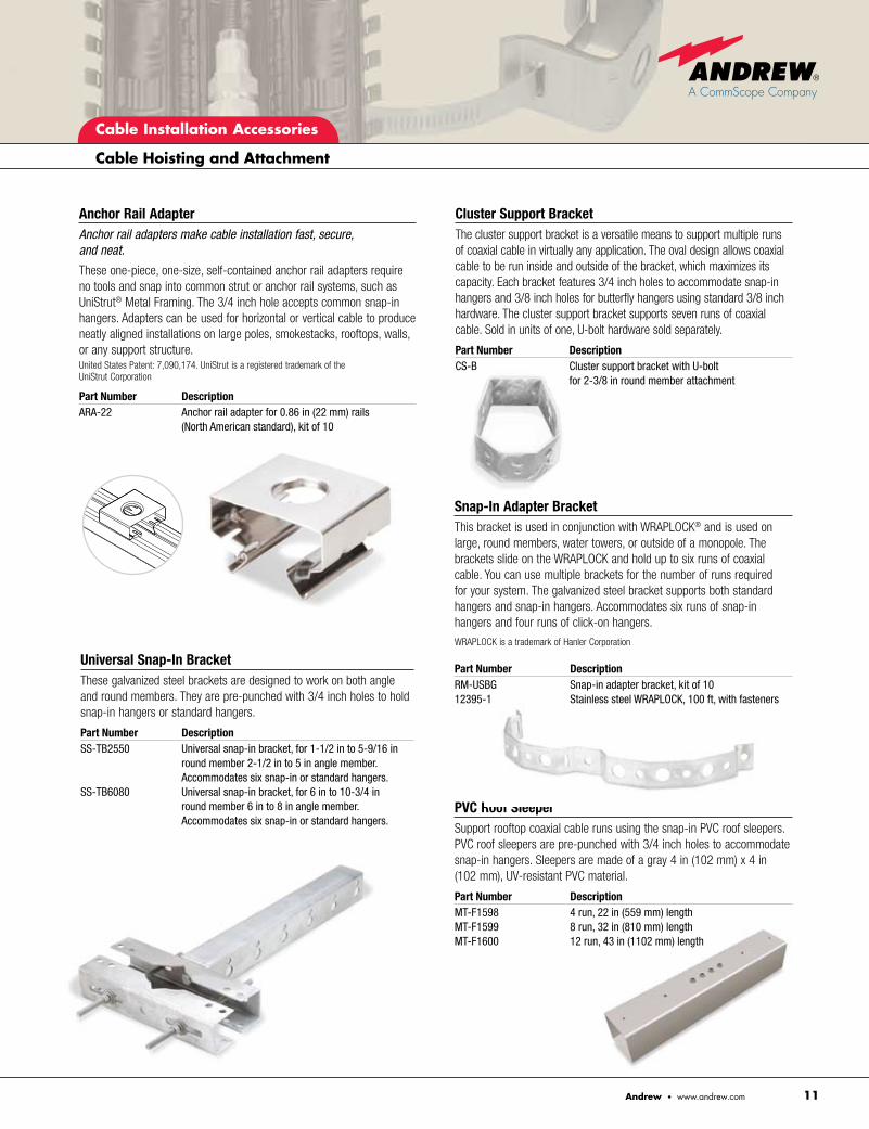
Cluster Support BracketThe cluster support bracket is a versatile means to support multiple runs of coaxial cable in virtually any application. The oval design allows coaxial cable to be run inside and outside of the bracket, which maximizes its capacity. Each bracket features 3/4 inch holes to accommodate snap-in hangers and 3/8 inch holes for butterfly hangers using standard 3/8 inch hardware. The cluster support bracket supports seven runs of coaxial cable. Sold in units of one, U-bolt hardware sold separately.
Part Number Description CS-B Cluster support bracket with U-bolt for 2-3/8 in round member attachment
PVC Roof SleeperSupport rooftop coaxial cable runs using the snap-in PVC roof sleepers. PVC roof sleepers are pre-punched with 3/4 inch holes to accommodate snap-in hangers. Sleepers are made of a gray 4 in (102 mm) x 4 in (102 mm), UV-resistant PVC material.
Part Number DescriptionMT-F1598 4 run, 22 in (559 mm) lengthMT-F1599 8 run, 32 in (810 mm) lengthMT-F1600 12 run, 43 in (1102 mm) length
Snap-In Adapter BracketThis bracket is used in conjunction with WRAPLOCK® and is used on large, round members, water towers, or outside of a monopole. The brackets slide on the WRAPLOCK and hold up to six runs of coaxial cable. You can use multiple brackets for the number of runs required for your system. The galvanized steel bracket supports both standard hangers and snap-in hangers. Accommodates six runs of snap-in hangers and four runs of click-on hangers.
WRAPLOCK is a trademark of Hanler Corporation
Part Number DescriptionRM-USBG Snap-in adapter bracket, kit of 1012395-1 Stainless steel WRAPLOCK, 100 ft, with fasteners
Universal Snap-In BracketThese galvanized steel brackets are designed to work on both angle and round members. They are pre-punched with 3/4 inch holes to hold snap-in hangers or standard hangers.
Part Number DescriptionSS-TB2550 Universal snap-in bracket, for 1-1/2 in to 5-9/16 in
round member 2-1/2 in to 5 in angle member. Accommodates six snap-in or standard hangers.
SS-TB6080 Universal snap-in bracket, for 6 in to 10-3/4 in round member 6 in to 8 in angle member. Accommodates six snap-in or standard hangers.
Anchor Rail AdapterAnchor rail adapters make cable installation fast, secure, and neat.
These one-piece, one-size, self-contained anchor rail adapters require no tools and snap into common strut or anchor rail systems, such as UniStrut® Metal Framing. The 3/4 inch hole accepts common snap-in hangers. Adapters can be used for horizontal or vertical cable to produce neatly aligned installations on large poles, smokestacks, rooftops, walls, or any support structure.United States Patent: 7,090,174. UniStrut is a registered trademark of the UniStrut Corporation
Part Number DescriptionARA-22 Anchor rail adapter for 0.86 in (22 mm) rails (North American standard), kit of 10

Cable Installation Accessories
Cable Hoisting and Attachment
Andrew • www.andrew.com12
Angle Adapter Attachment
Ceiling Adapter Attachment
Part Number Attachment Hardware243684 Compact angle adapter, see page 15 for details244350 Ceiling adapter, kit of 10Round member adapter (various sizes) see page 15
Round Member Attachment
Flat Member Attachment
Click-On HangersClick-On Hangers—Install Cable with One Easy “Click”
Stackable click-on hangers install in just minutes and provide a perfect fit that gives your telecommunications system a compact, orderly cable installation, especially in confined spaces.
Available in either single or double versions, click-on hangers are manufactured of tough UV-resistant material and set the standard for durability, simplicity of installation, and cost effectiveness. They are attached with threaded rod (sold separately) and can be stacked up to three high. Fits corrugated and smoothwall cables. United States Patent: 5794897.
Double Single
Part Number Part Number DescriptionL4CLICK L4SCLICK Click-on hanger for 1/2 in coaxial
cable, kit of 10L45CLICK — Click-on hanger for 5/8 in coaxial
cable, kit of 10L5CLICKB L5SCLICKB Click-on hanger for 7/8 in coaxial
cable, kit of 10L6CLICK L6SCLICK Click-on hanger for 1-1/4 in coaxial
cable, kit of 10L7CLICK L7SCLICK Click-on hanger for 1-5/8 in coaxial
cable, kit of 10
Snap-In Adapter BlockThis snap-in adapter block is designed to accommodate a snap-in hanger on each side of the block. You can attach this to the tower with our standard angle adapters or tower standoffs. Stainless steel construction.
Part Number DescriptionSA-38 Snap-in adapter block, kit of 10

Cable Installation Accessories
Cable Hoisting and Attachment
13Andrew • www.andrew.com
Click-On Hanger Hardware KitsClick-on hanger attachment hardware is constructed of 3/8 inch stainless steel for durability. Select hardware length according to planned hanger stack height. Each kit contains 10 threaded rods, 30 nuts, 40 flat washers and 20 lock washers. Note: Click-on hangers accommodate two runs of cable and can be stacked up to three deep to handle up to six runs.
Part Number Stack Height Cable Size Rod Length (# of hangers) in (mm)
Imperial
243095-9 1 1/2" or 7/8" 3.75 (95)243095-5 2 1/2" or 7/8" 5.40 (137)243095-1 3 1/2" or 7/8" 7.00 (177)243095-10 1 1-1/4" or 1-5/8" 4.75 (121)243095-6 2 1-1/4" or 1-5/8" 7.25 (184)243095-2 3 1-1/4" or 1-5/8" 9.75 (248)
Miniature Click-On HangersFast, easy installation for small cables
Now installing small cables into hangers is accomplished in one easy click with miniature click-on hangers.
Each compact, miniature click-on hanger accommodates two runs of cable. Miniature click-on hangers are compact and stackable, making it easy to install several runs of cable in confined spaces.
Miniature click-on hangers are cost effective and durable. With flexible gripping ribs, the hanger provides secure support on a range of cable sizes, and indexing on the hanger body helps align cables during installation.
Specifically designed to accommodate small corrugated coaxial cables, elliptical waveguide, and braided cable runs, miniature click-on hangers provide a perfect fit for your installation. Hangers are packed in kits of 10. Attachment hardware, made of anti-corrosion coated metal for long service life, is sold separately in kits of 10.
United States Patent: 7,007,900.
Select hardware by intended hanger stack height.
Part Number Description68MCLICK Click-on hangers for 6–8 mm cable; FSJ1A, CNT-240, CNT-300912MCLICK Click-on hangers for 9–12 mm cable; LDF1, EFX2, FSJ2, LDF2, CNT-400, EW3801316MCLICK Click-on hangers for 13–16 mm cable; FSJ4, LDF4-50A, CNT-500, CNT-600
Part Number Description252026-10KT Mini angle adapters, M8 tap252027-10KT Single stack hardware for mini click-on hangers, M8 thread252028-10KT Double stack hardware for mini click-on hangers, M8 thread 252029-10KT Triple stack hardware for mini click-on hangers, M8 thread
Multi-run hangers are the best choice for installing cables where space is very limited on crowded towers.
TIP!
TIP!

Cable Installation Accessories
Cable Hoisting and Attachment
Andrew • www.andrew.com14
Standard HangersStandard Hangers and Hardware—For Security and Flexibility
Standard hangers are designed to attach smoothwall and corrugated coaxial cables and waveguide securely to just about any type of support structure. The clamp locking bolt and nut are pre-assembled and capti-vated to minimize installation labor. They are drilled for 3/8 inch or M10 mounting hardware and feature slots for round member adapter clamps. See pages 15–17 for accessories to adapt these hangers to most tower configurations.
Please refer to Appendix 5 for specific recommendations.
Hanger Part Number Cable Size Photo Reference43211A 3/8" A43211A 1/2" A42396A-9 5/8" B42396A-5 7/8" B42396A-1 1-1/4" B42396A-2 1-5/8" B42396A-4 2-1/4" B31766A-11 3" C31766A-10 4" C
Hanger Waveguide Part Number Size Photo Reference31766A-9 EW17 C31766A-10 EW20 C31766A-11 EW28 C42396A-4 EW37 B42396A-16 EW43 B42396A-8 EW52 B42396A-7 EW63 B42396A-1 EW64 B42396A-11 EW77 B42396A-5 EW85 B42396A-5 EW90 B42396A-9 EW127A B42396A-9 EW132 B43211A EW180 B43211A EW220 B43211A EW240 B
Hardware Sets, Kit of 10Kits include 3/8 inch fillister-head bolts, lock washers, and nuts for attachment of standard hangers to drilled tower members.
Part Number Length31769-5 3/4 in (19 mm) 31769-1 1 in (25 mm)
Additional Mounting HardwareThreaded Rod Support Kit for Standard Hangers.
Use to mount hangers away from supporting structure, under cable bridge, and inside equipment room. Includes 3/8 inch diameter threaded rod, galvanized ceiling mounting plate, nuts, and washers. Attach to angle tower members with 31768A angle adapters. Attach to round tower members with 30848 series tower standoffs. All compo-nents are stainless steel, except ceiling mounting plate.
Part Number Rod Length, in (mm)
Kit of 5
31771-4 12 (305) 31771-6 24 (610) 31771-10 36 (915)
A B C

Cable Installation Accessories
Cable Hoisting and Attachment
15Andrew • www.andrew.com
Angle AdapterStainless steel, kit of 10. For mounting 1/2 inch to 4 inch cable hangers to angle tower members up to 7/8 in (22 mm) thick. Includes hanger attachment hardware.
Part Number Description31768A Standard angle adapter, 3/8 in thread, kit of 10
Round Member AdapterStainless steel clamps to mount 1/2 inch to 4 inch cable hangers to round support members. Two each are needed for 3 inch and 4 inch cable hangers, kit of 10.
Part Number Member Diameter, in (mm)31670-1 1–2 (25–50)31670-2 2–3 (50–75)31670-3 3–4 (75–100)31670-4 4–5 (100–125)31670-5 5–6 (125–150)31670-6 6–8 (150–200)
Compact Stainless Steel Angle AdaptersCompact, lightweight, high quality stainless steel angle adapters provide a cost saving option to standard adapters for many wireless systems that use HELIAX® coaxial cable. These compact angle adapters are suitable for use with single runs of HELIAX cable up to 2-1/4 inch in diameter. When used with our stackable click-on hangers, they can accommodate up to six runs of 1-5/8 inch cable or smaller cable. Includes 3/8 inch hanger attachment hardware, kit of 10.
Part Number Description
243684 Compact angle adapter, 3/8 in thread, kit of 10
Tower Standoff Adapters with round member clamps and hardware for 1/2 inch to 4 inch hangers. They are prepunched for SnapStak hangers and include a tapped insert to accept standard hangers. All parts are stainless steel or galvanized, kit of 10.
Part Number Member Diameter, in (mm)TTS3-7515 0.75–1.5 (20–40) TTS3-153 1.5–3.0 (40–75) TTS3-34 3–4 (75–100) TTS3-45 4–5 (100–125) TTS3-56 5–6 (125–150)

Cable Installation Accessories
Cable Hoisting and Attachment
Andrew • www.andrew.com16
45° AdapterUse with angle adapter and threaded rod support kit to place a hanger at a waveguide bend, 3/8 inch thread, kit of 10.
Part Number Description
42334 45 degree adapter, kit of 10
Clamp HeadPart Number DescriptionMF39901-10 Clamp head, kit of 10
Nylon Cable Ties For Jumper Cable AttachmentCable ties secure cable bundles where space is limited. They are an excellent choice for organizing jumper cables within and between radio cabinets and for bundling jumper cables. Nylon cable ties provide support for small diameter cable 1/4 inch to 1/2 inch. Typical applica-tions include securing jumper cables in buildings and along horizontal antenna mounting arms.
Part Number Description40417 Nylon cable ties, 5/16 in wide
14.5 in long, kit of 50

Cable Installation Accessories
17Andrew • www.andrew.com
Hanger Selection Guide
Hanger TypeConstruction
Cable runs supported
Primary applications
Typical installation time (minutes)***
Key feature
Benefits
Attachment capability (Tower member type)
Additional parts needed
Tower adapters (allows hanger attachment to various tower types)
SnapStak™ HangersStainless steel
1 to 4
Towers with pre-punched cable lad-ders, snap-in accessories
7
Attaches cables in compact bundles, saving tower space
• Fastest hanger installation; No additional hardware needed
• Attaches cables in compact three run bundles
• Impervious to environmental extremes
• Universal hanger accommodates all corrugated cables
• 3/4" drilled cable ladder
• Various adapters (see pages 10–11)
None
• Cluster mount• Universal tower
adapter• Anchor rail adapter
Standard HangersStainless steel
1
Tower installations subject to high wind, high corrosion, and high ice
20
Stainless steel tensioning hardware
• Impervious to environmental extremes
• Adaptable to various tower configurations
• 3/8" (M10) drilled cable ladder
• Various adapters (see pages 15-16)
Tower attachment hardware kit
• Round member adapter
• Angle adapter
Support/ Hoisting Grips*Tin coated bronze
1
Monopole towers
2
Calibrated clamp provides permanent cable support
• Quick installation• Monopole
application• Accommodates
single run of cable
• All towers and monopoles
None
• None required
Cable Ties**Nylon
1
Jumper cables and inter-rack cabling
—
Universal fastening
• Fits most cable sizes and tower members
• Quick installation• Inexpensive• Accommodates single
run of lightweight cable
• Round member, angle member, cable ladders
None
• None required
Conditions * Support grip or hoisting/support grip required with all cable installations ** Should only be used with 1/2 in cable and smaller *** Installation time based on a 100 ft (30 m) run of 7/8 in cable with 3 ft (1 m) hanger spacing. Monopole application applied 200 ft intervals, 2 minutes.
Click-On Single, Double, or Miniature HangersEngineered plastic single or double
2 to 6
Rooftops, water towers, and towers with limited space
20
Stackable up tothree high
• Attaches cables in compact six run bundles
• Versatile and adaptable to almost any application
• Easy to install click-on design
• UV stable
• 3/8" (M10) drilled hardware ladder
• Various adapters (see pages 12–13)
Threaded rod and hardware
• Round member adapter
• Angle adapter

Cable Installation Accessories
Weatherproofing
Andrew • www.andrew.com18
NEW! WeatherShield™ Reusable Connection Protection Enclosures For In-Line Connectors, Antennas, and Tower Top Devices
Complete your transmission line installation with WeatherShield connec-tion protection enclosures which seal and protect connectors from the environment.
This robust enclosure offers an additional measure of system protection by keeping connections clean, dry and tightly coupled.
The reusable enclosure contains an innovative trifold seal that provides complete moisture block for installed connectors. The ease of instal-lation on hard-to-reach connections and the long-term protection provided by this enclosure makes it the most cost-effective solution available today. The WeatherShield connection protection enclosure takes just seconds to install. Simply place the housing around the connector and snap the tabs together.
No tapes, tools, or shrink tubes are required. The Andrew WeatherShield connection protection enclosures will accommodate Type N and 7-16 DIN connections and are compatible with Andrew HELIAX® cable, SureFlex™ cable assemblies, and most brands of standard jumpers.
Part Number DescriptionAWE-A12-C Enclosure for 1/2 in antenna connection/deviceAWE-7812 Enclosure for 7/8 in to 1/2 in connectionsAWE-11412 Enclosure for 1-1/4 in to 1/2 in connectionsAWE-15812 Enclosure for 1-5/8 in to 1/2 in connections
More Information: See the installation video at http://awapps.commscope.com/video/default.aspx
New compact version for jumper cables features slider bar closure method.
d 24% smaller profile
d Slide bar closure
d 100% reusable

Cable Installation Accessories
Weatherproofing
19Andrew • www.andrew.com
Part Number Minimum Application Diameter, in (mm)* Kit Coverage, Cable Size to Cable Size
Connectors, 7-16 DIN or Type N
245173 0.63–0.41 (16–10.0) 3/8" through 1/2" to 3/8" through 1/2"241475-13 0.80–0.29 (20–7.4) 5/8" to 1/4" through 1/2"245171 0.84–0.29 (2–7.4) 7/8" to 1/4" through 1/2"245172 1.20–0.29 (30–7.4) 1-5/8" or 1 1/4" to 1/4" through 1/2"245175 1.40–0.41 (36–10.0) 2-1/4" to 1/4" through 1/2"
Antennas, filters, amplifiers, 7-16 DIN or Type N**
245174 0.84–0.29 –(21–7.4) 1/2"–7/8" jumpers to antenna
* Minimum application diameter is the fully compressed diameter of each tube in the kit.
Weathertight Seal Quickly Installs in Three Minutes
3M™ Cold Shrink™ weatherproofing seals and protects connectors and jumper-to-antenna interfaces from the environment.
Cold Shrink weatherproofing simply slips over the connection and compresses around the interface. No tapes or heat guns are required for sealing or shrinking. Simply place the Cold Shrink kit over the cable and connector, make the connection, and unwind the pull-tab applicator. Once it is collapsed, its continuous compression design forms a watertight seal around the cable.
Kits are available for transitions from larger to smaller diameter cable, such as 1-5/8 inch to 1/2 inch, or for same diameter cable, such as 1/2 inch to 1/2 inch. See the table for part numbers.
3M and Cold Shrink are trademarks of Minnesota Mining and Manufacturing Company
Self-fusing TapeSelf-fusing and marking tape is a time saving alternative to traditional butyl rubber sealant tapes. The silicone tapes are produced from specially formulated UV-resistant silicone rubber. When applied to RF connectors, the tape wraps bond together giving the connection an additional layer of protection against water, dirt, and vibration. Compared to conventional tapes, self-fusing tape is both easy to apply and remove from connections.
Available in three colors options, self-fusing tape can also be used to color code tower top cable installations, making it easy to locate cables for monitoring purposes.
Part Number Description QuantityFT-TB Self-fusing tape, black .030" x 1.5" x 15' 2 rollsFT-TR Self-fusing tape, red .030" x 1.5" x 15' 2 rolls FT-TW Self-fusing tape, white .030" x 1.5" x 15' 2 rollsFT-TC Self-fusing tape, clear .030" x 1.5" x 15' 2 rolls

Cable Installation Accessories
Weatherproofing
Andrew • www.andrew.com20
Standard Weatherproofing Kit for Connectors and AntennasThe application of sealing materials to coaxial cable connections protects them from weather conditions. These include moisture penetration and loosening of connections from vibrations caused by strong winds. Andrew recommends weatherproofing these connections with standard weather-proofing tapes such as butyl and plastic electrical tapes.
d Main feeder cable-to-jumper cable connection d Jumper cable-to-antenna connection
This kit provides an additional moisture seal and keeps connections free of dirt and tarnish from pollution. It also prevents loosening of connec-tions from vibration or other external stresses, which would eventually allow moisture penetration. The sealed connection is suitable for typical exposed and buried cable applications.
Andrew 221213 Weatherproofing Kit contains: 2 rolls of 3/4 in x 66 ft black plastic tape 1 roll of 2 in x 20 ft black plastic tape 6 rolls of 2-1/2 in x 24 in butyl rubber tape
Weatherproofing Connections Per Kit
Applications Connection Type Per Kit2-1/4 in to 1/2 in (57 mm to 13 mm) 21-5/8 in to 1/2 in (41 mm to 13 mm) 21-1/4 in to 1/2 in (32 mm to 13 mm) 27/8 in to 1/2 in (22 mm to 13 mm) 41/2 in to 1/2 in (13 mm to 13 mm) 127/8 in to antenna, amplifier, device (22 mm to 13 mm) 121/2 in to antenna, amplifier, device (13 mm to 13 mm) 12
Colored Electrical Marking Tape Colored tape is a convenient way to mark and code cable runs. Six different colors are available in 3/4 inch x 66 inch rolls. Sold in individual rolls.
Part Number Description CM-TB Blue, 3/4 in x 66 ft (19.1 mm x 20.1 m)CM-TBR Brown, 3/4 in x 66 ft (19.1 mm x 20.1 m)CM-TG Green, 3/4 in x 66 ft (19.1 mm x 20.1 m)CM-TR Red, 3/4 in x 66 ft (19.1 mm x 20.1 m)CM-TW White, 3/4 in x 66 ft (19.1 mm x 20.1 m)CM-TY Yellow, 3/4 in x 66 ft (19.1 mm x 20.1 m)
Standard Weatherproofing TapePart Number Description 221213 Complete kit, black42615-10 2-1/2 in x 24 in butyl rubber roll9905-41 3/4 in x 66 ft black plastic tape roll9905-71 2 in x 20 ft black plastic tape roll
d When applied, the tape must be above 32°F (0°C) to ensure adhesion. Keep tape warm by carrying in coat pockets.
d Do not stretch the tape. Apply only enough tension to provide a smooth wrap.
d Smooth each wrapped layer with your hands to ensure full adhesion.d Do not pull the tape to tear tape—always cut it. (Pulled tape eventually
unravels, decreasing protection.) d Add extra final layers of tape in warmer climates where there will be long
exposure to damaging ultra violet (UV) rays. Two or three extra layers of tape will provide additional UV protection.
d When wrapping tape, overlap the tape to half-width.d Ensure vent or drain holes at the bottom of the antenna or device are not
covered with weatherproofing tape.
TIP!
TIP!

Cable Installation Accessories
Cable Entry
21Andrew • www.andrew.com
Multiple Entrance Wall/Roof Feed-Thru PlatePlate with one or more 4 inch holes. Weatherproof sealing caps included. Use with the corresponding size rubber cable boot (sold separately).
Number Height, Width Part Number of Openings in (mm) in (mm)
4 in (102 mm) Entry Opening, Multiple Entrance Plate
204673-1 1 7.0 (178.0) 7.0 (178)204673-2 1 5.0 (127.0) 5.0 (127)204673-2A 2 7.0 (178) 7.0 (178)204673-3 3 9.5 (241) 20 (508)204673-4 4 9.5 (241.3) 25.5 (648)204673-6 6 17.5 (444.0) 23 (584)204673-8 8 17.5 (444.0) 25.5 (648)204673-9 9 23.0 (584.0) 23.0 (584)204673-10 10 9.5 (241.3) 31.0 (787)204673-12 12 25.5 (648.0) 25.5 (648)204673-16 16 25.5 (648.0) 25.5 (648204673-18 18 25.5 (648.0) 39.5 (1003)204673-20 20 28.8 (731.0) 31.0 (787)204673-24 24 31.0 (787.0) 39.5 (1003)
Single Entrance Wall/Roof Feed-Thru AssemblyIncludes rubber boot, clamp, and aluminum plate. Order from table.
Part Number Cable SizeSCE-12 1/2"SCE-58 5/8"SCE-78 7/8"SCE-114 1-1/4"SCE-158 1-5/8"SCE-214 2-1/4"
ArrestorPort™ II Integrated Transmission Line Entry/Ground SystemThe ArrestorPort II integrated building entry/ground system unifies the installation of entry ports, Arrestor Plus® surge protectors, and transmission line grounding into a single integrated entry/ground system.
The ArrestorPort™ II integrated wall entry/grounding system kit consists of a 4 port entry panel and a 1/8 inch tin plated copper ground bar assembly with punch-outs for 13 bulkhead mounted surge arrestors (7-16 DIN and Type N). Use with Arrestor Plus surge arrestors (pages 39 and 40, order separately) and SnapSeal cable boots (page 22 and 23, order separately).
Part Number Description APORT-13-4 Provides mounting positions for 13 bulkhead mount surge arrestors and includes four 4 inch holes for waveguide entry

Cable Installation Accessories
Cable Entry
Andrew • www.andrew.com22
Standard Cable Entry Boots, 5 in (127 mm) Cable Number of Part Number Size Holes in Boots48939A-16 3/8" foam 348939A-6 1/2" foam 148939A-8 1/2" foam 348939A-7 1/2" air 148939A-5 1/2" air 348939A-17 1/2" 448939A-14 5/8" 148939A-15 5/8" 348939A-1 7/8" 148939A-2 7/8" 348939A-3 1-1/4" 148939A-4 1-5/8" 148939A-9 2-1/4" 148939A-10 3" 1EP-CAP5 Blank cap 0
Hole PlugsPart Number DescriptionPLUG-12 Plug, 1/2 in, for unused cable boot holes, kit of 5PLUG-78 Plug, 7/8 in, for unused cable boot holes, kit of 5PLUG-114 Plug, 1-1/4 in, for unused cable boot holes, kit of 5PLUG-158 Plug, 1-5/8 in, for unused cable boot holes, kit of 5
SnapSeal™ Cable Entry CushionThe SnapSeal entry cushion provides a quick and easy method of entering cables into a wall/roof feed-thru plate with four inch openings.
Exclusively from Andrew, the SnapSeal entry cushion is a two piece cable entry device that snaps onto standard wall/roof feed-thru plates.
Using this system provides major advantages versus using standard bulky cable boots by greatly reducing the amount of space needed and labor required to install a complete cable entry system.
To install the SnapSeal entry cushion, remove the entry plug from the cushion, place the cushion around the cable, place the compression ring around the cushion, and push the device over the entry port opening until it snaps into place. The SnapSeal entry cushion is UV resistant and imper-vious to temperature, humidity extremes, and vibration.
Part Number DescriptionSEC-614 SnapSeal entry cushion, 6 x 1/4 in, kit of oneSEC-638 SnapSeal entry cushion, 6 x 3/8 in, kit of oneSEC-412 SnapSeal entry cushion, 4 x 1/2 in, kit of oneSEC-358 SnapSeal entry cushion, 3 x 5/8 in, kit of one SEC-378 SnapSeal entry cushion, 3 x 7/8 in, kit of oneSEC-1114 SnapSeal entry cushion, 1 x 1 1/4 in, kit of one SEC-1158 SnapSeal entry cushion, 1 x 1 5/8 in, kit of oneSEC-1214 SnapSeal entry cushion, 1 x 2 1/4 in, kit of one

Cable Installation Accessories
23Andrew • www.andrew.com
Cable Entry
Elliptical Waveguide—Standard Cable Entry Wall and Roof Feed-Thru and BootsA Single entrance wall/roof feed-thru assembly. Includes rubber boot,
clamp, and galvanized steel plate. Order from table below.
B Single entrance wall/roof feed-thru assembly for EW37–EW240. Includes rubber boot, clamps, and aluminum plate.
C Waveguide boot for use with 204673 and 48940 series multiple entrance wall/roof feed-thru plates. Boot diameter of 4 in or 5 in (102 or 127 mm) is available to match plate. Order individually from table below.
A, B Single Entrance Wall/Roof Feed-Thru Assemblies
Single Entrance For Waveguide Photo Size Reference Part NumberEW17 A 35849A-10EW20 A 35849A-9EW28 A 35849A-13EW37 B 245314-37EW43 B 245314-43EW52 B 245314-52EW63 B 245314-63EW64 B 245314-64EW77 B 245314-77EW85 B 245314-85EW90 B 245314-90EW127A B 245314-127AEW132 B 245314-132EW180 B 245314-180EW220 B 245314-220EW240 B 245314-240
C Waveguide Boots
Part Number by DiameterFor Waveguide Size 4 in (102 mm) 5 in (127 mm)EW17 — —EW20 — — EW28 — —EW37 WGB4-37 WGB5-37EW43 WGB4-43 WGB5-43EW52 WGB4-52 WGB5-52EW63 WGB4-63 WGB5-63EW64 WGB4-64 WGB5-64EW77 WGB4-77 WGB5-77EW85 WGB4-85 WGB5-85EW90 WGB4-90 WGB5-90EW127A WGB4-127 WGB5-122EW132 WGB4-132 WGB5-132EW180 WGB4-180 WGB5-180EW220 WGB4-220 WGB5-220EW240 WGB4-240 WGB5-240
A. Single Entrance Wall/Roof Feed-Thru Assembly for EW17–EW28
B. Single Entrance Wall/Roof Feed-Thru Assembly for EW37–EW240
C. Waveguide Boot

Cable Installation Accessories
Andrew • www.andrew.com24
Installation Aids
Better Connections Yield Superior System PerformanceThe connector interface is one of the most critical factors affecting trans-mission line operation. Even experienced technicians find the job more difficult when equipped with makeshift devices or an inadequate array of simple hand tools, and it only takes a single faulty connection to degrade performance and threaten your operation’s revenues.
EZfit® ToolsEZfit installation tools were co-designed with EZfit connectors to provide an integrated approach for better connectorization. These easy-to-use tools allow installers, contractors, and network operators to quickly and accurately core and prepare cables. By precisely controlling cutting and coring, EZfit tools help ensure that every connection, regardless of the technician, is exact and consistent from cable to cable.
The EZfit Series of hand prep tools includes a tool for each connector size to help ensure optimum electrical performance, mechanical reliability, and network uniformity.
Choose from either drill driven tools for the greatest efficiency or economical hand prep tools to match the circumstances of your installation.
1. Core the cable 2. Expose the inner conductor
3. Fit the clamping nut 4. Flare the outer conductor
5. Tighten connector
Cable Installation Accessories
Installation Aids
25Andrew • www.andrew.com
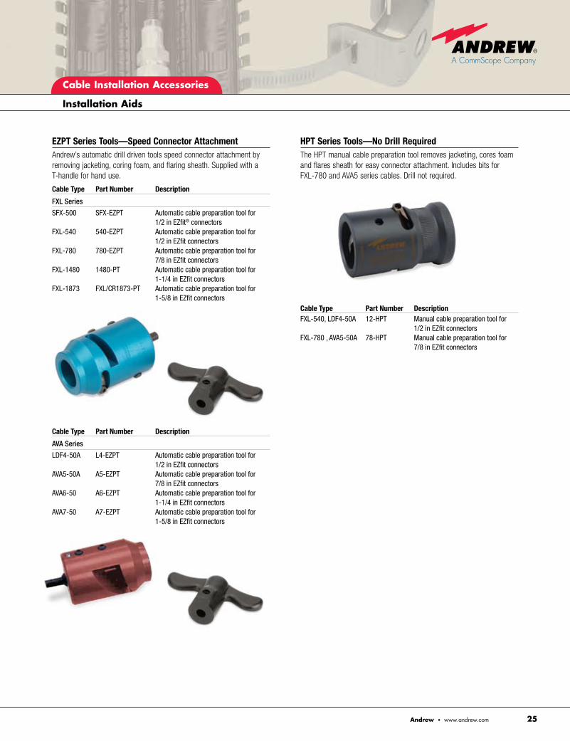
EZPT Series Tools—Speed Connector AttachmentAndrew’s automatic drill driven tools speed connector attachment by removing jacketing, coring foam, and flaring sheath. Supplied with a T-handle for hand use.
Cable Type Part Number Description
FXL Series
SFX-500 SFX-EZPT Automatic cable preparation tool for 1/2 in EZfit® connectors
FXL-540 540-EZPT Automatic cable preparation tool for 1/2 in EZfit connectors
FXL-780 780-EZPT Automatic cable preparation tool for 7/8 in EZfit connectors
FXL-1480 1480-PT Automatic cable preparation tool for 1-1/4 in EZfit connectors
FXL-1873 FXL/CR1873-PT Automatic cable preparation tool for 1-5/8 in EZfit connectors
Cable Type Part Number Description
AVA Series
LDF4-50A L4-EZPT Automatic cable preparation tool for 1/2 in EZfit connectors
AVA5-50A A5-EZPT Automatic cable preparation tool for 7/8 in EZfit connectors
AVA6-50 A6-EZPT Automatic cable preparation tool for 1-1/4 in EZfit connectors
AVA7-50 A7-EZPT Automatic cable preparation tool for 1-5/8 in EZfit connectors
HPT Series Tools—No Drill RequiredThe HPT manual cable preparation tool removes jacketing, cores foam and flares sheath for easy connector attachment. Includes bits for FXL-780 and AVA5 series cables. Drill not required.
Cable Type Part Number Description FXL-540, LDF4-50A 12-HPT Manual cable preparation tool for
1/2 in EZfit connectorsFXL-780 , AVA5-50A 78-HPT Manual cable preparation tool for
7/8 in EZfit connectors

Cable Installation Accessories
Installation Aids
Andrew • www.andrew.com26
EZfit® Tool Replacement Blade KitsPart Number Description HPT-BK1278 Replacement blade kit for 1/2 in and 7/8 in HPT toolsEZPT -BKU12 Replacement jacket removal blade kit for L4 EZPT toolsEZPT-BKUA5 Replacement jacket removal blade kit for A5 EZPT toolsEZPT-BKUA6 Replacement jacket removal blade kit for A6 EZPT toolsEZPT-BKUA7 Replacement jacket removal blade kit for A7 EZPT toolsEZPT -BKU540 Replacement jacket removal blade kit for 540-EZPT toolsEZPT-BKU780 Replacement jacket removal blade kit for 780-EZPT toolsEZPT-BKU1480 Replacement jacket removal blade kit for 1480-PT toolsEZPT-BKU1873 Replacement jacket removal blade kit for FXL/CR 1873-PT
Saw Guides for EZfit ConnectorsEZfit saw guides allow technicians to cut coaxial cable precisely at the crest of copper corrugations, at the exact distance required for attaching EZfit connectors.
Cable Type Part number Description LDF4-50A L4-SG Saw Guide for LDF4-50A EZfit connectorsAVA5-50A A5-SG Saw Guide for AVA5-50A EZfit connectorsAVA6-50 A6-SG Saw Guide for AVA6-50 EZfit connectorsAVA7-50 A7-SG Saw Guide for AVA7-50 EZfit connectors
EASIAX® Plus Automated Cable Preparation ToolFor Positive Stop Connectors
Cable installers and system designers can dramatically reduce cable preparation time and expense while improving overall system perfor-mance with the EASIAX Plus automated cable preparation tool. Fit the EASIAX Plus tool to any standard power drill, and it removes the cable jacket, outer conductor, and foam, then cuts back and chamfers the inner conductor to the correct dimensions for connector attach-ment—all in less than 15 seconds. The EASIAX Plus automated method of cable preparation means cable connections that are more consistent, more reliable, and more repeatable.
Tool Part Number Cable Type Connector TypeCPT-E2L2N LDF2-50 Type N connectors
CPT-E2L2DIN LDF2-50 7-16 DIN connectors
CPT-F4 FSJ4-50B FSJ4 version two connectors
CPT-L4ARC1 LDF4-50 7-16 DIN or Type N standard, RingFlare™, HL4RP-50 OnePiece™, or Positive Stop™ connectors
CPT-L45RC LDF4.5-50 RingFlare connectors
CPT-78U LDF5-50A 7-16 DIN or Type N standard, RingFlare, AVA5-50 OnePiece, or Positive Stop connectors VXL5-50 AL5-50
CPTL6 LDF6-50 7-16 DIN or Type N standard, RingFlare, OnePiece, or Positive Stop connectors
CPT-158U LDF7-50 7-16 DIN or Type N standard, RingFlare, AVA7-50 OnePiece, or Positive Stop connectors VXL7-50 AL7-50

Cable Installation Accessories
Installation Aids
27Andrew • www.andrew.com
Cable Types Cutting Tool Replacement Blades
Part Number Description Part Number, kit of 5 FSJ1, FSJ4, MCPT-1412 Cuts jacketing 209874 ETS1, and outer conductor RXL1* Series FSJ2, FSJ4, MCPT-3812 Cuts jacketing 209874 ETS2 Series and outer conductor LDF4, MCPT-L4 Cuts outer MCPT-BK4 HL4RP-50A, conductor and RXL4** Series scores jacketing LDF5, VXL5, MCPT-78 Cuts outer MCPT-BK5 AVA5, RXL5, conductor and AL5-50 Series inner conductor and scores jacketing * Except RXL1-1RNT ** Except RXL4-(1, 2 or 3) RNT
EASIAX® Cable Preparation ToolCuts precisely at crest of copper corrugation at the exact distance required for easy connector attachment. Clean cut makes flaring easier than ever. Precise blade depth makes it impossible to cut inner conductor.
EASIAX Replacement Blades
Tool Replacement Blade Kit
Part Number Part Number CPT-F4 CPT-BKCPT-L4ARC1 CPT-BKS1CPT-L45RC CPT-BKS1CPTL6 CPT-BK6CPT-158U CPT-BK7CPT-78U CPT-BK5
Recommended drill size for tools for 1/4 in through 1/2 in cables is 3/8 in torque value with 12 volt minimum. Cordless drill 14.4 minimum voltage, 400–650 RPM.
Recommended drill size for tools for 7/8 in through 1-5/8 in cable is 1/2 in. Cordless drill 15.4 minimum voltage, 400–650 RPM.
For detailed information on cable preparation, see Special Publication SP50262.
TIP!
TIP!

Cable Installation Accessories
Installation Aids
Andrew • www.andrew.com28
Connector Attachment Torque WrenchesPreset torque to match connector size
Andrew torque wrenches for EZfit® connectors are designed with a mechanism to audibly alert the installer that the proper torque has been set and then release the pressure.
Cable Type Part Number Description
EZfit Series Connectors
SFX-500 TW-SFX-EZFC Torque wrench for 3/8 in EZfit connectors
FXL-540, LDF4-50A TW-12-EZFC Torque wrench for 1/2 in EZfit connectors
FXL-780, AVA5-50A TW-78-EZFC Torque wrench for 7/8 in EZfit connectors
FXL-1480, AVA6-50 TW-114-EZFC Torque wrench for 1-1/4 in EZfit connectors
FXL-1873 AVA7-50 TW-158-EZFC Torque wrench for 1-5/8 in EZfit connectors
Other Connector Designs
LDF4-50A 247696 Torque wrench for 1/2 in OnePiece™ connectors
LDF4-50A 245154 Torque wrench for 1/2 in RingFlare™ connectors
Connector Coupling Nuts
All 244379 Torque wrench for Type N coupling nut
All 244377 Torque wrench for 7-16 DIN coupling nut
Grounding Lug Crimping ToolUsed to attach crimp-on lugs for standard and SureGround™ series. Not required for kits with factory-attached lugs.
Part Number207270
Combination and Open End WrenchesSpeed connector installation and improve performance with wrenches sized exactly per connector application. Each tool is made from high quality tool steel with black oxide finish.
Cable Size Part number Description3/8", 1/2", 7/8" EZW-7812 Combination wrench for SFX-500,
FXL-540, and FXL-780 EZfit connectors
3/8", 1/2", 7/8" CT-7812 Combination wrench for 1/2 in and 7/8 in Positive Stop™ connectors
7/8" 244459-5 1-1/4 in open end wrench for 7/8 in Positive Stop clamping nut
1-1/4" 1480-AW 45 mm open end wrench for 1-1/4 in EZfit connector clamping nut
1-1/4" 244459-6 1-7/8 in open end wrench for 1-1/4 in Positive Stop connector
1-5/8" 1873-AW 60 mm open end wrench for 1-5/8 in EZfit connector clamping nut
1-5/8" 244459-7 2-1/4 in open end wrench for 1-5/8 in Positive Stop connector
CT-7812EZW-8412
1873-AW

Cable Installation Accessories
Installation Aids
29Andrew • www.andrew.com
* Replacement blades for the SG series grounding kits may be used to retrofit GKT series tools. For example, blade kit number GBK-SG1278 may be installed to tool number GKT-78A to accommodate SG series grounding kits.
Single Turn Grounding Kit Prep ToolNow installers can prepare transmission line cable for grounding kit installation in one simple, precise step—and without using a knife! The Andrew aluminum grounding kit preparation tool takes just seconds to use: simply snap the tool in place around the cable and rotate. In one step the tool removes the exact amount of jacketing necessary to attach the grounding strap. The grounding kit preparation tool is a manually operated cutting device that quickly trims away a section of cable jacket for the purpose of grounding strap installation. The tool is ideal for use on cables mounted close to structures and other cable runs, and will not scrape or damage the cable’s outer conductor.
Multi Turn Jacket Stripping Tool For FXL Series Cables
The multi turn jacket stripping tool removes the bonded jacket in preparation for grounding kit attachment. The tool is constructed of an aluminum body with a heat-treated cutting blade for years of dependable use.
Grounding Kit Prep Tools and Replacement Blades
Cable Tool Replacement Grounding Type Number Blade Kit TypeFSJ4-50B GKT-F4A GKT-BKF4 StandardLDF4-50A GKT-L4A GKT-BK512 CSGL and SGL series GKT-L4SG GBK-SG1278* SG series7/8" corrugated GKT-78A GKT-BK512 CSGL and SGL series GKT-78SG GBK-SG1278* SG series1-1/4" corrugated GKT-114A GKT-BK67 CSGL and SGL series GKT-114SG GBK-SG114158* SG series1-5/8" corrugated GKT-158A GKT-BK67 CSGL and SGL series GKT-158SG GBK-SG114158* SG series
Cable Type Part Number DescriptionSFX-500 SFX-MSS Multi turn jacket stripping tool for SFX-500FXL-540 540-MSS Multi turn jacket stripping tool for FXL-540FXL-780 780-MSS Multi turn jacket stripping tool for FXL-780FXL-1480 1480-MSS Multi turn jacket stripping tool for FXL-1480FXL-1873 1873-AMSS Multi turn jacket stripping tool for FXL-1873
Jacket removal blade kit for SG series grounding kits
Manual cable preparation tool for 1/4 inch FSJ1-50A cableManual cable preparation tool for 1/2 inch LDF4-50A cable.Manual cable preparation tool for 7/8 inch corrugated cable.Combination wrench for 1/2 inch and 7/8 inch PositiveStop connectorsHeavy duty safety knifePrecision wire snips Plastic tipped hammer Straight hammer tips, plastic Tapered hammer tips, plastic Pin depth gauge—Type N male connectorPin depth gauge—Type N female connectorPin depth gauge—7-16 DIN male connectors Pin depth gauge—7-16 DIN female connectors Acid brush Emery cloth Tapered drift punch Connector pin straightening toolBrass soldering pliers Cut off guide—7/32 inchCut off guide—8/32 inchCut off guide—9/32 inchFlare tool—LDF4 cableFlare tool—LDF5 cableFlare tool—LDF5 cable
HELIAX® Hand Tool KitPart Number TB-COMP-KIT
The original collection of specialized hand tools remains available in this classic kit. Best suited for early generation connectors, contents include basic measuring, cutting and flaring tools as listed below.

Cable Installation Accessories
Installation Aids
Andrew • www.andrew.com30
Tool Selection GuideSelect the right tool for each cable size.
Cable Type Description
1/4 inch Coaxial Cable Tools
MCPT-1412 Manual cable preparation tool for 1/4 in FSJ1-50A cableCPT-L1 Automated cable preparation tool for LDF1-50 cable
3/8 inch Coaxial Cable Tools
SFX-EZPT Automated cable preparation tool for SFX-500 cableEZW-7812 Combination tool for 3/8 in through 7/8 in EZfit® connectorsTW-SFX-EZFC Torque wrench for 3/8 in EZfit connectors MCPT-3812 Manual cable preparation tool for FSJ2-50 cableSFX-MSS Jacket stripping tool for SFX-500 cable
1/2 inch Coaxial Cable Tools
540-EZPT EZfit Automated Cable Preparation Tool for FXL-540 cableL4-EZPT EZfit Automated Cable Preparation Tool for LDF4-50A cable12-HPT EZfit Manual Cable Preparation Tool for FXL-540 and
LDF4-50A cableEZPT-BKU540 Replacement jacket removal blade kit for 540-EZPT toolsEZPT-BKU12 Replacement jacket removal blade kit for L4-EZPT toolsHPT-BK1278 Replacement blade kit for 1/2 in and 7/8 in HPT toolsL4-SG Saw guide for LDF4-50A EZfit connectorsEZW-7812 Combination tool for 3/8 in through 7/8 in EZfit connectorsTW-12-EZFC Torque wrench for 1/2 in EZfit connectors CPT-F4 Automated cable preparation tool for FSJ4-50B cableCPT-L4ARC1 Automated cable preparation tool for LDF4-50A cableMCPT-L4 Manual cable preparation tool for 1/2 in LDF4-50A cableMCPT-1412 Manual cable preparation tool for 1/2 in FSJ4-50B cableCT-7812 Combination tool for 1/2 in and 7/8 in Positive Stop™ connectors241953 Chamfer tool for 1/2 in cableGKT-L4A Grounding kit preparation tool for LDF4-50A cable, SGL and
CSGL series grounding kitsGKT-BK512 Replacement blade kit for GKT-L4A tool, SGL and CSGL series
grounding kitsGKT-L4SG Grounding kit preparation tool for LDF4-50A cable, SG series
grounding kitsGBK-SG1278 Replacement blade kit for GKT-L4A and GKT-L4SG tools,
SG series grounding kits 540-MSS Jacket stripping tool for FXL-540 cable
7/8 inch Coaxial Cable Tools
780-EZPT EZfit Automated Cable Preparation Tool for FXL-780 cableA5-EZPT EZfit Automated Cable Preparation Tool for AVA5-50A cable78-HPT EZfit Manual Cable Preparation Tool for FXL-780 and AVA5-50EZPT-BKU780 Replacement jacket removal blade kit for 780-EZPT toolsEZPT-BKUA5 Replacement jacket removal blade kit for A5-EZPT toolsHPT-BK1278 Replacement blade kit for 1/2 in and 7/8 in HPT toolsA5-SG Saw guide for AVA5-50A EZfit connectorsEZW-7812 Combination tool for 3/8 in through 7/8 in EZfit connectorsCPT-78U Automated cable preparation tool for 7/8 in corrugated cable,
Postive Stop connectorsMCPT-78 Manual cable preparation tool for 7/8 in corrugated cable,
Positive Stop connectors
7/8 inch Coaxial Cable Tools (continued)
CT-7812 Combination tool for 1/2 in and 7/8 in Positive Stop connectors
244459-5 Open end wrench for 7/8 in Positive Stop connector, 1-1/4 in opening
TW-78-EZFC Torque wrench for 7/8 in EZfit connectors GKT-78A Grounding kit preparation tool for 7/8 in corrugated cable,
SGL and CSGL series grounding kitsGKT-BK512 Replacement blade kit for GKT-78A tool, SGL and CSGL
series grounding kitsGKT-78SG Grounding kit preparation tool for 7/8 in corrugated cable,
SG series grounding kitsGBK-SG1278 Replacement blade kit for GKT-78U and GKT-78SG tools,
SG series grounding kits 780-MSS Jacket stripping tool for FXL-780 cable
1-1/4 inch Coaxial Cable Tools
1480-PT EZfit Automated Cable Preparation Tool for FXL-1480 cableA6-EZPT EZfit Automated Cable Preparation Tool for AVA6-50 cableEZPT-BKU1480 Replacement jacket removal blade kit for 1480-PT toolsEZPT-BKUA6 Replacement jacket removal blade kit for A6-EZPT toolsA6-SG Saw guide for AVA6-50 EZfit connectors1480-AW Open end wrench for 1480 EZfit connectors, 1-3/4 in openingTW-114-EZFC Torque wrench for 1 1/4 in EZfit connectors CPTL6 Automated cable preparation tool for 1-1/4 in corrugated cable244459-6 1-7/8 in open end wrench for 1-1/4 in Positive Stop connector GKT-114A Grounding kit preparation tool for 1-1/4 in corrugated cable,
SGL and CSGL series grounding kitsGKT-BK67 Replacement blade kit for GKT-114A tool, SGL and CSGL
series grounding kitsGKT-114SG Grounding kit preparation tool for 1-1/4 in corrugated cable,
SG series grounding kitsGBK-SG114158 Replacement blade kit for GKT-114U and GKT-114SG tools,
SG series grounding kits1480-MSS Jacket stripping tool for FXL-1480 cable
1-5/8 inch Coaxial Cable Tools
FXL/CR1873-PT EZfit Automated Cable Preparation Tool for FXL-1873 coaxial cable
A7-EZPT EZfit Automated Cable Preparation Tool for AVA7-50 coaxial cable
EZPT-BKU1873 Replacement jacket removal blade kit for FXL/CR1873-PT toolEZPT-BKUA7 Replacement jacket removal blade kit for A7-EZPT toolsA7-SG Saw guide for AVA7-50 EZfit connectors1873-AW Open end wrench for 1873 EZfit connectors, 2-3/8 in openingTW-158-EZFC Torque wrench for 1-5/8 in EZfit connectorsCPT-158U Automated cable preparation tool for 1-5/8 in corrugated
cable, Positive Stop connectors244459-7 Open end wrench for 1-5/8 in Positive Stop connector,
2-1/4 in opening GKT-158A Grounding kit preparation tool for 1-5/8 in corrugated cableGKT-BK67 Replacement blade kit for GKT-158A tool, SGL and CSGL
series grounding kitsGKT-158SG Grounding kit preparation tool for 1-5/8 in corrugated cable,
SG series grounding kitsGBK-SG114158 Replacement blade kit for GKT-158U and GKT-158SG tools,
SG series grounding kits 1873-AMSS Jacket stripping tool for FXL-1873 cable

LIGH
TNIN
G PRO
TECTIO
N
( Grounding Kits
( Grounding Bars
( Surge Arrestors

Lightning Protection
Grounding Kits
Andrew • www.andrew.com32
Grounding Point 1
Grounding Point 4(Runs longer than 200 ft)
Grounding Point 2
Grounding Point 3
Transmission Line GroundingA well designed system uses grounding kits to provide a bond between the cable and the tower/earth ground system. One grounding kit is recommended at tower top, tower bottom, at 200 ft (60 m) intervals (where applicable), and at the entrance to the equipment shelter. Andrew solid copper grounding kits have passed United States Air Force light-ning simulation tests and meet MIL-STD-188-124A. The non-braided solid copper construction of all Andrew grounding kits eliminates corro-sion caused by moisture retention and “wicking.” A heat shrink tube protects the cable terminal connection.
( Compact SureGround™ ( SureGround™ ( Standard
Grounding Kit SelectionSeveral grounding kit options are available to meet the requirements of any transmission line grounding application.
d Compact SureGround™ grounding kits provide the fastest, easiest installation with the highest degree of lightning protection. Their self-sealing design clips and locks onto the cable in less than a minute.
d SureGround grounding kits, an industry favorite, offer clip on attach-ment with taped weatherproofing.
d Standard grounding kits provide the best grounding solution for elliptical waveguide. The copper grounding strap is coiled around the cable and weatherproofed with tape.
d Universal grounding kits can be applied to a broad range of coaxial or elliptical transmission lines.
Grounding Kit Selection Guide
Compact SureGround SureGround Standard UniversalKey Feature Over-molded weatherproof Preformed clip-on strap Wraparound grounding strap Multiple cable size design for easy, fast installation wraparound grounding strapBenefits Uniform installation compact Requires no tools Fits standard coaxial cable Breakaway design fits design for bundled installation for installation and elliptical waveguide multiple sizes of coaxial cable and elliptical waveguideInstallation Time Less than 1 minute About 3 minutes About 6 minutes About 7 minutesConstruction Preformed copper Pre-tensioned copper Copper grounding strap Copper grounding strap grounding strap grounding clip Over-molded weatherproof Standard weatherproofing Standard weatherproofing Standard weatherproofing boot, locking bail
Heavy Duty Ground Lead
Andrew grounding kits use heavy duty 6 gauge ground leads to maximize performance. The MIL-STD-188-124B compliant copper ground lead reduces dc resistance. The extremely pliable jacket provides protection and makes it easy to maneuver the lead into position for attachment to the down conductor.
d Solid copper construction for high current handling capability, compatibility with copper cable outer conductors
d Meets military standards at commercial prices.
d Provides certainty of continued operation, tested at an independent laboratory

Lightning Protection
Grounding Kits
33Andrew • www.andrew.com
Compact SureGround™ Grounding KitsNow wireless communications system installers and designers can protect their systems from the effects of lightning easier and at lower cost. The new Compact SureGround grounding kit, available only from Andrew, is a one-piece grounding assembly with the weatherproofing molded right into the grounding strap.
Compact SureGround grounding kit features:
Easy attachment
d Self-locking, self-sealing weatherproof enclosure eliminates loose hardware and taping
d Saves up to an hour of installation time per typical nine run site
Sure protection
d Largest surface contact area in the industry
d Provides surety of protection against even the most severe lightning strikes
d Waterproof to IEC529, IP68
Compact size
d “Clip and lock” installation ideal for tight cable bundles or crowded towers
d Exclusive universal grounding lug can be fitted to a one- or two-hole earthing attachment point.
United States Patent: 6,548,762. Other patents pending.
More Information
d See Compact SureGround ordering information on page 35
d See the installation video at http://awapps.commscope.com/video/default.aspx
Position Compact SureGround grounding kit
Clip and lock to seal
Universal SureGround™ Grounding KitsFast Installation, Complete Protection
Protect your equipment from the effects of lightning with SureGround Grounding Kits.
The SureGround clips in place and provides protection against lightning strikes in excess of 100 kA. The grounding kits are constructed with a tin-plated solid copper clip that ensures a low resistance, corrosion resistant connection to copper or aluminum coaxial cable. An insulated six-gauge stranded copper conductor with universal 1–2 hole attach-ment lug provides connection to the grounding system. Simply clip the SureGround onto your cable for fast, reliable, MIL spec compliant light-ning protection.
SureGround Grounding Kits are compatible with smoothwall and corru-gated coaxial cables with aluminum or copper outer conductors. Each kit includes a butyl tape weatherproofing system and stainless steel attachment hardware.
d Fits smoothwall and corrugated cabled Compatible with aluminum and copper outer conductorsd Fast clip-on installationd MIL-STD-188-124B compliant
The Compact SureGround Kit with integrated weatherproofing is the choice for the speediest installation, best fit in tight locations, and long-term protection.
TIP!
TIP!
Completed
Easy Installation

Lightning Protection
Grounding Kits
Andrew • www.andrew.com34
Connector Grounding Kit for Mounting RailPart Number DescriptionCGT12 Connector grounding kit fits all F4 and L4 (except OnePiece™)
series connectorsCGT58 Connector grounding kit fits all L4.5 and L5
standard connectorsCGT78 Connector grounding kit fits all L5, V5, A5, OnePiece,
and Positive Stop™ series connectorsCGT114 Connector grounding kit fits all L6 series connectorsCGT158 Connector grounding kit fits all L7 and V7
series connectorsCGT214 Connector grounding kit fits all L12 series connectors
40 mm x 22 mm x 17 mm
Universal Grounding LugsThis grounding lug provides you with the option of a one-hole configuration or two-hole configuration. Just break away the bottom portion of the lug and this will give you your one-hole lug. This universal lug will fit common buss bar configurations with two-hole spacings of 0.750, 0.815, or 1.0 in. Designed to crimp on 6 gauge or 16 mm2 grounding wire. Included on all grounding kits and available separately.
Part Number Description 245529-10 Universal grounding lug, kit of 10 207136-3 Grounding lug hardware kit
Standard Grounding KitsEasy Installation for System Protection
Standard grounding kits are intended for elliptical waveguide installations. One grounding kit is recommended at the tower top, tower bottom, at 200 ft (60 m) intervals, and at the entrance to the equipment shelter. Standard grounding kits (204989 and 241088 series) require few steps to install and include easy-to-follow instructions. Proper tensioning is ensured by an expansion section that provides visual indication that the strap is secured.
Series 204989 and 241088 kits include a solid copper strap riveted to the grounding wire, coiling tool for proper tightening, universal grounding lug, tower attachment hardware, and a two-part tape weath-erproofing system. Field-attachable, crimp-on grounding lugs require a crimping tool (not included).
For two bolt grounding
Snap off pre-scored lug for one hole option
For one bolt grounding
Crimping Tool for SureGround™ and Standard Grounding The crimping tool is used to attach crimp-on lugs for standard and SureGround series grounding kits. Not required for kits with factory attached lugs.
Part Number Description 207270 Crimping tool, quantity 1Universal Grounding Kit
Part Number DescriptionUG12158-15B4 1/2 in–1-5/8 in EW180–EW63 60 in field attached lug

Lightning Protection
Grounding Kits
35Andrew • www.andrew.com
Compact SureGround™
Size/Type Part Number Description
1/2" LDF4 CSGL4-15B4 Compact SureGround™ Grounding Kit for 1/2 in corrugated coaxial cable, 1.5 m (5 ft) lead, unattached lug7/8" CSGL5-15B4-T Compact SureGround™ Grounding Kit for 7/8 in corrugated coaxial cable, 1.5 m (5 ft) lead, unattached lug1-1/4" CSGL6-15B4 Compact SureGround™ Grounding Kit for 1-1/4 in corrugated coaxial cable, 1.5 m (5 ft) lead, unattached lug1-5/8" CSGL7-15B4-T Compact SureGround™ Grounding Kit for 1-5/8 in corrugated coaxial cable, 1.5 m (5 ft) lead, unattached lug SureGround™
Size/Type Part Number Description
1/2 " SG12-12B2U SureGround Grounding Kit for 1/2 in coaxial cable, 1.2 m (4 ft) lead, unattached lug5/8 " SG58-12B2U SureGround Grounding Kit for 5/8 in coaxial cable, 1.2 m (4 ft) lead, unattached lug7/8 " SG78-12B2U SureGround Grounding Kit for 7/8 in coaxial cable, 1.2 m (4 ft) lead, unattached lug1-1/4 " SG114-12B2U SureGround Grounding Kit for 1-1/4 in coaxial cable, 1.2 m (4 ft) lead, unattached lug1-5/8 " SG158-12B2U SureGround Grounding Kit for 1-5/8 in coaxial cable, 1.2 m (4 ft) lead, unattached lug2-1/4 " SG214-12B2U SureGround Grounding Kit for 2-1/4 in coaxial cable, 1.2 m (4 ft) lead, unattached lug Standard Grounding Kit
Size/Type Part Number Description
1/4" and 3/8", EW240, EW380 223158-4 Standard Grounding Kit for 1/4 in and 3/8 in corrugated coaxial cable and elliptical waveguide 240 and 380, 1.5 m (5 ft) lead, unattached lug
EW180, EW220 241545 Standard Grounding Kit for 1/2 in corrugated coaxial cable and elliptical waveguide 180 and 220, 1.5 m (5 ft) lead, unattached lug
EW85, EW90, EW127A, EW132 220497 Standard Grounding Kit for 5/8 in and 7/8 in corrugated coaxial cable and elliptical waveguide 85, 90, 127A, and 132, 1.5 m (5 ft) lead, unattached lug
EW64, EW77 241088-60 Standard Grounding Kit for 1-1/4 in corrugated coaxial cable and elliptical waveguide 64 and 77, 1.5 m (5 ft) lead, unattached lug
EW52, EW63 220498 Standard Grounding Kit for 1-5/8 in corrugated coaxial cable and elliptical waveguide 52 and 63, 1.5 m (5 ft) lead, unattached lug
EW43 204989-28 Standard Grounding Kit for elliptical waveguide 43, 1.5 m (5 ft) lead, unattached lug3", EW28, EW37 223700-724 Standard Grounding Kit for 2-1/4 in and 3 in corrugated coaxial cable and elliptical
waveguide 28 and 37, 1.5 m (5 ft) lead, unattached lug Universal Grounding Kit
Size/Type Part Number Description
1/4"–5/8" coaxial cable and elliptical waveguide GK-SUNV Universal Grounding Kit for 1/4 in through 5/8 in corrugated coaxial cable
Universal Connector Grounding Kit
Size/Type Part Number Description
1/2"–1-5/8" 244495 Universal connector grounding kit

Lightning Protection
Grounding Bars
Andrew • www.andrew.com36
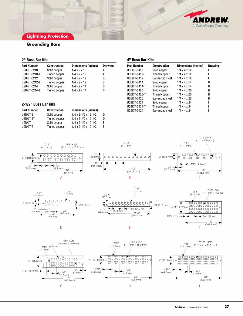
Universal Grounding Buss BarsAndrew offers a complete range of grounding buss bar sizes and hole pattern configurations to accommodate just about any application. Each grounding bar is made from 1/4 inch solid copper bar stock and is avail-able with optional tin plating. New theft deterent features include stamped identification (see photo), versions made from 1/4 inch galvanized steel and optional theft proof hardware. Kits come complete with insulators, stainless steel brackets, adapters, and hardware for mounting to a wall or tower.
UGBKIT-0420
UGBKIT-0420-T
GGBKIT-0420
TRH-38 Tamper Resistant Hardware
Lightning Protection
Grounding Bars
37Andrew • www.andrew.com
13/16"(20.6 mm)
7/16"(11.1 mm)
1-1/4" (31.8 mm)
1-3/8" (34.9 mm)
12-1/2" (317.5 mm)
1" (25.4 mm)
1" (25.4 mm)
2-1/2" (63.5 mm)
7/16"(11.1 mm)
13/16"(20.6 mm)
2-1/2"(63.5 mm) 1" (25.4 mm)
1-3/8" (34.9 mm)
19-1/2"(495.3 mm)
1-1/4" (31.8 mm)
7/16"(11.1 mm)
12"(304.8 mm)
4" (101.6 mm)
1/2" (12.7 mm) 3/4" (19 mm)
7/16" x 5/8"(11.1 mm x 15.9 mm)
(11.1 mm)
(355.6 mm)
(12.7 mm)(12.7 mm)
4" (101.6 mm)
1-1/2" (38.1 mm)
(6.4 mm)(11.1 mm x 15.9 mm)
7/16" x 5/8"(11.1 mm x 15.9 mm)7/16"
(11.1 mm)
4" (101.6 mm)
20"(508 mm)
3/4"(19 mm)
1-3/4"(44.5 mm)
2" Buss Bar Kits Part Number Construction Dimensions (inches) DrawingUGBKIT-0210 Solid copper 1/4 x 2 x 10 AUGBKIT-0210-T Tinned copper 1/4 x 2 x 10 AUGBKIT-0212 Solid copper 1/4 x 2 x 12 BUGBKIT-0212-T Tinned copper 1/4 x 2 x 12 BUGBKIT-0214 Solid copper 1/4 x 2 x 14 CUGBKIT-0214-T Tinned copper 1/4 x 2 x 14 C
2-1/2" Buss Bar Kits Part Number Construction Dimensions (inches)UGBKIT-2 Solid copper 1/4 x 2-1/2 x 12-1/2 DUGBKIT-2T Tinned copper 1/4 x 2-1/2 x 12-1/2 DUGBKIT Solid copper 1/4 x 2-1/2 x 19-1/2 EUGBKIT-T Tinned copper 1/4 x 2-1/2 x 19-1/2 E
4" Buss Bar Kits Part Number Construction Dimensions (inches) DrawingUGBKIT-0412 Solid copper 1/4 x 4 x 12 FUGBKIT-0412-T Tinned copper 1/4 x 4 x 12 FGGBKIT-0412 Galvanized steel 1/4 x 4 x 12 FUGBKIT-0414 Solid copper 1/4 x 4 x 14 GUGBKIT-0414-T Tinned copper 1/4 x 4 x 14 GUGBKIT-0420 Solid copper 1/4 x 4 x 20 HUGBKIT-0420-T Tinned copper 1/4 x 4 x 20 HGGBKIT-0420 Galvanized steel 1/4 x 4 x 20 HUGBKIT-0424 Solid copper 1/4 x 4 x 24 IUGBKIT-0424-T Tinned copper 1/4 x 4 x 24 IGGBKIT-0424 Galvanized steel 1/4 x 4 x 24 I
7/16" x 5/8"(11.1 mm x 15.9 mm)
7/16"(11.1 mm)
2" (50.8 mm)
1/2"(12.7 mm)
3/4"(19.1 mm) 10"
(254 mm)
7/16"(11.1 mm)
12"(304.8 mm)
2"(50.8 mm)
1/2"(12.7 mm)
7/16"(11.1 mm)
1/2"(12.7 mm)
2" (50.8 mm)
14"(355.6 mm)
3/4" (19.1 mm)
7/16" x 5/8"(11.1 x 15.9 mm)
7/16" x 5/8"(11.1 mm x 15.9 mm)7/16"
(11.1 mm)
4" (101.6 mm)
20"(508 mm)
3/4"(19 mm)
1-3/4"(44.5 mm)
G
D
A
H
E
B
I
F
C

Lightning Protection
Grounding Bars
Andrew • www.andrew.com38
Universal Arrestor Ground Bar AssemblyThis pre-punched solid copper ground bar assembly simplifies mounting and grounding of surge arrestors inside the building. Instead of relying on individual wires or field-fabricated trapeze setups, the Andrew universal arrestor ground bar assembly provides a uniform mounting and grounding point for surge arrestors and grounding leads. The 1/8 inch assembly uses three horizontal members that can be oriented flat or upright and adjusted vertically as needed to accommodate various surge arrestor types. Also included is a mounting kit that includes ceiling brackets, insulators, threaded rod, and hardware.
d Compatible with standard entry port sizes
d Height-adjustable bars
d Solid copper construction
d Accepts bulkhead or bolt grounded surge arrestors
d Accommodates one- and two-hole grounding lugs
d Eliminates need for internal buss bar
Part Number DescriptionUGBA-DIN-36 Three 6-position ground bars punched for oversized
7-16 DIN mount arrestors (APTL and APT series) or bolt-grounded arrestors
UGBA-36 Three 6-position ground bars punched for most 7-16 DIN, Type N or bolt-grounded arrestors (Andrew APG and APM series arrestors)
UGBA-DIN-34 Three 4-position ground bars punched for oversized 7-16 DIN mount arrestors (APTL and APT series) or bolt-grounded arrestors
UGBA-34 Three 4-position ground bars punched for most 7-16 DIN, Type N, or bolt-grounded arrestors (Andrew APG and APM series arrestors)

Lightning Protection
Surge Arrestors
39Andrew • www.andrew.com
T-SeriesDual Band
dc PassDual Band
Replaceable Gas Tube
dc BlockIntegrated Bias Tee
T-Series Surge Arrestors Arrestor Plus® T-series surge arrestors give engineers more flexibility when configuring lightning protection systems. This slim profile arrestor fits easily inside equipment enclosures, is bi-directional, and offers true multistrike protection. The arrestor plus bulkhead mount T-series features universal Type N and 7-16 DIN interfaces. The dc passing version allows current to travel to the top of the tower.
Arrestor Plus® Lightning Surge Arrestors Add the final measure of protection to your equipment from lightning current traveling down the transmission line with Arrestor Plus surge arrestors. All designs are completely weatherproof and feature low return, insertion loss, and low intermodulation. Our wide range of surge arrestor types and configurations support most applications.
Replaceable Gas Tube Surge ArrestorsOffering broadband performance from 0–2200 MHz and excellent elec-trical characteristics, Arrestor Plus replaceable gas tube surge arrestors are easy to install, are bidirectional, and feature dc pass capability through the center conductor to the active tower top electronics. The unit’s removable cap makes periodic maintenance fast and easy.
45–2200 MHz, 90 VAPG-BDFDF-090APG-BDFDM-090APG-BNFNF-090APG-BNFNM-090
45–2200 MHz, 350 VAPG-BDFDF-350APG-BDFDM-350APG-BNFNF-350APG-BNFNM-350
824–960 MHz and 1710–2170 MHz
APT-DFDF-DBAPT-DFDM-DBAPT-BDFDF-DBAPC-BDFDM-DBAPT-BDFDM-DBAPT-NFNF-DBAPT-NFNM-DBAPT-BNFNF-DBAPT-BNFNM-DB
824–960 MHz and 1710–2170 MHz dc Passing
APTDC-BDFDF-DBAPTDC-BDFDM-DBAPTDC-BNFNM-DB
380–520 MHz
APC-BDFDM-450A
675–825 MHz
APC-BDFDM-700A
2000–2800 MHz
APB-BNFNF-2400 APB-BNFNM-2400

Bias Tee Andrew bias tees are designed to protect equipment from damaging transients induced by lightning strikes. This product allows the injec-tion of dc current to the center conductor of the feeder line, allowing current to travel to the top of the tower. Bias tees are unidirectional devices. Ports are clearly marked to show mounting direction with either “Antenna” or “Radio”.
824–960 MHz and 1710–2170 MHz Photo ReferenceABT-DFDM-ADBH AABT-DFDM-DB BABT-DMDF-ADBH AABT-DMDF-DB BABT-NFNM-DB BABT-NMNF-DB BABT-DFDM-ADBA AISG Compliant AABT-DMDF-ADBA AISG Compliant A
dc BlockThe dc block is designed to block dc signals from passing through the center conductor of a coaxial transmission line. The dc block is a bidi-rectional RF device. Either RF port may be connected to the equipment side or the antenna side of the transmission line interface to provide equivalent protection.
824–960 MHz and 1710–2170 MHzADCB-DFDM-DB
Integrated Surge Arrestor/ConnectorThe Arrestor Plus® integrated, T-series lightning surge arrestor is a one-piece surge arrestor/HELIAX® connector. It uniquely combines the reliability of quarterwave shorting stub technology with the proven performance of HELIAX connectors to deliver premium lightning protec-tion in a single component.
824–960 MHz and 1710–2170 MHzAPTA5DC-BDF-DBAPTA7DC-BDF-DB
Surge Arrestor AccessoriesPart Number DescriptionGASTUBE-090 90 volt gas tube replacement, kit of 10GASTUBE-350 350 volt gas tube replacement, kit of 10243951 90 degree mounting/grounding bracket, Type N243950 90 degree mounting/grounding bracket, 7–16 DIN244847 Integrated surge arrestor/connector 90 degree
mounting/grounding bracket, 7–16 DINDF-CAPKIT Plated port sealing cap, 7–16 DIN (Fits onto DIN female
connector), IP 66 and 68DM-CAPKIT Plated port sealing cap, 7-16 DIN (Fits onto 7-16 DIN
male connector), IP 66 and 68.
Lightning Protection
Surge Arrestors
Andrew • www.andrew.com40
A. Bias Tee Standard Body SMA Port
B. Bias Tee Compact Cylindrical Body SMA Port

APPEN
DIXES

Appendix 1
Quarterwave Stub Surge Arrestors
Andrew • www.andrew.com42
Quarterwave Stub Surge Arrestors—Considerations and SelectionQuarterwave Stub (QWS) Surge Arrestor Technology
An understanding of the key concepts of quarterwave stub tech-nology and its relationship to lightning transients can be of great benefit to transmission line system designers and operators. With this understanding, system designers and operators can more fully utilize lightning protection systems that use QWS technology as well as understand the critical role multistrike ability plays in light-ning protection systems.
Arrestor Plus® T-series surge arrestors from Andrew Corporation employ QWS technology, a unique design that allows microwave signals to pass unattenuated while shunting the lower frequencies associated with lightning-induced transients to ground. This proven QWS technology is utilized in APT Arrestor Plus® Surge Arrestors.
To understand QWS technology, one needs to understand lightning. The lightning transient is characterized by a current waveform with an 8-microsecond rise time (time to reach 90% of the peak value) and a 20-microsecond decay time (time to decay to 50% of the peak value). Peak currents can reach excessive values, but 50% of all strikes will reach values of only 18 kA. It is important to remember that this is only a laboratory characterization of the lightning transient, but it facilitates standardized testing techniques for the industry. Figure 1 depicts an actual laboratory-generated 8/20 µsec waveform that was used to evaluate Andrew surge arrestors. For more detailed information regarding laboratory generated surge waveforms, see IEC 60-2, ANSI-IEEE Std 4-1978, and ANSI C62.1-1984.
The substantial energy associated with lightning transients has frequency components near dc with components of decreasing value of energy extending through 160 kHz.
The effectiveness of surge arrestors is characterized by the throughput energy and the ability to withstand multiple surges. These characteristics are readily measurable in a laboratory equipped with the appropriate test equipment. Throughput energy is a measure of the amount of energy passed through the output of the device when the input of the device is subjected to a light-ning transient waveform. The throughput energy can be calculated from the residual voltage waveform using the relationship:
Figure 2 shows the residual output voltage present when an APT Series Surge Arrestor was subjected to an actual 8/20 µsec waveform with a peak current of 20 kA. In this case, the residual voltage was recorded across a 50 ohm load. The resulting throughput energy was 72 microjoules. The objective of the surge arrestor is to minimize the throughput energy to a manageable level. Most microwave transmitters and receivers used in today’s wireless systems are capable of withstanding throughput energy levels of 10 millijoules or less.
The ability to withstand multiple strikes is also an important measure of surge arrestor merit. Multistrike ability is measured by subjecting the QWS surge arrestors to repeated surges and observing if the arrestors continue to properly function or show
Time (microseconds)Figure 1
Time (microseconds)Figure 2
Laboratory generated 8 x 20 µsec lightning surge current waveform.Peak current: 21 kiloamperes
Residual output voltage of an APT quarterwave stub surge arrestor when subjected to an 8 x 20 µsec current surge with peak current of 20,000 amperes.

Appendix 1
Quarterwave Stub Surge Arrestors
43Andrew • www.andrew.com
signs of degradation. No evidence of failure or degradation was observed after subjecting the Andrew Arrestor Plus® surge arres-tors to over 100 strikes at 50 kA peak current using an 8/20 µsec waveform. This level of reliability is essential in protecting today’s telecommunications systems from the potential of damaging light-ning transients.
Arrestor Plus QWS surge arrestors are carefully designed and tested to provide a low impedance path to ground for any lightning induced transient energy present on the center conductor of the transmission line. These surge arrestors are designed to withstand multiple strikes of the most severe surges. The unique attributes of QWS surge arrestors are made possible by careful design and selection of the geometry and cross-sectional area of the conductors that make up the shorting stub. QWS designs result in extremely low throughput energy devices with true multistrike ability.
When selecting a surge arrestor, the RF performance must be considered. Characteristics that describe RF performance are operating bandwidth, VSWR (return loss), insertion loss, maximum average power, and passive intermodulation distortion.
The operating bandwidth of quarterwave shorted stubs is limited, but Andrew Arrestor Plus QWS surge arrestors are designed to accommodate the operating bandwidth requirements of today’s wireless telecommunications systems. Quarterwave shorted stubs can be designed to accommodate up to 20% bandwidth. The bandwidth characteristics of the surge arrestors is similar to that of a bandpass filter: RF signals at the center of the band pass unat-tenuated, while out-of-band signals (such as lightning transients) are diverted harmlessly to ground.
Figure 3 shows the measured wideband S11 (return loss) of a QWS surge arrestor. Note that in the band of interest, the S11 levels are typically -30 dB.
It is key to note that dc signals cannot be passed through the device. When dc passing is required, as is often the case for tower top active electronics, then it is strongly recommended to use Andrew APG gas tube series surge arrestors. For more information on APG gas tube series arrestors, see Appendix 2.
The lowest center frequency of operation is limited to approxi-mately 400 MHz, while the highest center frequency is limited by the cutoff frequency of the coaxial cable being used. Figure 4 shows a cross-sectional view of a QWS surge arrestor. The lower operating frequency is limited due to the physical size of the shorting stub. When the shorting stub reaches too long of a physical length, the stub appears as an inductive load, resulting in excessive residual voltages. Quarterwave shorted stubs can be designed to accommodate systems operating as high as 12 GHz.
Frequency (MHz)Figure 3
Figure 4
S11 vs Frequency for a QWS surge arrestor
In the operating bandwidth of the Arrestor Plus® QWS surge arrestors, the RF performance characteristics are optimal. At the operating frequencies of the Arrestor Plus, the insertion loss is less than 0.1 dB, no more than adding a connector to the transmission line path. Figure 5 shows the measured S21 (insertion loss) perfor-mance of an APM type QWS surge arrestor. Note that in the band of interest, the S21 levels are better than -0.05 dB.
The maximum average operating power of the Arrestor Plus QWS surge arrestor is limited by the connector interface. The suggested maximum average operating power for Type N connectors is 600 watts at 900 MHz. The suggested maximum average operating power for 7-16 DIN connectors is 3000 watts at 900 MHz. Exceeding these values can result in excessive temperature rise and permanent damage to the device.
Intermodulation distortion (IMD) is a major concern in today’s PCS, cellular, ESMR, and other wireless systems. IMD is caused by nonlinear effects within a device. For connectors, these nonlinear effects can be caused by poor contact between internal surfaces, plating with ferrous materials, such as nickel, or by oxide build up between contact surfaces.

Appendix 1
Quarterwave Stub Surge Arrestors
Andrew • www.andrew.com44
Arrestor Plus® surge arrestors are designed with high pressure contacts, premium platings, and are compensated to offer the best possible IMD performance.
The functionality of Arrestor Plus QWS surge arrestors can be readily evaluated by using ordinary RF field test equipment. If there is no degradation of the VSWR or insertion loss of the arrestor, then the surge arrestor is reassuringly functioning as a transient lightning protection device. VSWR and insertion loss measurements can be made by using vector or scalar network analyzers as well as a variety of other readily available field test equipment. No other maintenance is required. As obvious as it may seem, surge arres-tors should never be installed or tested when a storm is occurring or approaching.
System requirements often dictate outdoor installation of surge arrestors. Arrestor Plus surge arrestors are ideal for these applica-tions and designed to withstand the harshest environments and are extensively tested to meet industry standard specifications for waterproofing, vibration, thermal cycling, mechanical shock, salt spray, fungus, and moisture resistance.
QWS surge arrestors are excellent choices for wireless base station applications where superior RF performance is required to ensure call quality and when protection against multiple lightning strikes is of primary importance.
Frequency (MHz)Figure 5
S21 vs Frequency for a QWS surge arrestor

Appendix 2
Gas Tube Surge Arrestors
45Andrew • www.andrew.com
Using the Maximum Average Power Derating Curves GSM Radio Operating Conditions:
1. Number of carriers = 22. Power of each carrier (dBm) = +42 dBm carriers at the output
of a hybrid combiner (+45 dBm at combiner input)3. VSWR = 1.25:14. dc Bias = 15 V5. Nominal Impedance = 50 Ω
Gas Tube Surge Arrestors—Considerations and SelectionGas Tube Surge Arrestor Technology To simplify selecting the appropriate gas tube surge arrestor for your system plots, maximum average power vs. VSWR have been compiled. Figures 1 and 2 show plots of maximum average power vs. VSWR for 90 and 350 volt gas tubes. Each graph shows different values of commonly used dc bias voltages. These graphs were established from extensive laboratory testing and include the appropriate safety factors to ensure proper gas tube selection. Using these graphs for selecting a gas tube will optimize the level of protection required for your system.
Gas tube elements are offered in various spark-over voltages. Andrew Corporation simplifies the selection process by limiting the choice to two options, 90 volt for GPS applications and 350 volt for many other wireless applications requiring a dc bias. Plots of maximum average power vs. VSWR have been compiled for the 90 and 350 volt gas tubes from extensive laboratory testing and have built-in safety factors to ensure proper selection. See figures 3 and 4. Each graph shows several different values of commonly used dc bias voltages. Using these graphs for selecting a gas tube will optimize the level of protection required for your system.
When working in today’s environment of diplexed signals, overlaid networks, tower mounted amplifiers, and multiple carriers, it is necessary to verify that a system’s maximum average power does not exceed that rating for the gas tube. The following example illus-trates the process of using the voltage derating curves that follow.
1. Calculate the peak instantaneous voltage of a single +42 dBm carrier for a 50 ohm based system
Average Power 10 (average power per carrier in dBm/10) per Carrier (watts)= 1000 V rms per carrier (volts): = √ average power per carrier (watts) • Impedance (ohms)
V rms per carrier (volts) = 28.284
Vpeakpercarrier(volts):=√2• V rms per carrier (volts)
V peak per carrier (volts) = 40
Therefore, the peak instantaneous voltage of a single +42 dBm carrier is 40 volts.
2. Calculate the peak instantaneous voltage of a two, +42 dBm carrier, 50 ohm based system
Peak instantaneous voltage (volts):= V peak per carrier (volts) • number of carriers (N)
Peak instantaneous voltage (volts) = 80
Therefore, the peak instantaneous voltage of a two +42 dBm carriers is 80 volts.
3. Calculate the peak instantaneous power of two, +42 dBm carrier, 50 ohm based system
Peak instantaneous power (watts):= (Peak instantaneous voltage (volts))2
Impedance (ohms)
Peak instantaneous power (watts) = 128
Peak instantaneous power (dBm):=
10 • log Peak instantaneous power (watts)
0.001
Peak instantaneous power (dBm) = 51.072
Therefore, the peak instantaneous voltage of two, +42 dBm carriers is 128 watts (+51 dBm).
4. The gas tube selection curves are specified as Maximum Average Power vs. VSWR. Therefore, it is required to calculate an estimate of the average (RMS) power from the peak instantaneous power. A reasonable calculation of this estimate is shown below:
Peak instantaneous voltage (volts) = 80
RMS equivalent (volts): = Peak instantaneous voltage (volts) √2
RMS equivalent (volts) = 56.569
RMS equal power (watts):= (RMS equivalent (volts))2
Impedance (ohms)
RMS equal power (watts) = 64
Therefore, to utilize the gas tube selection curves, an approximate value of 64 watts average power would provide a reasonable estimate.
Note that for this calculation, the dc bias voltage was not specified and the VSWR was not specified. The gas tube selection curves provide a derating for both the VSWR and dc bias voltage.
5. Apply calculated information to the derating curves.

Appendix 2
Gas Tube Surge Arrestors
Andrew • www.andrew.com46
1.25
Vdc bias 15 V
3.25 W
Steps
1. Apply system parameters to 90 V curves.
2. Estimate 15 V dc bias line
3. Find average power level at intersection with 1.25 VSWR
4. Average power = 3.25 W
5. 3.25 W is much less than 64 W therefore 90 V gas tube is not chosen for this application.
6. Move on to 350 V curve.
Steps
1. Locate maximum average power for system with VSWR = 1.25 and Vdc = 15 V as before.
2. Maximum average power (est.) = 375 W (+55.74 dBm)
3. Estimated average power (from calculation) = 64 W (+48.06 dBm)
4. Resulting safety margin is 7.68 dB.
5. 350 V gas tube is chosen due to acceptable safety margin.
The APTDC line of dc passing surge arrestors should be used for those cases where the intersection of VSWR and Maximum Average Power lie above the 0 volt dc offset curve.
375 W
Vdc bias 15 V
Gas Tube Derating Curves
90 VoltFigure 3
350 VoltFigure 4
VSWRFigure 1
Derating of maximum average power due to VSWR and applied dc bias for APG Arrestor Plus® surge arrestors with 90 volt gas tubes
VSWRFigure 2
Derating of maximum average power due to VSWR and applied dc bias for APG Arrestor Plus® surge arrestors with 90 volt gas tubes
Derating of maximum average power due to VSWR and applied dc bias for APG Arrestor Plus® surge arrestors with 90 volt gas tubes
Derating of maximum average power due to VSWR and applied dc bias for APG Arrestor Plus® surge arrestors with 350 volt gas tubes

Appendix 2
Gas Tube Surge Arrestors
47Andrew • www.andrew.com
Andrew Arrestor Plus® gas tube surge arrestors allow field replacement of gas tube elements. Gas tubes can be replaced by simply removing the nut and replacing the element. A gas tube element may not always show outward signs of failure or degrada-tion, therefore, routine maintenance and inspection is suggested. If the number of storms in an area is high, gas tube elements should be replaced more frequently. Gas tube degradation is dependent on the number as well as the intensity of the lightning strikes. As obvious as it may seem, gas tube elements should never be replaced when a storm is occurring or approaching.
When selecting a surge arrestor, the RF performance must be considered. Characteristics that describe RF performance are operating bandwidth, VSWR (return loss), insertion loss, and maximum average power.
Arrestor Plus gas tube arrestors offer the widest bandwidth available of any gas tube surge arrestors on the market. Unlike quarterwave stub arrestors, Andrew APG gas tube arrestors can be used for applications under 400 MHz. A single unit can be used for broadband applications over the full frequency range of 0–2000 MHz. Figure 5 shows the measured wideband S11 return loss plot of a gas tube surge arrestor. Note that in the commonly used 800–960 MHz and 1700–2000 MHz bands, the S11 levels are typically better than -30 dB.
Over the operating frequencies of the Arrestor Plus surge arrestor, the insertion loss is less than 0.1 dB, no more than adding a connector to the transmission line path. Figure 6 shows the measured S21 (insertion loss) performance for a typical APG family arrestor. Note that in the commonly used 800–960 MHz and 1700–2000 MHz bands, the S21 levels are typically -0.05 dB and -0.12 dB, respectively.
Unlike QWS arrestors, a gas tube arrestor can pass dc current along the center conductor, as is often required for today’s wireless communication systems incorporating tower top active electronics.
VSWR and insertion loss measurement of APG gas tube surge arrestors can be made by using vector or scalar network analyzers as well as a variety of other readily available types of field test equipment. The arrestors are dc passing broadband devices and can therefore be used with time domain reflect meters or fault location equipment.
System requirements often dictate that surge arrestors will be installed outdoors. The Arrestor Plus APG series surge arrestors from Andrew are ideal for these applications and are designed to withstand the harshest environment. They are extensively tested to meet industry standard specifications for waterproofing, vibration, thermal cycling, mechanical shock, salt spray, fungus, and moisture resistance.
Andrew Arrestor Plus gas tube surge arrestors are an excellent choice for broadband frequency applications or when a dc bias is required for providing power to tower top devices. Please visit our website at www.andrew.com for more information.
S11 vs Frequency for an APG gas tube surge arrestor
S21 vs Frequency for an APG gas tube surge arrestor
Frequency (MHz)Figure 5

Appendix 3
dc Passing T-Series Surge Arrestors
Andrew • www.andrew.com48
dc Passing T-Series Surge ArrestorsAndrew Arrestor Plus® dc passing surge arrestors (US patent pending) are true broadband RF devices that are capable of allowing a dc bias to pass along the center while shorting the lower frequencies associated with lightning induced transients to the outer conductor and to earth ground. By removing the gas tube from the RF path, they allow dc voltage to pass and greatly enhance power handling capability.
Arrestor Plus® dc passing wideband surge arrestors are the same general shape and size as a typical quarterwave surge arrestors. The arrestor is comprised of two coaxial connector interfaces joined by a center conductor passing through a coaxial arrestor body. A shorting stub connects to the center conductor on an axis perpendicular to the center conductor through a port in the arrestor body. A gas discharge tube sits directly on top of the RF shorting stub, under constant pressure applied by the gas tube spring clip. The shorting stub, RF shorting stub, gas tube, and gas tube spring clip are sealed inside of the shorting stub sleeve and arrestor body by compressing an o-ring between the screw-in gas cap and the shorting stub sleeve.
The function of the various elements in the dc passing T-series surge arrestor described above are best understood if modeled as a simple electronic circuit as shown in figure 1, below.
Figure 1 Electronic circuit diagram of
dc-passing wideband surge arrestor
The two coaxial connector interfaces, ports P1 and P2, provide coupling to coaxial cables that run between the output of the radio equipment and the surge arrestor and the surge arrestor and the antenna. This cable is indicated as having a nominal impedance (Zo) of 50 Ω. The center conductor sections that are between the coaxial connector interfaces and the shorting stub are modeled as transmission lines TL1 and TL2. The shorting stub is modeled as an inductor (L1) that connects to the center conductor between TL1 and TL2. The outer surface of the RF shorting stub is coated with a dielectric material to create a series capacitance (C1) between the end of the helical shorting stub and the shorting stub sleeve, which is a ground (G1). A gas discharge tube with capacitance (C2) sits in parallel with capacitor C1 and ground (G2). The inductance, L1, of the helical shorting stub and the effec-tive capacitance of parallel capacitors C1 and C2 tune the surge arrestor giving it a broadband frequency response.
Under normal operating conditions, the RF signal will pass straight from P1 to P2 since the inductor, L1, appears as an open circuit. When a dc bias voltage is applied at either P1 or P2, it will also pass straight through the device. The dc bias voltage is prevented from shorting to either earth grounds, G1 or G2, by capacitors, C1 and C2, because these capacitors appear as open circuits to low current dc bias voltages typically applied to power tower mounted amplifiers or active antennas. The gas in the gas discharge tube will ionize under lightning strikes or other high voltage conditions allowing the transient to go from the center conductor to the outer conductor or ground (G2). For purposes of effective grounding, the surge arrestor can either be mounted to ground through a bulkhead interface or by mounting the surge arrestor to a copper grounding buss bar via threaded mounting hardware that is provided with the surge arrestor or ordered separately.

Appendix 4
Lightning Strike Probability
49Andrew • www.andrew.com
Definitions and CommentsIsokeraunic Level: The isokeraunic level is a measure of the number of thunderstorm days per year. A thunderstorm day is defined as a day on which thunder is heard. For example, the city of Chicago averages 41 thunderstorm days per year. The isoker-aunic level is expressed as:
Ty = Isokeraunic LevelsTotal Flash Density: The total flash density is a measure of the number of flashes per year per square kilometer. For example, the city of Chicago averages 33 flashes per year per square kilometer. Total flash density includes intracloud flashes, intercloud flashes, and cloud-to-ground flashes. Total flash density can be expressed as DT. The expression for total flash density is an empirically determined value based on many years of observation and can be approximated as follows:
P fraction DT ≈ 0.02 x Ty2 P fraction
Ground Flash Density: The ground flash density is a measure of the number of flashes that reach the ground (as opposed to intercloud and intracloud type flashes). Flashes that reach the ground are the ones that are threatening to us. For example, the city of Chicago aver-ages 9.9 ground flashes per year per square kilometer. The expres-sion for ground flash density is an empirically determined value based on many years of observation and can be expressed as follows:
DGround Flash = P fraction x DT
is the fraction of total flashes that reach the ground. The value is related to the latitude as expressed in the following equation:
P fraction = 0.1 x [1 + (latitude)2] 30
Area of Attraction of a Structure: A structure has a defined attrac-tion area that is strongly dependent on the height and less depen-dent on its width and length. For a structure of height H, length L, and width W, the area of attraction (sometimes referred to as “area of collection”) can be estimated by using the following equation. All units are in meters. Note that if the structure has a small length or small width as compared to the height, such as a communications tower or pole, then the equation is dominated by the height.
AreaC = L W = 4.4 H (L + W) + π (2.2 H)2
Average Number of Strikes per Year to a Tower: The average number of strikes per year for an arbitrary tower of height H, length L and width W, can be estimated by multiplying the Area of Attraction, Area C, by the Ground Flash Density, D Ground Flash. Since the Area of Attraction, is expressed in square meters and the Ground Flash Density is expressed in square kilometers, a factor of 10-6 must be included.
Sψ ≈ Areac x D Ground Flash x H 2 x 10⁻⁶
Strikes per Year, 50 foot tower: As an example, a 50-foot tower in the Chicago area will average 0.040 strikes per year (or this can be interpreted as 1 strike every 24.6 years). The calculations were based on a 50-foot (15.24 meters) height, 3.5-meter width, 3.5-meter length, latitude of 42 degrees, and an isokeraunic level of 41 thunderstorm days per year.
Strikes per Year, 100 foot tower: As an example, a 100-foot tower in the Chicago area will average 0.153 strikes per year (or this can be interpreted as 1 strike every 6.5 years). The calcula-tions were based on a 100-foot (30.48 meters) height, 3.5-meter width, 3.5-meter length, latitude of 42 degrees, and an isokeraunic level of 41 thunderstorm days per year.
Strikes per Year, 200 foot tower: As an example, a 200-foot tower in the Chicago area will average 0.591 strikes per year (or this can be interpreted as 1 strike every 1.7 years). The calcula-tions were based on a 200-foot (60.96 meters) height, 3.5-meter width, 3.5-meter length, latitude of 42 degrees, and an isokeraunic level of 41 thunderstorm days per year.
It is important to remember that these are statistical calculations based on many years of observation. When lightning strikes within even a few kilometers of the tower, damaging transients can be coupled and carried on any transmission lines, data lines, and power lines in the vicinity and cause damaging effects within the area of the tower. References1 IEC 1312-1, Protection Against Lightning Electromagnetic Impulse2 IEEE C62.41-1991, IEEE Recommended Practice on Surge Voltages in Low-Voltage ac Power Circuits3 MIL-STD-188-124A, Military Standard for Grounding, Bonding and Shielding4 MIL-HDBK-419A, Military Handbook for the Theory of Grounding, Bonding and Shielding of
Communications Electronics. Volume 1 (Basic Theory), Volume 2 (Applications)5 MIL-STD-1757A, Lightning Qualification Test Techniques for Aerospace Vehicles and Hardware6 National Electric Code 1993, Article 2807 IEC 1024-1, Protection of Structures Against Lightning.8 BS 6651, 1992 Code of Practice for Protection of Structures Against Lightning9 Aleksa, J. and Stockman, C., “A Flash of Beauty or a Force for Destruction?”, South African
Wireless Communications, Aug 199710 Fisher, F.A. and Plumer, J.A., Lightning Protection of Aircraft, Lightning Technologies, 1990
Lightning Strikes—Statistics and DefinitionsStatistics on the probability of a lightning strike to towers of various heights in various locations on Earth
Isokeraunic Flash Ground Strikes per Year: Location Level Latitude Density Flash Density 50-foot tower 100-foot tower 200-foot tower
Chicago, IL 41 42 33.60 9.95 0.041 0.153 0.591Arlington, TX 48 33 46.10 9.85 0.040 0.151 0.585Atlanta, GA 50 34 50.00 11.30 0.046 0.173 0.671Tampa, FL 100 28 200.00 35.00 0.143 0.537 2.081York, UK 9 53 1.62 0.67 0.003 0.010 0.039Taiwan 20 23 8.00 1.27 0.005 0.019 0.075Hong Kong 30 23 18.00 2.85 0.012 0.043 0.170Singapore 140 2 392.00 39.30 0.160 0.604 2.340Rio de Janeiro 60 23 72.00 11.40 0.046 0.175 0.679

Appendix 5
Hanger Spacing Guidelines
Andrew • www.andrew.com50
Standard Hanger—Maximum Hanger SpacingCable Size Cable Type Hanger Part Number Recommended Maximum Hanger Spacing, feet (meters)
Wind Speed 85 mph (137 km/h) 100 mph (160 km/h)
Radial Ice No Ice 1/2" (13 mm) 1" (25 mm) No Ice 1/2" (13 mm) 1" (25 mm)
1/2" Corrugated 43211A 5 (1.5) 4 (1.2) 3 (0.9) 5 (1.5) 4 (1.2) 3 (0.9)
1/2" Smoothwall 43211A 5 (1.5) 4 (1.2) 3 (0.9) 5 (1.5) 4 (1.2) 3 (0.9)
5/8" Corrugated 42396A-9 5 (1.5) 5 (1.5) 4 (1.2) 5 (1.5) 5 (1.5) 4 (1.2)
7/8" Corrugated 42396A-5 5 (1.5) 5 (1.5) 4 (1.2) 5 (1.5) 5 (1.5) 4 (1.2)
7/8" Smoothwall 42396A-5 5 (1.5) 5 (1.5) 4 (1.2) 5 (1.5) 5 (1.5) 4 (1.2)
1-1/4" Corrugated 42396A-1 4 (1.2) 4 (1.2) 4 (1.2) 4 (1.2) 4 (1.2) 3 (0.9)
1-1/4" Smoothwall 42396A-2 4 (1.2) 4 (1.2) 4 (1.2) 4 (1.2) 3 (0.9) 3 (0.9)
1-5/8" Corrugated 42396A-2 4 (1.2) 4 (1.2) 4 (1.2) 4 (1.2) 3 (0.9) 3 (0.9)
1-5/8" Smoothwall 42396A-2 4 (1.2) 4 (1.2) 4 (1.2) 4 (1.2) 3 (0.9) 3 (0.9)
Definitions and Assumptions 1. Per EIA-222 Standard: Coefficient of drag for coaxial cable is 1.2 (cylindrical members). Ice forms completely around member (360 degrees). Combined wind and ice loading is reduced by 25% to reflect lower probability of wind and ice occurring simultaneously. 2. Wind speeds are maximum, which includes gust factors and exposure factors. Note: Standard tower configuration spacing is 3 to 4 ft.
HELIAX® Coaxial CableRecommended maximum hanger spacings are tabulated below for various wind speed and ice conditions. The recommendations are based on guidelines stated in EIA Standard RS-222 and new wind tunnel and vibration tests. They supersede those in previous Andrew catalogs. Please refer to Andrew publication number TP-101619-EN available at www.andrew.com for the most current recommendations.
These spacing recommendations assume that all hangers are properly installed and tightened. Installations in Typical ClimatesUse the 125 mph (200 km/h), 1/2 in ice conditions, highlighted in red. Severe or Mild ClimatesUse the wind speed and ice conditions that most closely approximate the expected worst case conditions for the local climate.
Standard Hanger—Maximum Hanger Spacing
Cable Size Cable Part Number Hanger Part Number Recommended Maximum Hanger Spacing, feet (meters)
Wind Speed 85 mph (137 km/h) 100 mph (160 km/h)
Radial Ice No Ice 1/2" (13 mm) 1" (25 mm) No Ice 1/2" (13 mm) 1" (25 mm)
2-1/4" LDF12-50A 42395A-4 4 (1.2) 4 (1.2) 4 (1.2) 4 (1.2) 3 (0.9) 3 (0.9)
2-1/4" HJ12-50 42396A-4 4 (1.2) 4 (1.2) 4 (1.2) 4 (1.2) 3 (0.9) 3 (0.9)
3" HJ8-50B 31766A-11 5 (1.5) 5 (1.5) 5 (1.5) 5 (1.5) 5 (1.5) 5 (1.5)
4" HJ11-50B 31766A-10 5 (1.5) 5 (1.5) 5 (1.5) 5 (1.5) 5 (1.5) 5 (1.5)
5" HJ9HP-50 33598-5 5 (1.5) 5 (1.5) 5 (1.5) 5 (1.5) 5 (1.5) 5 (1.5)
5" HJ9-50 33598-5 5 (1.5) 5 (1.5) 5 (1.5) 5 (1.5) 5 (1.5) 5 (1.5)
Note: Standard tower configuration spacing is 3 to 4 ft.

Appendix 5
Hanger Spacing Guidelines
51Andrew • www.andrew.com
Standard Hanger—Maximum Hanger Spacing Cable Size Cable Part Number Hanger Part Number Recommended Maximum Hanger Spacing, feet (meters)
Wind Speed 125 mph (200 km/h) 150 mph (240 km/h)
Radial Ice
1/2" Corrugated 43211A 4 (1.2) 3 (0.9) 2 (0.6) 3 (0.9) 2 (0.6) 1 (0.3)
1/2" Smoothwall 43211A 4 (1.2) 3 (0.9) 2 (0.6) 3 (0.9) 2 (0.6) 1 (0.3)
5/8" Corrugated 42396A-9 5 (1.5) 4 (1.2) 3 (0.9) 4 (1.2) 3 (0.9) 3 (0.9)
7/8" Corrugated 42396A-5 5 (1.5) 4 (1.2) 3 (0.9) 4 (1.2) 3 (0.9) 2 (0.6)
7/8" Smoothwall 42396A-5 5 (1.5) 4 (1.2) 3 (0.9) 4 (1.2) 3 (0.9) 2 (0.6)
1-1/4" Corrugated 42396A-1 4 (1.2) 4 (1.2) 3 (0.9) 3 (0.9) 3 (0.9) 3 (0.9)
1-1/4" Smoothwall 42396A-2 3 (0.9) 3 (0.9) 3 (0.9) 3 (0.9) 3 (0.9) 2 (0.6)
1-5/8" Corrugated 42396A-2 3 (0.9) 3 (0.9) 3 (0.9) 3 (0.9) 3 (0.9) 2 (0.6)
1-5/8" Smoothwall 42396A-2 3 (0.9) 3 (0.9) 3 (0.9) 3 (0.9) 3 (0.9) 2 (0.6)
2-1/4" LDF12-50 42395A-4 3 (0.9) 3 (0.9) 3 (0.9) 3 (0.9) 3 (0.9) 3 (0.9)
2-1/4" HJ12-50 42396A-4 3 (0.9) 3 (0.9) 3 (0.9) 3 (0.9) 3 (0.9) 3 (0.9)
3" HJ8-50B 31766A-11 5 (1.5) 5 (1.5) 5 (1.5) 5 (1.5) 5 (1.5) 5 (1.5)
4" HJ11-50B 31766A-10 5 (1.5) 5 (1.5) 5 (1.5) 5 (1.5) 5 (1.5) 5 (1.5)
5" HJ9HP-50 33598-5 5 (1.5) 5 (1.5) 5 (1.5) 5 (1.5) 5 (1.5) 5 (1.5)
5" HJ9-50 33598-5 5 (1.5) 5 (1.5) 5 (1.5) 5 (1.5) 5 (1.5) 5 (1.5)
No Ice 1/2" (13 mm) 1" (25 mm) No Ice 1/2" (13 mm) 1" (25 mm)
Note: Standard tower configuration spacing is 3 to 4 ft.
Snap-In Hanger—Recommended Maximum Hanger Spacing
Cable Size Cable Part Number Hanger Part Number Recommended Maximum Hanger Spacing, feet (meters)
Wind Speed 85 mph (137 km/h) 100 mph (160 km/h)
Radial Ice No Ice 1/2" (13 mm) 1" (25 mm) No Ice 1/2" (13 mm) 1" (25 mm)
1/2" Corrugated SSH-12 4 (1.2) 4 (1.2) 3 (0.9) 4 (1.2) 3 (0.9) 2 (0.6)
1/2" Smoothwall SSH-12 4 (1.2) 4 (1.2) 3 (0.9) 4 (1.2) 3 (0.9) 2 (0.6)
5/8" Corrugated 206706A-6 4 (1.2) 4 (1.2) 3 (0.9) 4 (1.2) 3 (0.9) 2 (0.6)
7/8" Corrugated SSH-78 4 (1.2) 3 (0.9) 3 (0.9) 3 (0.9) 3 (0.9) 2 (0.6)
7/8" Smoothwall SSH-78 4 (1.2) 3 (0.9) 3 (0.9) 3 (0.9) 3 (0.9) 2 (0.6)
1-1/4" Corrugated SSH-114 3 (0.9) 3 (0.9) 3 (0.9) 3 (0.9) 3 (0.9) 2 (0.6)
1-1/4" Smoothwall SSH-158 3 (0.9) 3 (0.9) 3 (0.9) 3 (0.9) 3 (0.9) 2 (0.6)
1-5/8" Corrugated SSH-158 3 (0.9) 3 (0.9) 3 (0.9) 3 (0.9) 3 (0.9) 2 (0.6)
1-5/8" Smoothwall SSH-158 3 (0.9) 3 (0.9) 3 (0.9) 3 (0.9) 3 (0.9) 2 (0.6)
2-1/4" LDF12-50 206706A-6 3 (0.9) 3 (0.9) 3 (0.9) 3 (0.9) 2 (0.6) 2 (0.6)
2-1/4" HJ12-50 206706A-6 3 (0.9) 3 (0.9) 3 (0.9) 3 (0.9) 2 (0.6) 2 (0.6)
Definitions and Assumptions 1. Per EIA-222 Standard: Coefficient of drag for coaxial cable is 1.2 (cylindrical members). Ice forms completely around member (360 degrees). Combined wind and ice loading is reduced by 25% to reflect lower probability of wind and ice occurring simultaneously. 2. Wind speeds are maximum, which includes gust factors and exposure factors. Note: Standard tower configuration spacing is 3 to 4 ft.

Appendix 5
Hanger Spacing Guidelines
Andrew • www.andrew.com52
Snap-In Hanger—Recommended Maximum Hanger Spacing
Cable Size Cable Part Number Hanger Part Number Recommended Maximum Hanger Spacing, feet (meters)
Wind Speed 125 mph (200 km/h) 150 mph (240 km/h)
Radial Ice
1/2" Corrugated SSH-12 3 (0.9) 3 (0.9) 2 (0.6) 3 (0.9) 2 (0.6) 1 (0.3)
1/2" Smoothwall SSH-12 3 (0.9) 3 (0.9) 2 (0.6) 3 (0.9) 2 (0.6) 1 (0.3)
5/8" Corrugated 206706A-6 3 (0.9) 3 (0.9) 2 (0.6) 2 (0.6) 2 (0.6) 1 (0.3)
7/8" Corrugated SSH-78 3 (0.9) 3 (0.9) 2 (0.6) 2 (0.6) 1 (0.3) 1 (0.3)
7/8" Smoothwall SSH-78 3 (0.9) 3 (0.9) 2 (0.6) 2 (0.6) 1 (0.3) 1 (0.3)
1-1/4" Corrugated SSH-114 3 (0.9) 3 (0.9) 2 (0.6) 2 (0.6) 1 (0.3) 1 (0.3)
1-1/4" Smoothwall SSH-158 3 (0.9) 3 (0.9) 2 (0.6) 2 (0.6) 1 (0.3) 1 (0.3)
1-5/8" Corrugated SSH-158 3 (0.9) 3 (0.9) 2 (0.6) 2 (0.6) 1 (0.3) 1 (0.3)
1-5/8" Smoothwall SSH-158 3 (0.9) 3 (0.9) 2 (0.6) 2 (0.6) 1 (0.3) 1 (0.3)
2-1/4" LDF12-50 206706A-6 3 (0.9) 3 (0.9) 2 (0.6) 2 (0.6) 1 (0.3) 1 (0.3)
2-1/4" HJ12-50 206706A-6 2 (0.6) 2 (0.6) 1 (0.3) 2 (0.6) 1 (0.3) 1 (0.3)
No Ice 1/2" (13 mm) 1" (25 mm) No Ice 1/2" (13 mm) 1" (25 mm)
Definitions and Assumptions 1. Per EIA-222 Standard: Coefficient of drag for coaxial cable is 1.2 (cylindrical members). Ice forms completely around member (360 degrees). Combined wind and ice loading is reduced by 25% to reflect lower probability of wind and ice occurring simultaneously. 2. Wind speeds are maximum, which includes gust factors and exposure factors. Note: Standard tower configuration spacing is 3 to 4 ft.

Appendix 5
Hanger Spacing Guidelines
53Andrew • www.andrew.com
Click-On Hanger—Recommended Maximum Hanger Spacing
Cable Size Cable Part Number Hanger Part Number Recommended Maximum Hanger Spacing, feet (meters)
Wind Speed 85 mph (137 km/h) 100 mph (160 km/h)
Radial Ice
1/2" Corrugated, Smoothwall L4CLICK, 1 Stack 3 (0.9) 3 (0.9) 3 (0.9) 3 (0.9) 3 (0.9) 3 (0.9)
1/2" Corrugated, Smoothwall L4CLICK, 2 Stack 3 (0.9) 3 (0.9) 3 (0.9) 3 (0.9) 3 (0.9) 3 (0.9)
1/2" Corrugated, Smoothwall L4CLICK, 3 Stack 3 (0.9) 3 (0.9) 3 (0.9) 3 (0.9) 3 (0.9) 3 (0.9)
No Ice 1/2" (13 mm) 1" (25 mm) No Ice 1/2" (13 mm) 1" (25 mm)
Note: These same hanger spacing recommendations apply for the other following 1/2 in cable types: LDF4-75A, HL4RP-50, HLT4-50, HS4RP-50, HST4-50, HT4-50, HJ4-50
5/8" Corrugated L45CLICK, 1 Stack 3 (0.9) 3 (0.9) 3 (0.9) 3 (0.9) 3 (0.9) 3 (0.9)
5/8" Corrugated L45CLICK, 2 Stack 3 (0.9) 3 (0.9) 3 (0.9) 3 (0.9) 3 (0.9) 3 (0.9)
5/8" Corrugated L45CLICK, 3 Stack 3 (0.9) 3 (0.9) 3 (0.9) 3 (0.9) 3 (0.9) 3 (0.9)
Note: These same hanger spacing recommendations apply for the other following 5/8 in cable types: HJ4.5-50
7/8" Corrugated, Smoothwall L5CLICK, 1 Stack 4 (1.2) 4 (1.2) 4 (1.2) 3 (0.9) 3 (0.9) 3 (0.9)
7/8" Corrugated, Smoothwall L5CLICK, 2 Stack 4 (1.2) 4 (1.2) 4 (1.2) 3 (0.9) 3 (0.9) 3 (0.9)
7/8" Corrugated, Smoothwall L5CLICK, 3 Stack 4 (1.2) 4 (1.2) 4 (1.2) 3 (0.9) 3 (0.9) 3 (0.9)
Note: These same hanger spacing recommendations apply for the other following 7/8 in cable types: AVA5-50, VXL5-50, AL5-50, HJ5-50, HJ5-75, HT5-5
1-1/4" Corrugated, Smoothwall L6CLICK, 1 Stack 4 (1.2) 4 (1.2) 4 (1.2) 3 (0.9) 3 (0.9) 3 (0.9)
1-1/4" Corrugated, Smoothwall L6CLICK, 2 Stack 4 (1.2) 4 (1.2) 4 (1.2) 3 (0.9) 3 (0.9) 3 (0.9)
1-1/4" Corrugated, Smoothwall L6CLICK, 3 Stack 3 (0.9) 3 (0.9) 3 (0.9) 3 (0.9) 3 (0.9) 3 (0.9)
1-5/8" Corrugated, Smoothwall L7CLICK, 1 Stack 4 (1.2) 4 (1.2) 4 (1.2) 3 (0.9) 3 (0.9) 3 (0.9)
1-5/8" Corrugated, Smoothwall L7CLICK, 2 Stack 3 (0.9) 3 (0.9) 3 (0.9) 3 (0.9) 3 (0.9) 3 (0.9)
1-5/8" Corrugated, Smoothwall L7CLICK, 3 Stack 3 (0.9) 3 (0.9) 3 (0.9) 3 (0.9) 3 (0.9) 3 (0.9)
Note: These same hanger spacing recommendations apply for the other following 1 5/8 in cable types: HJ7-50A, AVA7-50, AL7-50
* These hanger spacings have been specified based on using the Click-On Hangers with Andrew specified hardware kits.
(Note: Standard tower configuration spacing is 3 to 4 ft)
Definitions and Assumptions 1. Per EIA-222 Standard: Coefficient of drag for coaxial cable is 1.2 (cylindrical members). Ice forms completely around member (360 degrees). Combined wind and ice loading is reduced by 25% to reflect lower probability of wind and ice occurring simultaneously. 2. Wind speeds are maximum, which includes gust factors and exposure factors.

Appendix 5
Hanger Spacing Guidelines
Andrew • www.andrew.com54
Click-On Hanger—Recommended Maximum Hanger Spacing
Cable Size Cable Part Number Hanger Part Number Recommended Maximum Hanger Spacing, feet (meters)
Wind Speed 125 mph (200 km/h) 150 mph (240 km/h)
Radial Ice
1/2" Corrugated, Smoothwall L4CLICK, 1 Stack 3 (0.9) 3 (0.9) 3 (0.9) 2 (0.6) 2 (0.6) 2 (0.6)
1/2" Corrugated, Smoothwall L4CLICK, 2 Stack 3 (0.9) 3 (0.9) 3 (0.9) 2 (0.6) 2 (0.6) 2 (0.6)
1/2" Corrugated, Smoothwall L4CLICK, 3 Stack 3 (0.9) 3 (0.9) 3 (0.9) 2 (0.6) 2 (0.6) 2 (0.6
No Ice 1/2" (13 mm) 1" (25 mm) No Ice 1/2" (13 mm) 1" (25 mm)
Note: These hanger spacing recommendations are also applicable for these 1/2 in cable types: LDF4-75A, HL4RP-50, HLT4-50, HS4RP-50, HST4-50, HT4-50, HJ4-50
5/8" Corrugated L45CLICK, 1 Stack 3 (0.9) 3 (0.9) 3 (0.9) 2 (0.6) 2 (0.6) 2 (0.6)
5/8" Corrugated L45CLICK, 2 Stack 3 (0.9) 3 (0.9) 3 (0.9) 2 (0.6) 2 (0.6) 2 (0.6)
5/8" Corrugated L45CLICK, 3 Stack 2 (0.6) 2 (0.6) 2 (0.6) 2 (0.6) 2 (0.6) 2 (0.6)
Note: These hanger spacing recommendations are also applicable for this 5/8 in cable type: HJ4.5-50
7/8" Corrugated, Smoothwall L5CLICK, 1 Stack 3 (0.9) 3 (0.9) 3 (0.9) 2 (0.6) 2 (0.6) 2 (0.6)
7/8" Corrugated, Smoothwall L5CLICK, 2 Stack 3 (0.9) 3 (0.9) 3 (0.9) 2 (0.6) 2 (0.6) 2 (0.6)
7/8" Corrugated, Smoothwall L5CLICK, 3 Stack 2 (0.6) 2 (0.6) 2 (0.6) 2 (0.6) 2 (0.6) 2 (0.6)
Note: These hanger spacing recommendations are also applicable for these 7/8 in cable types: AVA5-50, VXL5-50, AL5-50, HJ5-50, HJ5-75, HT5-5
1-1/4" Corrugated, Smoothwall L6CLICK, 1 Stack 3 (0.9) 3 (0.9) 3 (0.9) 2 (0.6) 2 (0.6) 2 (0.6)
1-1/4" Corrugated, Smoothwall L6CLICK, 2 Stack 3 (0.9) 3 (0.9) 3 (0.9) 2 (0.6) 2 (0.6) 2 (0.6)
1-1/4" Corrugated, Smoothwall L6CLICK, 3 Stack 2 (0.6) 2 (0.6) 2 (0.6) 2 (0.6) 2 (0.6) 2 (0.6)
1-5/8" Corrugated, Smoothwall L7CLICK, 1 Stack 3 (0.9) 3 (0.9) 3 (0.9) 2 (0.6) 2 (0.6) 2 (0.6)
1-5/8" Corrugated, Smoothwall L7CLICK, 2 Stack 2 (0.6) 2 (0.6) 2 (0.6) 2 (0.6) 2 (0.6) 2 (0.6)
1-5/8" Corrugated, Smoothwall L7CLICK, 3 Stack 2 (0.6) 2 (0.6) 2 (0.6) 2 (0.6) 2 (0.6) 2 (0.6)
Note: These hanger spacing recommendations are also applicable for these 1 5/8 in cable types: HJ7-50A, AVA7-50, AL7-50
(Note: Standard tower configuration spacing is 3 to 4 ft)
Mini Click-On Hanger—Recommended Maximum Hanger Spacing
Cable Size Cable Part Number Hanger Part Number
Wind Speed 125 mph (200 km/h)
Radial Ice
6 mm–8mm CNT-240, CNT-300, FSJ1 series 68MCLICK, 1 Stack 1.5 (0.61) 1.5 (0.61) 1.5 (0.61)
6 mm–8mm CNT-240, CNT-300, FSJ1 series 68MCLICK, 2 Stack 1.5 (0.61) 1.5 (0.61) 1.5 (0.61)
6 mm–8mm CNT-240, CNT-300, FSJ1 series 68MCLICK, 3 Stack 1.5 (0.61) 1.5 (0.61) 1.5 (0.61)
9 mm–12 mm CNT-400, LDF1, FSJ2, LDF2, SFX series 912MCLICK, 1 Stack 3.0 (0.90) 3.0 (0.90) 3.0 (0.90)
9 mm–12 mm CNT-400, LDF1, FSJ2, LDF2, SFX series 912MCLICK, 2 Stack 3.0 (0.90) 3.0 (0.90) 3.0 (0.90)
9 mm–12 mm CNT-400, LDF1, FSJ2, LDF2, SFX series 912MCLICK, 3 Stack 2.0 (0.60) 2.0 (0.60) 2.0 (0.60)
13 mm–16 mm CNT-500, CNT-600, FSJ4, LDF4, FXL-540 1316MCLICK, 1 Stack 3.0 (0.90) 3.0 (0.90) 3.0 (0.90)
13 mm–16 mm CNT-500, CNT-600, FSJ4, LDF4, FXL-540 1316MCLICK, 2 Stack 3.0 (0.90) 3.0 (0.90) 3.0 (0.90)
13 mm–16 mm CNT-500, CNT-600, FSJ4, LDF4, FXL-540 1316MCLICK, 3 Stack 2.0 (0.60) 2.0 (0.60) 2.0 (0.60)
No Ice 1/2" (13 mm) 1" (25 mm)
Definitions and Assumptions 1. Per EIA-222 Standard: Coefficient of drag for coaxial cable is 1.2 (cylindrical members). Ice forms completely around member (360 degrees). Combined wind and ice loading is reduced by 25% to reflect lower probability of wind and ice occurring simultaneously. 2. Wind speeds are maximum, which includes gust factors and exposure factors. Note: Standard tower configuration spacing is 3 to 4 ft.

Appendix 5
Hanger Spacing Guidelines
55Andrew • www.andrew.com
Standard Hanger for HELIAX® Elliptical Waveguide—Recommended Maximum Hanger Spacing
Waveguide Type Hanger Part Number Recommended Maximum Hanger Spacing, feet (meters)
Wind Speed 85 mph (137 km/h) 100 mph (160 km/h)
Radial Ice No Ice 1/2" (13 mm) 1" (25 mm) No Ice 1/2" (13 mm) 1" (25 mm)
EW17 31766A-9 6.0 (1.80) 6.0 (1.80) 6.0 (1.80) 6.0 (1.80) 6.0 (1.80) 6.0 (1.80)
EW20 31766A-10 6.0 (1.80) 6.0 (1.80) 6.0 (1.80) 6.0 (1.80) 6.0 (1.80) 6.0 (1.80)
EW28 31766A-11 6.0 (1.80) 6.0 (1.80) 6.0 (1.80) 6.0 (1.80) 6.0 (1.80) 5.5 (1.68)
EW37 42396A-4 6.0 (1.80) 6.0 (1.80) 5.5 (1.68) 5.5 (1.68) 5.5 (1.68) 5.0 (1.50)
EW43 42396A-16 6.0 (1.80) 6.0 (1.80) 5.5 (1.68) 5.0 (1.50) 5.0 (1.50) 4.5 (1.37)
EW52 42396A-8 5.5 (1.68) 5.0 (1.50) 4.5 (1.37) 4.5 (1.37) 4.5 (1.37) 4.0 (1.20)
EW63 42396A-7 5.0 (1.50) 4.5 (1.37) 4.0 (1.20) 4.0 (1.20) 4.0 (1.20) 3.5 (1.07)
EW64 42396A-1 5.0 (1.50) 6.0 (1.80) 4.0 (1.20) 4.5 (1.37) 4.0 (1.20) 3.5 (1.07)
EW77 42396A-11 5.0 (1.50) 6.0 (1.80) 4.0 (1.20) 4.5 (1.37) 4.0 (1.20) 3.5 (1.07)
EW85 42396A-5 5.5 (1.68) 6.0 (1.80) 4.0 (1.20) 4.5 (1.37) 4.0 (1.20) 3.5 (1.07)
EW90 42396A-5 5.5 (1.68) 4.5 (1.37) 4.0 (1.20) 4.5 (1.37) 4.0 (1.20) 3.0 (0.90)
EW127A 42396A-9 5.5 (1.68) 4.5 (1.37) 3.5 (1.07) 4.5 (1.37) 4.0 (1.20) 3.0 (0.90)
EW132 42396A-9 5.5 (1.68) 4.5 (1.37) 3.5 (1.07) 5.0 (1.20) 4.0 (1.20) 3.0 (0.90)
EW180 43211A 6.0 (1.80) 4.5 (1.37) 3.5 (1.07) 5.0 (1.20) 4.0 (1.20) 3.0 (0.90)
EW220 43211A 6.0 (1.80) 4.5 (1.37) 3.5 (1.07) 5.0 (1.20) 4.0 (1.20) 3.0 (0.90)
EW240 43211A 6.0 (1.80) 4.5 (1.37) 3.5 (1.07) 5.0 (1.20) 4.0 (1.20) 3.0 (0.90)
EW380 43211A 6.0 (1.80) 4.5 (1.37) 3.5 (1.07) 5.0 (1.20) 4.0 (1.20) 3.0 (0.90)
Note: Standard tower configuration spacing is 3 to 4 ft.
HELIAX® Elliptical WaveguideRecommended maximum hanger spacings are tabulated below for various wind speed and ice conditions. The recommendations are based on guidelines stated in EIA Standard RS-222 and new wind tunnel and vibration tests. They supersede those in previous Andrew catalogs.
Installations in Typical ClimatesUse the 125 mph (200 km/h), 1/2 in ice conditions, highlighted in red. Severe or Mild ClimatesUse the wind speed and ice conditions that most closely approximate the expected worst case conditions for the local climate.

Appendix 5
Hanger Spacing Guidelines
Andrew • www.andrew.com56
Standard Hanger for HELIAX® Elliptical Waveguide—Recommended Maximum Hanger Spacing
Waveguide Type Hanger Part Number Recommended Maximum Hanger Spacing, feet (meters)
Wind Speed 125 mph (200 km/h) 150 mph (240 km/h)
Radial Ice
EW17 31766A-9 6.0 (1.80) 6.0 (1.80) 5.5 (1.68) 5.0 (1.50) 5.0 (1.50) 4.5 (1.37)
EW20 31766A-10 5.5 (1.68) 5.5 (1.68) 5.0 (1.50) 4.5 (1.37) 4.5 (1.37) 4.0 (1.20)
EW28 31766A-11 5.0 (1.50) 5.0 (1.50) 4.5 (1.37) 4.0 (1.20) 4.0 (1.20) 3.5 (1.07)
EW37 42396A-4 4.5 (1.37) 4.5 (1.37) 4.0 (1.20) 3.5 (1.07) 3.5 (1.07) 3.0 (.090)
EW43 42396A-16 4.0 (1.20) 4.0 (1.20) 3.5 (1.07) 3.5 (1.07) 3.5 (1.07) 3.0 (.090)
EW52 42396A-8 3.5 (1.07) 3.5 (1.07) 3.0 (.090) 3.0 (.090) 3.0 (.090) 2.5 (0.76)
EW63 42396A-7 3.5 (1.07) 3.0 (.090) 2.5 (0.76) 2.5 (0.76) 2.5 (0.76) 2.0 (0.60)
EW64 42396A-1 3.5 (1.07) 3.0 (.090) 2.5 (0.76) 3.0 (.090) 2.5 (0.76) 2.0 (0.60)
EW77 42396A-11 3.5 (1.07) 3.0 (.090) 2.5 (0.76) 3.0 (.090) 2.5 (0.76) 2.0 (0.60)
EW85 42396A-5 3.5 (1.07) 3.0 (.090) 2.5 (0.76) 3.0 (.090) 2.5 (0.76) 2.0 (0.60)
EW90 42396A-5 3.5 (1.07) 3.0 (.090) 2.5 (0.76) 3.0 (.090) 2.5 (0.76) 2.0 (0.60)
EW127A 42396A-9 3.5 (1.07) 3.0 (.090) 2.5 (0.76) 3.0 (.090) 2.5 (0.76) 2.0 (0.60)
EW132 42396A-9 4.0 (1.20) 3.0 (.090) 2.5 (0.76) 3.0 (.090) 2.5 (0.76) 2.0 (0.60)
EW180 43211A 4.0 (1.20) 3.0 (.090) 2.5 (0.76) 3.5 (1.07) 2.5 (0.76) 2.0 (0.60)
EW220 43211A 4.0 (1.20) 3.0 (.090) 2.5 (0.76) 3.5 (1.07) 2.5 (0.76) 2.0 (0.60)
EW240 43211A 4.0 (1.20) 3.0 (.090) 2.5 (0.76) 3.5 (1.07) 2.5 (0.76) 2.0 (0.60)
No Ice 1/2" (13 mm) 1" (25 mm) No Ice 1/2" (13 mm) 1" (25 mm)
Definitions and Assumptions 1. Per EIA-222 Standard: Coefficient of drag for coaxial cable is 1.2 (cylindrical members). Ice forms completely around member (360 degrees). Combined wind and ice loading is reduced by 25% to reflect lower probability of wind and ice occurring simultaneously. 2. Wind speeds are maximum, which includes gust factors and exposure factors. Note: Standard tower configuration spacing is 3 to 4 ft.
* These hanger spacing recommendations have been specified using the click-on hangers with Andrew specified hardware kits.

Appendix 6
Hardware and Accessory Consolidation Cross Reference
57Andrew • www.andrew.com
Discontinued Part Replacement Description1070-BCH 42396A-5 Butterfly Hanger for 7/8 in coaxial cable and elliptical waveguide 85 and 901070-BCH-NH 42396A-5 Butterfly Hanger for 7/8 in coaxial cable and elliptical waveguide 85 and 901070-CS 245171 Andrew 3M™ Cold Shrink™ Kit for 7/8 in to 1/4 in through 1/2 in connections1480-BA4 SEC-1114 SnapSeal™ Entry Cushion with 1 hole for 1-1/4 in corrugated coaxial cable1480-BA5 48939A-3 Boot Assembly, 5 in, for 1-1/4 in corrugated coaxial cable1480-BCH 42396A-1 Butterfly Hanger for 1-1/4 in coaxial cable and elliptical waveguide 641480-BCH-NH 42396A-1 Butterfly Hanger for 1-1/4 in coaxial cable and elliptical waveguide 641480-CP PLUG-114 Cushion Plugs for 1-1/4 in corrugated coaxial cable1480-CS 245172 Andrew 3M™ Cold Shrink™ Kit for 1-5/8 in or 1/4 in to 1/4 in through 1/2 in connections1480-DHK L6CLICK Double Click-on Hanger for 1-1/4 in coaxial cable1480-EZC SSH-114 SnapStak™ Hanger for 1-1/4 in coaxial cable1480-EZSNS SSH-114 SnapStak™ Hanger for 1-1/4 in coaxial cable1480-HG 29961 Lace-up Hoisting Grip for 1-1/4 in coaxial cable and elliptical waveguide 641480-HG-NL L6SGRIP Support Hoisting Grip for 1-1/4 in coaxial cable1480-SEK SG114-12B2U SureGround™ Grounding Kit for 1-1/4 in coaxial cable1480/1873-CS 245172 Andrew 3M™ Cold Shrink™ Kit for 1-5/8 in or 1/4 in to 1/4 in through 1/2 in connections1873-BA4 SEC-1158 SnapSeal™ Entry Cushion with 1 hole for 1-5/8 in corrugated coaxial cable1873-BCH 42396A-2 Butterfly Hanger for 1-5/8 in coaxial cable1873-BCH-NH 42396A-2 Butterfly Hanger for 1-5/8 in coaxial cable1873-CP PLUG-158 Cushion Plugs for 1-5/8 in corrugated coaxial cable1873-CS 245172 Andrew 3M™ Cold Shrink™ Kit for 1-5/8 in or 1/4 in to 1/4 in through 1/2 in connections1873-DHK L7CLICK Double Click-on Hanger for 1-5/8 in coaxial cable1873-EZS SSH-158 SnapStak™ Hanger for 1-5/8 in coaxial cable1873-EZSNS SSH-158 SnapStak™ Hanger for 1-5/8 in coaxial cable1873-HG 24312A Lace-up Hoisting Grip for 1-5/8 in coaxial cable and elliptical waveguide 44, 52, and 631873-HG-NL L7SGRIP Support Hoisting Grip for 1-5/8 in coaxial cable1873-SEK SG158-12B2U SureGround™ Grounding Kit for 1-5/8 in coaxial cable1873-SEK-G SG158-12S2U SureGround™ Grounding Kit for 1-5/8 in coaxial cable1873-SPC No replacement Cushion Insert with 1 hole for 1-5/8 in coaxial cable540-BA4 SEC-412 SnapSeal™ Entry Cushion with 4 holes for 1/2 in corrugated coaxial cable540-BA4-3 SEC-412 SnapSeal™ Entry Cushion with 4 holes for 1/2 in corrugated coaxial cable540-BA5 48939A-6 Boot Assembly, 5 in, for 1/2 in corrugated coaxial cable540-BA5-3 48939A-8 Boot Assembly, 5 in, for 1/2 in corrugated coaxial cable540-BCH 43211A Butterfly Hanger for 1/2 in coaxial cable and elliptical waveguide 180, 220, and 240540-BCH-NH 43211A Butterfly Hanger for 1/2 in coaxial cable and elliptical waveguide 180, 220, and 240540-CP PLUG-12 Cushion Plugs for 1/2 in corrugated coaxial cable540-CS 245173 Andrew 3M™ Cold Shrink™ Kit for 3/8 in through 1/2 in to 3/8 in through 1/2 in connections540-DHK L4CLICK Double Click-on Hanger for 1/2 in coaxial cable540-EZC SSH-12 SnapStak™ Hanger for 1/2 in coaxial cable540-EZSNS SSH-12 SnapStak™ Hanger for 1/2 in coaxial cable540-HG 43094 Lace-up Hoisting Grip for 1/2 in coaxial cable and elliptical waveguide 180 and 220540-HG-NL L4SGRIP Support Hoisting Grip for 1/2 in coaxial cable540-SEK SG12-12B2U SureGround™ Grounding Kit for 1/2 in coaxial cable540-SEK-G SG12-12S2U SureGround™ Grounding Kit for 1/2 in coaxial cable540-SPC-3 No replacement Cushion Insert with 3 holes for 1/2 in CR-540 and FXL-540 cable780-BA4 SEC-378 SnapSeal™ Entry Cushion with 3 holes for 7/8 in corrugated coaxial cable780-BA4-3 SEC-378 SnapSeal™ Entry Cushion with 3 holes for 7/8 in corrugated coaxial cable780-BA5 48939A-1 Boot Assembly, 5 in, for 7/8 in corrugated coaxial cable780-BA5-3 48939A-2 Boot Assembly, 5 in, for 7/8 in corrugated coaxial cable780-BCH 42396A-5 Butterfly Hanger for 7/8 in coaxial cable and elliptical waveguide 85 and 90780-BCH-NH 42396A-5 Butterfly Hanger for 7/8 in coaxial cable and elliptical waveguide 85 and 90780-CP PLUG-78 Cushion Plugs for 7/8 in corrugated coaxial cable780-CS 245171 Andrew 3M™ Cold Shrink™ Kit for 7/8 in to 1/4 in through 1/2 in connections

Appendix 6
Hardware and Accessory Consolidation Cross Reference
Andrew • www.andrew.com58
Discontinued Part Replacement Description780-DHK L5CLICKB Double Click-on Hanger for 7/8 in coaxial cable780-EZC SSH-78 SnapStak™ Hanger for 7/8 in coaxial cable780-EZSNS SSH-78 SnapStak™ Hanger for 7/8 in coaxial cable780-HG 19256B Lace-up Hoisting Grip for 7/8 in coaxial cable and elliptical waveguide 77780-HG-NL L5SGRIP Support Hoisting Grip for 7/8 in coaxial cableA1480-BEK SG114-06B2A SureGround™ Grounding Kit for 1-1/4 in coaxial cableA1480-SEK SG114-12B2U SureGround™ Grounding Kit for 1-1/4 in coaxial cableA1873-BEK SG158-06B2A SureGround™ Grounding Kit for 1-5/8 in coaxial cableA1873-SEK SG158-12B2U SureGround™ Grounding Kit for 1-5/8 in coaxial cableA540-BEK SG12-06B2A SureGround™ Grounding Kit for 1/2 in coaxial cableA540-SEK SG12-12B2U SureGround™ Grounding Kit for 1/2 in coaxial cableA780-BEK SG78-06B2A SureGround™ Grounding Kit for 7/8 in coaxial cableA780-SEK SG78-12B2U SureGround™ Grounding Kit for 7/8 in coaxial cableA780-SEK-2HM8 SG78-06B2A SureGround™ Grounding Kit for 7/8 in coaxial cableAA-38S 31768A Angle Adapter, standard, 3/8 in tapped holeAA-SH UA-3 Angle Adapter, universal, snap-in, 3/4 in through holeAAU UA-3 and UAAI Angle Adapter, universal, snap-in, 3/4 in through holeAEP4-11 204673-1 Single Entrance PanelAEP4-12 204673-2A 2 Port Entrance Panel, 1 x 2AEP4-13 204673-3 3 Port Entrance Panel, 1 x 3AEP4-14 204673-4 4 Port Entrance Panel, 1 x 4AEP4-22 No replacement 4 Port Entrance Panel, 2 x 2AEP4-23 204673-6 6 Port Entrance Panel, 2 x 3AEP4-24 204673-8 8 Port Entrance Panel, 2 x 4AEP4-25 204673-10 10 Port Entrance Panel, 2 x 5AEP4-26 No replacement 12 Port Entrance Panel, 2 x 6AEP4-33 204673-9 9 Port Entrance Panel, 3 x 3AEP4-34 204673-12 12 Port Entrance Panel, 3 x 4AEP4-36 204673-18 18 Port Entrance Panel, 3 x 6AEP4-44 204673-16 16 Port Entrance Panel, 4 x 4AEP4-46 204673-24 24 Port Entrance Panel, 4 x 6AEP5-11 No replacement Single Entrance Panel, 1 x 1AEP5-12 No replacement 2 Port Entrance Panel, 1 x 2AEP5-22 No replacement 4 Port Entrance Panel, 2 x 2AEP5-23 No replacement 6 Port Entrance Panel, 2 x 3AEP5-24 No replacement 8 Port Entrance Panel, 2 x 4AEP5-33 No replacement 9 Port Entrance Panel, 3 x 3BT MT-644 C-2 Banding ToolCMT-Blue CM-TB Blue 3/4 in PVC Tape, 66 ftCMT-Brown CM-TBR Brown 3/4 in PVC Tape, 66 ftCMT-Green CM-TG Green 3/4 in PVC Tape, 66 ftCMT-Red CM-TR Red 3/4 in PVC Tape, 66 ftCMT-White CM-TW White 3/4 in PVC Tape, 66 ftCMT-Yellow CM-TY Yellow 3/4 in PVC Tape, 66 ftGB-HK-U No replacement Universal Buss Bar Hardware KitHK-10M 243684-MH Hardware Kit for Standard Hangers, includes M10 bolts and hardwareHK-1873-1 243095-10 Hardware Kit for 1-1/4 in or 1-5/8 in Double Click-on Hangers, includes 3/8 in bolts and hardwareHK-1873-2 243095-6 Hardware Kit for 1-1/4 in or 1-5/8 in Double Click-on Hangers, includes 3/8 in bolts and hardwareHK-1873-3 243095-2 Hardware Kit for 1-1/4 in or 1-5/8 in Double Click-on Hangers, includes 3/8 in bolts and hardwareHK-1DHK 243095-9 Hardware Kit for 1/2 in or 7/8 in Double Click-on Hangers, includes 3/8 in bolts and hardwareHK-2DHK 243095-5 Hardware Kit for 1/2 in or 7/8 in Double Click-on Hangers, includes 3/8 in bolts and hardwareHK-381 31769-1 Hardware Kit for Standard Hangers, includes 3/8 in fillister head bolts and hardwareHK-3834 31769-5 Hardware Kit for Standard Hangers, includes 3/8 in fillister head bolts and hardware

59Andrew • www.andrew.com
Hardware and Accessory Consolidation Cross Reference
Appendix 6
Discontinued Part Replacement DescriptionHK-3DHK 243095-1 Hardware Kit for 1/2 in or 7/8 in Double Click-on Hangers, includes 3/8 in bolts and hardwareMT FT-TB Black Self-fusing Tape, 15 ftRMA-1000 31670-1 Round Member Adapter, for 1–2 in round membersRMA-2000 31670-2 Round Member Adapter, for 2–3 in round membersRMA-3000 31670-3 Round Member Adapter, for 3–4 in round membersRMA-4000 31670-4 Round Member Adapter, for 4–5 in round membersRMB-USBG RM-USBG Universal Round Member Support Bracket for 6 runsSFX-BA4 SEC-638 SnapSeal™ Entry Cushion with 6 holes for 3/8 in corrugated coaxial cableSFX-BA4-3 SEC-638 SnapSeal™ Entry Cushion with 6 holes for 3/8 in corrugated coaxial cableSFX-BA5 No replacement Boot Assembly, 5 in, single hole, for 1/2 in SFX-500 cableSFX-BA5-3 No replacement Boot Assembly, 5 in, three-hole, for 1/2 in SFX-500 cableSFX-CP No replacement Cushion Plugs for SFX-500 cableSFX-HG-NL L2SGRIP Support Hoisting Grip for 3/8 in coaxial cableSFX-SPC No replacement Cushion Insert with 1 hole for SFX-500 cableSFX-SPC-9 No replacement Cushion Insert with 9 holes for SFX-500 cableSGL12-06B2 SG214-06B2A SureGround™ Grounding Kit for 2-1/4 in coaxial cableSGL12-06S2 SG214-06S2A SureGround™ Grounding Kit for 2-1/4 in coaxial cableSGL12-15B4 SG214-12B2U SureGround™ Grounding Kit for 2-1/4 in coaxial cableSGL12-15S4 SG214-12S2U SureGround™ Grounding Kit for 2-1/4 in coaxial cableSGL12-30B4 No replacement SureGround™ Grounding Kit for 2-1/4 in coaxial cableSGL4-06B2 SG12-06B2A SureGround™ Grounding Kit for 1/2 in coaxial cableSGL4-06S2 SG12-06S2A SureGround™ Grounding Kit for 1/2 in coaxial cableSGL4-15B4 SG12-12B2U SureGround™ Grounding Kit for 1/2 in coaxial cableSGL4-15S4 SG12-12S2U SureGround™ Grounding Kit for 1/2 in coaxial cableSGL4-30B4 No replacement SureGround™ Grounding Kit for 1/2 in coaxial cableSGL45-06B2 SG58-06B2A SureGround™ Grounding Kit for 5/8 in coaxial cableSGL45-06S2 SG58-06S2A SureGround™ Grounding Kit for 5/8 in coaxial cableSGL45-15B4 SG58-12B2U SureGround™ Grounding Kit for 5/8 in coaxial cableSGL45-15S4 SG58-12S2U SureGround™ Grounding Kit for 5/8 in coaxial cableSGL45-30B4 No replacement SureGround™ Grounding Kit for 5/8 in coaxial cableSGL5-06B2 SG78-06B2A SureGround™ Grounding Kit for 7/8 in coaxial cableSGL5-06B2-T SG78-06B2A SureGround™ Grounding Kit for 7/8 in coaxial cableSGL5-06S2 SG78-06S2A SureGround™ Grounding Kit for 7/8 in coaxial cableSGL5-15B4 SG78-12B2U SureGround™ Grounding Kit for 7/8 in coaxial cableSGL5-15B4-T SG78-12B2U SureGround™ Grounding Kit for 7/8 in coaxial cableSGL5-15S4 SG78-12S2U SureGround™ Grounding Kit for 7/8 in coaxial cableSGL5-30B4 No replacement SureGround™ Grounding Kit for 7/8 in coaxial cableSGL5-50G5 No replacement SureGround™ Grounding Kit for 7/8 in coaxial cableSGL6-06B2 SG114-06B2A SureGround™ Grounding Kit for 1-1/4 in coaxial cableSGL6-06S2 SG114-06S2A SureGround™ Grounding Kit for 1-1/4 in coaxial cableSGL6-15B4 SG114-12B2U SureGround™ Grounding Kit for 1-1/4 in coaxial cableSGL6-15S4 SG114-12S2U SureGround™ Grounding Kit for 1-1/4 in coaxial cableSGL6-30B4 No replacement SureGround™ Grounding Kit for 1-1/4 in coaxial cableSGL7-06B2 SG158-06B2A SureGround™ Grounding Kit for 1-5/8 in coaxial cableSGL7-06B2-T SG158-06B2A SureGround™ Grounding Kit for 1-5/8 in coaxial cableSGL7-06S2 SG158-06S2A SureGround™ Grounding Kit for 1-5/8 in coaxial cableSGL7-15B4 SG158-12B2U SureGround™ Grounding Kit for 1-5/8 in coaxial cableSGL7-15B4-T SG158-12B2U SureGround™ Grounding Kit for 1-5/8 in coaxial cableSGL7-15S4 SG158-12S2U SureGround™ Grounding Kit for 1-5/8 in coaxial cableSGL7-30B4 No replacement SureGround™ Grounding Kit for 1-5/8 in coaxial cableSSB MT-640 1/2 in Stainless Steel Banding, 100 ft rollSSBC MT-641 Stainless Buckle Clamps, 1/2 in

Andrew • www.andrew.com60
Hardware and Accessory Consolidation Cross Reference
Discontinued Part Replacement DescriptionTW 40417 Nylon Cable Tie, 14.5 inUGB-0212 UGBKIT-0212 Copper Ground Buss Bar, 1/4 in x 2 in x 12 in UGB-0414 UGBKIT-0414 Copper Ground Buss Bar, 1/4 in x 4 in x 14 in USA-38S SA-38 and UAAI Universal Stand-off AdapterUSA-38S1000 TTS3-7515 Three-way Stand-off Adapter for 0.75–1.5 in round membersUSA-38S2000 TTS3-153 Three-way Stand-off Adapter for 1.5–3 in round membersUSA-38S3000 TTS3-34 Three-way Stand-off Adapter for 3–4 in round membersUSA-38S4000 TTS3-45 Three-way Stand-off Adapter for 4–5 in round membersUSA-SS SA-38 Universal Stand-off AdapterUSA-SS1000 STS3-12 Three-way Snap-in Stand-off Adapter for 1–2 in round membersUSA-SS2000 STS3-23 Three-way Snap-in Stand-off Adapter for 2–3 in round membersUSA-SS3000 STS3-34 Three-way Snap-in Stand-off Adapter for 3–4 in round membersUSA-SS4000 STS3-45 Three-way Snap-in Stand-off Adapter for 4–5 in round membersUSK-A 221213 Weatherproofing Kit for Connectors and Splices, includes butyl rubber and PVC tapeUTLS-TB2550 SS-TB2550 Star Support Tee Bracket for 1-1/2 in to 5-9/16 in OD round members and 2-1/2 in to 5 in angle membersUTLS-TB6080 SS-TB6080 Star Support Tee Bracket for 4 in to 10-3/4 in OD round members and 4 in to 8 in angle membersUWK-A 221213 Weatherproofing Kit for Connectors and Splices, includes butyl rubber and PVC tapeVT-10 9905-71 Black 2 in PVC Tape, 20 ft


www.andrew.com Visit our Web site or contact your local Andrew representative for more information.
© 2009 CommScope, Inc. All rights reserved.
Andrew is a trademark of CommScope. All trademarks identified by ® or ™ are registered trademarks or trademarks, respectively, of CommScope. This document is for planning purposes only and is not intended to modify or supplement any specifications or warranties relating to Andrew products or services.
CA-101772.1-EN (02/09)