accelerating a cyclotron 18 mev proton beam by a …...accelerating a cyclotron 18 me v proton beam...
TRANSCRIPT
ACCELERATING A CYCLOTRON 18 MeV PROTON BEAM BY A SCDTL LINAC
Luigi Picardi, Concetta Ronsivalle (ENEA Frascati (Roma, Italy)), Paola Panichelli, Giuseppe Prete, Francesco Romano, Gianluca Valentini (SPARKLE S.r.l., Casarano (Lecce, Italy))
Abstract SPARKLE company is setting up in the south of Italy
(Casarano, Lecce) a new cyclotron facility based on a 18 MeV, 150 uA IBA Cyclone 18/9. The aim is to create a multidisciplinary research site for the medical applications of accelerators. The main activity will be the production of standard and new radionuclides, by internal targets and one external beam line. Another opposite beam line has been reserved for low current proton irradiations for radiotherapy studies, and a linac booster between 18 and 24 MeV was designed and built to this end. The beam line, which focuses and matches the beam to the linac, includes a chopping system to synchronize the beam to the pulsed linac and to collect 99% of the beam not synchronous to the linac. The linac uses a 3 GHz SCDTL structure powered by a magnetron modulator system. In the paper we report an overview of the beam line, component design, and tests.
MOTIVATION The SPARKLE cyclotron based facility in south Italy is
in an advanced phase of construction. The company is pursuing the scope of setting up an advanced center for radiopharmaceutical production and research, and for other medical applications. To this end an IBA Cyclone 18/9 is installed and a number of beam outputs will be operating. Since another branch of research interest for the company is having a low current beam for radiobiology studies using cells or animals, the company proposed in 2008 to ENEA to design and follow the construction of a beam line and a small linac to post-accelerate the 18 MeV proton beam up to at least 24 MeV, energy at which the penetration depth in tissue is around 6 mm. To this end a cyclotron beam output has been reserved. The success of this energy boosting experiment could lead also to the future setting up of a cyclotron-linac-based proton therapy facility in the area [1, 2].
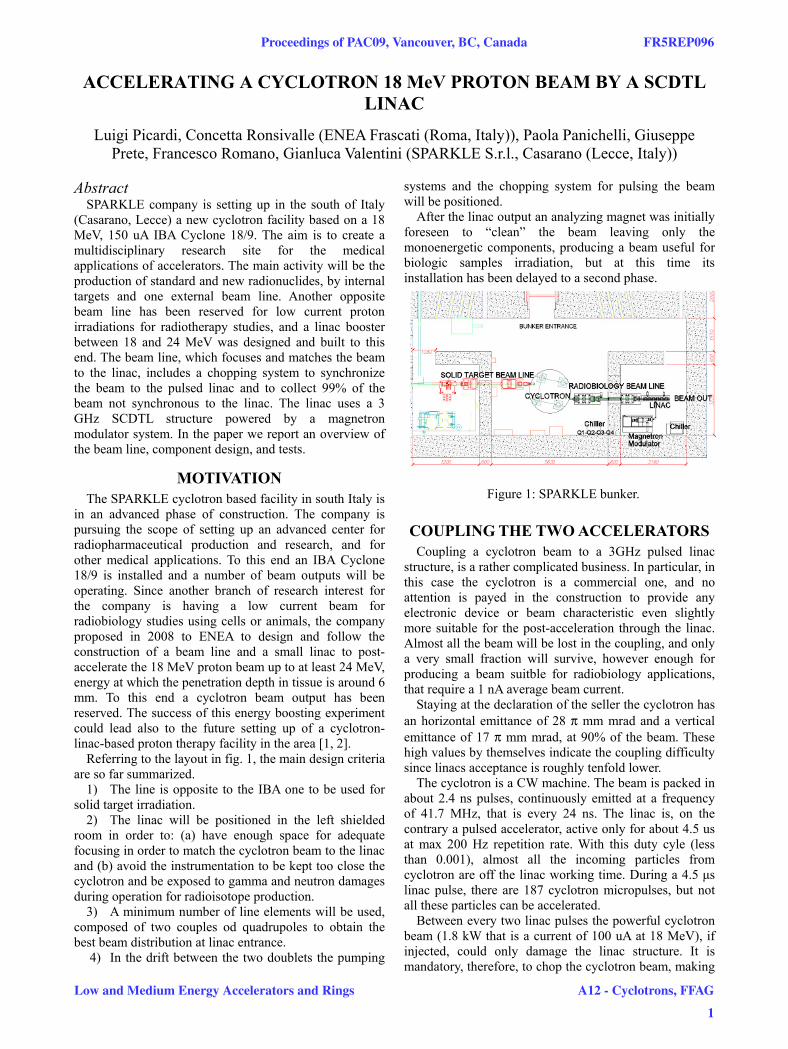
Referring to the layout in fig. 1, the main design criteria are so far summarized.
1) The line is opposite to the IBA one to be used for solid target irradiation.
2) The linac will be positioned in the left shielded room in order to: (a) have enough space for adequate focusing in order to match the cyclotron beam to the linac and (b) avoid the instrumentation to be kept too close the cyclotron and be exposed to gamma and neutron damages during operation for radioisotope production.
3) A minimum number of line elements will be used, composed of two couples od quadrupoles to obtain the best beam distribution at linac entrance.
4) In the drift between the two doublets the pumping
systems and the chopping system for pulsing the beam will be positioned.
After the linac output an analyzing magnet was initially foreseen to “clean” the beam leaving only the monoenergetic components, producing a beam useful for biologic samples irradiation, but at this time its installation has been delayed to a second phase.
Figure 1: SPARKLE bunker.
COUPLING THE TWO ACCELERATORS Coupling a cyclotron beam to a 3GHz pulsed linac
structure, is a rather complicated business. In particular, in this case the cyclotron is a commercial one, and no attention is payed in the construction to provide any electronic device or beam characteristic even slightly more suitable for the post-acceleration through the linac. Almost all the beam will be lost in the coupling, and only a very small fraction will survive, however enough for producing a beam suitble for radiobiology applications, that require a 1 nA average beam current.
Staying at the declaration of the seller the cyclotron has an horizontal emittance of 28 π mm mrad and a vertical emittance of 17 π mm mrad, at 90% of the beam. These high values by themselves indicate the coupling difficulty since linacs acceptance is roughly tenfold lower.
The cyclotron is a CW machine. The beam is packed in about 2.4 ns pulses, continuously emitted at a frequency of 41.7 MHz, that is every 24 ns. The linac is, on the contrary a pulsed accelerator, active only for about 4.5 us at max 200 Hz repetition rate. With this duty cyle (less than 0.001), almost all the incoming particles from cyclotron are off the linac working time. During a 4.5 μs linac pulse, there are 187 cyclotron micropulses, but not all these particles can be accelerated.
Between every two linac pulses the powerful cyclotron beam (1.8 kW that is a current of 100 uA at 18 MeV), if injected, could only damage the linac structure. It is mandatory, therefore, to chop the cyclotron beam, making
Proceedings of PAC09, Vancouver, BC, Canada FR5REP096
Low and Medium Energy Accelerators and Rings A12 - Cyclotrons, FFAG
1

Figure 2: SPARKLE radiobiology beam line.
this a pulsed beam synchronous with the linac accelerating field.
Since a pused device integrated in the cyclotron electronics (for example modulation of the dee field) could not be get from IBA company, for several reasons, the adopted solution is using a 50 Hz AC deflecting magnet positioned in between the two quadrupole doublets, that “paints” the beam in the vertical plane. A couple of collimators stop the beam except during the zero crossing. The output beam is therefore a 100 Hz pulsed beam. As the deflection of the magnet increases and the collimator size decreases, obviously the pulse duration decreases. A 50-100 rms μs pulse at 100 Hz repetition rate can be reached. This allows a duty cycle of the order of less than 2%, sufficient to avoid damages to the linac structure.
BEAM DYNAMICS The Twiss coefficients needed to match the input beam
to the linac have been derived from a first dynamic calculation based on the code DESIGN [3], that harmonizes the propagation of the reference particle with the electric and magnetic fields within the linac structure, using an ideal input beam and the permanet magnet qudrupoles set by the internal dynamics.
The following values of αx, βx, αy, βy were found, at the center of the first linac PMQ: αx = 0.0, βx = 0.577, αy = 0.0, βy = 0.18. By means of the TRACE3D code, the values of the four beam line quadrupoles have been derived, that satisfy the matching conditions: Q1=11.411 T/m; Q2= -10.735 T/m; Q3=12.947 T/m; Q4=-15.819 T/m. The four quads have a 150 mm effective length. The two doublets have a 160 mm drift between the two quads. The first two quads will have an aperture of 60 mm, while the second two quads it is possible to reduce it to 40 mm since the beam is already pulsed.
The complete line, included the linac but without acceleration, has been studied by TRACE3D and TRANSPORT (fig. 3) codes. It can be seen that the envelope slightly hits in some points the beam pipe walls. It overcomes also the limits imposed by the Linac PMQs dimensions. In fig. 3 the beam envelope is drawn inside the actual beam pipe limits.
A better beam loss analysis has been carried through
mainly by LINAC [3] code used for a full transport of the accelerated beam. LINAC requires values for 100% of the beam, that are ex, ey = 42.17, 25.52 π mm mrad.
Figure 3: TRANSPORT output.
The cyclotron beam distribution is not known, and two typical cases have been simulated: (a) a gaussian beam and (b) a 4 V uniform distribution in the hypervolume (x, x’, y, y’). In table 1 the particle transmission is tabulated versus the slit names, and their physical characteristics (Xmax and Ymax); the last row is the transmission through an hypotetical analyzing-cleaning magnet.
Table 1: Particle Transmission through Line SLIT Z
(mm) Xmax mm
Ymax mm
Transmission(%)
0 100 SMI 1203 4.5 25.0 100 SMO 1381 4.5 25.0 100 C2O 2453 25.0 2.0 85.4 LiI 3442 3 3 79.5 LiO 4757 3 3 16.9 AM 3.3
LINAC STRUCTURE The LINAC is a SCDTL (Side Coupled Drift Tube
Linac), operating at 3 GHz based on an ENEA patent [4]. This accelerating structure was developed since nineties in the framework of TERA activities and of the TOP project, which aimed to develop a protontherapy dedicated linac in Italy, and carried on mainly by ENEA, ISS (National Health Institute) and IFO (the main oncological hospital in Rome).
FR5REP096 Proceedings of PAC09, Vancouver, BC, Canada
Low and Medium Energy Accelerators and Rings
2
A12 - Cyclotrons, FFAG
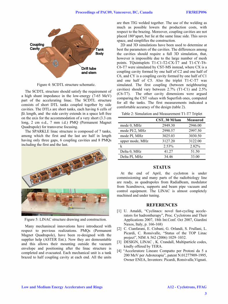
Figure 4: SCDTL structure schematic.
The SCDTL structure should satisfy the requirement of a high shunt impedance in the low-energy (7-65 MeV) part of the accelerating linac. The SCDTL structure consists of short DTL tanks coupled together by side cavities. The DTLs are short tanks, each having 6 cells of βλ length, and the side cavity extends in a space left free on the axis for the accommodation of a very short (3.3 cm long, 2 cm o.d., 7 mm i.d.) PMQ (Permanent Magnet Quadrupole) for transverse focusing.
The SPARKLE linac structure is composed of 7 tanks, among which the first and the last are half in length having only three gaps, 6 coupling cavities and 8 PMQs including the first and the last.
Figure 5: LINAC structure drawing and construction.
Many mechanincal innovations have introduced with respect to previous realizations. PMQs (Permanent Magnet Quadrupole), have been re-designed with the supplier help (ASTER Ent.). Now they are demountable and this allows their mounting outside the vacuum envelope and positioning after the linac structure is completed and evacuated. Each mechanical unit is a tank brazed to half coupling cavity at each end. All the units
are then TIG welded together. The use of the welding as much as possible lowers the production costs, with respect to the brazing. Moreover, coupling cavities are not placed 180°apart, but lie at the same linac side. This saves space, and simplifies the construction.
2D and 3D simulations have been used to determine at best the parameters of the cavities. The differences among the cavities should require a full 3D simulation, that, however is impossible due to the large number of mesh points. TQuintuplets T1-C1-T2-CX-T7 and T1-CY-T6-C6-T7 were simulated by CST-MS instead, where CX is a coupling cavity formed by one half of C2 and one half of C6, and CY is a coupling cavity formed by one half of C1 and one half of C5. Also the triplet T1-C-T7 was simulated. The first coupling (between neighbouring cavities) should vary between 2.7% (T1-C1) and 2.5% (C6-T7). The other cavity dimensions were argued comparing the CST values with Superfish ones, computed for all the tanks. The first measurements indicated a comfortable accuracy of the design (table 2).
Table 2: Simulation and Measurement T1-T7 Triplet CST, 30 M/lam Measured mode 0, MHz 2949.30 2946.00 mode PI/2, MHz 2990.57 2997.50 mode PI, MHz 3025.03 3030.50 upper mode, MHz 3127.20 3122.00 k 2.53% 2.82% Delta 0, MHz 41.27 51.50 Delta PI, MHz 34.46 33.00
STATUS At the end of April, the cyclotron is under
commissioning and many parts of the radiobiology line are ready, as quadrupoles from RadiaBeam, modulator from Scandinova, supports and beam pipe vacuum and control equipment. The LINAC is almost completely machined and under tuning.
REFERENCES [1] U. Amaldi, “Cyclinacs: novel fast-cycling accele-
rators for hadrontherapy”, Proc. Cyclotrons and Their Applications 2007, 18th Int.Conf. Oct 2007, Giardini Naxos, Italy, p. 166-168)
[2] C. Cianfarani, E. Cisbani, G. Orlandi, S. Frullani, L. Picardi, C. Ronsivalle, “Status of the TOP Linac project”, NIM A 562 (2006) 1029–1032.
[3] DESIGN, LINAC , K. Crandall, Multiparticle codes, kindly offered by TERA.
[4] “Acceleratore Lineare Compatto per Protoni da 5 a 200 MeV per Adroterapia”, patent N.01277909-1995, Owner ENEA, Inventors: Picardi, Ronsivalle,Vignati.
Proceedings of PAC09, Vancouver, BC, Canada FR5REP096
Low and Medium Energy Accelerators and Rings A12 - Cyclotrons, FFAG
3