a/c model development and validation - department of … · a/c model development and validation ....
TRANSCRIPT
NREL is a national laboratory of the U.S. Department of Energy, Office of Energy Efficiency and Renewable Energy, operated by the Alliance for Sustainable Energy, LLC.
A/C Model Development and Validation
P.I.: Jason A. Lustbader National Renewable Energy Laboratory Team: Larry Chaney Tibor Kiss May 16, 2012 Project ID VSS045
This presentation does not contain any proprietary, confidential, or otherwise restricted information.
2
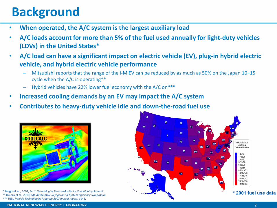
Background • When operated, the A/C system is the largest auxiliary load • A/C loads account for more than 5% of the fuel used annually for light-duty vehicles
(LDVs) in the United States* • A/C load can have a significant impact on electric vehicle (EV), plug-in hybrid electric
vehicle, and hybrid electric vehicle performance – Mitsubishi reports that the range of the i-MiEV can be reduced by as much as 50% on the Japan 10–15
cycle when the A/C is operating** – Hybrid vehicles have 22% lower fuel economy with the A/C on***
• Increased cooling demands by an EV may impact the A/C system • Contributes to heavy-duty vehicle idle and down-the-road fuel use
* Rugh et al., 2004, Earth Technologies Forum/Mobile Air Conditioning Summit ** Umezu et al., 2010, SAE Automotive Refrigerant & System Efficiency Symposium *** INEL, Vehicle Technologies Program 2007 annual report, p145.
* 2001 fuel use data
1014
19
7
37
78
64
9
187
43
735
179
17
127
15
238
66
109
229
273
61
52
167
22
40
12
219
17
85
144
86186
21
118
176
9575
142242
26
68
68
251
753
76730
216 86
167
1
7
37
78
64
9
187
43
735
179
17
127
15
238
66
109
229
273
61
52
167
22
40
12
219
17
85
144
86186
21
118
86
176
9575
142242
26
68
68
251
753
19
61
76730
216 86
167
1
Million GallonsCooling &
Dehumidification
1 to 1717 to 2626 to 5252 to 6868 to 7878 to 8686 to 142142 to 176176 to 216216 to 242242 to 730730 to 753
3
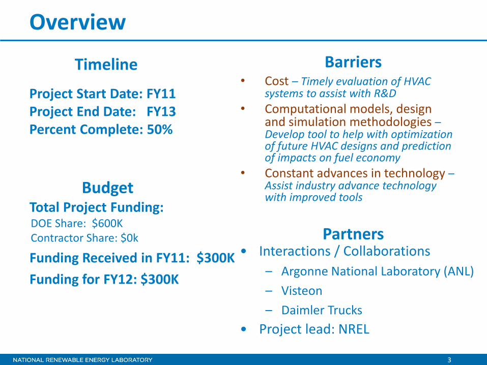
Overview
Project Start Date: FY11 Project End Date: FY13 Percent Complete: 50%
• Cost – Timely evaluation of HVAC systems to assist with R&D
• Computational models, design and simulation methodologies – Develop tool to help with optimization of future HVAC designs and prediction of impacts on fuel economy
• Constant advances in technology – Assist industry advance technology with improved tools
Total Project Funding: DOE Share: $600K Contractor Share: $0k
Funding Received in FY11: $300K Funding for FY12: $300K
Timeline
Budget
Barriers
• Interactions / Collaborations – Argonne National Laboratory (ANL) – Visteon – Daimler Trucks
• Project lead: NREL
Partners

4
Relevance/Objectives
• Overall Objectives – The objective of this project is to develop analysis tools to assess the
impact of technologies that reduce the thermal load, improve the climate control efficiency, and reduce vehicle fuel consumption
– Develop an open source, accurate, and transient air conditioning model using the Matlab®/Simulink® environment for co-simulation with Autonomie®
– Connect climate control, cabin thermal, and vehicle-level models to assess the impacts of advanced thermal management technologies on fuel use and range
• FY11/12 Objectives – Develop an LDV A/C model that simulates A/C performance and
generates mechanical or electrical loads – Validate A/C components and system performance with bench data – Demonstrate co-simulation of A/C system with Autonomie® – Release A/C model plug-in for Autonomie®

5
Milestones Date Milestone or Go/No-Go Decision
04/31/2010 Demonstrated CoolCalc A/C model framework
07/31/2011 Demonstrated Autonomie® integration
08/31/2011 DOE milestone report on A/C model status and preliminary results
04/01/2012 Delivered stand-alone model to Visteon
05/01/2012 Deliver electric A/C model to ANL
06/01/2012 Complete initial validation
09/30/2012 • Complete summary report and do first release of the A/C model
• SAE World Congress paper draft
Evaporator
Compressor
Condenser
Expansion Valve
Liquid
Vapor
Liquid + Vapor
Vapor
WarmAir
ColdAir
Fan
Receiver/Dryer
Liquid water
CoolingAir
0 100 200 300 400 500-2
-1
0
1
2
3
4
5
6
7
8
Pow
er [k
W]
Time [sec]
Com
pres
sor
Pow
er [k
W]
Time [sec]

6
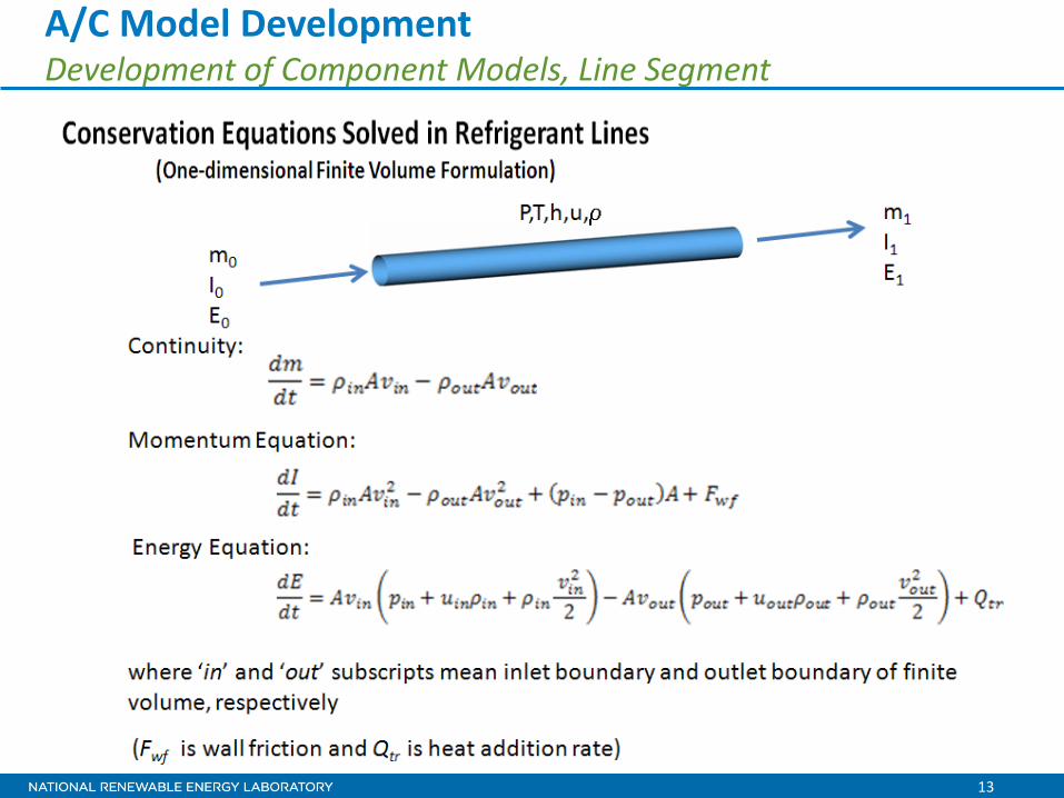
Approach – Matlab/Simulink-based tool • A simulation tool based on first principles; conservation of
mass, momentum, and energy are solved in 1-D finite volume formulation
• Tool will be open source and available to the public • Easily interfaced to Autonomie® vehicle simulation tool • Flexible software platform, capable of modeling vapor
compression refrigeration cycle • Model refrigerant lines and the heat exchangers as 1-D finite
volumes, accounting for the lengthwise distribution of refrigerant and flow properties
• Include all major components: compressor, condenser, expansion device, evaporator, and accumulator/dryer (receiver/dryer)
7
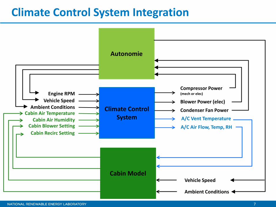
Climate Control System Integration
Climate Control System
Engine RPM Vehicle Speed
Cabin Air Temperature
Cabin Blower Setting
Ambient Conditions
Cabin Air Humidity
Compressor Power (mech or elec)
Blower Power (elec)
A/C Vent Temperature Condenser Fan Power
Cabin Recirc Setting A/C Air Flow, Temp, RH
Autonomie
Cabin Model Vehicle Speed
Ambient Conditions
8
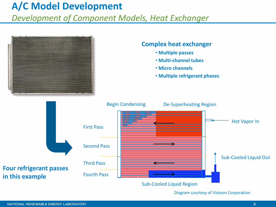
Diagram courtesy of Visteon Corporation
Complex heat exchanger • Multiple passes • Multi-channel tubes • Micro channels • Multiple refrigerant phases
A/C Model Development Development of Component Models, Heat Exchanger
Four refrigerant passes in this example
Hot Vapor In
Sub-Cooled Liquid Out
De-Superheating Region Begin Condensing
First Pass
Second Pass
Third Pass
Fourth Pass
Sub-Cooled Liquid Region
9
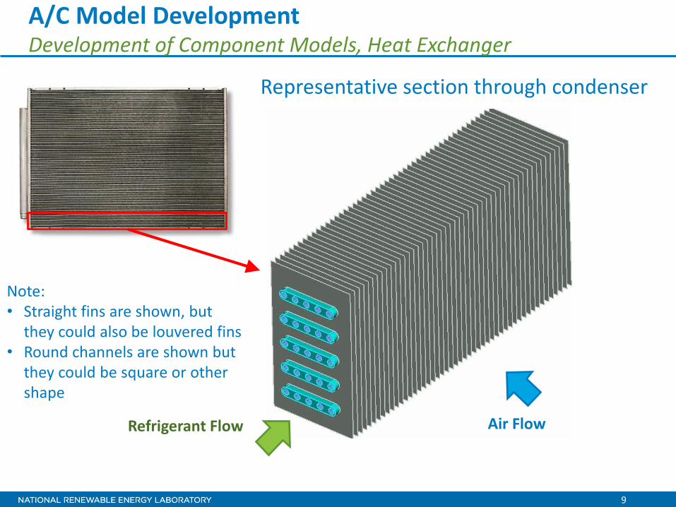
A/C Model Development Development of Component Models, Heat Exchanger
Representative section through condenser
Refrigerant Flow
Note: • Straight fins are shown, but
they could also be louvered fins • Round channels are shown but
they could be square or other shape
Air Flow
10
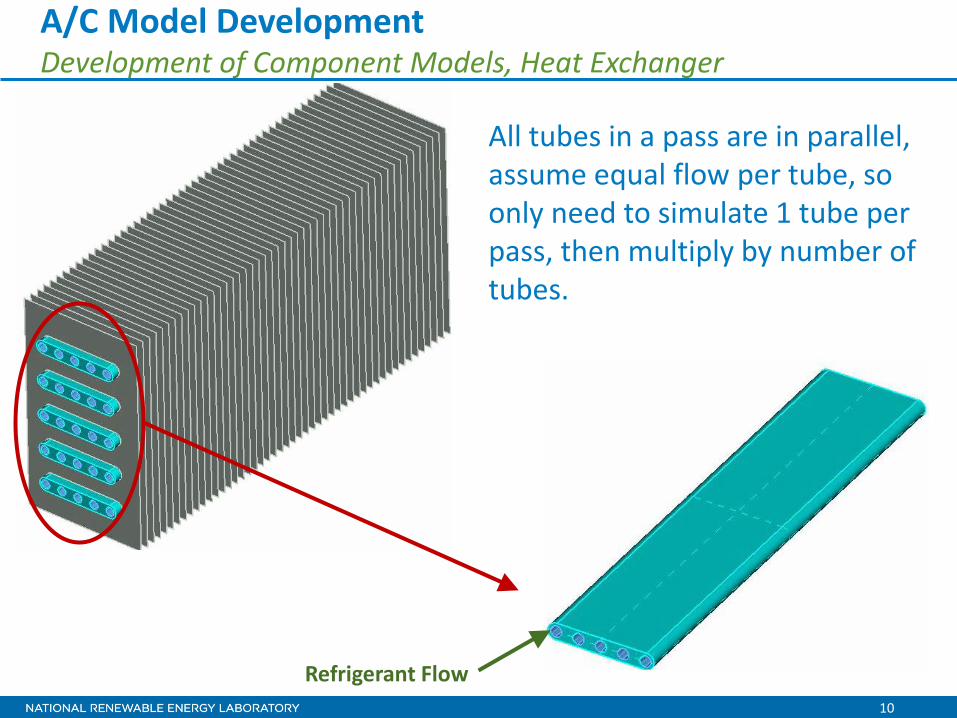
Refrigerant Flow
All tubes in a pass are in parallel, assume equal flow per tube, so only need to simulate 1 tube per pass, then multiply by number of tubes.
A/C Model Development Development of Component Models, Heat Exchanger
11
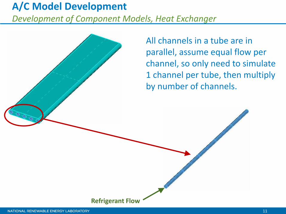
All channels in a tube are in parallel, assume equal flow per channel, so only need to simulate 1 channel per tube, then multiply by number of channels.
Refrigerant Flow
A/C Model Development Development of Component Models, Heat Exchanger

12
A/C Model Development Development of Component Models, Heat Exchanger • Four refrigerant passes become four flow paths in
this example • Each flow path is divided into many segments, or
finite volumes • The 1-D finite volumes account for the lengthwise
distribution of refrigerant and flow properties
13
A/C Model Development Development of Component Models, Line Segment
14
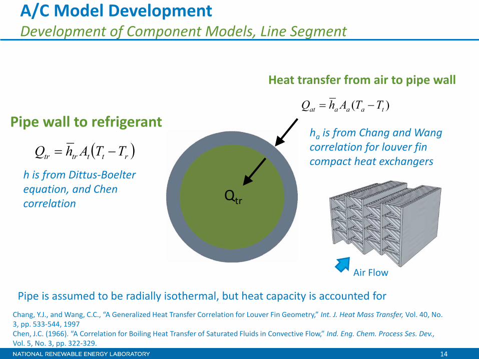
A/C Model Development Development of Component Models, Line Segment
Chang, Y.J., and Wang, C.C., “A Generalized Heat Transfer Correlation for Louver Fin Geometry,” Int. J. Heat Mass Transfer, Vol. 40, No. 3, pp. 533-544, 1997 Chen, J.C. (1966). “A Correlation for Boiling Heat Transfer of Saturated Fluids in Convective Flow,” Ind. Eng. Chem. Process Ses. Dev., Vol. 5, No. 3, pp. 322-329.
Qtr
Pipe is assumed to be radially isothermal, but heat capacity is accounted for
)( taaaat TTAhQ −=
ha is from Chang and Wang correlation for louver fin compact heat exchangers
Heat transfer from air to pipe wall
( )rtttrtr TTAhQ −=
Pipe wall to refrigerant
h is from Dittus-Boelter equation, and Chen correlation
Air Flow
15
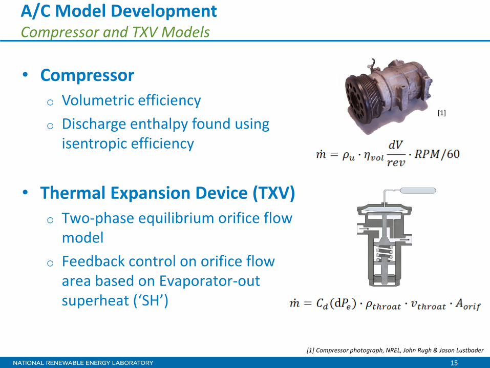
• Compressor o Volumetric efficiency o Discharge enthalpy found using
isentropic efficiency
• Thermal Expansion Device (TXV) o Two-phase equilibrium orifice flow
model o Feedback control on orifice flow
area based on Evaporator-out superheat (‘SH’)
A/C Model Development Compressor and TXV Models
[1]
[1] Compressor photograph, NREL, John Rugh & Jason Lustbader

16
Solar Load Convective Load
Thermal Mass
Fan Speed
Air recirculation and reheat (recirculation and blend door settings)
Heat Load from Engine Compartment
Cabin Air Exhaust
A/C Model Development Single Zone LDV Cabin Model
17
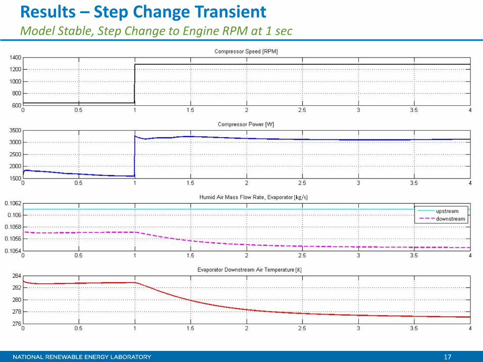
Results – Step Change Transient Model Stable, Step Change to Engine RPM at 1 sec
18
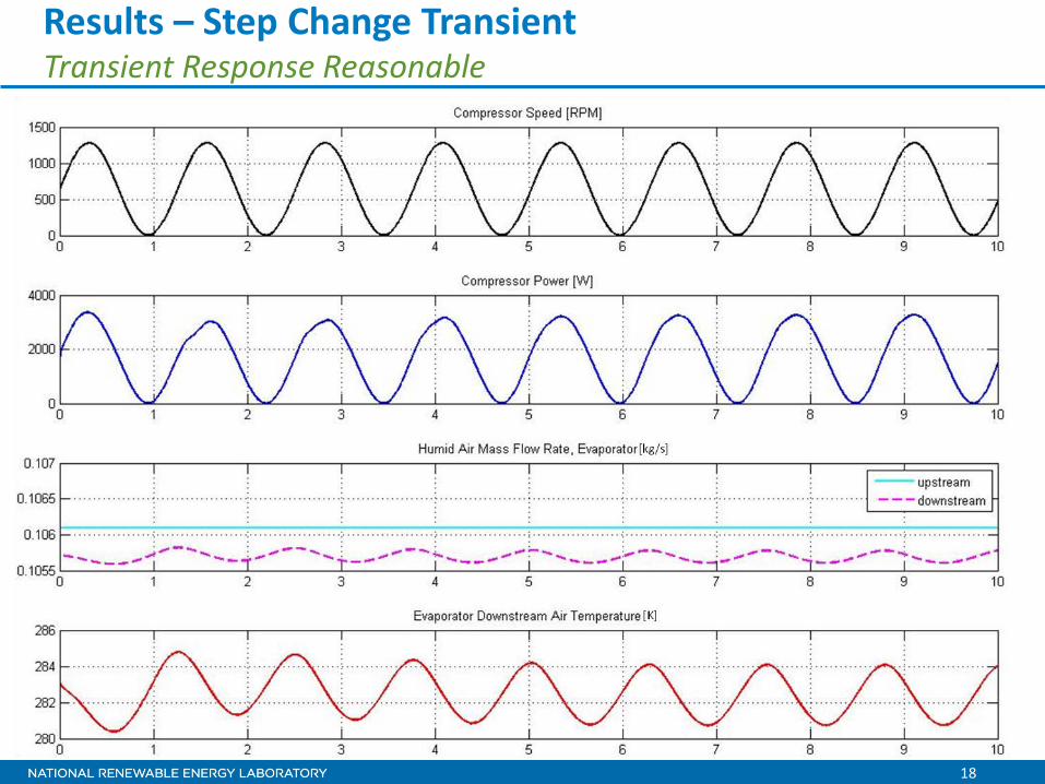
Results – Step Change Transient Transient Response Reasonable
19
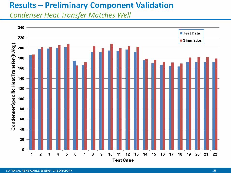
Results – Preliminary Component Validation Condenser Heat Transfer Matches Well
0
20
40
60
80
100
120
140
160
180
200
220
240
1 2 3 4 5 6 7 8 9 10 11 12 13 14 15 16 17 18 19 20 21 22
Con
dens
er S
peci
fic H
eat T
rans
fer (
kJ/k
g)
Test Case
Test Data
Simulation
20
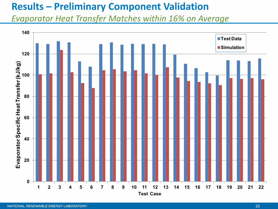
Results – Preliminary Component Validation Evaporator Heat Transfer Matches within 16% on Average
0
20
40
60
80
100
120
140
1 2 3 4 5 6 7 8 9 10 11 12 13 14 15 16 17 18 19 20 21 22
Evap
orat
or S
peci
fic H
eat T
rans
fer (
kJ/k
g)
Test Case
Test Data
Simulation
21
100 150 200 250 300 350 400 450 50010
1
102
103
104
Pre
ssur
e [k
Pa]
Specific Enthalpy [kJ/kg]
Thermodynamic Cycle on the P-h Diagram
mix boundarysimulatedmeasured
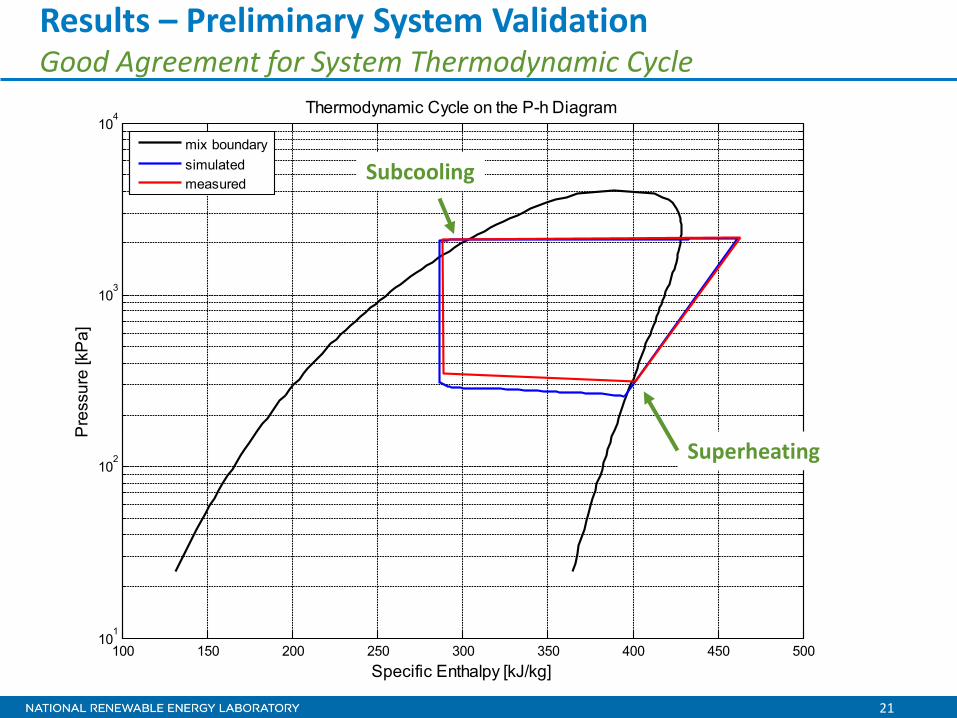
Results – Preliminary System Validation Good Agreement for System Thermodynamic Cycle
Superheating
Subcooling
22
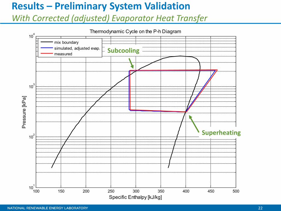
100 150 200 250 300 350 400 450 50010
1
102
103
104
Pre
ssur
e [k
Pa]
Specific Enthalpy [kJ/kg]
Thermodynamic Cycle on the P-h Diagram
mix boundarysimulated, adjusted evap.measured
Results – Preliminary System Validation With Corrected (adjusted) Evaporator Heat Transfer
Superheating
Subcooling
23
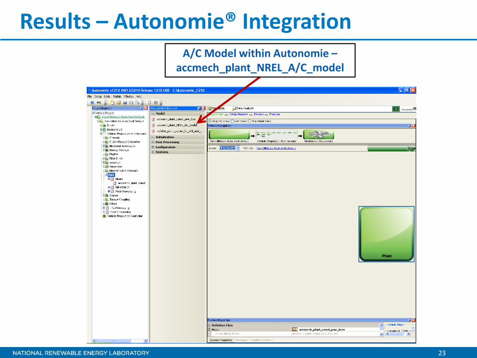
Results – Autonomie® Integration A/C Model within Autonomie –
accmech_plant_NREL_A/C_model

24
Results – Autonomie® Integration Top-Level Model
NREL A/C Model
25
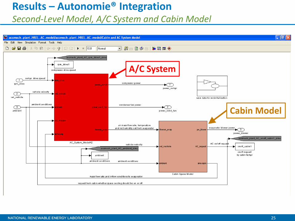
Results – Autonomie® Integration Second-Level Model, A/C System and Cabin Model
A/C System
Cabin Model
26
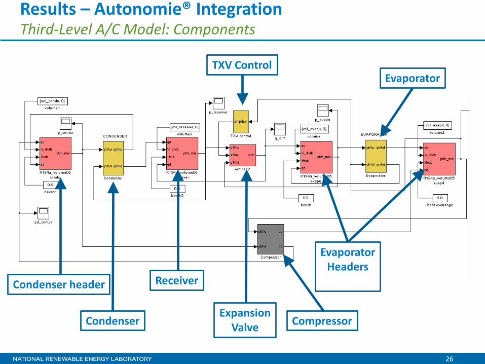
Results – Autonomie® Integration Third-Level A/C Model: Components
Condenser header
Condenser
Receiver
Expansion Valve Compressor
Evaporator Headers
Evaporator TXV Control

27
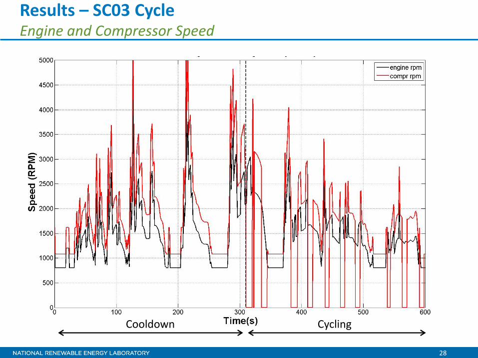
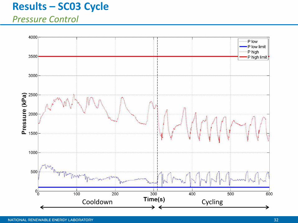
• Simulated the A/C system incorporated in a vehicle – Used SC03 drive cycle – Conventional 2wd Midsize Auto Default in Autonomie® – Demonstrated robust system performance and cabin
cooldown • Conditions and Controls Settings
– Ambient temperature: 40°C – Cabin initial temperature: 60°C – Cabin initial relative humidity: 50% – Solar load: 1,300 W – Cabin target temperature: 20°C – Air Recirculation: 95%
Results – SC03 Cycle System Model SC03 Example
28
Results – SC03 Cycle Engine and Compressor Speed
Cooldown Cycling
29
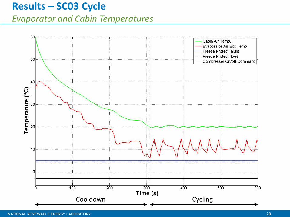
Results – SC03 Cycle Evaporator and Cabin Temperatures
Cooldown Cycling
30
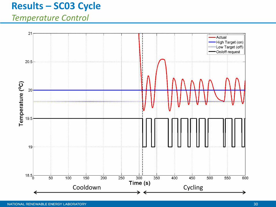
Results – SC03 Cycle Temperature Control
Cooldown Cycling
31
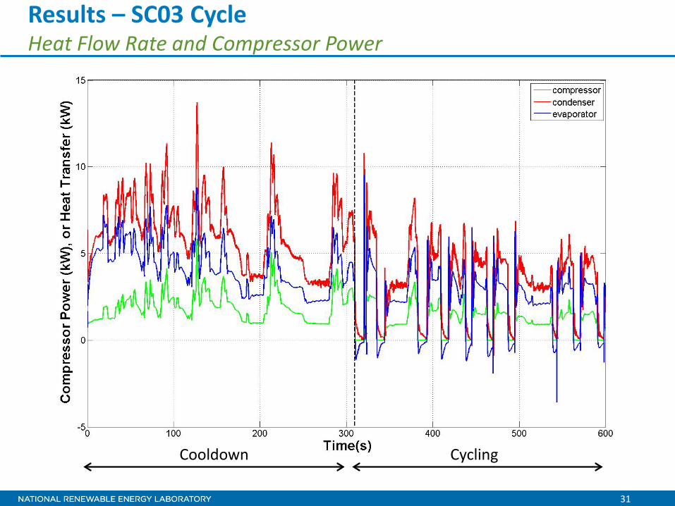
Results – SC03 Cycle Heat Flow Rate and Compressor Power
Cooldown Cycling
32
Results – SC03 Cycle Pressure Control
Cooldown Cycling

33
Collaboration
• Argonne National Laboratory – Integration of A/C model into
Autonomie® – Vehicle test data
• Visteon Corporation – Technical advice – A/C system and component
test data
• Daimler Trucks – Support Super Truck work
1. Diagram courtesy of Visteon Corporation 2. Daimler Super Truck Logo, Courtesy of Daimler Trucks, 2011
1
2
34
Future Work
FY12 • Complete model validation • Develop electric A/C model for Autonomie® • Develop a large-vehicle A/C model • Release publicly available Autonomie® plug-in
FY13
• Write user guide • Develop A/C model for heavy-duty vehicles • Add heating into the model • Apply to light- and heavy-duty vehicles
35
Summary
• A/C use can account for significant portion of the energy used by light-duty and heavy-duty vehicles.
• Reducing A/C energy use is essential to achieving the President’s goal of 1 million electric drive vehicles by 2015.
Approach • Develop a transient open source Matlab®/Simulink®-
based HVAC model that is both flexible and accurate. Base model on first principles and do not rely on component flow and heat transfer data as input.
• Interface HVAC model with Autonomie® vehicle simulation tool to simulate effects of HVAC use on vehicle efficiency and range.
DOE Mission Support
36
Summary
• Developed a Matlab®/Simulink® model of light-duty vehicle A/C system
– 1-D finite volume basic line building block – Developed A/C system components – Demonstrated and verified A/C system performance – Modifiable system and components based on input parameters
• Developed and demonstrated cabin model • Interfaced to Autonomie® • Validation in progress
Technical Accomplishments
Collaboration • Argonne National Laboratory • Visteon Corporation • Daimler Trucks
37
• U.S. Department of Energy – Patrick Davis, Vehicle Technologies Program – Lee Slezak, Vehicle Technologies Program – David Anderson, Vehicle Technologies Program
• NREL – Barbara Goodman, Director, Center for Transportation
Technologies and Systems – Terry Penney, NREL Vehicle Technologies Program Technology
Manager – Rob Farrington, Group Manager – John Rugh
• Visteon Corporation – John Meyer
• Argonne National Laboratory – Aymeric Rousseau
Summary – Acknowledgments

Technical Back-Up Slides
(Note: please include this “separator” slide if you are including back-up technical slides (maximum of five). These back-up technical slides will be available for your presentation and will be included in the DVD and Web PDF files released to the public.)
39
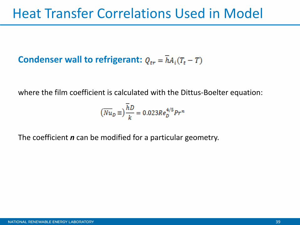
Condenser wall to refrigerant:
where the film coefficient is calculated with the Dittus-Boelter equation:
The coefficient n can be modified for a particular geometry.
Heat Transfer Correlations Used in Model
40
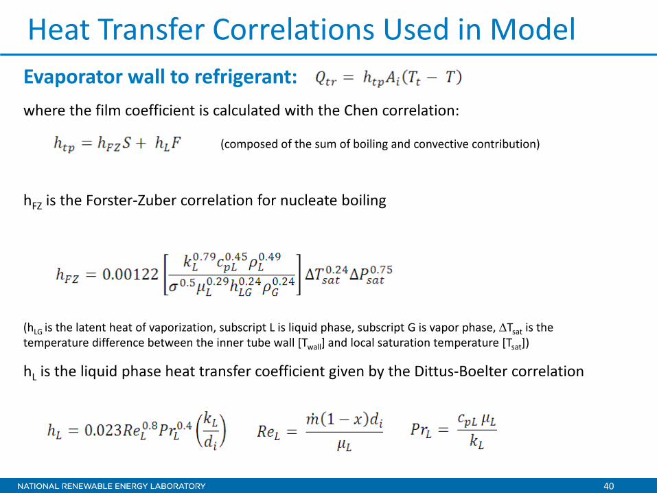
Evaporator wall to refrigerant: where the film coefficient is calculated with the Chen correlation:
(composed of the sum of boiling and convective contribution)
hFZ is the Forster-Zuber correlation for nucleate boiling
(hLG is the latent heat of vaporization, subscript L is liquid phase, subscript G is vapor phase, ∆Tsat is the temperature difference between the inner tube wall [Twall] and local saturation temperature [Tsat])
hL is the liquid phase heat transfer coefficient given by the Dittus-Boelter correlation
Heat Transfer Correlations Used in Model
41
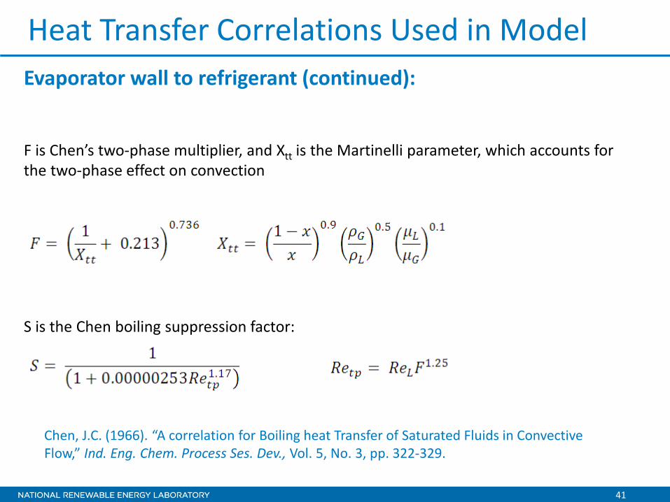
Heat Transfer Correlations Used in Model Evaporator wall to refrigerant (continued):
F is Chen’s two-phase multiplier, and Xtt is the Martinelli parameter, which accounts for the two-phase effect on convection
S is the Chen boiling suppression factor:
Chen, J.C. (1966). “A correlation for Boiling heat Transfer of Saturated Fluids in Convective Flow,” Ind. Eng. Chem. Process Ses. Dev., Vol. 5, No. 3, pp. 322-329.
42
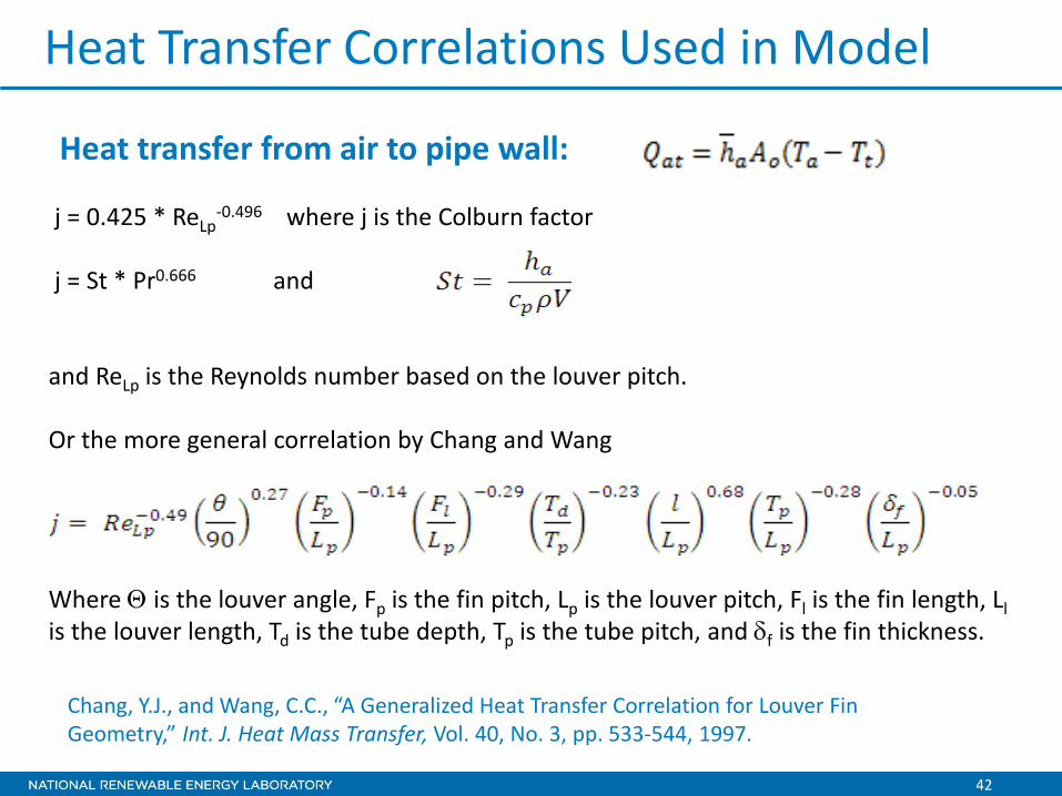
Chang, Y.J., and Wang, C.C., “A Generalized Heat Transfer Correlation for Louver Fin Geometry,” Int. J. Heat Mass Transfer, Vol. 40, No. 3, pp. 533-544, 1997.
Heat transfer from air to pipe wall:
Heat Transfer Correlations Used in Model
j = 0.425 * ReLp-0.496 where j is the Colburn factor
j = St * Pr0.666 and and ReLp is the Reynolds number based on the louver pitch. Or the more general correlation by Chang and Wang Where Θ is the louver angle, Fp is the fin pitch, Lp is the louver pitch, Fl is the fin length, Ll is the louver length, Td is the tube depth, Tp is the tube pitch, and δf is the fin thickness.
43
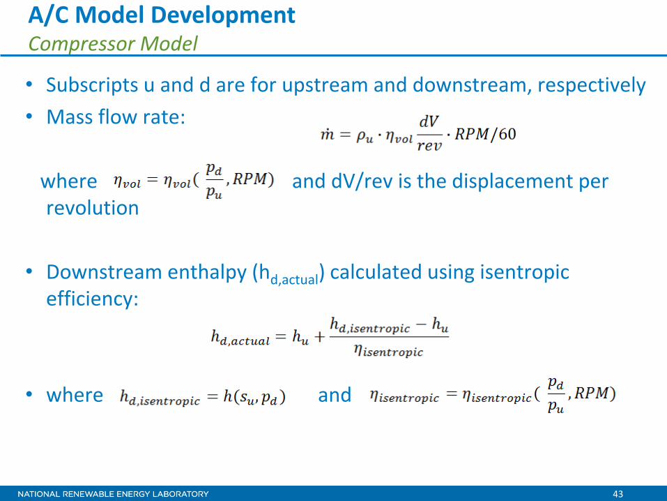
A/C Model Development Compressor Model • Subscripts u and d are for upstream and downstream, respectively • Mass flow rate: where and dV/rev is the displacement per
revolution • Downstream enthalpy (hd,actual) calculated using isentropic
efficiency: • where and

44
• Two-phase equilibrium orifice flow model with feedback control on orifice flow area based on Evaporator-out superheat (‘SH’)
• Orifice flow model calibrated to measured data using a discharge coefficient that is dependent on dPe
• Feedback control: • Large C results in quick convergence but may lead to hunting • Small C results in slow convergence but avoids hunting
A/C Model Development Thermal Expansion Valve (TXV) Model
100 150 200 250 300 350 400 45010
1
102
103
104
Pre
ssur
e [k
Pa]
Specific Enthalpy [kJ/kg]
dPe = Pu – Psat(hu) Pu
Psat(hu) Pd
Hu