about the speaker - netcraftsmen.com · so why are we using mplstransit bgp networks mpls is good...
TRANSCRIPT
Copyright © 2010, Chesapeake Netcraftsmen Handout Page-1
Introduction to MPLS
Paul Borghese,Chesapeake Netcraftsmen
Copyright 20101
Chesapeake [email protected]
About the Speaker
• Paul Borghese– Cisco CCIE #3760, CCSI #97115,– Specialties: Large-Scale Routing & Switching,
High Availability, Security– Taught many of the Cisco courses plus some
course development– Consultant to large federal and enterprise
li t
Copyright 20102
clients– Founder of GroupStudy.com
Copyright © 2010, Chesapeake Netcraftsmen Handout Page-2
Agenda
• Why Use MPLS?• Label Distribution Protocol
D t ti– Demonstration• Transit Area BGP Considerations
– Penultimate Hop Popping– Demonstration
• VPN Considerations– Demonstration
Copyright 2010
• Multi-VRF Considerations• AToM Considerations• Traffic Engineering Considerations
3
Agenda
• Why Use MPLS?• Label Distribution Protocol
D t ti– Demonstration• Transit Area BGP Considerations
– Penultimate Hop Popping– Demonstration
• VPN Considerations– Demonstration
Copyright 2010
• Multi-VRF Considerations• AToM Considerations• Traffic Engineering Considerations
4
Copyright © 2010, Chesapeake Netcraftsmen Handout Page-3
More on Why Use MPLS
So why are we using MPLSTransit BGP Networks
MPLS isGood for
NetworksSell VPN services to our customers
Traffic Engineer
Copyright 20105
gpathways through the network
MPLS Applications•EWAN •Edge
•Service •Providers
•Enterprise Data •Center
•Data center interconnects
•L2/L3VPN’s•TE/FRR
•VPN’s / VRF’s
atur
es •VPN’s / VRF’s•VPN’s
•QoS•High Availability
•VRF-Aware Security•High Availability
•Hosted Data centers•Data center interconnect
•Segmentation for IT •Mergers,
Acquisitions, spinoffs
•App
licat
ions
•Key
Fea
•Departmental segmentation
• Service multiplexing• Security•Mergers,
Acquisitions, spinoffs
•Disaster Recovery•Vmotion support
•Branch Interconnects
•Internet Access•Branch Connectivity
•VRF Aware Security•High Availability
•TE/FRR•High Availability
Copyright 2010•••••
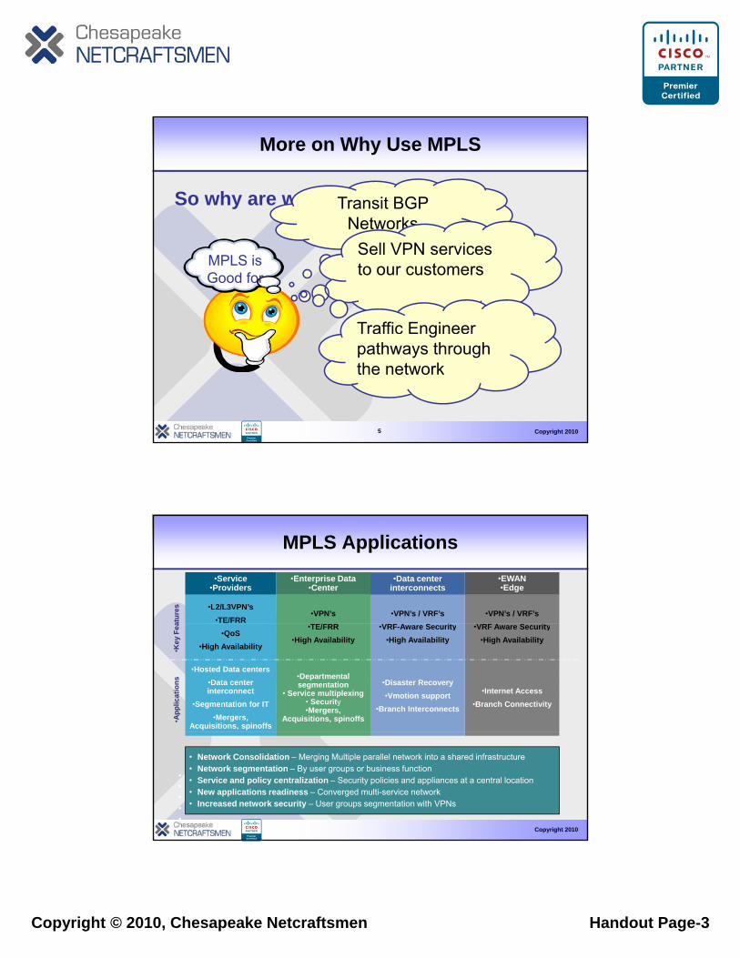
• Network Consolidation – Merging Multiple parallel network into a shared infrastructure• Network segmentation – By user groups or business function• Service and policy centralization – Security policies and appliances at a central location• New applications readiness – Converged multi-service network • Increased network security – User groups segmentation with VPNs
Copyright © 2010, Chesapeake Netcraftsmen Handout Page-4
MPLS Domain
MPLS Network Overview
PPCE
CE
CE
CE
•Label switched traffic
P
P
P
P
PE
PE PE
PE
Copyright 2010
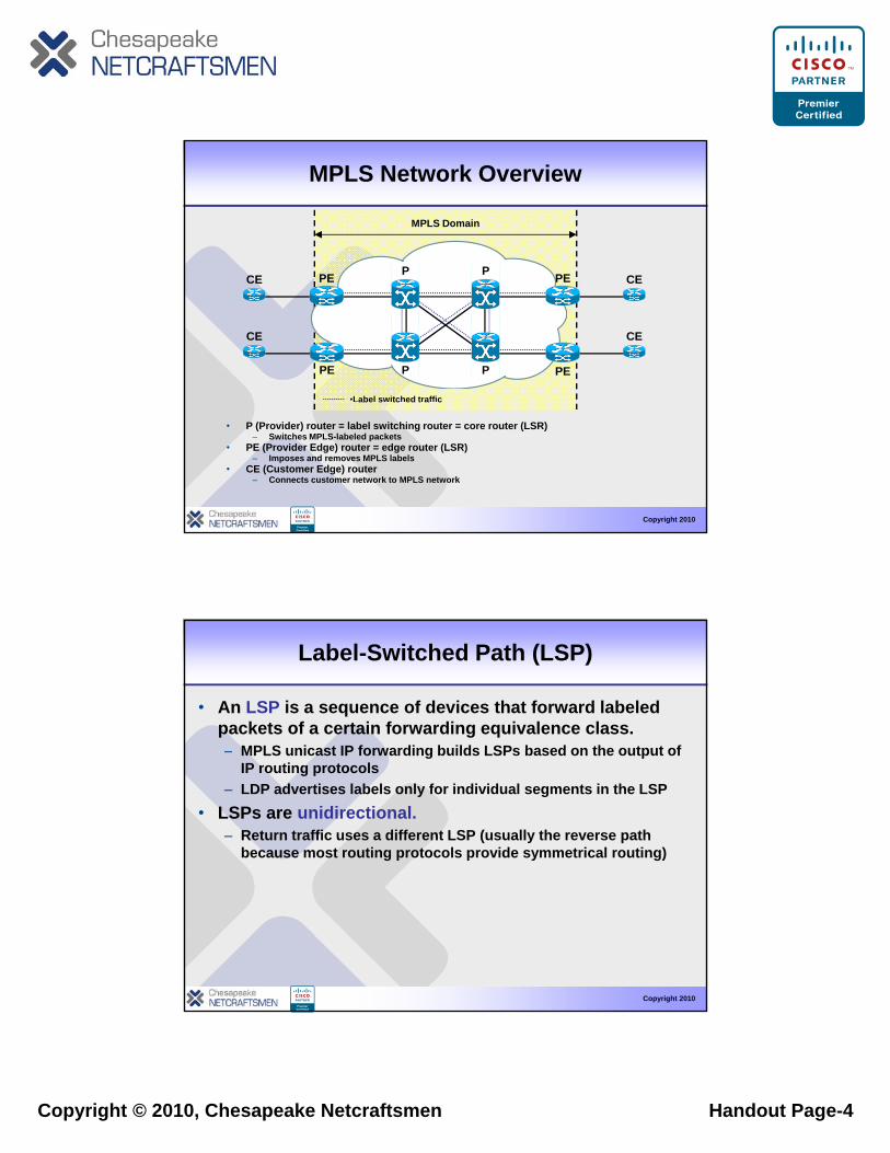
• P (Provider) router = label switching router = core router (LSR)– Switches MPLS-labeled packets
• PE (Provider Edge) router = edge router (LSR)– Imposes and removes MPLS labels
• CE (Customer Edge) router – Connects customer network to MPLS network
abe s tc ed t a c
Label-Switched Path (LSP)
• An LSP is a sequence of devices that forward labeled packets of a certain forwarding equivalence class.
MPLS unicast IP forwarding builds LSPs based on the output of– MPLS unicast IP forwarding builds LSPs based on the output of IP routing protocols
– LDP advertises labels only for individual segments in the LSP• LSPs are unidirectional.
– Return traffic uses a different LSP (usually the reverse path because most routing protocols provide symmetrical routing)
Copyright 2010
Copyright © 2010, Chesapeake Netcraftsmen Handout Page-5
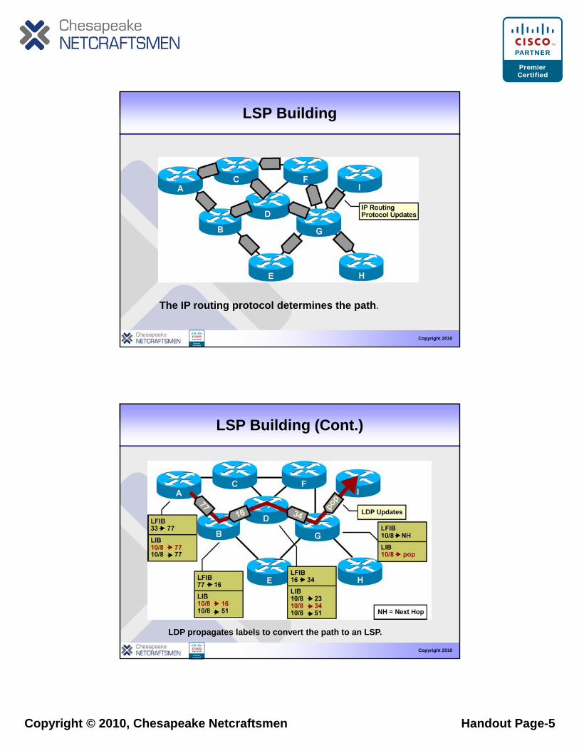
LSP Building
Copyright 2010
The IP routing protocol determines the path.
LSP Building (Cont.)
Copyright 2010
LDP propagates labels to convert the path to an LSP.
Copyright © 2010, Chesapeake Netcraftsmen Handout Page-6
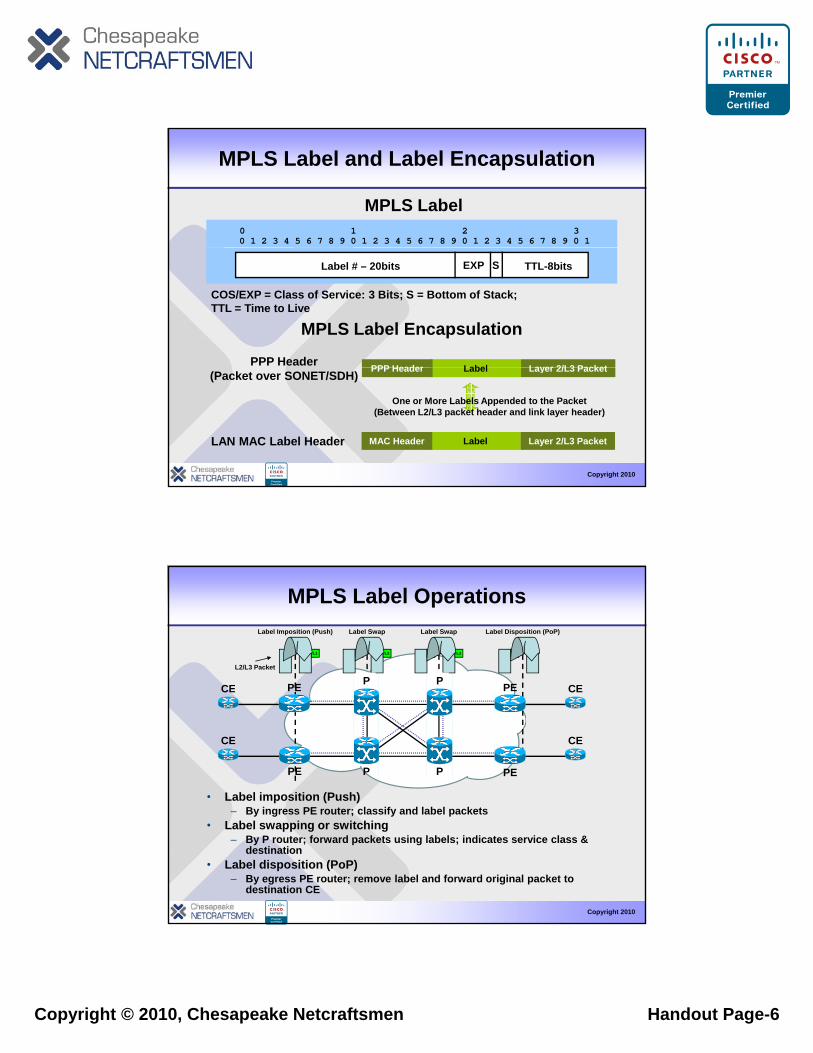
MPLS Label and Label Encapsulation
0 1 2 30 1 2 3 4 5 6 7 8 9 0 1 2 3 4 5 6 7 8 9 0 1 2 3 4 5 6 7 8 9 0 1
MPLS Label
COS/EXP = Class of Service: 3 Bits; S = Bottom of Stack; TTL = Time to Live
Label # – 20bits EXP S TTL-8bits
LabelPPP Header Layer 2/L3 PacketPPP Header
MPLS Label Encapsulation
Copyright 2010
LabelPPP Header Layer 2/L3 Packet(Packet over SONET/SDH)
One or More Labels Appended to the Packet(Between L2/L3 packet header and link layer header)
LAN MAC Label Header LabelMAC Header Layer 2/L3 Packet
MPLS Label Operations
CE CEPE
L1
Label Imposition (Push)
L2/L3 Packet
L1 L2
Label Swap
P
L2 L3
Label Swap
PE
L3
Label Disposition (PoP)
P
• Label imposition (Push)
CE
CE
CE
CE
PP PE
PE
PE
PE
Copyright 2010
– By ingress PE router; classify and label packets• Label swapping or switching
– By P router; forward packets using labels; indicates service class & destination
• Label disposition (PoP)– By egress PE router; remove label and forward original packet to
destination CE
Copyright © 2010, Chesapeake Netcraftsmen Handout Page-7
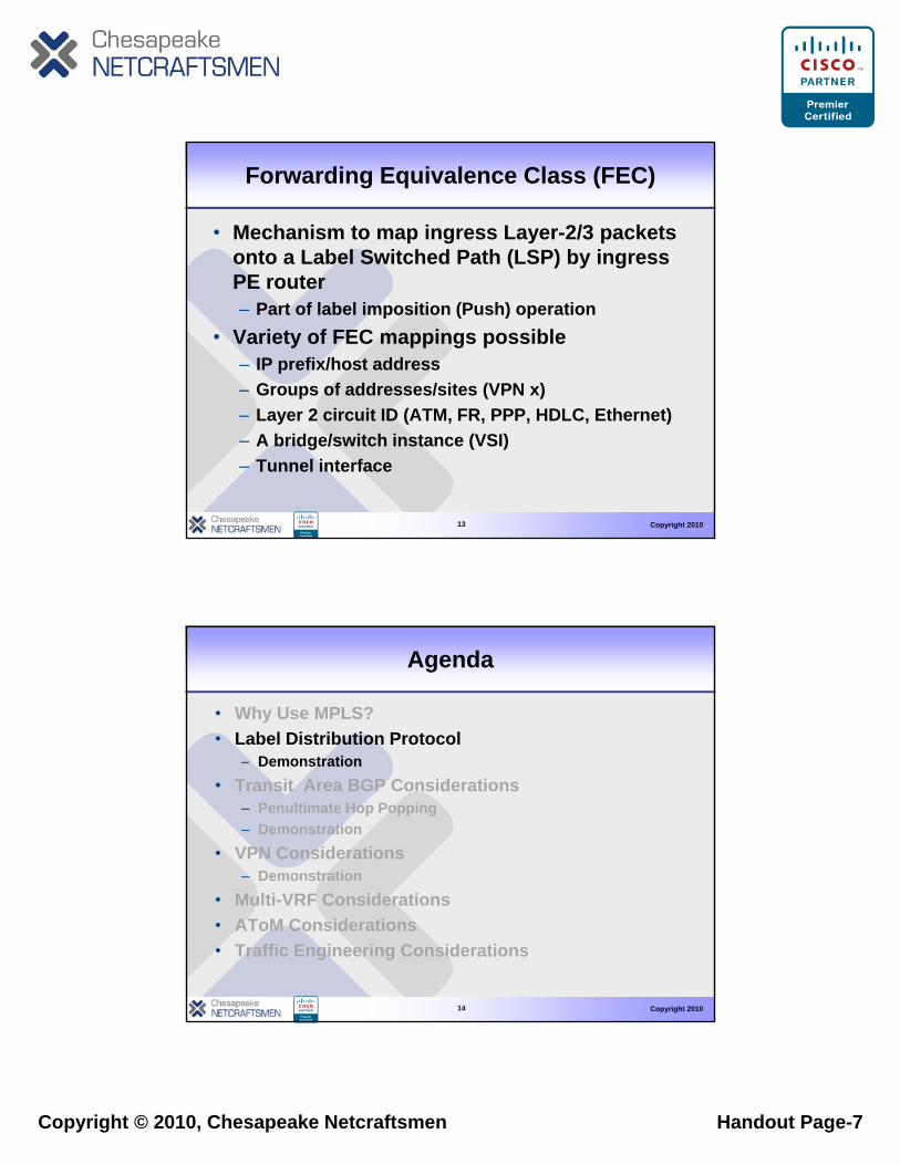
Forwarding Equivalence Class (FEC)
• Mechanism to map ingress Layer-2/3 packets onto a Label Switched Path (LSP) by ingress PE router– Part of label imposition (Push) operation
• Variety of FEC mappings possible– IP prefix/host address– Groups of addresses/sites (VPN x)
Copyright 2010
– Layer 2 circuit ID (ATM, FR, PPP, HDLC, Ethernet)– A bridge/switch instance (VSI)– Tunnel interface
13
Agenda
• Why Use MPLS?• Label Distribution Protocol
D t ti– Demonstration• Transit Area BGP Considerations
– Penultimate Hop Popping– Demonstration
• VPN Considerations– Demonstration
Copyright 2010
• Multi-VRF Considerations• AToM Considerations• Traffic Engineering Considerations
14
Copyright © 2010, Chesapeake Netcraftsmen Handout Page-8
Label Distribution Protocol (LDP)
• MPLS nodes need to exchange label information with each other– Ingress PE node (Push operation)
• Needs to know what label to use for a given FEC to send packet to neighbor
– Core P node (Swap operation)• Needs to know what label to use for swap
operation for incoming labeled packets
Copyright 2010
operation for incoming labeled packets – Egress PE node (Pop operation)
• Needs to tell upstream neighbor what label to use for specific FEC type LDP used for exchange of label (mapping) information
15
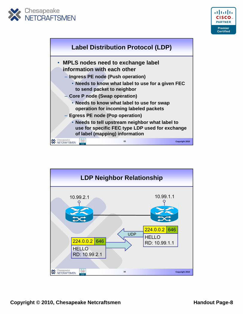
LDP Neighbor Relationship
10.99.1.110.99.2.1
646224.0.0.2HELLO
UDP
646224 0 0 2
Copyright 201016
RD: 10.99.1.1646224.0.0.2HELLORD: 10.99.2.1
Copyright © 2010, Chesapeake Netcraftsmen Handout Page-9
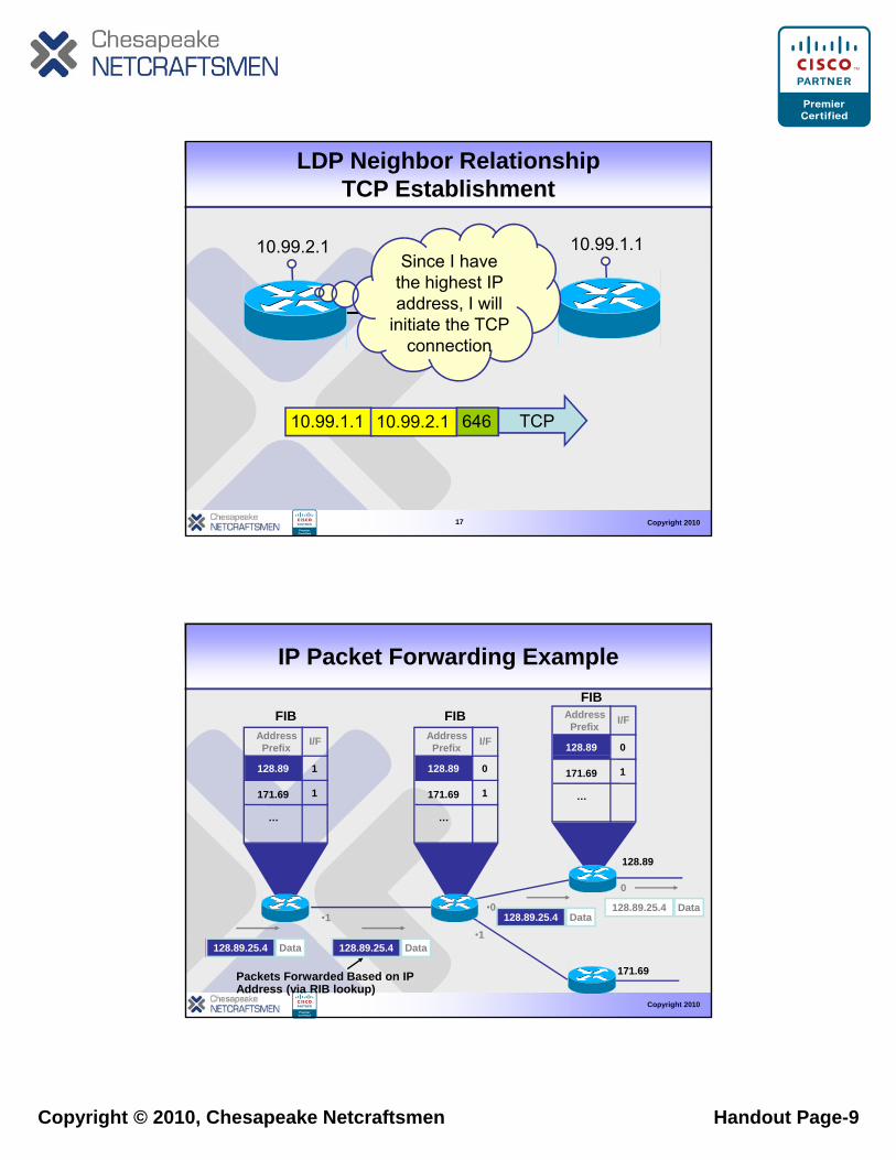
LDP Neighbor RelationshipTCP Establishment
10.99.1.110.99.2.1Since I have
the highest IP address, I will
initiate the TCP connection
Copyright 201017
64610.99.1.1 10.99.2.1 TCP
IP Packet Forwarding Example
AddressPrefix I/F Address
Prefix I/F 128.89
AddressPrefix I/F
0
FIB FIBFIB
128.89
0
…
128.89
171.69
1
1
…
128.89
171.69
0
1 …
171.69 1
Copyright 2010
•0
•1•1
171.69
0
128.89.25.4 Data
128.89.25.4 Data128.89.25.4 Data
128.89.25.4 Data
Packets Forwarded Based on IP Address (via RIB lookup)
Copyright © 2010, Chesapeake Netcraftsmen Handout Page-10
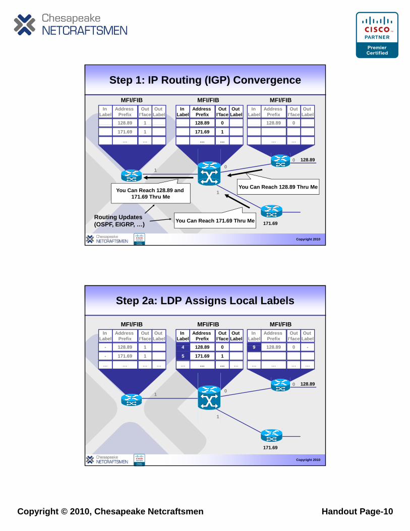
Step 1: IP Routing (IGP) Convergence
In Label
Address Prefix
OutI’face
128.89 1
Out Label
In Label
Address Prefix
OutI’face
128.89 0
Out Label
In Label
Address Prefix
128.89
OutI’face
0
Out Label
MFI/FIB MFI/FIB MFI/FIB
128.890
1
…
171.69 1
… …
171.69 1
… … …
0
Y C R h 128 89 Th M
Copyright 2010
171.69
1
You Can Reach 171.69 Thru Me
You Can Reach 128.89 and 171.69 Thru Me
Routing Updates (OSPF, EIGRP, …)
You Can Reach 128.89 Thru Me
In Label
Address Prefix
128 89
OutI’face
1
Out Label
In Label
Address Prefix
128 89
OutI’face
0
Out Label
In Label
Address Prefix
128 89
OutI’face
0
Out Label
4 9
Step 2a: LDP Assigns Local Labels
MFI/FIB MFI/FIB MFI/FIB
128.890
1
0
128.89
171.69
…
1
1
…
128.89
171.69
…
0
1
…
128.89
…
0
……
-
-
… …
4
5
…
-
…
9
…
Copyright 2010
1
171.69
Copyright © 2010, Chesapeake Netcraftsmen Handout Page-11
In Label
Address Prefix
128.89
OutI’face
1
Out Label
In Label
Address Prefix
128.89
OutI’face
0
Out Label
In Label
Address Prefix
128.89
OutI’face
0
Out Label
4- 94 -9
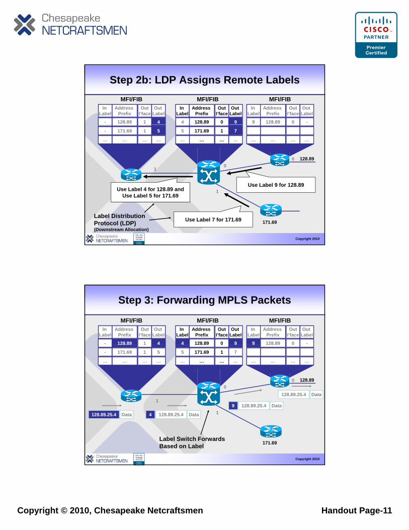
Step 2b: LDP Assigns Remote LabelsMFI/FIB MFI/FIB MFI/FIB
128.890
1
0
Use Label 9 for 128 89
171.69
…
1
…
171.69
…
1
… … …
5
…
-
…
7
…
5
… ……
Copyright 2010
1Use Label 9 for 128.89
Use Label 4 for 128.89 andUse Label 5 for 171.69
Label Distribution Protocol (LDP)(Downstream Allocation)
171.69Use Label 7 for 171.69
In Label
Address Prefix
128.89
OutI’face
1
Out Label
In Label
Address Prefix
128.89
OutI’face
0
Out Label
In Label
Address Prefix
128.89
OutI’face
0
Out Label
4- 94 -9
Step 3: Forwarding MPLS Packets
MFI/FIB MFI/FIB MFI/FIB
0
1128 89 25 4 Data9
128.89.25.4 Data
128.890
8 89
171.69
…
1
…
8 89
171.69
…
0
1
…
8 89
…
0
…
5
…
-
…
9
7
…
5
… …
9
…
Copyright 2010
1128.89.25.4 Data 128.89.25.4 Data4
128.89.25.4 Data9
Label Switch Forwards Based on Label 171.69
Copyright © 2010, Chesapeake Netcraftsmen Handout Page-12
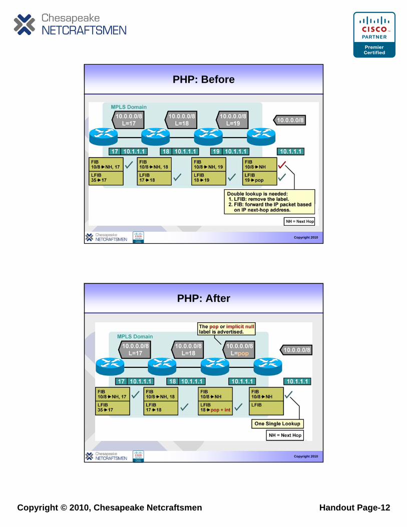
PHP: Before
Copyright 2010
– Double lookup is not an optimal way of forwarding labeled packets.
– A label can be removed one hop earlier.
PHP: After
Copyright 2010
• A label is removed on the router before the last hop within an MPLS domain.
Copyright © 2010, Chesapeake Netcraftsmen Handout Page-13
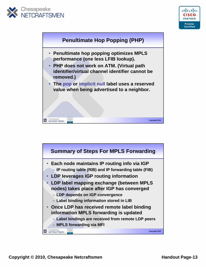
Penultimate Hop Popping (PHP)
• Penultimate hop popping optimizes MPLS performance (one less LFIB lookup).
• PHP does not work on ATM. (Virtual path identifier/virtual channel identifier cannot be removed.)
• The pop or implicit null label uses a reserved value when being advertised to a neighbor.
Copyright 2010
Summary of Steps For MPLS Forwarding
• Each node maintains IP routing info via IGP– IP routing table (RIB) and IP forwarding table (FIB)
• LDP leverages IGP routing information• LDP label mapping exchange (between MPLS
nodes) takes place after IGP has converged– LDP depends on IGP convergence– Label binding information stored in LIB
Copyright 2010
• Once LDP has received remote label binding information MPLS forwarding is updated– Label bindings are received from remote LDP peers– MPLS forwarding via MFI
Copyright © 2010, Chesapeake Netcraftsmen Handout Page-14
Demonstration of LDP
Copyright 201027
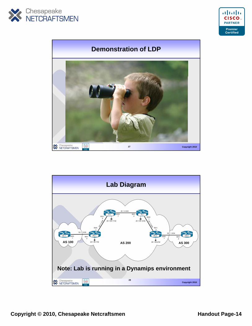
Lab Diagram
20.1.2.0/24
AS 300AS 200AS 100
CE-1 CE-2PE-2
P-2P-1
CE-1 PE-1
10.1.1.0/30
20.1
.1.0
/24 20.1.3.0/24
30.1.1.0/24
E0/0:.1
E0/0:.1
E0/0:.1
E0/1:.2
E0/1:.2
E0/0:.1
E0/1:.2
E0/1:.2
E0/0:.1
E0/1:.2
20.1.99.1/32 20.1.99.2/32
20.1.99.11/32 20.1.99.12/32
Copyright 201028
Note: Lab is running in a Dynamips environment
Copyright © 2010, Chesapeake Netcraftsmen Handout Page-15
Agenda
• Why Use MPLS?• Label Distribution Protocol
D t ti– Demonstration• Transit Area BGP Considerations
– Penultimate Hop Popping– Demonstration
• VPN Considerations– Demonstration
Copyright 2010
• Multi-VRF Considerations• AToM Considerations• Traffic Engineering Considerations
29
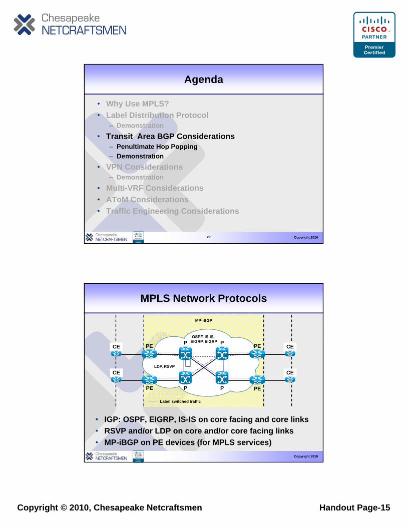
MPLS Network Protocols
PPOSPF, IS-IS,
EIGRP, EIGRP
MP-iBGP
Label switched traffic
P
P
P
P
PE
PE PE
PEG , G
LDP, RSVP
CE
CE
CE
CE
Copyright 2010
• IGP: OSPF, EIGRP, IS-IS on core facing and core links• RSVP and/or LDP on core and/or core facing links• MP-iBGP on PE devices (for MPLS services)
abe s tc ed t a c
Copyright © 2010, Chesapeake Netcraftsmen Handout Page-16
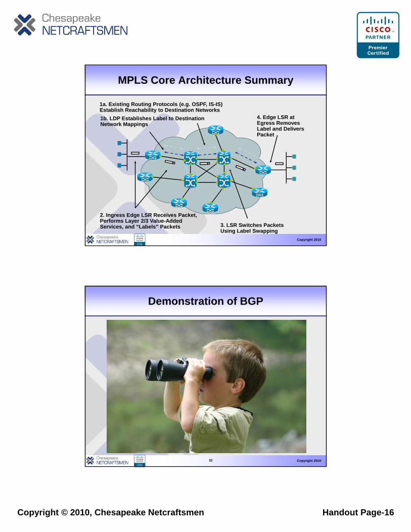
MPLS Core Architecture Summary
1a. Existing Routing Protocols (e.g. OSPF, IS-IS) Establish Reachability to Destination Networks1b. LDP Establishes Label to Destination Network Mappings
4. Edge LSR at Egress Removes Network Mappings gLabel and Delivers Packet
Copyright 2010
2. Ingress Edge LSR Receives Packet, Performs Layer 2/3 Value-Added Services, and “Labels” Packets 3. LSR Switches Packets
Using Label Swapping
Demonstration of BGP
Copyright 201032
Copyright © 2010, Chesapeake Netcraftsmen Handout Page-17
Agenda
• Why Use MPLS?• Label Distribution Protocol
D t ti– Demonstration• Transit Area BGP Considerations
– Penultimate Hop Popping– Demonstration
• VPN Considerations– Demonstration
Copyright 2010
• Multi-VRF Considerations• AToM Considerations• Traffic Engineering Considerations
33
MPLS L3 VPN Overview
• Customer router (CE) has a IP peering connection with PE/edge router in MPLS network
IP routing/forwarding across PE CE link– IP routing/forwarding across PE-CE link• MPLS VPN network responsible for distributing
routing information to remote VPN sites– MPLS VPN part of customer IP routing domain
• MPLS VPNs enable full-mesh, hub-and-spoke, and hybrid connectivity among connected CE sitesMPLS VPN i bl t i MPLS t k l
Copyright 2010
• MPLS VPN service enablement in MPLS networks only requires VPN configuration at edge/PE nodes– Connectivity in core automatically established via BGP
signaling
Copyright © 2010, Chesapeake Netcraftsmen Handout Page-18
MPLS L3 VPN Technology Components
• PE-CE link– Can be any type of Layer-2 connection (e.g., FR, Ethernet)
CE configured to route IP traffic to/from adjacent PE router– CE configured to route IP traffic to/from adjacent PE router– Variety of routing options; static routes, eBGP, OSPF, IS-IS
• MPLS L3VPN Control Plane– Separation of customer routing via virtual VPN routing table– In PE router: customer I/Fs connected to virtual routing table– Between PE routers: customer routes exchanged via BGP
• MPLS L3VPN Forwarding Plane
Copyright 2010
• MPLS L3VPN Forwarding Plane– Separation of customer VPN traffic via additional VPN label– VPN label used by receiving PE to identify VPN routing table
MPLS VPN Benefits for the Enterprise
• Enables site/campus network segmentation– Allows for dedicated connectivity for users,
applications etcapplications, etc.– Leverage same network for multiple services and
organizations• Enables easier setup of WAN connectivity
– Easier configuration of site-to-site WAN connectivity (for L3VPN and VPLS); only one WAN connection needed
Copyright 2010
Copyright © 2010, Chesapeake Netcraftsmen Handout Page-19
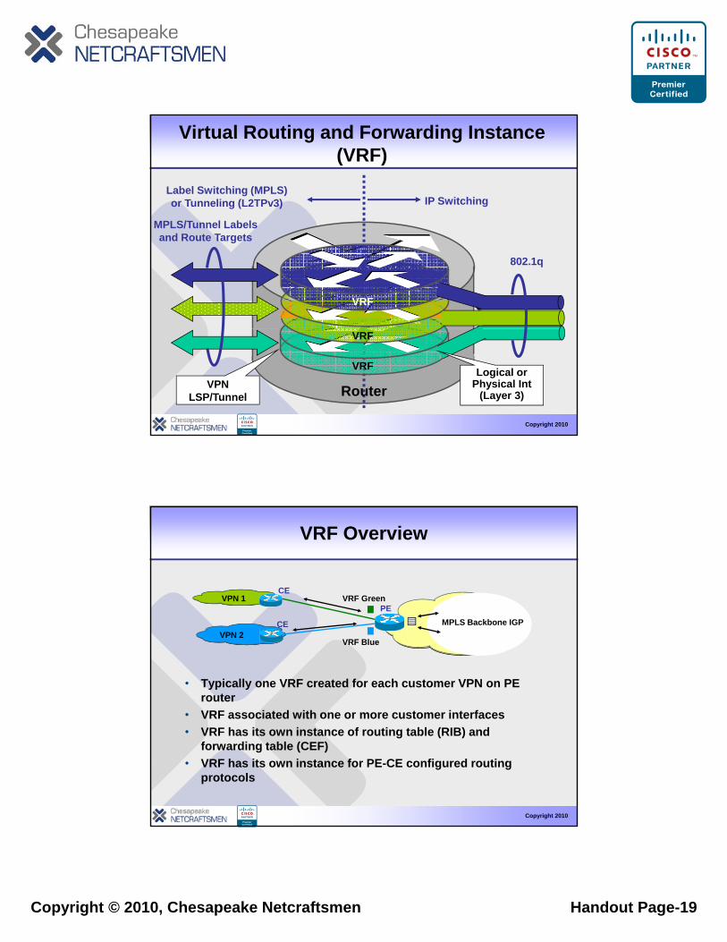
Virtual Routing and Forwarding Instance (VRF)
MPLS/T l L b l
IP SwitchingLabel Switching (MPLS) or Tunneling (L2TPv3)
802.1q
VRF
MPLS/Tunnel Labelsand Route Targets
Copyright 2010
VRF
VRF
VPN LSP/Tunnel
Logical or Physical Int
(Layer 3)Router
VRF Overview
VRF GreenCE
PEVPN 1
• Typically one VRF created for each customer VPN on PE router
• VRF associated with one or more customer interfaces
VRF Blue
CEVPN 2
MPLS Backbone IGP
Copyright 2010
• VRF has its own instance of routing table (RIB) and forwarding table (CEF)
• VRF has its own instance for PE-CE configured routing protocols
Copyright © 2010, Chesapeake Netcraftsmen Handout Page-20
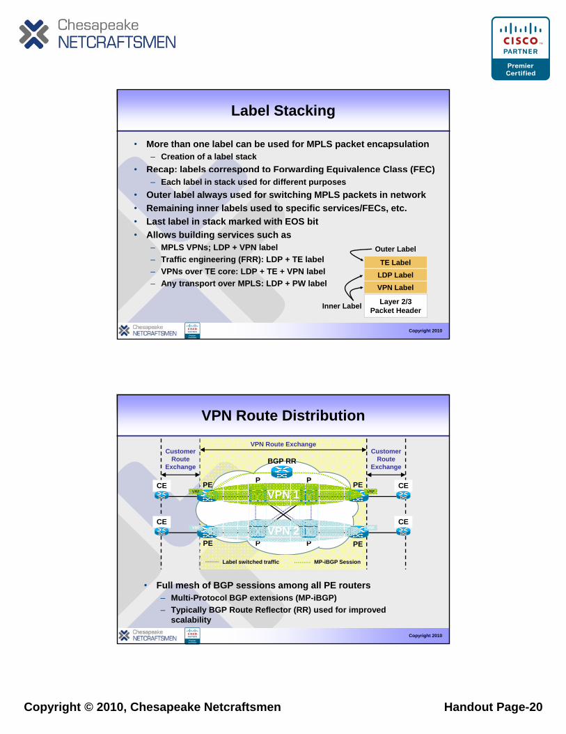
Label Stacking
• More than one label can be used for MPLS packet encapsulation– Creation of a label stack
• Recap: labels correspond to Forwarding Equivalence Class (FEC)p p g q C ( C)– Each label in stack used for different purposes
• Outer label always used for switching MPLS packets in network• Remaining inner labels used to specific services/FECs, etc.• Last label in stack marked with EOS bit• Allows building services such as
– MPLS VPNs; LDP + VPN label Outer Label
Copyright 2010
– Traffic engineering (FRR): LDP + TE label– VPNs over TE core: LDP + TE + VPN label– Any transport over MPLS: LDP + PW label
TE LabelLDP LabelVPN Label
Inner Label Layer 2/3Packet Header
VPN Route Distribution
PP
CustomerRoute
Exchange
CustomerRoute
Exchange
VPN Route Exchange
BGP RR
Label switched traffic
P
P
P
P
PE
PE PE
PECE
CE
CE
CEVRF VRFVPN 2
VRF VRFVPN 1
MP iBGP Session
Copyright 2010
• Full mesh of BGP sessions among all PE routers– Multi-Protocol BGP extensions (MP-iBGP)– Typically BGP Route Reflector (RR) used for improved
scalability
Label switched traffic MP-iBGP Session
Copyright © 2010, Chesapeake Netcraftsmen Handout Page-21
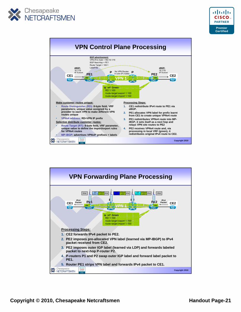
VPN Control Plane Processing
PPPE1 PE2No VPN Routes in core (P) nodes
eBGP:16.1/16 IP Subnet
BGP advertisement:VPN-IPv4 Addr = RD:16.1/16BGP Next-Hop = PE1Route Target = 100:1Label=42 eBGP:
16.1/16 IP Subnet
Make customer routes unique:• Route Distinguisher (RD): 8-byte field, VRF
parameters; unique value assigned by a
Processing Steps:1. CE1 redistribute IPv4 route to PE1 via
eBGP
PE1 PE2CE1 CE2
ip vrf GreenRD 1:100route-target export 1:100route-target import 1:100
in core (P) nodes
VRF VRFVPN 1
Copyright 2010
parameters; unique value assigned by a provider to each VPN to make different VPN routes unique
• VPNv4 address: RD+VPN IP prefix Selective distribute customer routes:• Route Target (RT): 8-byte field, VRF parameter,
unique value to define the import/export rules for VPNv4 routes
• MP-iBGP: advertises VPNv4* prefixes + labels
eBGP.2. PE1 allocates VPN label for prefix learnt
from CE1 to create unique VPNv4 route3. PE1 redistributes VPNv4 route into MP-
iBGP, it sets itself as a next hop and relays VPN site routes to PE2
4. PE2 receives VPNv4 route and, via processing in local VRF (green), it redistributes original IPv4 route to CE2.
VPN Forwarding Plane Processing
P2P1PE1 PE2CE1 CE2IPv4
PacketIPv4
Packet
IPv4IPv4VPNv4Label
IGPLabel AIPv4VPNv4
LabelIGP
Label BIPv4VPNv4Label
IGPLabel CIPv4
Processing Steps:1. CE2 forwards IPv4 packet to PE2.2 PE2 imposes pre allocated VPN label (learned ia MP IBGP) to IP 4
CE1 CE2
ip vrf GreenRD 1:100route-target export 1:100route-target import 1:100
PacketVRF VRFVPN 1
Packet
Copyright 2010
2. PE2 imposes pre-allocated VPN label (learned via MP-IBGP) to IPv4 packet received from CE2.
3. PE2 imposes outer IGP label (learned via LDP) and forwards labeled packet to next-hop P-router P2.
4. P-routers P1 and P2 swap outer IGP label and forward label packet to PE1.
5. Router PE1 strips VPN label and forwards IPv4 packet to CE1.
Copyright © 2010, Chesapeake Netcraftsmen Handout Page-22
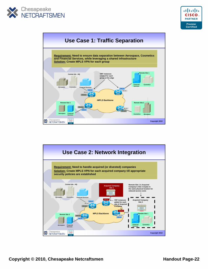
Use Case 1: Traffic Separation
Requirement: Need to ensure data separation between Aerospace, Cosmetics and Financial Services, while leveraging a shared infrastructureSolution: Create MPLS VPN for each group
Aerospace Cosmetics Financial Services
Central site - HQ
CosmeticsFinancial Services
Remote Site 1
VPN_FinVPN_Fin
VPN_CosVPN_Cos
VRF instances created for each group at the edge
Copyright 2010
AerospaceCosmetics
Remote Site 2
Aerospace Financial Services
Remote Site 3
VPN_FinVPN_Cos
•VPN_Aero
•VPN_Aero
VPN_Aero
•MPLS Backbone
Use Case 2: Network Integration
Requirement: Need to handle acquired (or divested) companiesSolution: Create MPLS VPN for each acquired company till appropriate security policies are establishedsecurity policies are established
VPN_Fin
VPN_Cos
Acquired Company Site 2
Acquired Company Site 1
VRF instances added for each site of Acquired C
VPN_Acq
Remote Site 1 & Acquired Company’s Site 2 maybe in the same physical location for reduced access costs
Aerospace Cosmetics Financial Services
Central site - HQ
Copyright 2010
CosmeticsFinancial Services
Remote Site 1
Aerospace Financial Services
Remote Site 2
VPN_Aero
VPN_Fin
VPN_Aero
VPN_Fin
VPN_CosMPLS Backbone
VPN_Acq
Company
Copyright © 2010, Chesapeake Netcraftsmen Handout Page-23
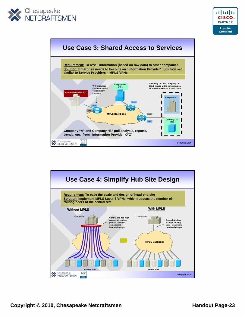
Use Case 3: Shared Access to Services
Requirement: To resell information (based on raw data) to other companiesSolution: Enterprise needs to become an “Information Provider”. Solution set similar to Service Providers – MPLS VPNs
“Information Provider XYZ”
Company “A”Site 1
Company “B”
VPN_A
VPN_A
VPN B
VRF instances created for each “subscriber” company
Company “B” and Company “A” Site 2 maybe in the same physical location for reduced access costs
Copyright 2010
Company “A” Site 2VPN_A
VPN_B
VPN_BMPLS Backbone
Company “A” and Company “B” pull analysis, reports, trends, etc. from “Information Provider XYZ”
Use Case 4: Simplify Hub Site Design
Requirement: To ease the scale and design of head-end siteSolution: Implement MPLS Layer 3 VPNs, which reduces the number of routing peers of the central site
Without MPLSWithout MPLS
Central SiteCentral site has high number of routing peers – creates a complicated headend design
With MPLSWith MPLS
Central Site
Central site has a single routing peer – enhancing head-end design
MPLS Backbone
Copyright 2010
•Remote Sites Remote Sites
MPLS Backbone
Copyright © 2010, Chesapeake Netcraftsmen Handout Page-24
Demonstration of VPNs
Copyright 201047
Agenda
• Why Use MPLS?• Label Distribution Protocol
D t ti– Demonstration• Transit Area BGP Considerations
– Penultimate Hop Popping– Demonstration
• VPN Considerations– Demonstration
Copyright 2010
• Multi-VRF Considerations• AToM Considerations• Traffic Engineering Considerations
48
Copyright © 2010, Chesapeake Netcraftsmen Handout Page-25
VPN-ACECE
MP-iBGP
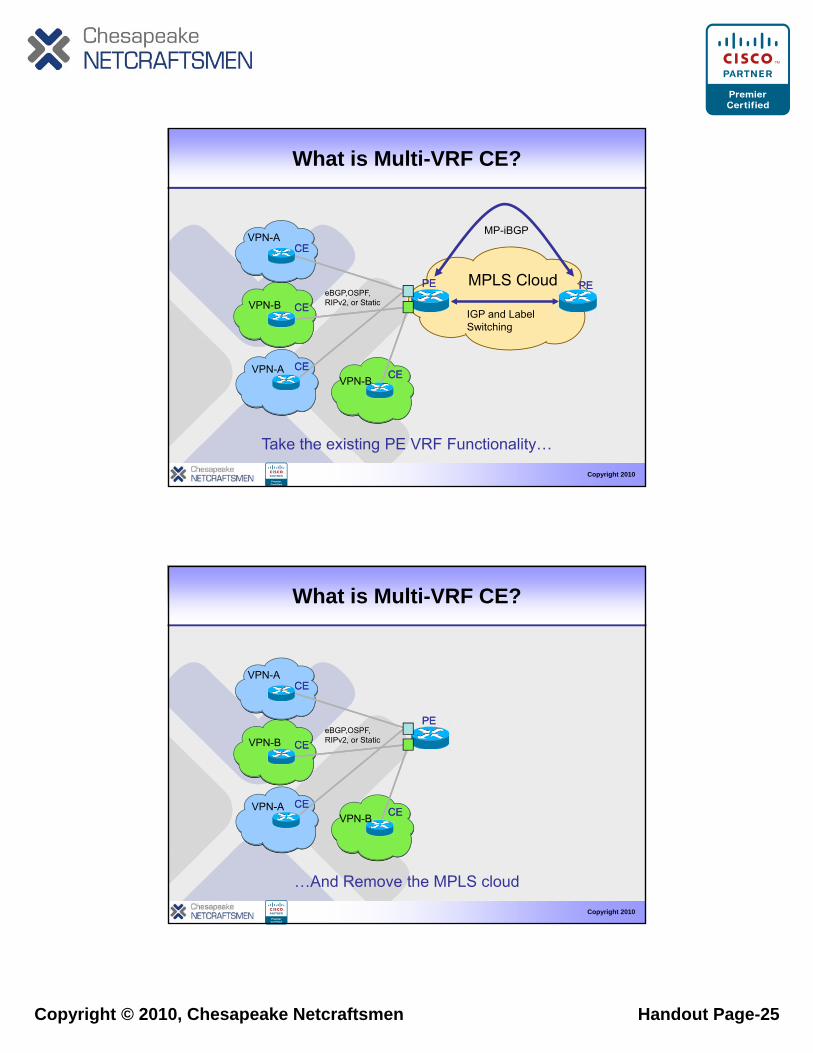
What is Multi-VRF CE?
PEPE
CECEVPN-B
CECE
CECE
IGP and Label Switching
PEPE
VPN A
MPLS CloudeBGP,OSPF,RIPv2, or Static
Copyright 2010
CECE
Take the existing PE VRF Functionality…
CECEVPN-BVPN-A
VPN-ACECE
What is Multi-VRF CE?
PEPE
CECEVPN-B
CECE
CECE
VPN A
eBGP,OSPF,RIPv2, or Static
Copyright 2010
CECE
…And Remove the MPLS cloud
CECEVPN-BVPN-A
Copyright © 2010, Chesapeake Netcraftsmen Handout Page-26
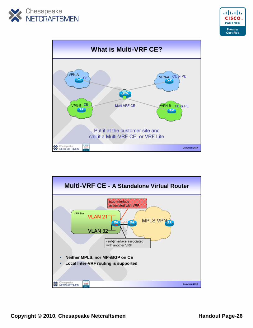
What is Multi-VRF CE?
VPN-A CE or PECE or PECECE VPN A
Multi VRF CEMulti VRF CECECEVPN-B
CE or PECE or PECECE
CE or PECE or PE•VPN-B
VPN-A
Copyright 2010
…Put it at the customer site and call it a Multi-VRF CE, or VRF Lite
Multi-VRF CE - A Standalone Virtual Router
VPN Site
(sub)interface associated with VRF
PE
VPN Site
(sub)interface associated with another VRF
CE
VLAN 32VLAN 32
VLAN 21VLAN 21MPLS VPNMPLS VPN
Copyright 2010
• Neither MPLS, nor MP-iBGP on CE• Local Inter-VRF routing is supported
Copyright © 2010, Chesapeake Netcraftsmen Handout Page-27
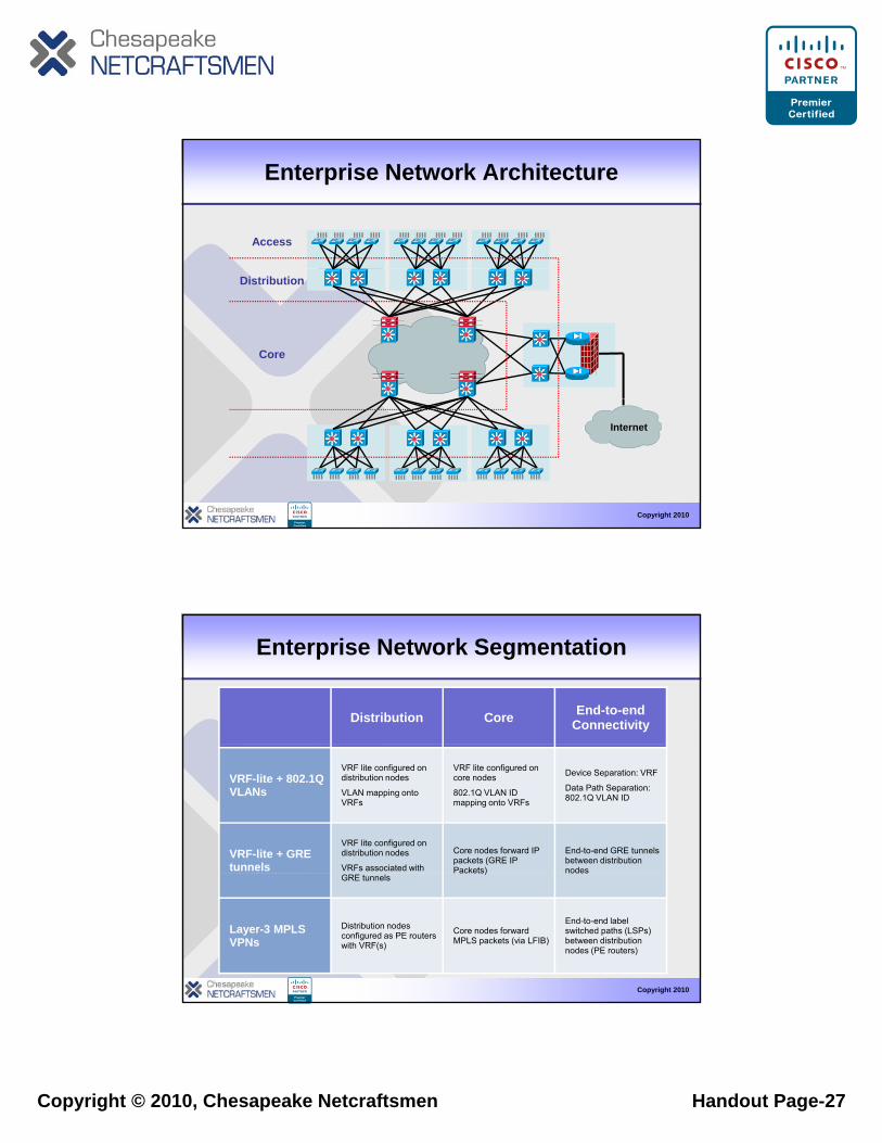
Enterprise Network Architecture
Access
Distribution
Core
Copyright 2010
Internet
Enterprise Network Segmentation
Distribution Core End-to-end Connectivity
VRF-lite + 802.1Q VLANs
VRF lite configured on distribution nodes
VLAN mapping onto VRFs
VRF lite configured on core nodes
802.1Q VLAN ID mapping onto VRFs
Device Separation: VRF
Data Path Separation: 802.1Q VLAN ID
VRF-lite + GRE tunnels
VRF lite configured on distribution nodes
VRFs associated with
Core nodes forward IP packets (GRE IP Packets)
End-to-end GRE tunnels between distribution nodes
Copyright 2010
GRE tunnels)
Layer-3 MPLS VPNs
Distribution nodes configured as PE routers with VRF(s)
Core nodes forward MPLS packets (via LFIB)
End-to-end label switched paths (LSPs) between distribution nodes (PE routers)
Copyright © 2010, Chesapeake Netcraftsmen Handout Page-28
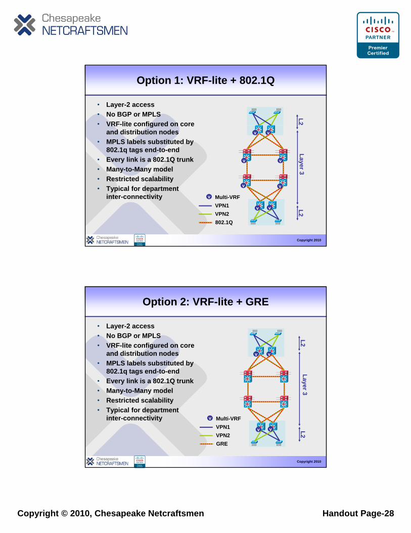
Option 1: VRF-lite + 802.1Q
L2• Layer-2 access• No BGP or MPLS• VRF-lite configured on core
vv
Layer 3
v
v
v
v
VRF lite configured on core and distribution nodes
• MPLS labels substituted by 802.1q tags end-to-end
• Every link is a 802.1Q trunk• Many-to-Many model• Restricted scalability
Copyright 2010
v v
v
L2
v v
802.1Q
Multi-VRFVPN1VPN2
• Typical for department inter-connectivity
Option 2: VRF-lite + GRE
L2
• Layer-2 access• No BGP or MPLS• VRF-lite configured on core
vv
Layer 3
VRF lite configured on core and distribution nodes
• MPLS labels substituted by 802.1q tags end-to-end
• Every link is a 802.1Q trunk• Many-to-Many model• Restricted scalability
Copyright 2010
v v
v
L2
GRE
Multi-VRFVPN1VPN2
• Typical for department inter-connectivity
Copyright © 2010, Chesapeake Netcraftsmen Handout Page-29
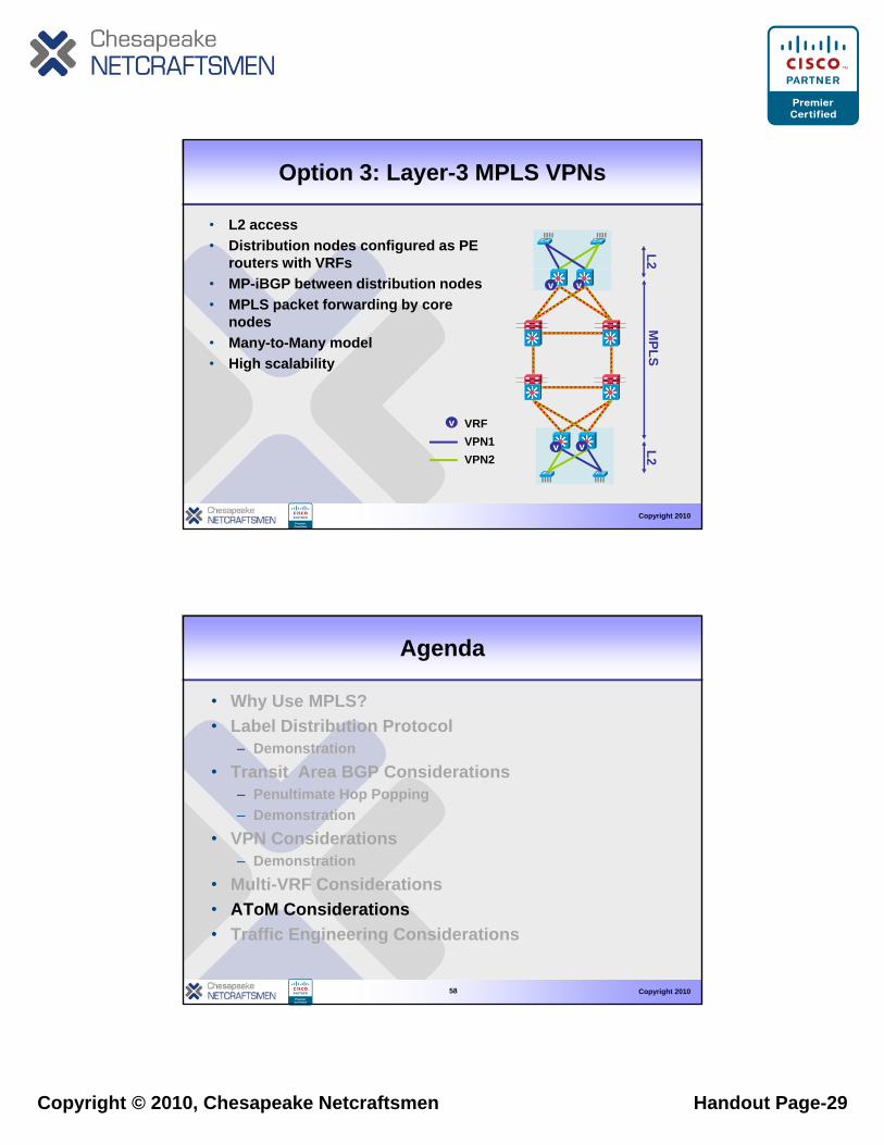
Option 3: Layer-3 MPLS VPNs
• L2 access• Distribution nodes configured as PE
routers with VRFs
L2
• MP-iBGP between distribution nodes• MPLS packet forwarding by core
nodes• Many-to-Many model• High scalability
vv
MPLS
Copyright 2010
v v
v
L2
VRFVPN1VPN2
Agenda
• Why Use MPLS?• Label Distribution Protocol
D t ti– Demonstration• Transit Area BGP Considerations
– Penultimate Hop Popping– Demonstration
• VPN Considerations– Demonstration
Copyright 2010
• Multi-VRF Considerations• AToM Considerations• Traffic Engineering Considerations
58
Copyright © 2010, Chesapeake Netcraftsmen Handout Page-30
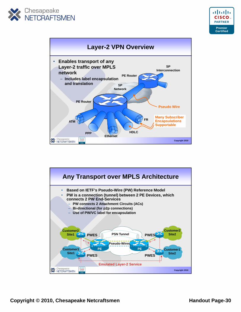
Layer-2 VPN Overview
• Enables transport of any Layer-2 traffic over MPLS network
SP Interconnectionnetwork
– Includes label encapsulation and translation
Pseudo Wire
SP Network
PE Router
PE Router
Copyright 2010
Ethernet
ATM
HDLCPPP
FRMany Subscriber Encapsulations Supportable
Any Transport over MPLS Architecture
• Based on IETF’s Pseudo-Wire (PW) Reference Model• PW is a connection (tunnel) between 2 PE Devices, which
connects 2 PW End-ServicesPW t 2 Att h t Ci it (AC )– PW connects 2 Attachment Circuits (ACs)
– Bi-directional (for p2p connections)– Use of PW/VC label for encapsulation
PSN TunnelPWES PWESCustomer2
Site1Customer2
Site2
Copyright 2010
Pseudo-Wires
Emulated Layer-2 Service
PWES PWES
Customer1 Site1
Customer1 Site2
PEPE
Copyright © 2010, Chesapeake Netcraftsmen Handout Page-31
AToM Technology Components
• PE-CE link– Referred to as Attachment Circuit (AC)– Can be any type of layer-2 connection (e.g., FR, Ethernet)
AT M C t l Pl• AToM Control Plane– Targeted LDP (Label Distribution Protocol) Session– Virtual Connection (VC)-label negotiation, withdrawal, error
notification• AToM Forwarding Plane
– 2 labels used for encapsulation + control word– Outer tunnel (LDP) label
• To get from ingress to egress PE using MPLS LSP
Copyright 2010
– Inner de-multiplexer (VC) label• To identify L2 circuit (packet) encapsulated within tunnel
label– Control word
• Replaces layer-2 header at ingress; used to rebuild layer-2 header at egress
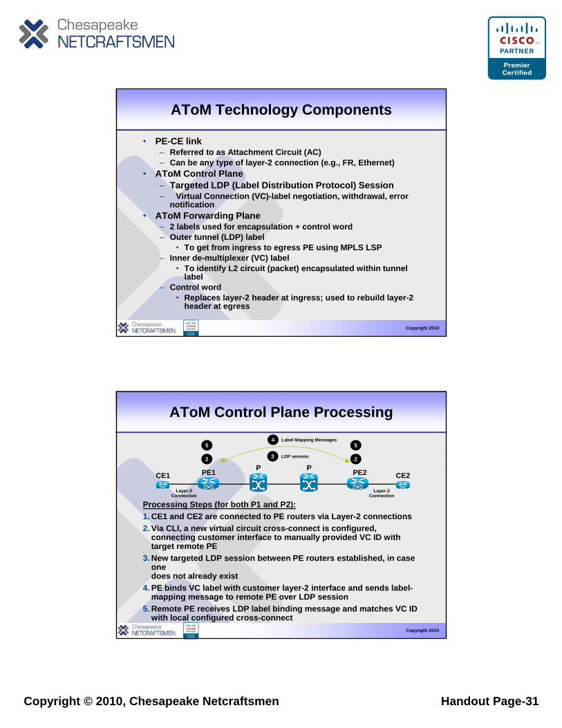
AToM Control Plane Processing
PPPE1 PE2CE1 CE2
3 LDP session
4 Label Mapping Messages
2 2
55
Processing Steps (for both P1 and P2):1. CE1 and CE2 are connected to PE routers via Layer-2 connections2. Via CLI, a new virtual circuit cross-connect is configured,
connecting customer interface to manually provided VC ID with target remote PE
3 N t t d LDP i b t PE t t bli h d i
PE1 PE2CE1 CE2
Layer-2Connection
Layer-2Connection
Copyright 2010
3. New targeted LDP session between PE routers established, in case one does not already exist
4. PE binds VC label with customer layer-2 interface and sends label-mapping message to remote PE over LDP session
5. Remote PE receives LDP label binding message and matches VC ID with local configured cross-connect
Copyright © 2010, Chesapeake Netcraftsmen Handout Page-32
AToM Forwarding Plane Processing
P2P1PE1 PE2CE1 CE2Layer-2Packet
Layer-2Packet
L2L2VCLabel
TunnelLabel AL2VC
LabelTunnelLabel BL2VC
LabelTunnelLabel CL2
Processing Steps:1. CE2 forwards Layer-2 packet to PE2.2. PE2 imposes VC (inner) label to layer-2 packet received from
CE2 and optionally a control word as well (not shown).3. PE2 imposes Tunnel outer label and forwards packet to P2.
CE1 CE2
Copyright 2010
3. PE2 imposes Tunnel outer label and forwards packet to P2.4. P2 and P1 router forwards packet using outer (tunnel) label.5. Router PE2 strips Tunnel label and, based on VC label,
Layer-2 packet is forwarded to customer interface to CE1, after VC label is removed– In case control word is used, new Layer-2 header is generated first.
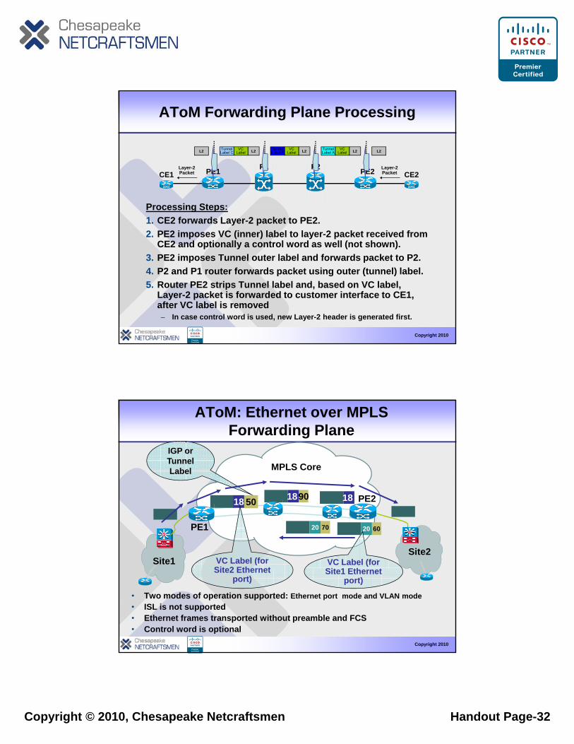
AToM: Ethernet over MPLS Forwarding Plane
MPLS Core
IGP or Tunnel Label
PE1
PE2
Site1
18 50 18 90
20 70 20 60
Site2
18
VC Label (for Site2 Ethernet
VC Label (for Sit 1 Eth t
Copyright 2010
Site2 Ethernet port)
Site1 Ethernet port)
• Two modes of operation supported: Ethernet port mode and VLAN mode• ISL is not supported• Ethernet frames transported without preamble and FCS• Control word is optional
Copyright © 2010, Chesapeake Netcraftsmen Handout Page-33
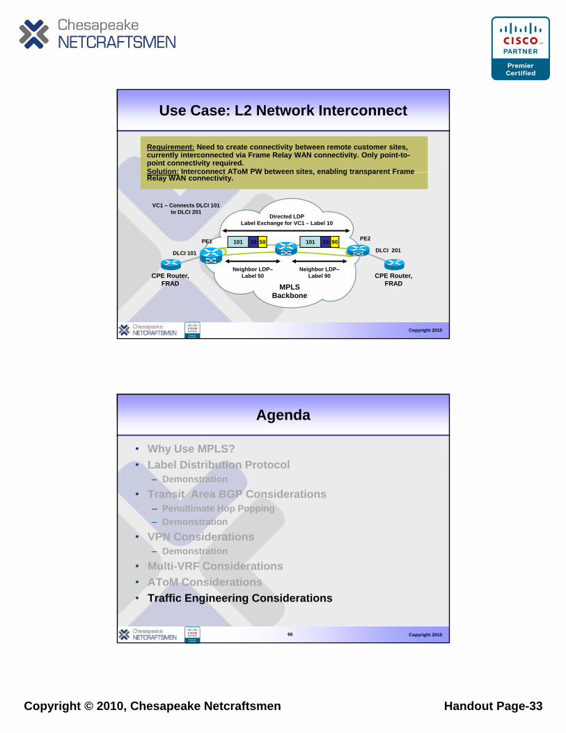
Use Case: L2 Network Interconnect
Requirement: Need to create connectivity between remote customer sites, currently interconnected via Frame Relay WAN connectivity. Only point-to-point connectivity required.Solution: Interconnect AToM PW between sites enabling transparent FrameSolution: Interconnect AToM PW between sites, enabling transparent Frame Relay WAN connectivity.
PE1 PE2
DLCI 101 DLCI 201
Directed LDPLabel Exchange for VC1 – Label 10
101 10 50 101 10 90
VC1 – Connects DLCI 101 to DLCI 201
Copyright 2010
MPLS Backbone
CPE Router, FRAD
Neighbor LDP–Label 50
Neighbor LDP–Label 90 CPE Router,
FRAD
Agenda
• Why Use MPLS?• Label Distribution Protocol
D t ti– Demonstration• Transit Area BGP Considerations
– Penultimate Hop Popping– Demonstration
• VPN Considerations– Demonstration
Copyright 2010
• Multi-VRF Considerations• AToM Considerations• Traffic Engineering Considerations
66
Copyright © 2010, Chesapeake Netcraftsmen Handout Page-34
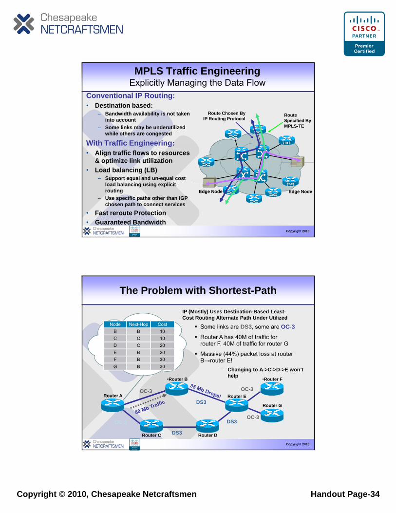
MPLS Traffic Engineering Explicitly Managing the Data Flow
Route Chosen ByIP Routing Protocol
Route Specified By
Conventional IP Routing:• Destination based:
– Bandwidth availability is not taken into account g Specified By
MPLS-TEinto account
– Some links may be underutilized while others are congested
With Traffic Engineering: • Align traffic flows to resources
& optimize link utilization• Load balancing (LB)
– Support equal and un-equal cost
Copyright 2010
Edge Node Edge Node
Support equal and un-equal cost load balancing using explicit routing
– Use specific paths other than IGP chosen path to connect services
• Fast reroute Protection• Guaranteed Bandwidth
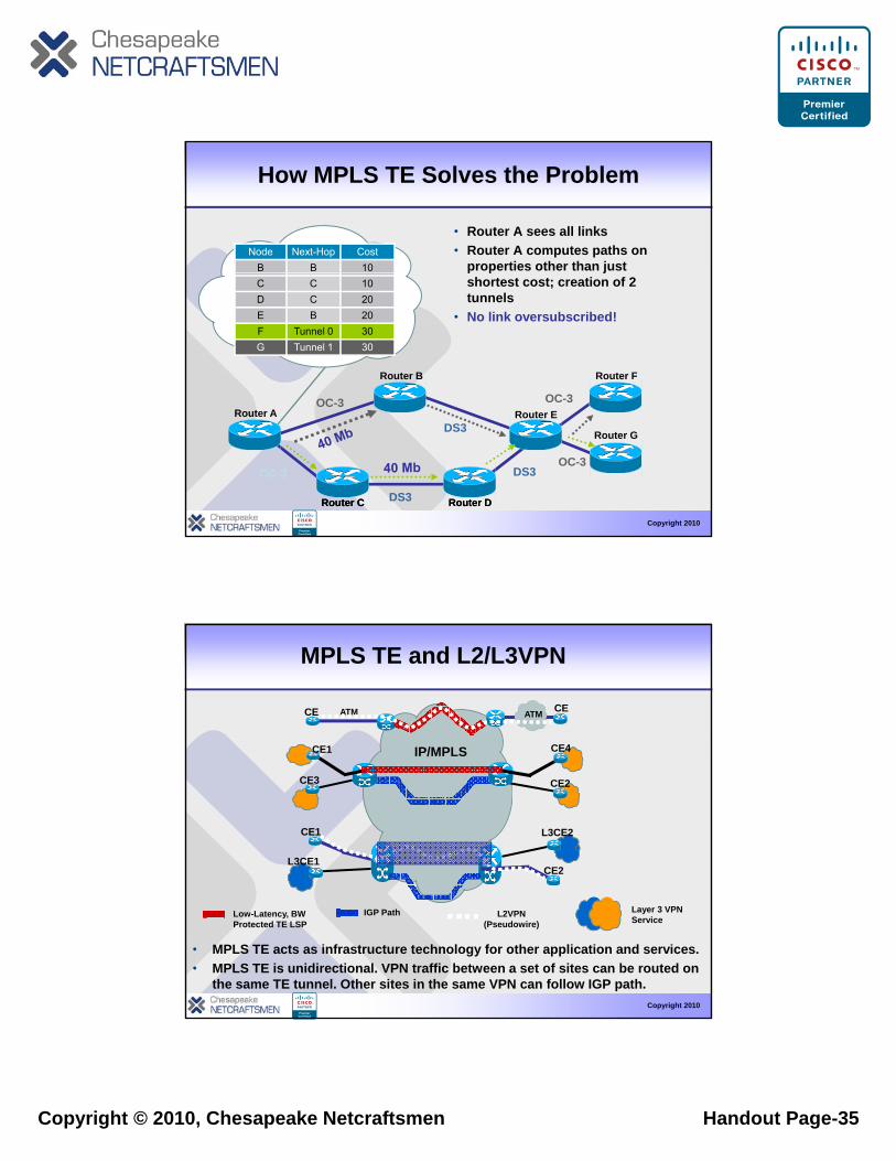
The Problem with Shortest-Path
Some links are DS3, some are OC-3Node Next-Hop CostB B 10
IP (Mostly) Uses Destination-Based Least-Cost Routing Alternate Path Under Utilized
Massive (44%) packet loss at router B→router E!
– Changing to A->C->D->E won’t help
•Router F•Router B
OC-3 OC-3
Router A has 40M of traffic for router F, 40M of traffic for router G
C C 10D C 20E B 20F B 30G B 30
Copyright 2010
Router C Router D
Router AOC 3
OC-3
DS3
DS3
DS3OC-3
Router E
Router G
Copyright © 2010, Chesapeake Netcraftsmen Handout Page-35
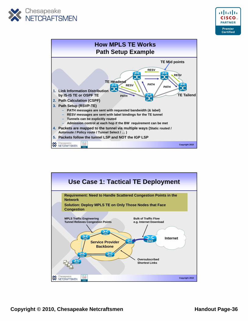
How MPLS TE Solves the Problem
• Router A sees all links• Router A computes paths on
properties other than just Node Next-Hop Cost
B B 10 p p jshortest cost; creation of 2 tunnels
• No link oversubscribed!
OC-3 OC-3
Router FRouter B
C C 10D C 20E B 20F Tunnel 0 30G Tunnel 1 30
Copyright 2010
Router C Router D
OC 3
OC-3
DS3
DS3
DS3OC-3
Router C Router D
Router G
Router A Router E
MPLS TE and L2/L3VPN
IP/MPLS
ATMATMCE CE
CE1 CE4IP/MPLS
CE1 L3CE2
CE2L3CE1
CE3 CE2
Copyright 2010
IGP Path L2VPN (Pseudowire)
Low-Latency, BW Protected TE LSP
Layer 3 VPN Service
• MPLS TE acts as infrastructure technology for other application and services.• MPLS TE is unidirectional. VPN traffic between a set of sites can be routed on
the same TE tunnel. Other sites in the same VPN can follow IGP path.
Copyright © 2010, Chesapeake Netcraftsmen Handout Page-36
How MPLS TE WorksPath Setup Example
RESV
RESV
TE Mid points
TE Headend
TE TailendPATH
PATHPATH
RESV
RESV
1. Link Information Distribution by IS-IS TE or OSPF TE
2. Path Calculation (CSPF)3. Path Setup (RSVP-TE)
– PATH messages are sent with requested bandwidth (& label)
Copyright 2010
g q ( )– RESV messages are sent with label bindings for the TE tunnel– Tunnels can be explicitly routed– Admission control at each hop if the BW requirement can be met
4. Packets are mapped to the tunnel via multiple ways (Static routed / Autoroute / Policy route / Tunnel Select / … )
5. Packets follow the tunnel LSP and NOT the IGP LSP
Use Case 1: Tactical TE Deployment
Requirement: Need to Handle Scattered Congestion Points in the NetworkSolution: Deploy MPLS TE on Only Those Nodes that Face Congestion
Requirement: Need to Handle Scattered Congestion Points in the NetworkSolution: Deploy MPLS TE on Only Those Nodes that Face CongestionCongestionCongestion
InternetService Provider
B kb
Bulk of Traffic Flowe.g. Internet Download
MPLS Traffic Engineering Tunnel Relieves Congestion Points
Copyright 2010
Backbone
Oversubscribed Shortest Links
Copyright © 2010, Chesapeake Netcraftsmen Handout Page-37
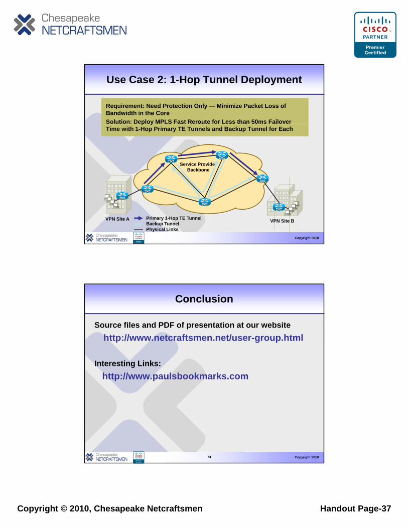
Use Case 2: 1-Hop Tunnel Deployment
Requirement: Need Protection Only — Minimize Packet Loss of Bandwidth in the CoreSolution: Deploy MPLS Fast Reroute for Less than 50ms Failover
Requirement: Need Protection Only — Minimize Packet Loss of Bandwidth in the CoreSolution: Deploy MPLS Fast Reroute for Less than 50ms Failover p yTime with 1-Hop Primary TE Tunnels and Backup Tunnel for Each
p yTime with 1-Hop Primary TE Tunnels and Backup Tunnel for Each
Service ProviderBackbone
Copyright 2010
VPN Site A VPN Site BPrimary 1-Hop TE TunnelBackup TunnelPhysical Links
Conclusion
Source files and PDF of presentation at our websitehttp://www.netcraftsmen.net/user-group.html
Interesting Links:http://www.paulsbookmarks.com
Copyright 201074