about selecting capacity of inverter - sunnice selecting capacity of inverter.pdf · 1. selecting...
TRANSCRIPT
E6581182⑩
Inverter application manual
About Selecting Capacity of Inverter
E6581182
1
-Contents-
1. Selecting the capacity of the inverter ......................................................................................................................................2
1.1 Calculation equations for selecting the capacity of the inverter.........................................................................................2
1.1.1 Calculating acceleration and deceleration times ........................................................................................................3 1.1.2 Selecting braking resistors .........................................................................................................................................5
1.2 Selection procedure for the inverter capacity ....................................................................................................................6
1.2.1 Confirming the load torque and motor capacity ..........................................................................................................6
1.2.2 Confirming the inertia .................................................................................................................................................7
1.2.3 Confirming the acceleration torque.............................................................................................................................8
1.2.4 Confirming the deceleration torque ............................................................................................................................9 1.2.5 In case of the short-time acceleration/deceleration or starting torque of 150 % or more.......................................... 11
1.2.6 Calculation of the minimum acceleration/deceleration times....................................................................................12
1.2.7 Selecting the inverter................................................................................................................................................13
1.3 Example of calculating the capacity (fans) ......................................................................................................................14
2. Selecting the capacity of motor.............................................................................................................................................16
2.1 Formulas for motor..........................................................................................................................................................16 2.2 J equations......................................................................................................................................................................17
2.3 Equations of kW necessary for motor .............................................................................................................................18
2.4 Other equations concerning motor ..................................................................................................................................20
2.5 Equation for capacity of adjustable speed motor.............................................................................................................20
Appendix 1: List of motor data....................................................................................................................................................23
Appendix 2: List of braking resistors...........................................................................................................................................27 Appendix 3: List of minimum allowable resistances ...................................................................................................................29
E6581182
2
1. Selecting the capacity of the inverter
To drive a motor by the inverter, it should be important to select a proper capacity of a motor before selecting the
capacity of the inverter.
When selecting the capacity of the inverter, each of items below will be converted into a numerical value to judge
validity.
Sufficient starting torque can be obtained?
Acceleration can be attained within a specified time of period?
Deceleration can be attained within a specified time of period?
1.1 Calculation equations for selecting the capacity of the inverter
The inertia at motor shaft J (GD2) is required to calculate the capacity of the inverter. Note)
Use J (GD2) to obtain necessary acceleration torque, steady-state torque, and deceleration torque.
In paragraph 1.1.1, select the inverter for the specified capacity of a motor and obtain minimum acceleration and
deceleration times.
In paragraph 1.1.2, calculate a braking resistance capacity to shorten the deceleration time.
Matters to be attended:
When a three-phase induction motor is driven through commercial power supply, it is generally possible to output
the starting torque at approximately 300% of the torque. In the inverter with the same capacity as above, however,
it generally output the starting torque at 150 to 200 % of the torque for protection of a machine. Therefore, the
applications below may require the capacity of the inverter or the capacities of both the inverter and motor to be
increased.
In the case that the starting torque 150% or more is required based on the motor selected
In the case that the starting current exceeds the rated current of overload protection of the inverter
(for example, 150% for 1 minutes and 165% for 2 seconds for VFAS1).
In the case that an excessive short time is required for acceleration
Note): Use only either of SI system of units and MKS system of units for calculation.
Table 1. Conversion ratio of systems of units Items SI system of units MKS system of units
Rotating speed Rotating speed (min-1) Rotating speed (rpm) Torque 9.8 (N・m)
[SI system of units = 9.8 MKS system of units]
1 (kgf・m)
Inertia J=1/4GD2 (kg・m2) GD2 (kgf・m2)
E6581182
3
1.1.1 Calculating acceleration and deceleration times
a) Acceleration time
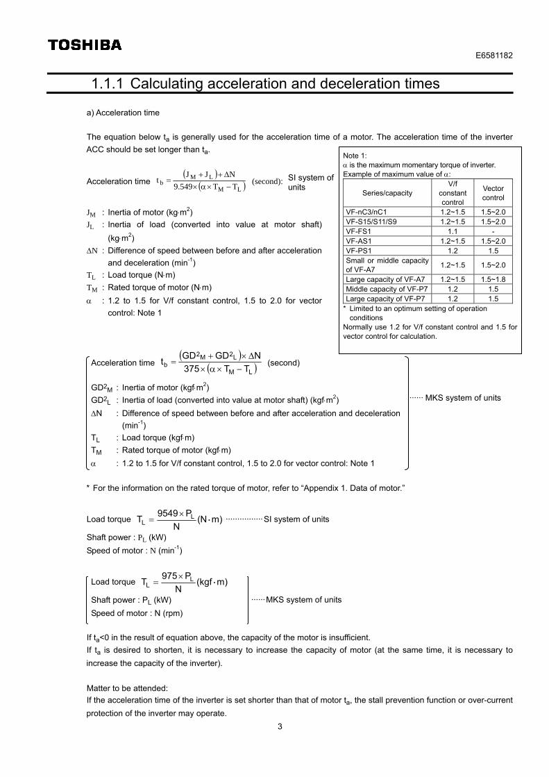
The equation below ta is generally used for the acceleration time of a motor. The acceleration time of the inverter
ACC should be set longer than ta.
Acceleration time
LM
LMb TT9.549
NJJt
(second):
JM : Inertia of motor (kgm2)
JL : Inertia of load (converted into value at motor shaft)
(kgm2)
N : Difference of speed between before and after acceleration
and deceleration (min-1)
TL : Load torque (Nm)
TM : Rated torque of motor (Nm)
: 1.2 to 1.5 for V/f constant control, 1.5 to 2.0 for vector
control: Note 1
Acceleration time
LM
L2M2
b TT375
NGDGDt
(second)
GD2M : Inertia of motor (kgfm2)
GD2L : Inertia of load (converted into value at motor shaft) (kgfm2)
N : Difference of speed between before and after acceleration and deceleration
(min-1)
TL : Load torque (kgfm)
TM : Rated torque of motor (kgfm)
: 1.2 to 1.5 for V/f constant control, 1.5 to 2.0 for vector control: Note 1
* For the information on the rated torque of motor, refer to “Appendix 1. Data of motor.”
Load torque )mN(N
P9549T L
L ・
················SI system of units
Shaft power : PL (kW)
Speed of motor : N (min-1)
Load torque )mkgf(N
P975T L
L ・
Shaft power : PL (kW)
Speed of motor : N (rpm)
If ta<0 in the result of equation above, the capacity of the motor is insufficient.
If ta is desired to shorten, it is necessary to increase the capacity of motor (at the same time, it is necessary to
increase the capacity of the inverter).
Matter to be attended:
If the acceleration time of the inverter is set shorter than that of motor ta, the stall prevention function or over-current
protection of the inverter may operate.
Note 1: is the maximum momentary torque of inverter. Example of maximum value of :
Series/capacity V/f
constant control
Vector control
VF-nC3/nC1 1.2~1.5 1.5~2.0VF-S15/S11/S9 1.2~1.5 1.5~2.0VF-FS1 1.1 - VF-AS1 1.2~1.5 1.5~2.0VF-PS1 1.2 1.5 Small or middle capacity of VF-A7
1.2~1.5 1.5~2.0
Large capacity of VF-A7 1.2~1.5 1.5~1.8Middle capacity of VF-P7 1.2 1.5 Large capacity of VF-P7 1.2 1.5
* Limited to an optimum setting of operation conditions
Normally use 1.2 for V/f constant control and 1.5 for vector control for calculation.
······ MKS system of units
······MKS system of units
SI system of units
E6581182
4
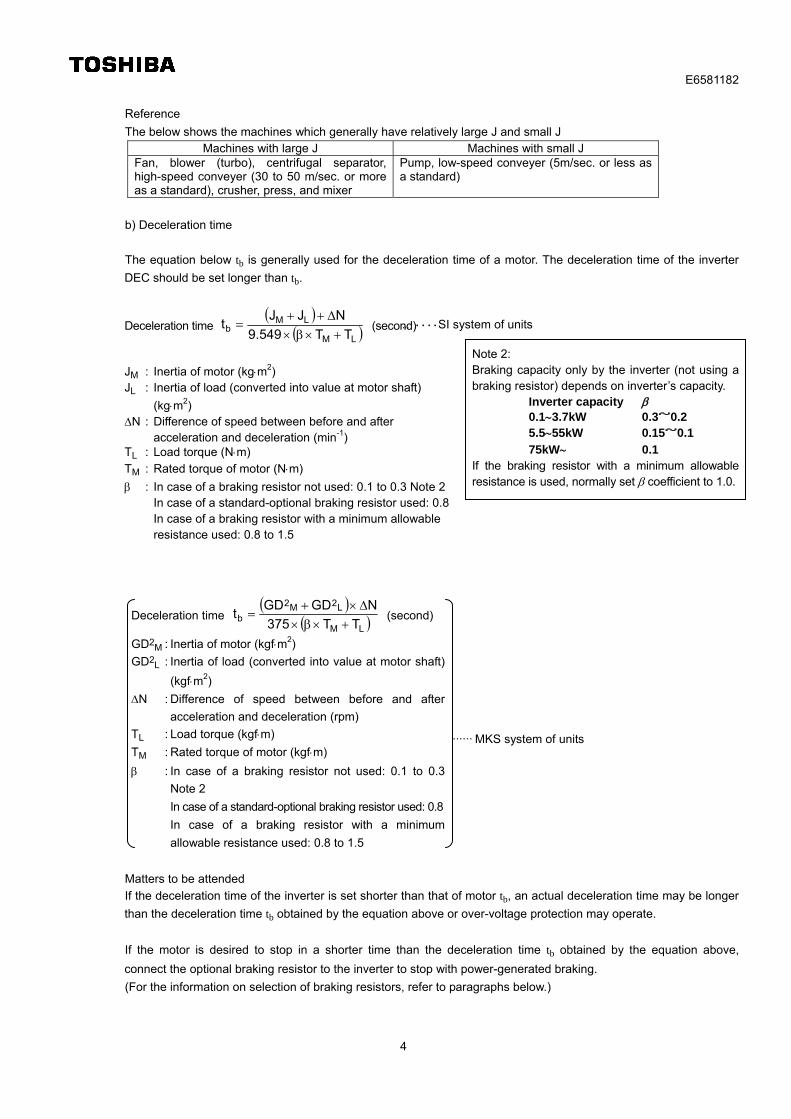
Reference
The below shows the machines which generally have relatively large J and small J Machines with large J Machines with small J
Fan, blower (turbo), centrifugal separator, high-speed conveyer (30 to 50 m/sec. or more as a standard), crusher, press, and mixer
Pump, low-speed conveyer (5m/sec. or less as a standard)
b) Deceleration time
The equation below tb is generally used for the deceleration time of a motor. The deceleration time of the inverter
DEC should be set longer than tb.
Deceleration time
LM
LMb TT9.549
NJJt
(second)
JM : Inertia of motor (kgm2) JL : Inertia of load (converted into value at motor shaft)
(kgm2) N : Difference of speed between before and after
acceleration and deceleration (min-1) TL : Load torque (Nm) TM : Rated torque of motor (Nm)
: In case of a braking resistor not used: 0.1 to 0.3 Note 2 In case of a standard-optional braking resistor used: 0.8 In case of a braking resistor with a minimum allowable resistance used: 0.8 to 1.5
Deceleration time
LM
L2M2
b TT375
NGDGDt
(second)
GD2M : Inertia of motor (kgfm2)
GD2L : Inertia of load (converted into value at motor shaft)
(kgfm2)
N : Difference of speed between before and after
acceleration and deceleration (rpm)
TL : Load torque (kgfm)
TM : Rated torque of motor (kgfm)
: In case of a braking resistor not used: 0.1 to 0.3
Note 2
In case of a standard-optional braking resistor used: 0.8
In case of a braking resistor with a minimum
allowable resistance used: 0.8 to 1.5
Matters to be attended
If the deceleration time of the inverter is set shorter than that of motor tb, an actual deceleration time may be longer
than the deceleration time tb obtained by the equation above or over-voltage protection may operate.
If the motor is desired to stop in a shorter time than the deceleration time tb obtained by the equation above,
connect the optional braking resistor to the inverter to stop with power-generated braking.
(For the information on selection of braking resistors, refer to paragraphs below.)
Note 2: Braking capacity only by the inverter (not using a braking resistor) depends on inverter’s capacity.
Inverter capacity 0.13.7kW 0.3~0.2 5.555kW 0.15~0.1
75kW 0.1 If the braking resistor with a minimum allowable resistance is used, normally set coefficient to 1.0.
…・・・・SI system of units
······ MKS system of units
E6581182
5
1.1.2 Selecting braking resistors
When a large deceleration torque is required because of large inertia of load, the braking unit/braking resistor unit
can be used to radiate regenerative energy.
The braking torque when using a standard optional braking resistor is approximate 80% of the rated torque.
The braking torque when using a braking resistor with a minimum allowable resistance is 80 to 150% of the rated
torque (see appendix 4).
* In case of the braking resistor not used:
Inverter capacity braking torque
0.13.7kW 30%20%
5.555kW 15%10%
75kW 10%
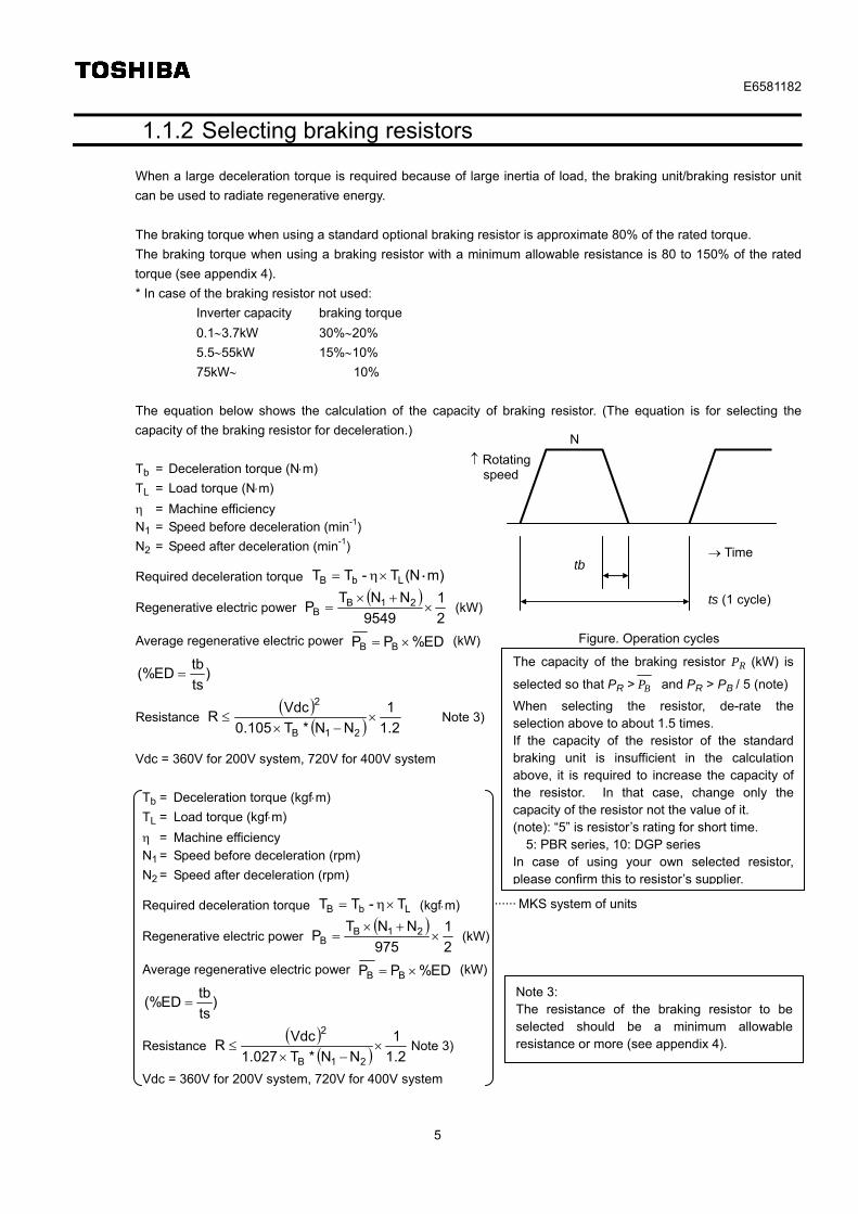
The equation below shows the calculation of the capacity of braking resistor. (The equation is for selecting the
capacity of the braking resistor for deceleration.)
Tb = Deceleration torque (Nm)
TL = Load torque (Nm)
= Machine efficiency N1 = Speed before deceleration (min-1)
N2 = Speed after deceleration (min-1) Required deceleration torque )mN(T-TT LbB ・
Regenerative electric power
2
1
9549
NNTP 21B
B
(kW)
Average regenerative electric power ED%PP BB (kW)
)ts
tbED(%
Resistance
2.1
1
NN*T105.0
VdcR
21B
2
Note 3)
Vdc = 360V for 200V system, 720V for 400V system
Tb = Deceleration torque (kgfm)
TL = Load torque (kgfm)
= Machine efficiency N1 = Speed before deceleration (rpm)
N2 = Speed after deceleration (rpm) Required deceleration torque LbB T-TT (kgfm)
Regenerative electric power
2
1
975
NNTP 21B
B
(kW)
Average regenerative electric power ED%PP BB (kW)
)ts
tbED(%
Resistance
2.1
1
NN*T027.1
VdcR
21B
2
Note 3)
Vdc = 360V for 200V system, 720V for 400V system
ts (1 cycle)
tb Time
Rotating speed
N
Figure. Operation cycles
······ MKS system of units
The capacity of the braking resistor PR (kW) is
selected so that PR > BP and PR > PB / 5 (note)
When selecting the resistor, de-rate the selection above to about 1.5 times. If the capacity of the resistor of the standard braking unit is insufficient in the calculation above, it is required to increase the capacity of the resistor. In that case, change only the capacity of the resistor not the value of it. (note): “5” is resistor’s rating for short time. 5: PBR series, 10: DGP series In case of using your own selected resistor, please confirm this to resistor’s supplier.
Note 3: The resistance of the braking resistor to be selected should be a minimum allowable resistance or more (see appendix 4).

E6581182
6
1.2 Selection procedure for the inverter capacity
When selecting the inverter capacity, follow the procedure below to confirm that each value satisfies the
specifications of the motor and inverter applicable.
Items to be calculated:
a. Load torque
b. Inertia
c. Acceleration torque
d. Deceleration torque (Selecting the braking resistor: paragraph 1.1.2)
1.2.1 Confirming the load torque and motor capacity
Temporarily select the motor capacity using a load torque.
(If the motor capacity has been decided, confirm the rated torque of motor > load torque converted into a value at a
motor shaft.
Load torque at a motor shaft N
P9549T M
L
(Nm)······································ SI system of units
Temporarily selected motor capacity 9549
NTP L
M
(kW)
PM : Rated output of motor (kW)
N : Rated speed of motor (min-1)
TL : Load torqueM
L
N
N (Nm)
NL : Speed at load side
NM : Speed at motor side
Load torque at a motor shaft N
P975T M
L
(kgfm)
Temporarily selected motor capacity 975
NTP L
M
(kW)
PM : Rated output of motor (kW)
N : Rated speed of motor (rpm)
TL : Load torqueM
L
N
N (kgfm)
NL : Speed at load side
NM : Speed at motor side
* If the equation is not satisfied, the motor capacity is insufficient.
······MKS system of units
E6581182
7
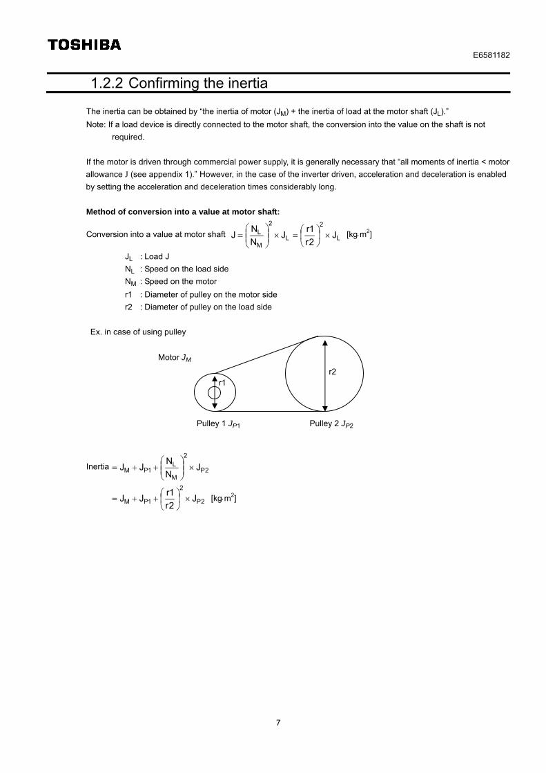
1.2.2 Confirming the inertia
The inertia can be obtained by “the inertia of motor (JM) + the inertia of load at the motor shaft (JL).”
Note: If a load device is directly connected to the motor shaft, the conversion into the value on the shaft is not
required.
If the motor is driven through commercial power supply, it is generally necessary that “all moments of inertia < motor
allowance J (see appendix 1).” However, in the case of the inverter driven, acceleration and deceleration is enabled
by setting the acceleration and deceleration times considerably long.
Method of conversion into a value at motor shaft:
Conversion into a value at motor shaft L
2
L
2
M
L J2r
1rJ
N
NJ
[kgm2]
JL : Load J
NL : Speed on the load side
NM : Speed on the motor
r1 : Diameter of pulley on the motor side
r2 : Diameter of pulley on the load side
Ex. in case of using pulley
Inertia 2P
2
M
L1PM J
N
NJJ
2P
2
1PM J2r
1rJJ
[kgm2]
Motor JM
Pulley 1 JP1 Pulley 2 JP2
r2 r1
E6581182
8
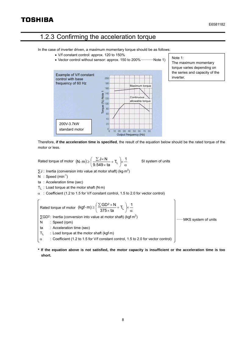
1.2.3 Confirming the acceleration torque
In the case of inverter driven, a maximum momentary torque should be as follows:
V/f constant control: approx. 120 to 150% Vector control without sensor: approx. 150 to 200%············Note 1)
Therefore, if the acceleration time is specified, the result of the equation below should be the rated torque of the
motor or less.
Rated torque of motor
1
Tta549.9
NJmN L・ SI system of units
∑J : Inertia (conversion into value at motor shaft) (kgm2)
N : Speed (min-1)
ta : Acceleration time (sec)
TL : Load torque at the motor shaft (Nm)
: Coefficient (1.2 to 1.5 for V/f constant control, 1.5 to 2.0 for vector control)
Rated torque of motor
1
Tta375
NGD)mkgf( L
2・
∑GD2 : Inertia (conversion into value at motor shaft) (kgfm2)
N : Speed (rpm)
ta : Acceleration time (sec)
TL : Load torque at the motor shaft (kgfm)
: Coefficient (1.2 to 1.5 for V/f constant control, 1.5 to 2.0 for vector control)
* If the equation above is not satisfied, the motor capacity is insufficient or the acceleration time is too
short.
200V-3.7kW
standard motor
Note 1: The maximum momentary torque varies depending on the series and capacity of the inverter.
Example of V/f constant control with base frequency of 60 Hz
Torq
ue (
%)
Not
e 1
Output frequency (Hz)
Maximum torque
Continuous
······ MKS system of units
allowable torque
E6581182
9
1.2.4 Confirming the deceleration torque
The deceleration (braking) torque driven by the inverter is as follows:
In case of only inverter used······· inverter capacity braking torque
0.13.7kW 30%20%
5.555kW 15%10%
75kW 10%
In case of using a standard optional braking resistor: 80% of torque
In case of using a resistor with a minimum allowable resistance: 80 to 150% of torque (For the
information on the maximum deceleration torque ( coefficient), see appendix 4.)
Therefore, if the deceleration time is specified, the result of the equation below should be the rated torque of the
motor or less.
Rated torque of motor
1
Ttb549.9
NJN L・m SI system of units
∑J : Inertia (conversion into value at motor shaft) (kgm2)
N : Speed (min-1)
tb : Acceleration time (sec)
TL : Load torque at the motor shaft (Nm)
: coefficient
Only inverter: 0.1 to 0.3
Standard optional braking resistor: 0.8
Resistor with minimum allowable resistance: 0.8 to 1.5
Rated torque of motor
1
Ttb375
NGD)mkgf( L
2・
∑J : Inertia (conversion into value at motor shaft) (kgfm2)
N : Speed (rpm)
tb : Acceleration time (sec)
TL : Load torque at the motor shaft (kgfm)
Only inverter: 0.1 to 0.3
Standard optional braking resistor: 0.8
Resistor with minimum allowable resistance: 0.8 to 1.5
* If the braking resistor is used, follow paragraph 1.1.2 to calculate the capacity of the braking resistor.
* If the equation above is not satisfied, the motor capacity is insufficient or the deceleration time is too
short.
······MKS system of units
E6581182
10
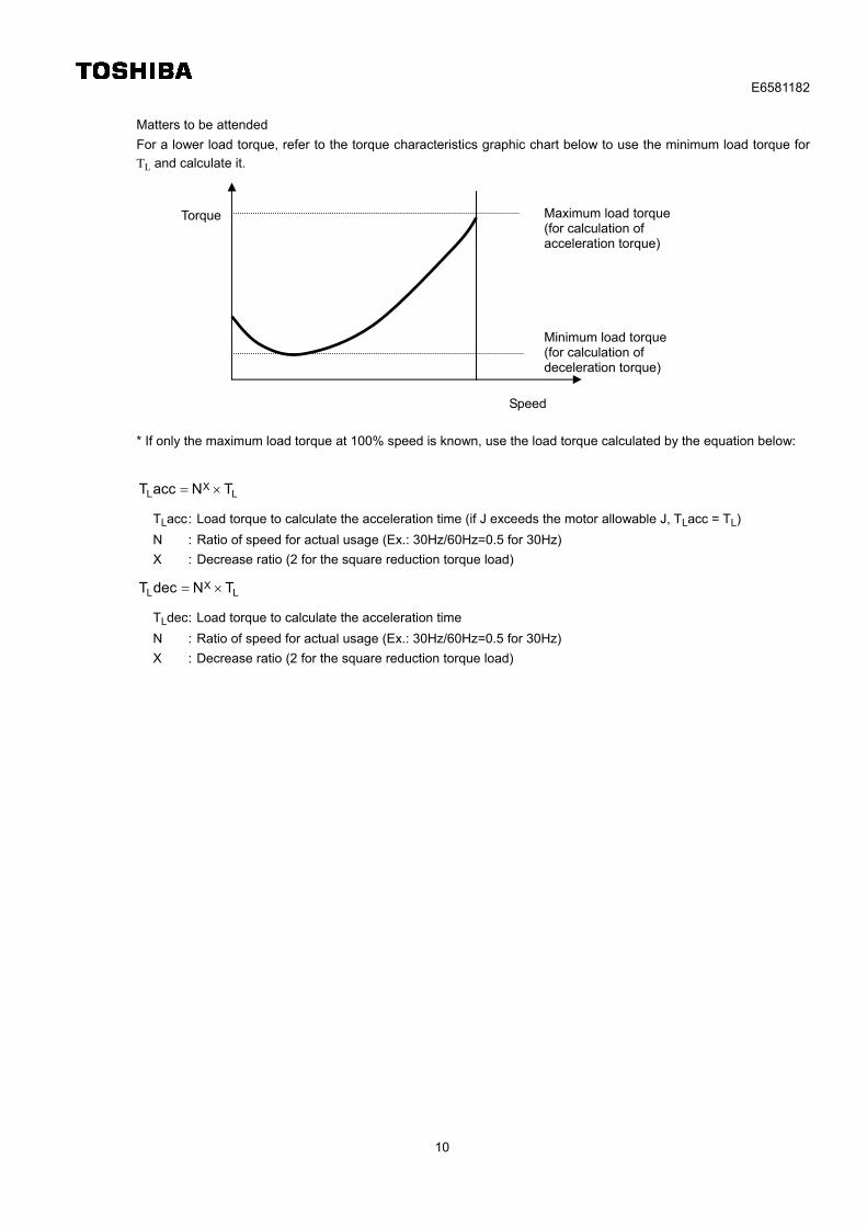
Matters to be attended
For a lower load torque, refer to the torque characteristics graphic chart below to use the minimum load torque for
TL and calculate it.
* If only the maximum load torque at 100% speed is known, use the load torque calculated by the equation below:
LX
L TNaccT
TLacc : Load torque to calculate the acceleration time (if J exceeds the motor allowable J, TLacc = TL)
N : Ratio of speed for actual usage (Ex.: 30Hz/60Hz=0.5 for 30Hz)
X : Decrease ratio (2 for the square reduction torque load)
LX
L TNdecT
TLdec : Load torque to calculate the acceleration time
N : Ratio of speed for actual usage (Ex.: 30Hz/60Hz=0.5 for 30Hz)
X : Decrease ratio (2 for the square reduction torque load)
Speed
Torque
Minimum load torque (for calculation of deceleration torque)
Maximum load torque (for calculation of acceleration torque)
E6581182
11
1.2.5 In case of the short-time acceleration/deceleration or starting torque of 150 % or more
If the short-time acceleration torque or starting torque of 150% or more is required, there is a case where only the
capacity of the inverter is increased to meet the requirement.
In paragraph 1.2.3 or 1.2.4, increase only the rated torque of motor by one frame (in the inverter capacity group,
large capacity by one) and confirm each item.
Ex.:
In case of that the motor decided in paragraph 1.2.1 and 1.2.2 is 2.2 kW
Use the rated torque of the 3.7 kW motor for the left side (motor rated torque) of paragraph 1.2.3 and 1.2.4.
R
RMM P
upPTupT (Nm)
TM up : Motor rated torque upper by one frame
PR up : Motor capacity upper by one frame
However, the load torque in a regular operation should be within the rated torques of the motor actually used.
E6581182
12
1.2.6 Calculation of the minimum acceleration/deceleration times
The minimum acceleration/deceleration times will be obtained with the below used in the previous paragraph:
Motor J (JM, GD2M)
Load J at the motor shaft (JL, GD2L)
Motor rated torque (TM)
Difference between revolutions (N)
Load torque at the motor shaft (TL)
(Use the value or more calculated by the equation below for the setting of acceleration/deceleration times of the
inverter.)
Setting of acceleration time:
If a smaller value than the calculated minimum acceleration time is set, an over-current protection or
over-current stall prevention may operate.
Setting of deceleration time:
If a smaller value than the calculated minimum deceleration time is set, an over-voltage protection or
over-voltage stall protection may operate.
Minimum acceleration time
LM
LMa TTa549.9
NJJt
SI system of units
a : Coefficient
V/f constant control: 1.2 to 1.5
Vector control: 1.5 to 2.0
Minimum acceleration time
LM
L2M2
TTa375
NGDGDta
··· MKS system of units
Minimum deceleration time
LM
LMa TTb549.9
NJJt
SI system of units
b : Coefficient
Only inverter: 0.1 to 0.3
Standard optional braking resistor: 0.8
Resistor with minimum allowable resistance: 0.8 to 1.5
Minimum deceleration time
LM
L2M2
TTb375
NGDGDta
··· MKS system of units
* If only the capacity of the inverter is increased by one frame, use the rated torque of the motor increased by one
frame for TM.
E6581182
13
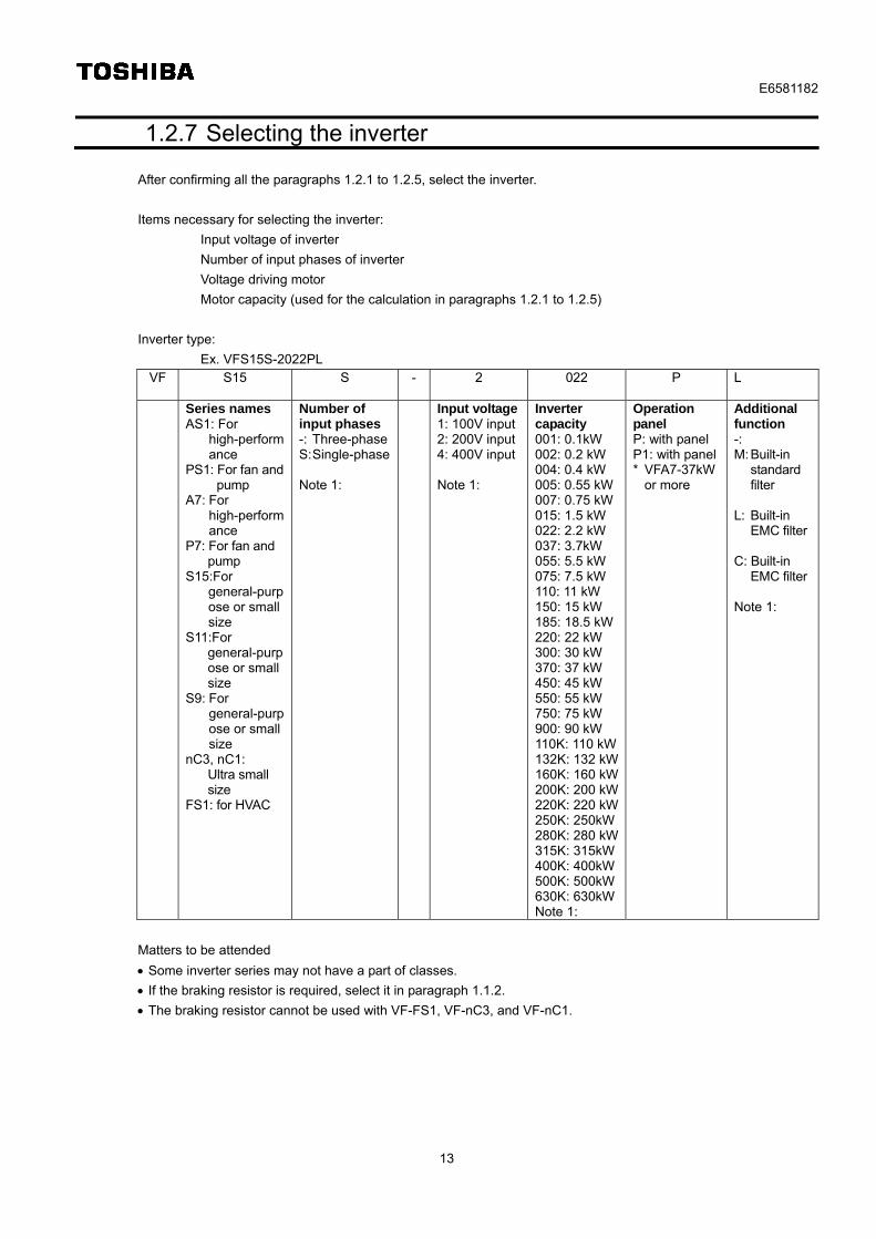
1.2.7 Selecting the inverter
After confirming all the paragraphs 1.2.1 to 1.2.5, select the inverter.
Items necessary for selecting the inverter:
Input voltage of inverter
Number of input phases of inverter
Voltage driving motor
Motor capacity (used for the calculation in paragraphs 1.2.1 to 1.2.5)
Inverter type:
Ex. VFS15S-2022PL VF S15 S - 2 022 P
L
Series names AS1: For
high-performance
PS1: For fan and pump
A7: For high-performance
P7: For fan and pump
S15:For general-purpose or small size
S11:For general-purpose or small size
S9: For general-purpose or small size
nC3, nC1: Ultra small size
FS1: for HVAC
Number of input phases -: Three-phaseS: Single-phase Note 1:
Input voltage1: 100V input2: 200V input4: 400V input Note 1:
Inverter capacity 001: 0.1kW 002: 0.2 kW 004: 0.4 kW 005: 0.55 kW007: 0.75 kW015: 1.5 kW 022: 2.2 kW 037: 3.7kW 055: 5.5 kW 075: 7.5 kW 110: 11 kW 150: 15 kW 185: 18.5 kW220: 22 kW 300: 30 kW 370: 37 kW 450: 45 kW 550: 55 kW 750: 75 kW 900: 90 kW 110K: 110 kW132K: 132 kW160K: 160 kW200K: 200 kW220K: 220 kW250K: 250kW280K: 280 kW315K: 315kW400K: 400kW500K: 500kW630K: 630kWNote 1:
Operation panel P: with panel P1: with panel * VFA7-37kW
or more
Additional function -: M: Built-in
standard filter
L: Built-in
EMC filter C: Built-in
EMC filter Note 1:
Matters to be attended
Some inverter series may not have a part of classes.
If the braking resistor is required, select it in paragraph 1.1.2.
The braking resistor cannot be used with VF-FS1, VF-nC3, and VF-nC1.
E6581182
14
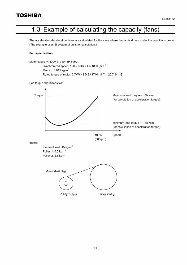
1.3 Example of calculating the capacity (fans)
The acceleration/deceleration times are calculated for the case where the fan is driven under the conditions below.
(The example uses SI system of units for calculation.)
Fan specification:
Motor capacity: 400V-3, 7kW-4P-60Hz
Synchronized speed: 120 60Hz 4 = 1800 [min-1]
Motor J: 0.015 kgm2
Rated torque of motor: 3.7kW 9549 / 1710 min-1 = 20.7 [N・m]
Fan torque characteristics:
Inertia:
Inertia of load: 15 kgm2
Pulley 1: 0.5 kgm2
Pulley 2: 2.5 kgm2
Motor shaft (JM)
Pulley 1 (JP1) Pulley 2 (JP2)
Speed
Torque
100%
(600rpm)
Minimum load torque ······ 15 Nm
(for calculation of deceleration torque)
Maximum load torque ····· 60 Nm
(for calculation of acceleration torque)
E6581182
15
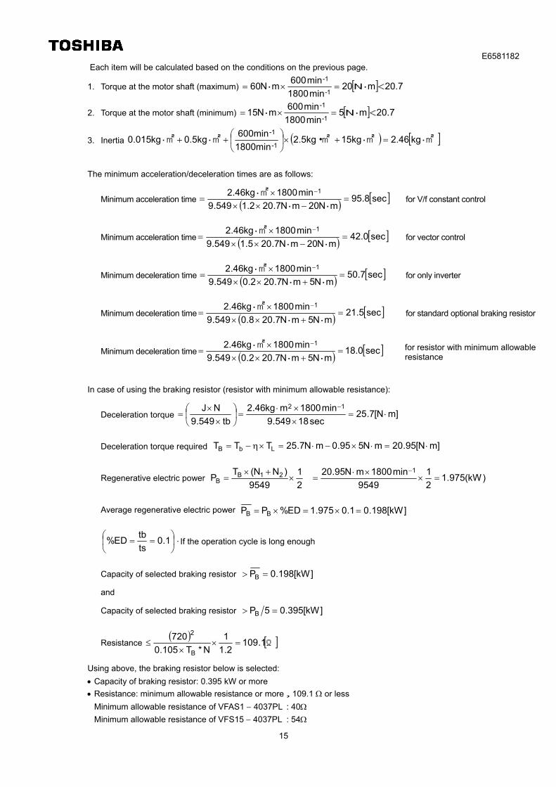
Each item will be calculated based on the conditions on the previous page.
1. Torque at the motor shaft (maximum) 20.7m20min1800
min600mN60
1-
-1<N・・
2. Torque at the motor shaft (minimum) 20.7m5min1800
min600mN15
1-
-1<N・・
3. Inertia ・kg2.46・15kg・2.5kg1800min
600min0.5kgkg015.0
1-
-1
・・
The minimum acceleration/deceleration times are as follows:
Minimum acceleration time sec95.8mN20mN7.202.1549.9
min1800kg46.2 1
・・
・ for V/f constant control
Minimum acceleration time sec42.0mN20mN7.205.1549.9
min1800kg46.2 1
・・
・ for vector control
Minimum deceleration time sec50.7mN5mN7.202.0549.9
min1800kg46.2 1
・・
・ for only inverter
Minimum deceleration time sec21.5mN5mN7.208.0549.9
min1800kg46.2 1
・・
・ for standard optional braking resistor
Minimum deceleration time sec18.0mN5mN7.202.0549.9
min1800kg46.2 1
・・
・
In case of using the braking resistor (resistor with minimum allowable resistance):
Deceleration torque ]mN[7.25sec18549.9
min1800mkg46.2
tb549.9
NJ 12
Deceleration torque required ]mN[95.20mN595.0mN7.25TTT LbB
Regenerative electric power )kW(975.12
1
9549
min1800mN95.20
2
1
9549
)NN(TP
121B
B
Average regenerative electric power ]kW[198.01.0975.1ED%PP BB
1.0ts
tbED% · If the operation cycle is long enough
Capacity of selected braking resistor ]kW[198.0PB
and
Capacity of selected braking resistor ]kW[395.05PB
Resistance Ω1.109
2.1
1
N*T105.0
720
B
2
Using above, the braking resistor below is selected:
Capacity of braking resistor: 0.395 kW or more
Resistance: minimum allowable resistance or more,109.1 or less
Minimum allowable resistance of VFAS1 4037PL : 40
Minimum allowable resistance of VFS15 4037PL : 54
for resistor with minimum allowable resistance
E6581182
16
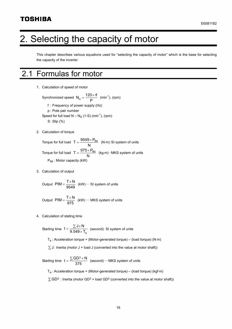
2. Selecting the capacity of motor
This chapter describes various equations used for “selecting the capacity of motor” which is the base for selecting
the capacity of the inverter.
2.1 Formulas for motor
1. Calculation of speed of motor
Synchronized speed P
120N
fs
(min-1), (rpm)
f : Frequency of power supply (Hz)
p : Pole pair number
Speed for full load N NS (1-S) (min-1), (rpm)
S : Slip (%)
2. Calculation of torque
Torque for full load N
P9549T IM (Nm)·SI system of units
Torque for full load N
P975T IM (kgm) ··MKS system of units
PIM : Motor capacity (kW)
3. Calculation of output
Output 9549
NTPIM
(kW)···· SI system of units
Output 975
NTPIM
(kW) ···· MKS system of units
4. Calculation of stating time
Starting time aT549.9
NJt
(second) ·SI system of units
Ta : Acceleration torque = (Motor-generated torque) – (load torque) (Nm)
J : Inertia (motor J + load J (converted into the value at motor shaft))
Starting time 375
NGDt
2 (second) ····MKS system of units
Ta : Acceleration torque = (Motor-generated torque) – (load torque) (kgfm)
2GD : Inertia (motor GD2 + load GD2 (converted into the value at motor shaft))
E6581182
17
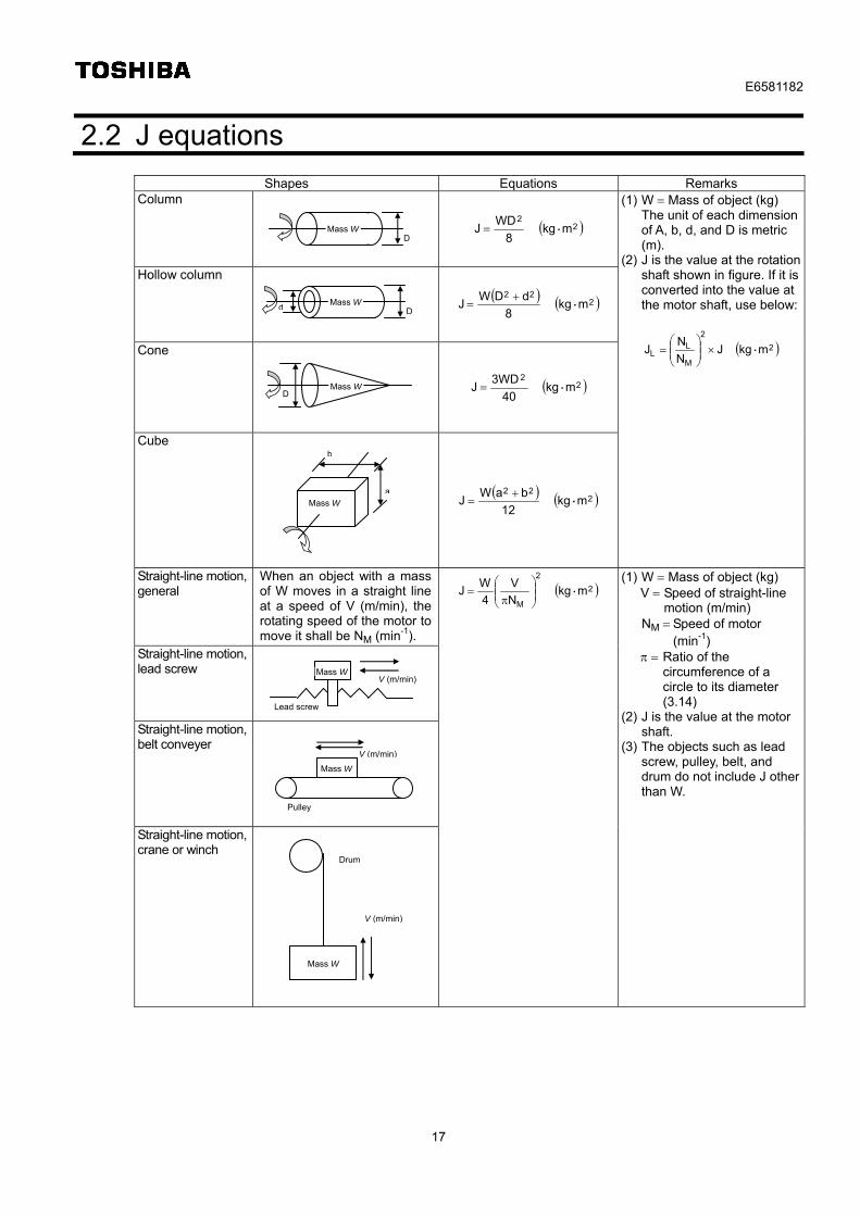
2.2 J equations
Shapes Equations Remarks Column
22
mkg8
WDJ ・
Hollow column
222
mkg8
dDW J ・
Cone
22
mkg40
3WDJ ・
Cube
222
mkg12
baWJ ・
(1) W Mass of object (kg) The unit of each dimension
of A, b, d, and D is metric (m).
(2) J is the value at the rotation shaft shown in figure. If it is converted into the value at the motor shaft, use below:
2
2
M
LL mkgJ
N
NJ ・
Straight-line motion, general
When an object with a mass of W moves in a straight line at a speed of V (m/min), the rotating speed of the motor to move it shall be NM (min-1).
Straight-line motion, lead screw
Straight-line motion, belt conveyer
Straight-line motion, crane or winch
2
2
M
mkg N
V
4
WJ ・
(1) W Mass of object (kg) V Speed of straight-line
motion (m/min) NM Speed of motor
(min-1) Ratio of the
circumference of a circle to its diameter (3.14)
(2) J is the value at the motor shaft.
(3) The objects such as lead screw, pulley, belt, and drum do not include J other than W.
Mass WD
Mass Wd D
Mass WD
Mass W a
b
Mass W
Lead screw
V (m/min)
Pulley
Mass W
V (m/min)
Mass W
V (m/min)
Drum
E6581182
18
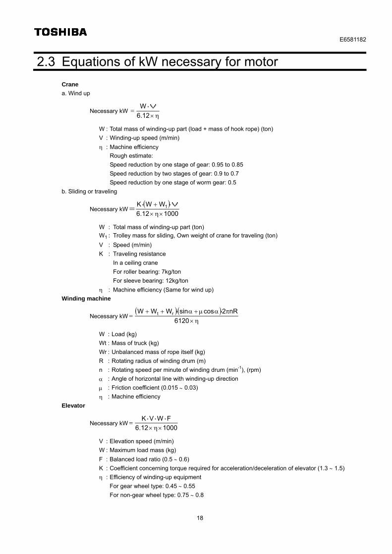
2.3 Equations of kW necessary for motor
Crane
a. Wind up
Necessary kW
6.12
W・V
W : Total mass of winding-up part (load + mass of hook rope) (ton)
V : Winding-up speed (m/min)
: Machine efficiency
Rough estimate:
Speed reduction by one stage of gear: 0.95 to 0.85
Speed reduction by two stages of gear: 0.9 to 0.7
Speed reduction by one stage of worm gear: 0.5
b. Sliding or traveling
Necessary kW
10006.12
WWK 1
・V・
=
W : Total mass of winding-up part (ton)
W1 : Trolley mass for sliding, Own weight of crane for traveling (ton)
V : Speed (m/min)
K : Traveling resistance
In a ceiling crane
For roller bearing: 7kg/ton
For sleeve bearing: 12kg/ton
: Machine efficiency (Same for wind up)
Winding machine
Necessary kW
6120
nR2cossinWWW rt ・・
W : Load (kg)
Wt : Mass of truck (kg)
Wr : Unbalanced mass of rope itself (kg)
R : Rotating radius of winding drum (m)
n : Rotating speed per minute of winding drum (min-1), (rpm)
: Angle of horizontal line with winding-up direction
: Friction coefficient (0.015 0.03)
: Machine efficiency
Elevator
Necessary kW100012.6
FWVK
・・・
V : Elevation speed (m/min)
W : Maximum load mass (kg)
F : Balanced load ratio (0.5 0.6)
K : Coefficient concerning torque required for acceleration/deceleration of elevator (1.3 1.5)
: Efficiency of winding-up equipment
For gear wheel type: 0.45 0.55
For non-gear wheel type: 0.75 0.8
E6581182
19
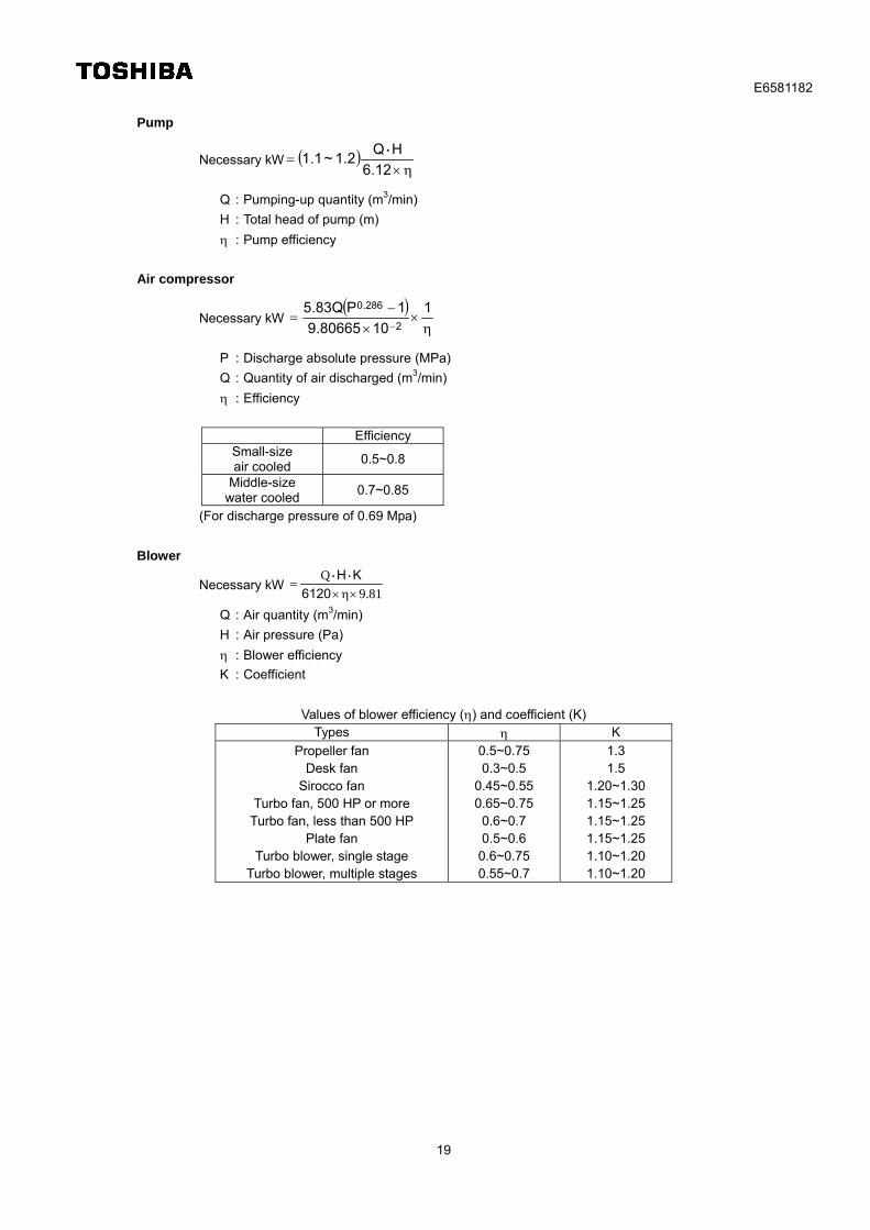
Pump
Necessary kW
12.6
HQ1.2~1.1
・
Q : Pumping-up quantity (m3/min)
H : Total head of pump (m)
: Pump efficiency
Air compressor
Necessary kW
1
1080665.9
1PQ83.52
286.0
P : Discharge absolute pressure (MPa)
Q : Quantity of air discharged (m3/min)
: Efficiency
Efficiency
Small-size air cooled
0.5~0.8
Middle-size water cooled
0.7~0.85
(For discharge pressure of 0.69 Mpa)
Blower
Necessary kW 81.9
Q
6120
KH・・
Q : Air quantity (m3/min)
H : Air pressure (Pa)
: Blower efficiency
K : Coefficient
Values of blower efficiency () and coefficient (K) Types K
Propeller fan Desk fan
Sirocco fan Turbo fan, 500 HP or more
Turbo fan, less than 500 HP Plate fan
Turbo blower, single stage Turbo blower, multiple stages
0.5~0.75 0.3~0.5
0.45~0.55 0.65~0.75
0.6~0.7 0.5~0.6
0.6~0.75 0.55~0.7
1.3 1.5
1.20~1.30 1.15~1.25 1.15~1.25 1.15~1.25 1.10~1.20 1.10~1.20
E6581182
20
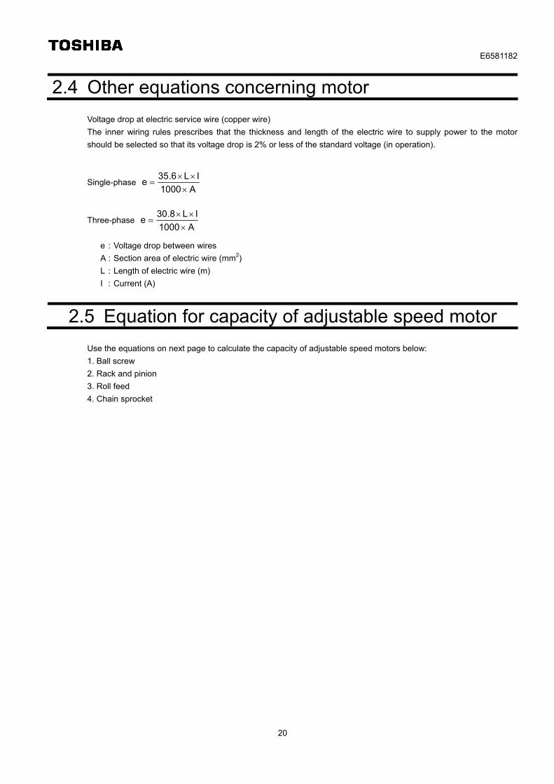
2.4 Other equations concerning motor
Voltage drop at electric service wire (copper wire)
The inner wiring rules prescribes that the thickness and length of the electric wire to supply power to the motor
should be selected so that its voltage drop is 2% or less of the standard voltage (in operation).
Single-phase A1000
IL6.35e
Three-phase A1000
IL8.30e
e : Voltage drop between wires
A : Section area of electric wire (mm2)
L : Length of electric wire (m)
I : Current (A)
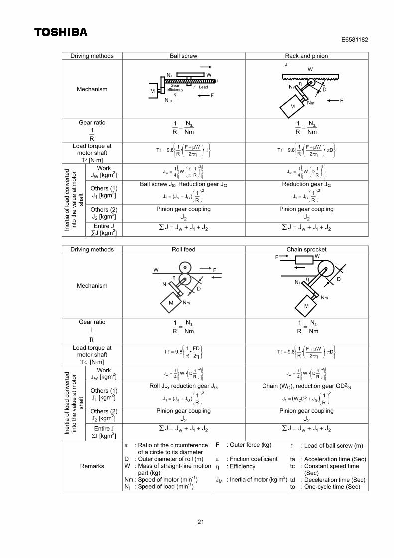
2.5 Equation for capacity of adjustable speed motor
Use the equations on next page to calculate the capacity of adjustable speed motors below:
1. Ball screw
2. Rack and pinion
3. Roll feed
4. Chain sprocket
E6581182
21
Driving methods Ball screw Rack and pinion
Mechanism
Gear ratio
R
1 Nm
N
R
1 1 Nm
N
R
1 1
Load torque at motor shaft
Tℓ [Nm]
・・2
WF
R
19.8T
D2
WF
R
19.8T ・・
Work JW [kgm2]
2
w R
1W
4
1J ・・
2
w R
1DW
4
1J ・
Others (1)J1 [kgm2]
Ball screw JS, Reduction gear JG 2
GS1 R
1)J(JJ
Reduction gear JG 2
G1 R
1JJ
Others (2)J2 [kgm2]
Pinion gear coupling J2
Pinion gear coupling J2
Iner
tia o
f loa
d co
nver
ted
into
the
valu
e at
mot
or
shaf
t
Entire J ∑J [kgm2]
21w JJJJ 21w JJJJ
Driving methods Roll feed Chain sprocket
Mechanism
Gear ratio
R
1 Nm
N
R
1 1 Nm
N
R
1 1
Load torque at motor shaft
Tℓ [Nm]
2
FD
R
19.8T ・
D2
WF
R
19.8T ・・
Work JW [kgm2]
2
w R
1DW
4
1J ・
2
w R
1DW
4
1J ・
Others (1)J1 [kgm2]
Roll JR, reduction gear JG 2
GR1 R
1)J(JJ
Chain (WC), reduction gear GD2G
2
G2
C1 R
1JDWJ
Others (2)J2 [kgm2]
Pinion gear coupling J2
Pinion gear coupling J2
Iner
tia o
f loa
d co
nver
ted
into
the
valu
e at
mot
or
shaf
t
Entire J J [kgm2]
21w JJJJ 21w JJJJ
Remarks
: Ratio of the circumference of a circle to its diameter
D : Outer diameter of roll (m) W : Mass of straight-line motion
part (kg) Nm : Speed of motor (min-1) Nl : Speed of load (min-1)
F : Outer force (kg)
: Friction coefficient : Efficiency JM : Inertia of motor (kgm2)
: Lead of ball screw (m) ta : Acceleration time (Sec)tc : Constant speed time
(Sec) td : Deceleration time (Sec)to : One-cycle time (Sec)
Gear efficiency
M
F
μWN1
Nm
Lead
W
FNm
N1 η
μ
M
D
M
F
D
Nm
N1
ηW
η
F
N1
Nm
W
M
D
E6581182
22
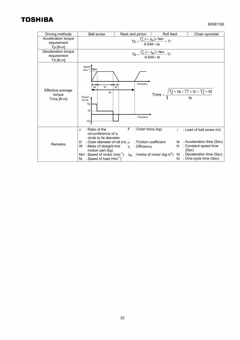
Driving methods Ball screw Rack and pinion Roll feed Chain sprocket
Acceleration torque requirement
Tp [Nm]
T
ta9.549
NmJJTp M
Deceleration torque requirement
Td [Nm]
T-
tb9.549
NmJJTp M
Effective average torque
Trms [Nm]
to
tdTtcTtaTTrms
2d
22p
Remarks
: Ratio of the circumference of a circle to its diameter
D : Outer diameter of roll (m)W : Mass of straight-line
motion part (kg) Nm : Speed of motor (min-1)Nl : Speed of load (min-1)
F : Outer force (kg)
: Friction coefficient : Efficiency JM : Inertia of motor (kgm2)
: Lead of ball screw (m)
ta : Acceleration time (Sec)tc : Constant speed time
(Sec) td : Deceleration time (Sec)to : One-cycle time (Sec)
-Td
Tℓ
tdtc
Speed (min-1) Nm
ta Time(sec)
Torque (N・m)
Time(sec)
to
Tp
E6581182
23
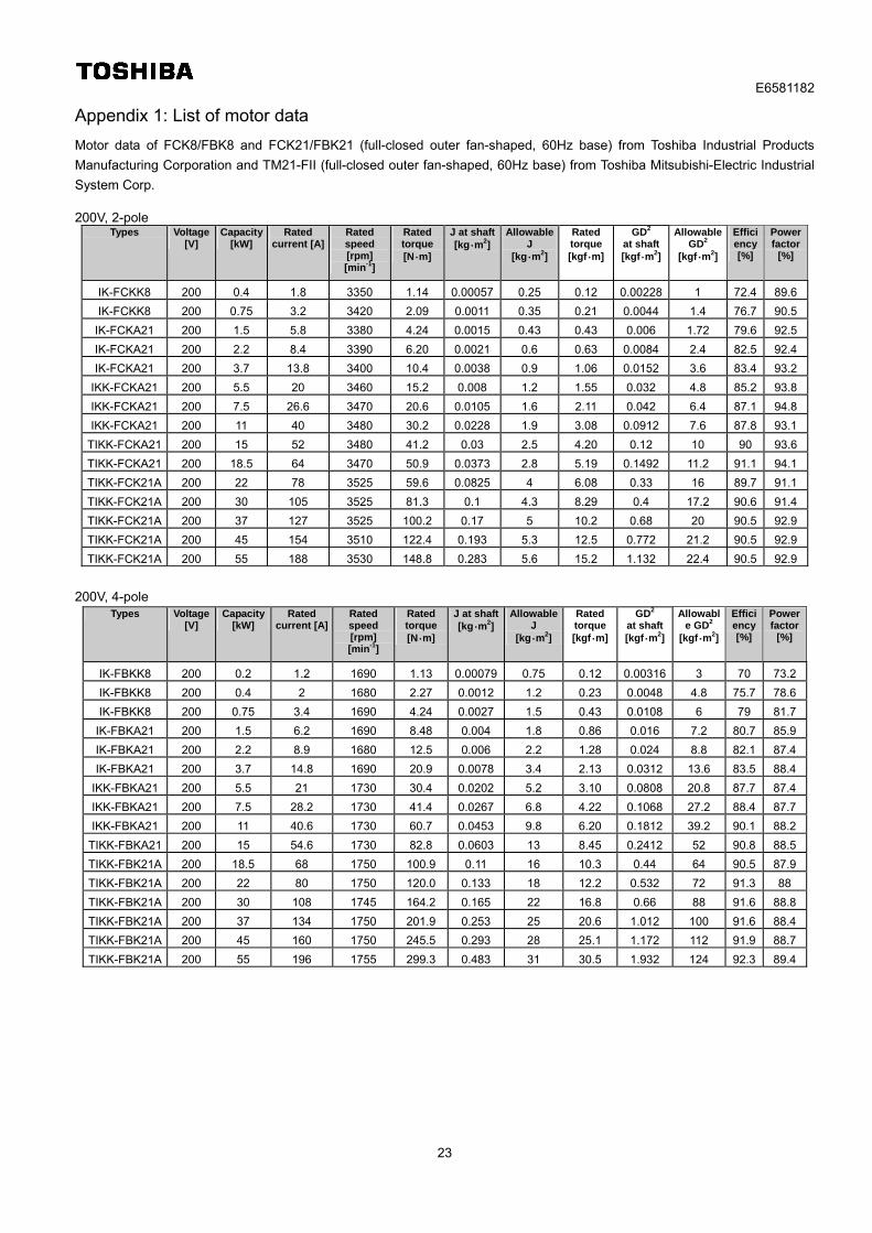
Appendix 1: List of motor data
Motor data of FCK8/FBK8 and FCK21/FBK21 (full-closed outer fan-shaped, 60Hz base) from Toshiba Industrial Products
Manufacturing Corporation and TM21-FII (full-closed outer fan-shaped, 60Hz base) from Toshiba Mitsubishi-Electric Industrial
System Corp. 200V, 2-pole
Types Voltage [V]
Capacity [kW]
Rated current [A]
Rated speed [rpm] [min-1]
Rated torque[N・m]
J at shaft[kg・m2]
Allowable J
[kg・m2]
Rated torque[kgf・m]
GD2 at shaft
[kgf・m2]
Allowable GD2
[kgf・m2]
Efficiency [%]
Power factor
[%]
IK-FCKK8 200 0.4 1.8 3350 1.14 0.00057 0.25 0.12 0.00228 1 72.4 89.6
IK-FCKK8 200 0.75 3.2 3420 2.09 0.0011 0.35 0.21 0.0044 1.4 76.7 90.5
IK-FCKA21 200 1.5 5.8 3380 4.24 0.0015 0.43 0.43 0.006 1.72 79.6 92.5
IK-FCKA21 200 2.2 8.4 3390 6.20 0.0021 0.6 0.63 0.0084 2.4 82.5 92.4
IK-FCKA21 200 3.7 13.8 3400 10.4 0.0038 0.9 1.06 0.0152 3.6 83.4 93.2
IKK-FCKA21 200 5.5 20 3460 15.2 0.008 1.2 1.55 0.032 4.8 85.2 93.8
IKK-FCKA21 200 7.5 26.6 3470 20.6 0.0105 1.6 2.11 0.042 6.4 87.1 94.8
IKK-FCKA21 200 11 40 3480 30.2 0.0228 1.9 3.08 0.0912 7.6 87.8 93.1
TIKK-FCKA21 200 15 52 3480 41.2 0.03 2.5 4.20 0.12 10 90 93.6
TIKK-FCKA21 200 18.5 64 3470 50.9 0.0373 2.8 5.19 0.1492 11.2 91.1 94.1
TIKK-FCK21A 200 22 78 3525 59.6 0.0825 4 6.08 0.33 16 89.7 91.1
TIKK-FCK21A 200 30 105 3525 81.3 0.1 4.3 8.29 0.4 17.2 90.6 91.4
TIKK-FCK21A 200 37 127 3525 100.2 0.17 5 10.2 0.68 20 90.5 92.9
TIKK-FCK21A 200 45 154 3510 122.4 0.193 5.3 12.5 0.772 21.2 90.5 92.9
TIKK-FCK21A 200 55 188 3530 148.8 0.283 5.6 15.2 1.132 22.4 90.5 92.9
200V, 4-pole Types Voltage
[V] Capacity
[kW] Rated
current [A] Rated speed [rpm] [min-1]
Rated torque[N・m]
J at shaft[kg・m2]
Allowable J
[kg・m2]
Rated torque[kgf・m]
GD2 at shaft
[kgf・m2]
Allowable GD2
[kgf・m2]
Efficiency [%]
Power factor
[%]
IK-FBKK8 200 0.2 1.2 1690 1.13 0.00079 0.75 0.12 0.00316 3 70 73.2
IK-FBKK8 200 0.4 2 1680 2.27 0.0012 1.2 0.23 0.0048 4.8 75.7 78.6
IK-FBKK8 200 0.75 3.4 1690 4.24 0.0027 1.5 0.43 0.0108 6 79 81.7
IK-FBKA21 200 1.5 6.2 1690 8.48 0.004 1.8 0.86 0.016 7.2 80.7 85.9
IK-FBKA21 200 2.2 8.9 1680 12.5 0.006 2.2 1.28 0.024 8.8 82.1 87.4
IK-FBKA21 200 3.7 14.8 1690 20.9 0.0078 3.4 2.13 0.0312 13.6 83.5 88.4
IKK-FBKA21 200 5.5 21 1730 30.4 0.0202 5.2 3.10 0.0808 20.8 87.7 87.4
IKK-FBKA21 200 7.5 28.2 1730 41.4 0.0267 6.8 4.22 0.1068 27.2 88.4 87.7
IKK-FBKA21 200 11 40.6 1730 60.7 0.0453 9.8 6.20 0.1812 39.2 90.1 88.2
TIKK-FBKA21 200 15 54.6 1730 82.8 0.0603 13 8.45 0.2412 52 90.8 88.5
TIKK-FBK21A 200 18.5 68 1750 100.9 0.11 16 10.3 0.44 64 90.5 87.9
TIKK-FBK21A 200 22 80 1750 120.0 0.133 18 12.2 0.532 72 91.3 88
TIKK-FBK21A 200 30 108 1745 164.2 0.165 22 16.8 0.66 88 91.6 88.8
TIKK-FBK21A 200 37 134 1750 201.9 0.253 25 20.6 1.012 100 91.6 88.4
TIKK-FBK21A 200 45 160 1750 245.5 0.293 28 25.1 1.172 112 91.9 88.7
TIKK-FBK21A 200 55 196 1755 299.3 0.483 31 30.5 1.932 124 92.3 89.4
E6581182
24
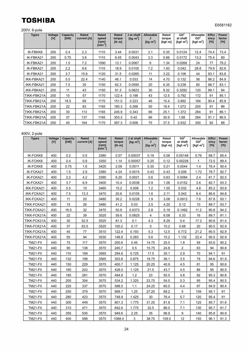
200V, 6-pole Types Voltage
[V] Capacity
[kW] Rated
current [A] Rated speed [rpm] [min-1]
Rated torque[N・m]
J at shaft[kg・m2]
Allowable J
[kg・m2]
Rated torque[kgf・m]
GD2 at shaft
[kgf・m2]
Allowable GD2
[kgf・m2]
Efficiency [%]
Power factor
[%]
IK-FBKK8 200 0.4 2.3 1110 3.44 0.0031 3.1 0.35 0.0124 12.4 74.4 73.4
IK-FBKA21 200 0.75 3.6 1110 6.45 0.0043 3.3 0.66 0.0172 13.2 75.4 80
IK-FBKA21 200 1.5 7.2 1090 13.1 0.0067 6 1.34 0.0268 24 77 79.2
IK-FBKA21 200 2.2 9.6 1110 18.9 0.0105 7.2 1.93 0.042 28.8 79.9 82.6
IK-FBKA21 200 3.7 15.6 1120 31.5 0.0265 11 3.22 0.106 44 83.1 83.8
IKK-FBKA21 200 5.5 22.4 1140 46.1 0.033 14 4.70 0.132 56 86.2 84.9
IKK-FBKA21 200 7.5 30 1150 62.3 0.0595 20 6.35 0.238 80 88.7 83.1
IKK-FBKA21 200 11 43 1150 91.3 0.0823 30 9.32 0.3292 120 89.1 84
TIKK-FBK21A 200 15 57 1170 122.4 0.198 43 12.5 0.792 172 91 85.1
TIKK-FBK21A 200 18.5 69 1170 151.0 0.223 46 15.4 0.892 184 90.4 85.8
TIKK-FBK21A 200 22 83 1165 180.3 0.268 50 18.4 1.072 200 91 86
TIKK-FBK21A 200 30 113 1165 245.9 0.343 66 25.1 1.372 264 91 86.1
TIKK-FBK21A 200 37 137 1165 303.3 0.42 66 30.9 1.68 264 91.1 86.5
TIKK-FBK21A 200 45 164 1170 367.3 0.658 75 37.5 2.632 300 92 88
400V, 2-pole Types Voltage
[V] Capacity
[kW] Rated
current [A] Rated speed [rpm] [min-1]
Rated torque[N・m]
J at shaft[kg・m2]
Allowable J
[kg・m2]
Rated torque[kgf・m]
GD2 at shaft
[kgf・m2]
Allowable GD2
[kgf・m2]
Efficiency [%]
Power factor
[%]
IK-FCKK8 400 0.2 0.5 3380 0.57 0.00037 0.19 0.06 0.00148 0.76 68.7 85.4
IK-FCKK8 400 0.4 0.9 3350 1.14 0.00057 0.25 0.12 0.00228 1 72.5 89.4
IK-FCKK8 400 0.75 1.6 3420 2.09 0.0011 0.35 0.21 0.0044 1.4 76.4 90.4
IK-FCKA21 400 1.5 2.9 3380 4.24 0.0015 0.43 0.43 0.006 1.72 78.7 92.7
IK-FCKA21 400 2.2 4.2 3390 6.20 0.0021 0.6 0.63 0.0084 2.4 81.7 92.5
IK-FCKA21 400 3.7 6.9 3400 10.4 0.0038 0.9 1.06 0.0152 3.6 82.7 93.3
IKK-FCKA21 400 5.5 10 3460 15.2 0.008 1.2 1.55 0.032 4.8 85.2 93.8
IKK-FCKA21 400 7.5 13.3 3470 20.6 0.0105 1.6 2.11 0.042 6.4 86.6 94.8
IKK-FCKA21 400 11 20 3480 30.2 0.0228 1.9 3.08 0.0912 7.6 87.8 93.1
TIKK-FCKA21 400 15 26 3480 41.2 0.03 2.5 4.20 0.12 10 89.7 93.7
TIKK-FCKA21 400 18.5 32 3470 50.9 0.0373 2.8 5.19 0.1492 11.2 90.8 94.2
TIKK-FCK21A 400 22 39 3525 59.6 0.0825 4 6.08 0.33 16 89.7 91.1
TIKK-FCK21A 400 30 52.5 3525 81.3 0.1 4.3 8.29 0.4 17.2 90.6 91.4
TIKK-FCK21A 400 37 63.5 3525 100.2 0.17 5 10.2 0.68 20 90.5 92.9
TIKK-FCK21A 400 45 77 3510 122.4 0.193 5.3 12.5 0.772 21.2 90.5 92.9
TIKK-FCK21A 400 55 94 3530 148.8 0.283 5.6 15.2 1.132 22.4 90.5 92.9
TM21-FII 440 75 117 3570 200.6 0.45 14.75 20.5 1.8 59 93.6 90.2
TM21-FII 440 90 138 3570 240.7 0.5 15.75 24.6 2 63 94 90.8
TM21-FII 440 110 169 3565 294.6 0.725 17.5 30.1 2.9 70 94.1 91
TM21-FII 440 132 199 3565 353.6 0.875 19.75 36.1 3.5 79 94.6 91.9
TM21-FII 440 150 229 3575 400.7 1.125 20.25 40.9 4.5 81 95 90.6
TM21-FII 440 160 243 3570 428.0 1.125 21.5 43.7 4.5 86 95 90.9
TM21-FII 440 185 281 3570 494.8 1.2 23 50.5 4.8 92 95.3 90.8
TM21-FII 440 200 304 3575 534.2 1.325 23.75 54.5 5.3 95 95.4 90.5
TM21-FII 440 220 337 3570 588.5 1.1 24.25 60.0 4.4 97 94.9 90.4
TM21-FII 440 250 379 3570 668.7 1.25 27.25 68.2 5 109 95.1 91
TM21-FII 440 280 423 3570 748.9 1.425 30 76.4 5.7 120 95.4 91
TM21-FII 440 300 449 3575 801.3 1.775 31.25 81.8 7.1 125 95.7 91.6
TM21-FII 440 315 471 3570 842.6 1.775 32.5 86.0 7.1 130 95.7 91.7
TM21-FII 440 355 535 3570 949.6 2.25 35 96.9 9 140 95.8 90.9
TM21-FII 440 400 598 3575 1068.4 3 38.75 109.0 12 155 96.1 91.3
E6581182
25
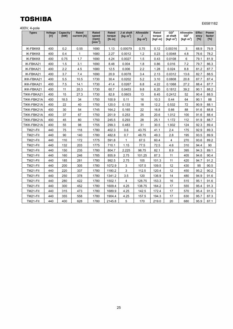
400V, 4-pole Types Voltage
[V] Capacity
[kW] Rated
current [A] Rated speed [rpm] [min-1]
Rated torque[N・m]
J at shaft[kg・m2]
Allowable J
[kg・m2]
Rated torque[kgf・m]
GD2 at shaft
[kgf・m2]
Allowable GD2
[kgf・m2]
Efficiency [%]
Power factor
[%]
IK-FBKK8 400 0.2 0.55 1690 1.13 0.00079 0.75 0.12 0.00316 3 68.9 79.9
IK-FBKK8 400 0.4 1 1680 2.27 0.0012 1.2 0.23 0.0048 4.8 76.6 78.2
IK-FBKK8 400 0.75 1.7 1690 4.24 0.0027 1.5 0.43 0.0108 6 79.1 81.9
IK-FBKA21 400 1.5 3.1 1690 8.48 0.004 1.8 0.86 0.016 7.2 79.7 86.3
IK-FBKA21 400 2.2 4.5 1680 12.5 0.006 2.2 1.28 0.024 8.8 81.2 87.7
IK-FBKA21 400 3.7 7.4 1690 20.9 0.0078 3.4 2.13 0.0312 13.6 82.7 88.5
IKK-FBKA21 400 5.5 10.5 1730 30.4 0.0202 5.2 3.10 0.0808 20.8 87.7 87.4
IKK-FBKA21 400 7.5 14.1 1730 41.4 0.0267 6.8 4.22 0.1068 27.2 88.4 87.7
IKK-FBKA21 400 11 20.3 1730 60.7 0.0453 9.8 6.20 0.1812 39.2 90.1 88.2
TIKK-FBKA21 400 15 27.3 1730 82.8 0.0603 13 8.45 0.2412 52 90.4 88.5
TIKK-FBK21A 400 18.5 34 1750 100.9 0.11 16 10.3 0.44 64 90.1 88
TIKK-FBK21A 400 22 40 1750 120.0 0.133 18 12.2 0.532 72 90.9 88.1
TIKK-FBK21A 400 30 54 1745 164.2 0.165 22 16.8 0.66 88 91.6 88.8
TIKK-FBK21A 400 37 67 1750 201.9 0.253 25 20.6 1.012 100 91.6 88.4
TIKK-FBK21A 400 45 80 1750 245.5 0.293 28 25.1 1.172 112 91.9 88.7
TIKK-FBK21A 400 55 98 1755 299.3 0.483 31 30.5 1.932 124 92.3 89.4
TM21-FII 440 75 118 1780 402.3 0.6 43.75 41.1 2.4 175 92.9 89.3
TM21-FII 440 90 140 1780 482.8 0.7 48.75 49.3 2.8 195 93.5 89.9
TM21-FII 440 110 172 1775 591.8 1 67.5 60.4 4 270 93.6 89.2
TM21-FII 440 132 203 1775 710.1 1.15 77.5 72.5 4.6 310 94.4 90
TM21-FII 440 150 235 1780 804.7 2.225 98.75 82.1 8.9 395 94.3 89.1
TM21-FII 440 160 246 1785 855.9 2.75 101.25 87.3 11 405 94.6 90.4
TM21-FII 440 185 281 1780 992.5 2.75 105 101.3 11 420 94.7 91.2
TM21-FII 440 200 305 1780 1072.9 3 107.5 109.5 12 430 95 90.5
TM21-FII 440 220 337 1780 1180.2 3 112.5 120.4 12 450 95.2 90.2
TM21-FII 440 250 378 1780 1341.2 3.5 120 136.9 14 480 94.9 91.6
TM21-FII 440 280 422 1780 1502.1 4 128.75 153.3 16 515 95.1 91.6
TM21-FII 440 300 452 1780 1609.4 4.25 138.75 164.2 17 555 95.4 91.3
TM21-FII 440 315 473 1780 1689.9 4.25 142.5 172.4 17 570 95.4 91.5
TM21-FII 440 355 558 1780 1904.4 4.25 157.5 194.3 17 630 95.7 87.3
TM21-FII 440 400 628 1780 2145.8 5 170 219.0 20 680 95.9 87.1
E6581182
26
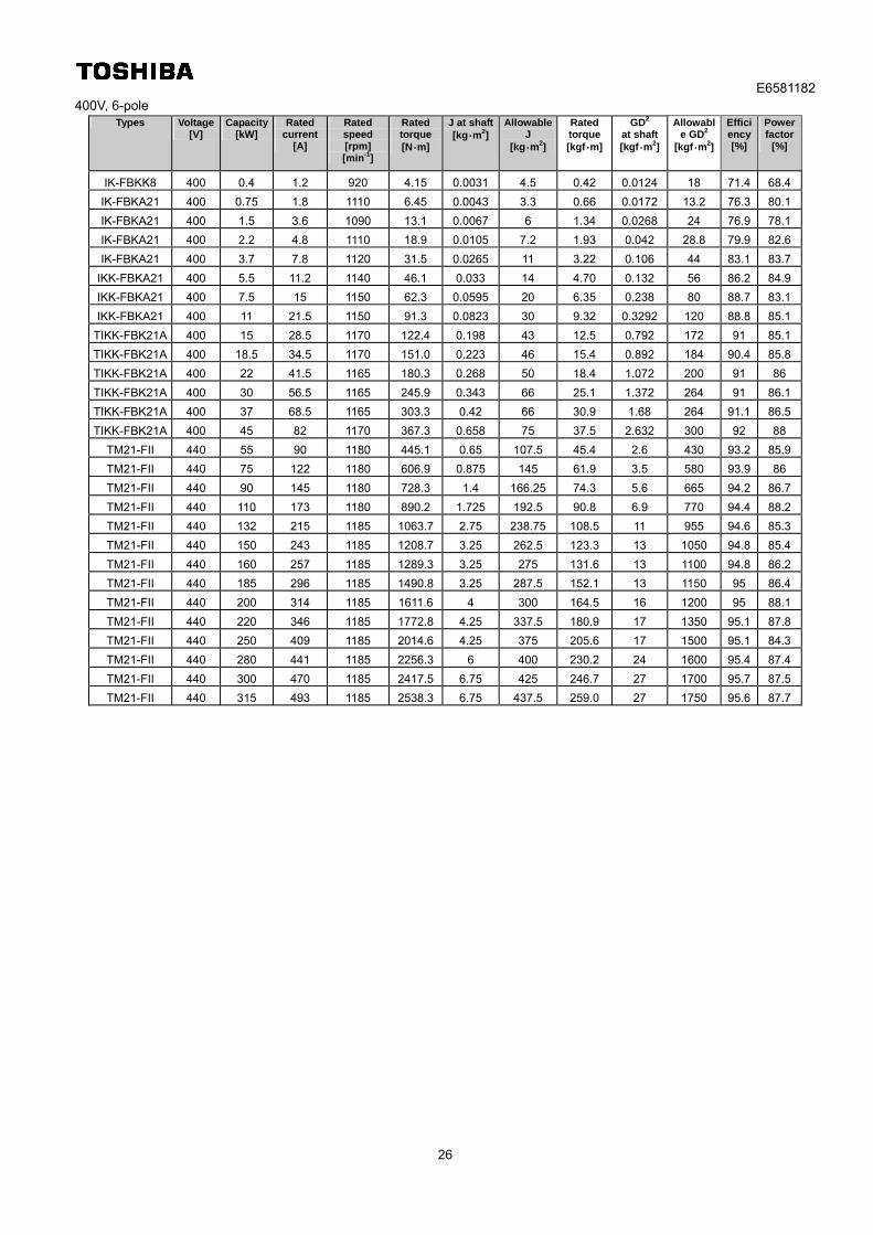
400V, 6-pole Types Voltage
[V] Capacity
[kW] Rated
current [A]
Rated speed [rpm] [min-1]
Rated torque[N・m]
J at shaft[kg・m2]
Allowable J
[kg・m2]
Rated torque[kgf・m]
GD2 at shaft
[kgf・m2]
Allowable GD2
[kgf・m2]
Efficiency [%]
Power factor
[%]
IK-FBKK8 400 0.4 1.2 920 4.15 0.0031 4.5 0.42 0.0124 18 71.4 68.4
IK-FBKA21 400 0.75 1.8 1110 6.45 0.0043 3.3 0.66 0.0172 13.2 76.3 80.1
IK-FBKA21 400 1.5 3.6 1090 13.1 0.0067 6 1.34 0.0268 24 76.9 78.1
IK-FBKA21 400 2.2 4.8 1110 18.9 0.0105 7.2 1.93 0.042 28.8 79.9 82.6
IK-FBKA21 400 3.7 7.8 1120 31.5 0.0265 11 3.22 0.106 44 83.1 83.7
IKK-FBKA21 400 5.5 11.2 1140 46.1 0.033 14 4.70 0.132 56 86.2 84.9
IKK-FBKA21 400 7.5 15 1150 62.3 0.0595 20 6.35 0.238 80 88.7 83.1
IKK-FBKA21 400 11 21.5 1150 91.3 0.0823 30 9.32 0.3292 120 88.8 85.1
TIKK-FBK21A 400 15 28.5 1170 122.4 0.198 43 12.5 0.792 172 91 85.1
TIKK-FBK21A 400 18.5 34.5 1170 151.0 0.223 46 15.4 0.892 184 90.4 85.8
TIKK-FBK21A 400 22 41.5 1165 180.3 0.268 50 18.4 1.072 200 91 86
TIKK-FBK21A 400 30 56.5 1165 245.9 0.343 66 25.1 1.372 264 91 86.1
TIKK-FBK21A 400 37 68.5 1165 303.3 0.42 66 30.9 1.68 264 91.1 86.5
TIKK-FBK21A 400 45 82 1170 367.3 0.658 75 37.5 2.632 300 92 88
TM21-FII 440 55 90 1180 445.1 0.65 107.5 45.4 2.6 430 93.2 85.9
TM21-FII 440 75 122 1180 606.9 0.875 145 61.9 3.5 580 93.9 86
TM21-FII 440 90 145 1180 728.3 1.4 166.25 74.3 5.6 665 94.2 86.7
TM21-FII 440 110 173 1180 890.2 1.725 192.5 90.8 6.9 770 94.4 88.2
TM21-FII 440 132 215 1185 1063.7 2.75 238.75 108.5 11 955 94.6 85.3
TM21-FII 440 150 243 1185 1208.7 3.25 262.5 123.3 13 1050 94.8 85.4
TM21-FII 440 160 257 1185 1289.3 3.25 275 131.6 13 1100 94.8 86.2
TM21-FII 440 185 296 1185 1490.8 3.25 287.5 152.1 13 1150 95 86.4
TM21-FII 440 200 314 1185 1611.6 4 300 164.5 16 1200 95 88.1
TM21-FII 440 220 346 1185 1772.8 4.25 337.5 180.9 17 1350 95.1 87.8
TM21-FII 440 250 409 1185 2014.6 4.25 375 205.6 17 1500 95.1 84.3
TM21-FII 440 280 441 1185 2256.3 6 400 230.2 24 1600 95.4 87.4
TM21-FII 440 300 470 1185 2417.5 6.75 425 246.7 27 1700 95.7 87.5
TM21-FII 440 315 493 1185 2538.3 6.75 437.5 259.0 27 1750 95.6 87.7

E6581182
27
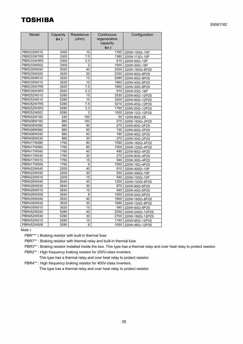
Appendix 2: List of braking resistors
Model Capacity
(W) Resistance
(ohm) Continuous regenerative
capacity (W)
Configuration
PBR-2007 120 200 90 120W-200Ω PBR-2022 120 75 90 120W-75Ω PBR-2037 120 40 90 120W-40Ω PBR-4037 120 160 90 120W-160Ω
PBR7-004W060 440 60 130 440W-60Ω
PBR7-004W015 440 15 130 440W-15Ω PBR7-008W060 880 60 270 880W-60Ω PBR7-008W040 880 40 270 880W-40Ω PBR7-008W030 880 30 270 880W-30Ω PBR7-008W015 880 15 270 880W-15Ω PBR7-008W010 880 10 270 880W-10Ω PBR7-008W7R5 880 7.5 270 880W-7.5Ω PBR7-017W060 1760 60 540 1760W-60Ω PBR7-017W040 1760 40 540 1760W-40Ω PBR7-017W030 1760 30 540 1760W-30Ω PBR7-017W020 1760 20 540 1760W-20Ω PBR7-017W015 1760 15 540 1760W-15Ω PBR7-017W010 1760 10 540 1760W-10Ω PBR7-017W7R5 1760 7.5 540 1760W-7.5Ω PBR7-017W005 1760 5 540 1760W-5Ω PBR7-017W3R7 1760 3.75 540 1760W-3.75Ω PBR7-035W060 3520 60 1080 3520W-60Ω PBR7-035W040 3520 40 1080 3520W-40Ω PBR7-035W030 3520 30 1080 3520W-30Ω PBR7-035W020 3520 20 1080 3520W-20Ω PBR7-035W015 3520 15 1080 3520W-15Ω PBR7-035W010 3520 10 1080 3520W-10Ω PBR7-035W7R5 3520 7.5 1080 3520W-7.5Ω PBR7-035W005 3520 5 1080 3520W-5Ω PBR7-035W3R7 3520 3.75 1080 3520W-3.75Ω PBR7-035W2R5 3520 2.5 1080 3520W-2.5Ω PBR7-035W1R8 3520 1.87 1080 3520W-1.87Ω PBR7-052W060 5280 60 1620 5280W-60Ω PBR7-052W040 5280 40 1620 5280W-40Ω PBR7-052W030 5280 30 1620 5280W-30Ω PBR7-052W020 5280 20 1620 5280W-20Ω PBR7-052W015 5280 15 1620 5280W-15Ω PBR7-052W010 5280 10 1620 5280W-10Ω PBR7-052W7R5 5280 7.5 1620 5280W-7.5Ω PBR7-052W005 5280 5 1620 5280W-5Ω PBR7-052W3R7 5280 3.75 1620 5280W-3.75Ω PBR7-052W2R5 5280 2.5 1620 5280W-2.5Ω PBR7-052W1R8 5280 1.87 1620 5280W-1.87Ω PBR7-052W1R2 5280 1.25 1620 5280W-1.25Ω
PBR3-2055 240 20 96 120W-40Ω2P PBR3-2075 440 15 130 220W-30Ω2P PBR3-2110 660 10 200 220W-30Ω3P PBR3-2150 880 7.5 270 220W-30Ω4P PBR3-2220 1760 3.3 610 220W-27Ω8P PBR3-4037 120 160 50 120W-160Ω PBR3-4055 240 80 96 120W-160Ω2P PBR3-4075 440 60 130 220W-120Ω2P PBR3-4110 660 40 190 220W-120Ω3P PBR3-4150 880 30 270 220W-120Ω4P PBR3-4220 1760 15 540 220W-30Ω4P2S
E6581182
28
Model Capacity
(W) Resistance
(ohm) Continuous regenerative
capacity (W)
Configuration
PBR233W010 3300 10 1760 220W-150Ω15P PBR233W7R5 3300 7.5 1380 220W-113Ω15P PBR233W3R3 3300 3.3 610 220W-50Ω15P PBR233W002 3300 2 1000 220W-30Ω15P PBR235W040 3520 40 2250 220W-160Ω8P2S PBR235W020 3520 20 2330 220W-80Ω8P2S PBR235W015 3520 15 2080 220W-60Ω8P2S PBR235W010 3520 10 1960 220W-40Ω8P2S PBR235W7R5 3520 7.5 1660 220W-30Ω8P2S PBR235W3R3 3520 3.3 610 220W-53Ω16P PBR252W015 5280 15 3330 220W-90Ω12P2S PBR252W010 5280 10 3200 220W-60Ω12P2S PBR252W7R5 5280 7.5 3210 220W-45Ω12P2S PBR252W3R3 5280 3.3 1760 220W-20Ω12P2S PBR252W002 5280 2 1000 220W-12Ω12P2S PBR402W160 240 160 50 120W-80Ω2S PBR408W160 880 160 570 220W-160Ω2P2S PBR408W080 880 80 270 220W-80Ω2P2S PBR408W060 880 60 130 220W-60Ω2P2S PBR408W040 880 40 190 220W-40Ω2P2S PBR408W030 880 30 270 220W-30Ω2P2S PBR417W080 1760 80 1090 220W-160Ω4P2S PBR417W060 1760 60 1000 220W-120Ω4P2S PBR417W040 1760 40 490 220W-80Ω4P2S PBR417W030 1760 30 270 220W-80Ω4P2S PBR417W015 1760 15 540 220W-30Ω4P2S PBR417W008 1760 8 1000 220W-16Ω4P2S PBR422W040 2200 40 810 220W-400Ω10P PBR422W030 2200 30 550 220W-300Ω10P PBR422W015 2200 15 540 220W-150Ω10P PBR426W040 2640 40 1250 220W-120Ω6P2S PBR426W030 2640 30 870 220W-90Ω6P2S PBR426W015 2640 15 540 220W-45Ω6P2S PBR426W008 2640 8 1000 220W-24Ω6P2S PBR435W040 3520 40 1900 220W-160Ω8P2S PBR435W030 3520 30 1680 220W-120Ω8P2S PBR435W015 3520 15 540 220W-60Ω8P2S PBR452W040 5280 40 2250 220W-240Ω12P2S PBR452W030 5280 30 2700 220W-180Ω12P2S PBR452W015 5280 15 1740 220W-90Ω12P2S PBR452W008 5280 8 1000 220W-48Ω12P2S
Note:
PBR***:Braking resistor with built-in thermal fuse
PBR7** : Braking resistor with thermal relay and built-in thermal fuse
PBR3** : Braking resistor installed inside the box. This type has a thermal relay and over heat relay to protect resistor.
PBR2** : High frequency braking resistor for 200V-class inverters.
This type has a thermal relay and over heat relay to protect resistor.
PBR4** : High frequency braking resistor for 400V-class inverters.
This type has a thermal relay and over heat relay to protect resistor.
E6581182
29
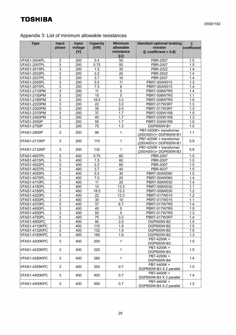
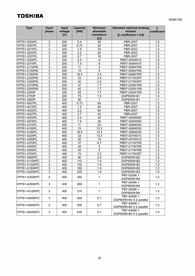
Appendix 3: List of minimum allowable resistances
Type Input phase
Input voltage
[V]
Capacity[kW]
Minimum allowable resistance
[]
Standard optional braking resistor
( coefficient = 0.8)
coefficient
VFAS1-2004PL 3 200 0.4 50 PBR-2007 1.5 VFAS1-2007PL 3 200 0.75 50 PBR-2007 1.5 VFAS1-2015PL 3 200 1.5 35 PBR-2022 1.4 VFAS1-2022PL 3 200 2.2 20 PBR-2022 1.4 VFAS1-2037PL 3 200 3.7 16 PBR-2037 1.4 VFAS1-2055PL 3 200 5.5 11 PBR7-004W015 1.3 VFAS1-2075PL 3 200 7.5 8 PBR7-004W015 1.4 VFAS1-2110PM 3 200 11 5 PBR7-008W7R5 1.4 VFAS1-2150PM 3 200 15 5 PBR7-008W7R5 1.1 VFAS1-2185PM 3 200 18.5 3.3 PBR7-008W7R5 1.0 VFAS1-2220PM 3 200 22 3.3 PBR7-017W3R7 1.3 VFAS1-2300PM 3 200 30 2.5 PBR7-017W3R7 1.3 VFAS1-2370PM 3 200 37 1.7 PBR7-035W1R8 1.5 VFAS1-2450PM 3 200 45 1.7 PBR7-035W1R8 1.3 VFAS1-2550P 3 200 55 1.7 PBR7-035W1R8 1.0 VFAS1-2750P 3 200 75 1.3 DGP600W-B1 1.0
VFAS1-2900P 3 200 90 1 PB7-4200K+ transformer
(200/400V)+ DGP600W-B1 1.1
VFAS1-2110KP 3 200 110 1 PB7-4200K + transformer
(200/400V)+ DGP600W-B1 0.9
VFAS1-2132KP 3 200 132 1 PB7-4200K + transformer
(200/400V)+ DGP600W-B3 0.8
VFAS1-4007PL 3 400 0.75 60 PBR-2007 1.5 VFAS1-4015PL 3 400 1.5 60 PBR-2007 1.5 VFAS1-4022PL 3 400 2.2 60 PBR-2007 1.5 VFAS1-4037PL 3 400 3.7 40 PBR-4037 1.5 VFAS1-4055PL 3 400 5.5 30 PBR7-004W060 1.5 VFAS1-4075PL 3 400 7.5 20 PBR7-004W060 1.4 VFAS1-4110PL 3 400 11 20 PBR7-008W030 1.4 VFAS1-4150PL 3 400 15 13.3 PBR7-008W030 1.1 VFAS1-4185PL 3 400 18.5 13.3 PBR7-008W030 1.2 VFAS1-4220PL 3 400 22 13.3 PBR7-017W015 1.2 VFAS1-4300PL 3 400 30 10 PBR7-017W015 1.1 VFAS1-4370PL 3 400 37 6.7 PBR7-017W7R5 1.4 VFAS1-4450PL 3 400 45 5 PBR7-017W7R5 1.5 VFAS1-4550PL 3 400 55 5 PBR7-017W7R5 1.3 VFAS1-4750PL 3 400 75 3.3 PBR7-017W3R7 1.4 VFAS1-4900PC 3 400 90 2.5 DGP600W-B2 1.5 VFAS1-4110KPC 3 400 110 1.9 DGP600W-B2 1.5 VFAS1-4132KPC 3 400 132 1.9 DGP600W-B2 1.5 VFAS1-4160KPC 3 400 160 1.9 DGP600W-B2 1.3
VFAS1-4200KPC 3 400 200 1 PB7-4200K + DGP600W-B3
1.5
VFAS1-4220KPC 3 400 220 1 PB7-4200K + DGP600W-B3
1.5
VFAS1-4280KPC 3 400 280 1 PB7-4200K + DGP600W-B4
1.4
VFAS1-4355KPC 3 400 355 0.7 PB7-4400K +
DGP600W-B3 X 2 parallel 1.5
VFAS1-4400KPC 3 400 400 0.7 PB7-4400K +
DGP600W-B3 X 2 parallel 1.4
VFAS1-4500KPC 3 400 500 0.7 PB7-4400K +
DGP600W-B4 X 2 parallel 1.2
E6581182
30
Type Input phase
Input voltage
[V]
Capacity[kW]
Minimum allowable resistance
[]
Standard optional braking resistor
( coefficient = 0.8)
coefficient
VFPS1-2004PL 3 200 0.4 50 PBR-2007 1.2 VFPS1-2007PL 3 200 0.75 50 PBR-2007 1.2 VFPS1-2015PL 3 200 1.5 35 PBR-2022 1.2 VFPS1-2022PL 3 200 2.2 20 PBR-2022 1.2 VFPS1-2037PL 3 200 3.7 16 PBR-2037 1.2 VFPS1-2055PL 3 200 5.5 11 PBR7-004W015 1.2 VFPS1-2075PL 3 200 7.5 8 PBR7-004W015 1.2 VFPS1-2110PM 3 200 11 5 PBR7-008W7R5 1.2 VFPS1-2150PM 3 200 15 5 PBR7-008W7R5 1.1 VFPS1-2185PM 3 200 18.5 3.3 PBR7-008W7R5 1.2 VFPS1-2220PM 3 200 22 3.3 PBR7-017W3R7 1.2 VFPS1-2300PM 3 200 30 2.5 PBR7-017W3R7 1.2 VFPS1-2370PM 3 200 37 1.7 PBR7-035W1R8 1.2 VFPS1-2450PM 3 200 45 1.7 PBR7-035W1R8 1.2 VFPS1-2550P 3 200 55 1.7 PBR7-035W1R8 1.0 VFPS1-2750P 3 200 75 1.3 DGP600W-B1 1.0 VFPS1-2900P 3 200 90 1 DGP600W-B1 1.1 VFPS1-4007PL 3 400 0.75 60 PBR-2007 1.2 VFPS1-4015PL 3 400 1.5 60 PBR-2007 1.2 VFPS1-4022PL 3 400 2.2 60 PBR-2007 1.2 VFPS1-4037PL 3 400 3.7 40 PBR-4037 1.2 VFPS1-4055PL 3 400 5.5 30 PBR7-004W060 1.2 VFPS1-4075PL 3 400 7.5 20 PBR7-004W060 1.2 VFPS1-4110PL 3 400 11 20 PBR7-008W030 1.2 VFPS1-4150PL 3 400 15 13.3 PBR7-008W030 1.2 VFPS1-4185PL 3 400 18.5 13.3 PBR7-008W030 1.2 VFPS1-4220PL 3 400 22 13.3 PBR7-007W015 1.2 VFPS1-4300PL 3 400 30 10 PBR7-007W015 1.1 VFPS1-4370PL 3 400 37 6.7 PBR7-017W7R5 1.2 VFPS1-4450PL 3 400 45 5 PBR7-017W7R5 1.2 VFPS1-4550PL 3 400 55 5 PBR7-017W7R5 1.2 VFPS1-4750PL 3 400 75 3.3 PBR7-017W3R7 1.2 VFPS1-4900PC 3 400 90 2.5 DGP600W-B2 1.2 VFPS1-4110KPC 3 400 110 1.9 DGP600W-B2 1.2 VFPS1-4132KPC 3 400 132 1.9 DGP600W-B2 1.2 VFPS1-4160KPC 3 400 160 1.9 DGP600W-B2 1.2 VFPS1-4220KPC 3 400 220 1.9 DGP600W-B3 1.0
VFPS1-4250KPC 3 400 250 1 PB7-4200K + DGP600W-B4
1.2
VFPS1-4280KPC 3 400 280 1 PB7-4200K + DGP600W-B4
1.2
VFPS1-4315KPC 3 400 315 1 PB7-4200K + DGP600W-B4
1.2
VFPS1-4400KPC 3 400 400 0.7 PB7-4400K +
DGP600W-B3 X 2 parallel 1.2
VFPS1-4500KPC 3 400 500 0.7 PB7-4400K +
DGP600W-B4 X 2 parallel 1.2
VFPS1-4630KPC 3 400 630 0.7 PB7-4400K +
DGP600W-B4 X 2 parallel 1.0
E6581182
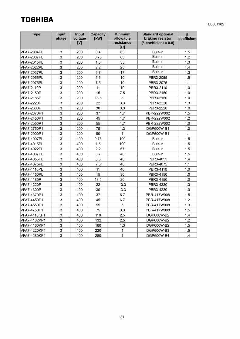
31
Type Input phase
Input voltage
[V]
Capacity[kW]
Minimum allowable resistance
[]
Standard optional braking resistor
( coefficient = 0.8)
coefficient
VFA7-2004PL 3 200 0.4 63 Built-in 1.5
VFA7-2007PL 3 200 0.75 63 Built-in 1.2
VFA7-2015PL 3 200 1.5 35 Built-in 1.3
VFA7-2022PL 3 200 2.2 25 Built-in 1.4
VFA7-2037PL 3 200 3.7 17 Built-in 1.3
VFA7-2055PL 3 200 5.5 10 PBR3-2055 1.5
VFA7-2075PL 3 200 7.5 10 PBR3-2075 1.1
VFA7-2110P 3 200 11 10 PBR3-2110 1.0
VFA7-2150P 3 200 15 7.5 PBR3-2150 1.0
VFA7-2185P 3 200 18.5 5 PBR3-2150 1.0
VFA7-2220P 3 200 22 3.3 PBR3-2220 1.3
VFA7-2300P 3 200 30 3.3 PBR3-2220 1.0
VFA7-2370P1 3 200 37 1.7 PBR-222W002 1.5
VFA7-2450P1 3 200 45 1.7 PBR-222W002 1.2
VFA7-2550P1 3 200 55 1.7 PBR-222W002 1.0
VFA7-2750P1 3 200 75 1.3 DGP600W-B1 1.0
VFA7-2900P1 3 200 90 1 DGP600W-B1 1.1
VFA7-4007PL 3 400 0.75 100 Built-in 1.5
VFA7-4015PL 3 400 1.5 100 Built-in 1.5
VFA7-4022PL 3 400 2.2 67 Built-in 1.5
VFA7-4037PL 3 400 3.7 40 Built-in 1.5
VFA7-4055PL 3 400 5.5 40 PBR3-4055 1.4
VFA7-4075PL 3 400 7.5 40 PBR3-4075 1.1
VFA7-4110PL 3 400 11 40 PBR3-4110 1.0
VFA7-4150PL 3 400 15 30 PBR3-4150 1.0
VFA7-4185P 3 400 18.5 20 PBR3-4150 1.0
VFA7-4220P 3 400 22 13.3 PBR3-4220 1.3
VFA7-4300P 3 400 30 13.3 PBR3-4220 1.0
VFA7-4370P1 3 400 37 6.7 PBR-417W008 1.5
VFA7-4450P1 3 400 45 6.7 PBR-417W008 1.2
VFA7-4550P1 3 400 55 5 PBR-417W008 1.3
VFA7-4750P1 3 400 75 3.3 PBR-417W008 1.5
VFA7-4110KP1 3 400 110 2.5 DGP600W-B2 1.4
VFA7-4132KP1 3 400 132 2.5 DGP600W-B2 1.2
VFA7-4160KP1 3 400 160 1.3 DGP600W-B2 1.5
VFA7-4220KP1 3 400 220 1 DGP600W-B3 1.5
VFA7-4280KP1 3 400 280 1 DGP600W-B4 1.4
E6581182
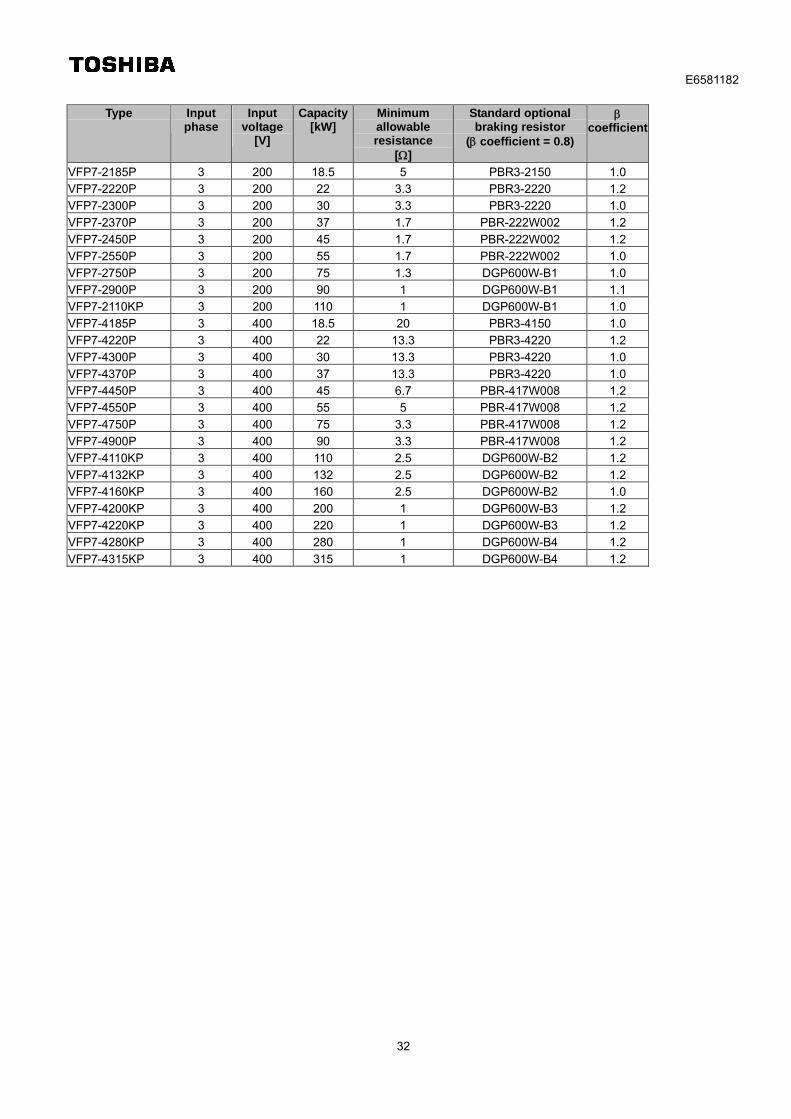
32
Type Input
phase Input
voltage [V]
Capacity[kW]
Minimum allowable resistance
[]
Standard optional braking resistor
( coefficient = 0.8)
coefficient
VFP7-2185P 3 200 18.5 5 PBR3-2150 1.0
VFP7-2220P 3 200 22 3.3 PBR3-2220 1.2
VFP7-2300P 3 200 30 3.3 PBR3-2220 1.0
VFP7-2370P 3 200 37 1.7 PBR-222W002 1.2
VFP7-2450P 3 200 45 1.7 PBR-222W002 1.2
VFP7-2550P 3 200 55 1.7 PBR-222W002 1.0
VFP7-2750P 3 200 75 1.3 DGP600W-B1 1.0
VFP7-2900P 3 200 90 1 DGP600W-B1 1.1
VFP7-2110KP 3 200 110 1 DGP600W-B1 1.0
VFP7-4185P 3 400 18.5 20 PBR3-4150 1.0
VFP7-4220P 3 400 22 13.3 PBR3-4220 1.2
VFP7-4300P 3 400 30 13.3 PBR3-4220 1.0
VFP7-4370P 3 400 37 13.3 PBR3-4220 1.0
VFP7-4450P 3 400 45 6.7 PBR-417W008 1.2
VFP7-4550P 3 400 55 5 PBR-417W008 1.2
VFP7-4750P 3 400 75 3.3 PBR-417W008 1.2
VFP7-4900P 3 400 90 3.3 PBR-417W008 1.2
VFP7-4110KP 3 400 110 2.5 DGP600W-B2 1.2
VFP7-4132KP 3 400 132 2.5 DGP600W-B2 1.2
VFP7-4160KP 3 400 160 2.5 DGP600W-B2 1.0
VFP7-4200KP 3 400 200 1 DGP600W-B3 1.2
VFP7-4220KP 3 400 220 1 DGP600W-B3 1.2
VFP7-4280KP 3 400 280 1 DGP600W-B4 1.2
VFP7-4315KP 3 400 315 1 DGP600W-B4 1.2
E6581182
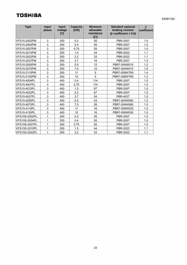
33
Type Input
phase Input
voltage [V]
Capacity[kW]
Minimum allowable resistance
[]
Standard optional braking resistor
( coefficient = 0.8)
coefficient
VFS15-2002PM 3 200 0.2 55 PBR-2007 1.5
VFS15-2004PM 3 200 0.4 55 PBR-2007 1.5
VFS15-2007PM 3 200 0.75 55 PBR-2007 1.5
VFS15-2015PM 3 200 1.5 44 PBR-2022 1.1
VFS15-2022PM 3 200 2.2 33 PBR-2022 1.1
VFS15-2037PM 3 200 3.7 16 PBR-2037 1.4
VFS15-2055PM 3 200 5.5 12 PBR7-004W015 1.2
VFS15-2075PM 3 200 7.5 12 PBR7-004W015 1.0
VFS15-2110PM 3 200 11 5 PBR7-008W7R5 1.4
VFS15-2150PM 3 200 15 5 PBR7-008W7R5 1.2
VFS15-4004PL 3 400 0.4 114 PBR-2007 1.5
VFS15-4007PL 3 400 0.75 114 PBR-2007 1.5
VFS15-4015PL 3 400 1.5 67 PBR-2007 1.5
VFS15-4022PL 3 400 2.2 67 PBR-2007 1.5
VFS15-4037PL 3 400 3.7 54 PBR-4037 1.5
VFS15-4055PL 3 400 5.5 43 PBR7-004W060 1.3
VFS15-4075PL 3 400 7.5 28 PBR7-004W060 1.5
VFS15-4110PL 3 400 11 16 PBR7-008W030 1.5
VFS15-4150PL 3 400 15 16 PBR7-008W030 1.5
VFS15S-2002PL 1 200 0.2 55 PBR-2007 1.5
VFS15S-2004PL 1 200 0.4 55 PBR-2007 1.5
VFS15S-2007PL 1 200 0.75 55 PBR-2007 1.5
VFS15S-2015PL 1 200 1.5 44 PBR-2022 1.1
VFS15S-2022PL 1 200 2.2 33 PBR-2022 1.1
E6581182
34
Type Input
phase Input
voltage [V]
Capacity[kW]
Minimum allowable resistance
[]
Standard optional braking resistor
( coefficient = 0.8)
coefficient
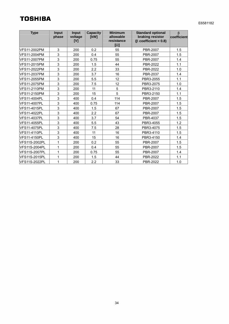
VFS11-2002PM 3 200 0.2 55 PBR-2007 1.5
VFS11-2004PM 3 200 0.4 55 PBR-2007 1.5
VFS11-2007PM 3 200 0.75 55 PBR-2007 1.4
VFS11-2015PM 3 200 1.5 44 PBR-2022 1.1
VFS11-2022PM 3 200 2.2 33 PBR-2022 1.0
VFS11-2037PM 3 200 3.7 16 PBR-2037 1.4
VFS11-2055PM 3 200 5.5 12 PBR3-2055 1.1
VFS11-2075PM 3 200 7.5 12 PBR3-2075 1.0
VFS11-2110PM 3 200 11 5 PBR3-2110 1.4
VFS11-2150PM 3 200 15 5 PBR3-2150 1.1
VFS11-4004PL 3 400 0.4 114 PBR-2007 1.5
VFS11-4007PL 3 400 0.75 114 PBR-2007 1.5
VFS11-4015PL 3 400 1.5 67 PBR-2007 1.5
VFS11-4022PL 3 400 2.2 67 PBR-2007 1.5
VFS11-4037PL 3 400 3.7 54 PBR-4037 1.5
VFS11-4055PL 3 400 5.5 43 PBR3-4055 1.2
VFS11-4075PL 3 400 7.5 28 PBR3-4075 1.5
VFS11-4110PL 3 400 11 16 PBR3-4110 1.5
VFS11-4150PL 3 400 15 16 PBR3-4150 1.4
VFS11S-2002PL 1 200 0.2 55 PBR-2007 1.5
VFS11S-2004PL 1 200 0.4 55 PBR-2007 1.5
VFS11S-2007PL 1 200 0.75 55 PBR-2007 1.4
VFS11S-2015PL 1 200 1.5 44 PBR-2022 1.1
VFS11S-2022PL 1 200 2.2 33 PBR-2022 1.0
E6581182
35
Type Input
phase Input
voltage [V]
Capacity[kW]
Minimum allowable resistance
[]
Standard optional braking resistor
( coefficient = 0.8)
coefficient
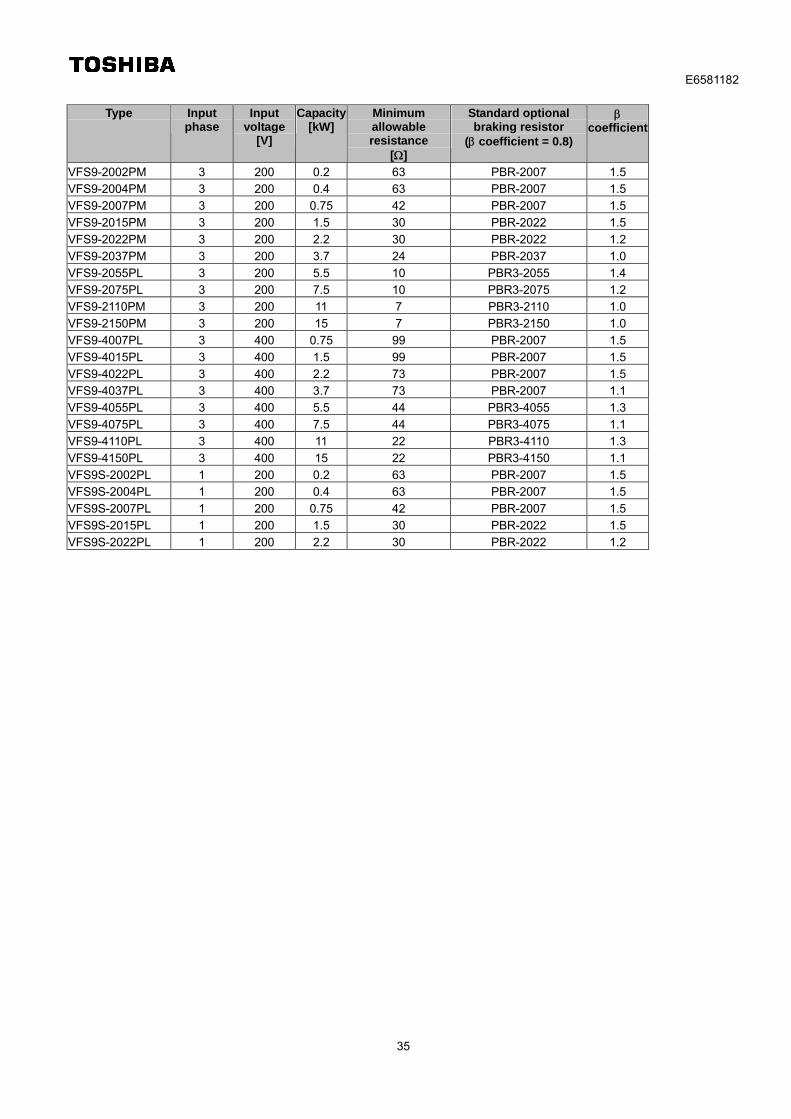
VFS9-2002PM 3 200 0.2 63 PBR-2007 1.5
VFS9-2004PM 3 200 0.4 63 PBR-2007 1.5
VFS9-2007PM 3 200 0.75 42 PBR-2007 1.5
VFS9-2015PM 3 200 1.5 30 PBR-2022 1.5
VFS9-2022PM 3 200 2.2 30 PBR-2022 1.2
VFS9-2037PM 3 200 3.7 24 PBR-2037 1.0
VFS9-2055PL 3 200 5.5 10 PBR3-2055 1.4
VFS9-2075PL 3 200 7.5 10 PBR3-2075 1.2
VFS9-2110PM 3 200 11 7 PBR3-2110 1.0
VFS9-2150PM 3 200 15 7 PBR3-2150 1.0
VFS9-4007PL 3 400 0.75 99 PBR-2007 1.5
VFS9-4015PL 3 400 1.5 99 PBR-2007 1.5
VFS9-4022PL 3 400 2.2 73 PBR-2007 1.5
VFS9-4037PL 3 400 3.7 73 PBR-2007 1.1
VFS9-4055PL 3 400 5.5 44 PBR3-4055 1.3
VFS9-4075PL 3 400 7.5 44 PBR3-4075 1.1
VFS9-4110PL 3 400 11 22 PBR3-4110 1.3
VFS9-4150PL 3 400 15 22 PBR3-4150 1.1
VFS9S-2002PL 1 200 0.2 63 PBR-2007 1.5
VFS9S-2004PL 1 200 0.4 63 PBR-2007 1.5
VFS9S-2007PL 1 200 0.75 42 PBR-2007 1.5
VFS9S-2015PL 1 200 1.5 30 PBR-2022 1.5
VFS9S-2022PL 1 200 2.2 30 PBR-2022 1.2
E6581182
36
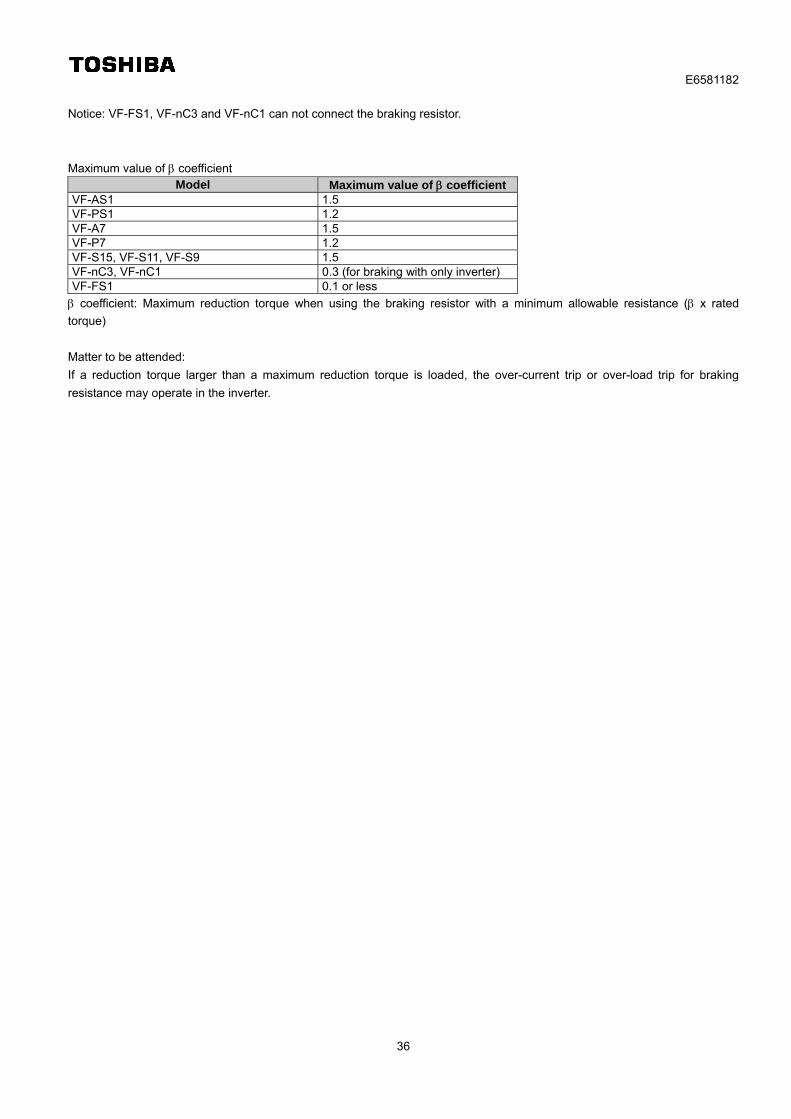
Notice: VF-FS1, VF-nC3 and VF-nC1 can not connect the braking resistor.
Maximum value of coefficient Model Maximum value of coefficient
VF-AS1 1.5 VF-PS1 1.2 VF-A7 1.5 VF-P7 1.2 VF-S15, VF-S11, VF-S9 1.5 VF-nC3, VF-nC1 0.3 (for braking with only inverter) VF-FS1 0.1 or less
coefficient: Maximum reduction torque when using the braking resistor with a minimum allowable resistance ( x rated
torque)
Matter to be attended:
If a reduction torque larger than a maximum reduction torque is loaded, the over-current trip or over-load trip for braking
resistance may operate in the inverter.