abolishing the wave-particle duality nonsense - blaze labsblazelabs.com/abolishing_duality.pdf ·...
TRANSCRIPT

1
Abolishing the wave-particle duality nonsense © Engineer Xavier Borg - Blaze Labs
Published 9/9/2010 Web: www.blazelabs.com Email: [email protected] In this paper I shall describe how waves account for their particulate nature, without the requirement for any particles to be involved. Using geometry and known facts about electromagnetic radiation we shall explore the truth behind the ghost particle otherwise known as the photon and hence the true nature of light. The debate over the true nature of light dates back to the 1600s. Christiaan Huygens proposed light to be waves, whilst Isaac Newton came up with his own corpuscles (particles) theory. Over periods of time, preference flipped to and fro between these two opposing views. Presently, the scientific community cannot find a proper resolution to this debate and it holds that all waves also have a particle nature (and vice versa).
Light: Particle or wave? In 1905 Einstein published his light quanta hypothesis, in a tentative to describe light quanta as particles. Yet, after over 45 years of struggle with its refusal from prominent scientists and his own persistent dwelling with this idea, he gave up hope of, either himself or anybody else, finding the truth about the nature of light. Just a few years before his death, we can clearly see his frustration from the following comments: "All my attempts to adapt the theoretical foundation of physics to this new type of knowledge (Quantum Theory) failed completely. It was as if the ground had been pulled out from under one, with no firm foundation to be seen
anywhere, upon which one could have built." -Albert Einstein 1949
"All these fifty years of conscious brooding have brought me no nearer to the answer to the question 'What are light quanta?'
Nowadays every Tom, Dick and Harry thinks he knows it, but he is mistaken" - A. Einstein, 1951 Sixty more years have passed, theories have been revised and updated, new technologies have surfaced, and yet it seems that nobody has had the guts to tackle this challenging issue again. Scientists seem satisfied enough reciting the wave-particle duality. So, shall all we do the same and accept this paradox as part of science, just because Einstein failed and gave up! How can we know whether our source is sending out matter or waves? Well, no matter can travel at the speed of light, but waves can. So, theoretically, this question can be answered by simply measuring the speed of the flying entity. Also, if one sends out a wave, it ripples across space with a spherical wave front, so its intensity at the detector would be inversely proportional to the distance travelled squared. On the other hand, if one throws out a particle of matter, it would be expected that even if it is too small to be seen, the momentum exchanged at the target would be the same or very close to the momentum gained as it left the source. However, detecting momentum does not tell us if the thing which hit our target is a wave or a particle, since a particle would have momentum of magnitude p=m*v due to its mass being in motion, and a wave would have momentum due to its Poynting vector (the cross product of the E-field and B-field vectors) of magnitude p=E/c. Light offers a challenge to the scientist because its properties are neither fully described by an all particle model, nor by an all wave model; or are they? The problem with light and other high frequency radiation is that momentum of individual packets does not spread out, so it seems to behave like matter or waves which are contained in some special container to keep them from spreading out. But all matter has mass, so this would restrict light to a speed below that of light itself. For this reason, a special fictitious, force carrying particle - the photon - was hypothesized, and declared to have zero mass. To date, not a single photon has ever been detected during its flight. Detection of photons is always a result of energy/momentum exchange at the target location. We have absolutely no experimental evidence to prove their propagating ability. Light also shows interference, diffraction, refraction, and all other classic wave properties, which matter doesn't show, so in these cases we would have to revert to light as classical EM waves - the concept of duality.

2
In practice, not all EM waves are known to behave as particles. Radio waves never seem to show particle behaviour, or wave collapse, while visible light, which is so close to radio in wavelength, is said to show particulate behaviour. Some think that the reason for this is because radio photons would be ridiculously large, others think that there must be some frequency at which photons are not formed, some may have other theories and the majority have no clue at all. Validity of the Inverse Square Law (ISL) All EM waves should share similar properties, so why is this discrepancy in behaviour? This enigma is only sorted out if one goes into more detail on the propagation of EM waves and the properties of the SOURCE and/or target interacting with the radiation. Few are the people aware of the fact that different shapes of surface areas covered by the propagating wave front give different relationship of intensity with distance. Most people just recite the inverse square law for any problem involving the propagation of EM waves. However, few are those who understand that the inverse square law is simply a geometric law, and is not an inherent property of waves.
Fig.1 The geometric origin of the inverse square law
The inverse square relation of radiation intensity I with distance R is derived from the surface area of a sphere, since energy must be conserved from one spherical surface to the next. As one can easily understand from the above diagram, intensity from an isotropic source, radiating power P, is equal to the radiated power per unit surface area. Since the surface area of a sphere is given by A = 4 π R2, then the intensity I is given by: I=P/(4 π R2). The law is true as long as it is applied to the correct geometry. The inverse square law is only valid for a point source propagating spherical waves into space.

3
If we have a planewave, which keeps the same cross sectional area during propagation, then the inverse square law clearly no longer applies. In fact, the intensity of planewaves is invariant with distance. In general it can be stated that any source in which beam shaping takes place cannot comply with the basic ISL assumption. Shown below are just a few examples of common directional EM wave sources, for which the ISL cannot be applied directly.
Fig.2 A few examples of common directional electromagnetic radiators

4
Correct application of the inverse square law (ISL) to high gain EMR sources Planewave sources do NOT obey the inverse square law, for the simple reason that the propagating surface is no longer spherical. A square cross sectional area size 2x2cm will still have the same shape and size after travelling 1km. But how can one produce a planewave, if a simple isotropic radiator generates spherical waves? The answer is to modify the source so that it can no longer be modelled as a point source. This can be done by using many sources interacting together in a way to give a preferred beam direction and flatten out the curvature of the spherical surface enough for the resultant waves to share the most important properties of planewaves. I shall refer to these modified waves as quasi-planewaves. In such configuration, the sources need not be all active; they could be parasitic (passive) elements interacting with a single active source, as in TV antennas. Also, remember that a spherical wave looks like a planewave over a small area very distant from the source. The trick to generate a quasi-planewave, using just spherical wave sources, is thus to provide a fake (virtual) long distance focal point behind the aperture of the EM source. This way, the wave fronts would exit the physical aperture in a preferred direction and at a much reduced surface curvature. This is exactly what happens with high gain EM sources. With such a virtual point source, the source can no longer be modelled as a point source at the centre of the physical aperture location, since the equivalent point source can now be a kilometre behind the aperture! The distance of this virtual point from the physical aperture can be easily calculated knowing the aperture cross section and beamwidth (or gain).
Fig.3 The correct way to apply the inverse square law to directional sources
Applying the inverse square law to directional sources requires for the virtual distance to be included in the calculation. If one measures the intensity variation with distance from any such devices, a discrepancy from the inverse square law (with distance being measured from the physical device) would be evident from the readings. One can easily confirm this by plotting light intensity with distance from a flash light or a laser pointer. The higher the source gain, or the bigger the effective aperture relative to the wavelength, the further the virtual point source moves behind the physical source location and the flatter is the wavefront. Extremely high gain sources can be modelled as pure planewave emitters. The extent to which the wave shows its 'particle like' behaviour depends only on the gain of the source and the detector. The net gain of a system comprising both a directional source and a directional target is equal to the product of their individual gain values.

5
Also, polarization won't make any difference to the surface curvature or gain. Polarization affects only the kind of momentum the wave imparts on the target. Linear polarization imparts linear momentum, while circular polarization imparts angular momentum. Today, circularly polarized beams are called 'chiral photons'.
Fig.4: A virtual point source resulting in a quasi planewave at the target
Argument Logic Let's briefly go through the logic of my argument: Matter cannot travel at the speed of light. Particles' motion does not obey the ISL. Particles are defined in two groups: matter and force carriers. Particles do not show interference. Particles propagate their momentum p=mv (v < c) from one point to another without spreading out. 'Photons' travel at the speed of light in vacuum. 'Photons' do not obey the ISL. 'Photons' have no rest mass. 'Photons' carry energy and are force carriers. 'Photons' transfer momentum p=hf/c. 'Photons' show interference. Electromagnetic waves travel at the speed of light in vacuum. Electromagnetic waves have no rest mass. Electromagnetic waves show interference. Electromagnetic waves carry energy and momentum p = E/c = hf/c, they are force carriers. Spherical EM waves spread out their energy & momentum over an increasing spherical area. Spherical EM waves become close to planewaves only at very large distances, but still propagate spherically. Plane EM waves do not spread out, so they do not obey the ISL and show a packet-like behaviour. Plane EM waves travel at the speed of light. High gain emitters convert a spherical wave source(s) into a narrow beam, simulating a planewave. From the above statements, one can clearly understand that 'photons', and all other force carrier particles travelling at the speed of light, can be replaced in all statements by the term 'planewaves'. These waves can be generated by simply beam shaping a spherical wave source.

6
'Packet-like behaviour' of highly directional waves In order to understand how quasi-plane EM waves can show all properties of the classic photon, I shall give a simple numeric example. Let’s say we have to calculate the ratio of intensities at 2m to that at 1m from a highly directional source. If we neglect the fact that the source is directional, and simply treat it as a point source, we would work out the solution by applying the inverse square law, giving : I2/I1 = (R1/R2)2= (1/2)2 = 25% On the other hand, if we take into account the gain, then we first find the location of the virtual point source location. Knowing the divergence and effective aperture of the source is enough to get this value. For the sake of keeping the argument simple, let's assume we found the virtual point source to be located at 1000m behind the source. Now by applying the inverse square law at this point (ref Fig.5), we can work out the expected intensity ratio: I2/I1 = (R1/R2)2= [(f + d1)/(f + d2)] 2 = (1001/1002)2 = 99.8% This gives virtually the same intensity and momentum transfer at twice the distance from the source! The higher the gain, the smaller is the difference. You throw a packet of energy, and receive the same packet of energy! In the case of a simple parabolic reflector, its gain would increase with frequency, so the same parabolic reflector would generate a narrower beam for higher frequencies. This would make higher frequency waves show a stronger 'packet-like' behaviour than lower frequency waves. Using highly directional sources, we are therefore able to radiate a packet of electromagnetic momentum at the source, and receive virtually the same amount of momentum at the target, all at the speed of light! Does it sound like something familiar? So, as you see, a directional source is able to make the wave act more like a particle, without any physical particle or box to contain the wave. No box or packet is required because the beam is able to restrict its own path in space, yet the receiver virtually got the whole amount of energy that was sent by the transmitter without the need for the wavefront to ‘collapse’ as it has to do with the wave-particle duality concept. What’s more, it does not break any fundamental law by travelling at the speed of light, because that’s what EM waves are supposed to do. This abolishes the requirement for a special massless particle we are used to call the photon. Photons simply do not exist. Their behaviour can be fully explained in terms of quasi-planewaves as has been explained.

7
Intensity calculations for high gain radiators
Fig.5 Correct application of ISL to high gain EM radiators
Note that the isotropic source waves (blue) would eventually flatten out to a plane wavefront at large distances (see blue wavefronts at B), but still spread out spherically. The directional waves (red) are quasi-planewaves from the instant they exit the source (see red wave fronts at A) and the spreading out over distance is minimal. The larger 'f' or aperture, the less the wave front spreads out. Also note that the effective radiated power P from a directional source will be a factor of G higher than the equivalent isotropic radiated power, so P= G x Piso. The correct intensity for a high gain radiator of effective radiated power P is given by: I = P/4 π R2 ..... where R is the distance from the virtual source to target (R = f + d )
I = G Piso /[4 π (f + d )2] … Equation 1 – Modified ISL equation for directional sources
f is usually not known, but can easily be geometrically calculated from other known parameters, such as the effective aperture, gain, or beam divergence. Equation 1 can be rewritten in many other ways depending on which are the known parameters. For example, we can write f in terms of the divergence θ and the effective aperture area AEff as: f = √(AEff/ π)/TAN(θ/2) ..... Giving:
I = G Piso/[√(AEff/ π)/TAN(θ/2) + d]2 ..... Which for f>>d simplifies to:
I = G Piso / (4 π f 2) .... Intensity becomes distance invariant and gives the intensity for planewaves. Although equation 1 applies to all directional sources, its application to different sources involves some other calculations in order to find the distance f. For optical systems we usually know (or can easily measure) the beam divergence, whilst for aperture antennas we usually know the antenna gain. Once we find f, we simply plug the value in equation 1 to find the intensity at any distance from the source.

8
Application to optical systems Examples of high gain radiators in the optical band include lasers and reflectors such as flashlights, car headlights, etc... In such cases the distance from the physical aperture to the virtual point source is unknown and has to be found in order to calculate the light intensity vs distance. For lasers, the aperture diameter and divergence angle θ are usually supplied by the manufacturer. Otherwise, they can easily be found using the following method. In the diagram below, DA represents the physical source aperture diameter. DT represents the beam diameter at a target distance d from the aperture.
By simply measuring any two beam diameters located distance d apart, one can find the divergence angle (in radians) from simple geometry: Tan (θ/2) = (DT – DA)/2d ... so, Divergence θ = 2 Arctan [(DT – DA)/2d] Knowing the aperture diameter and divergence angle, the distance f to the virtual point source can be found, since: Tan (θ/2) = DA/2f …. So, f = DA/ (2 Tan (θ/2)) , for collimated light (using a lens or optical cavity), Tan (θ/2) ~ (θ/2), so f= DA /θ From the modified ISL equation, the light intensity at any distance d, is given by : I = G Piso /[4 π (f + d )2] , therefore we can write intensity I in terms of the known aperture diameter and divergence angle as: Ireflectors = G Piso /[4 π ( DA/ (2 Tan (θ/2)) + d )2] OR Icollimated = G Piso /[4 π (DA/ θ + d )2]
Example: Find the intensity ratio for d=2m and d=1m, for a collimated high power laser having aperture diameter 6mm, and divergence angle 1mrad. Equivalent point source position f= DA /θ = 0.006/0.001 = 6 meters behind the laser. I2m = G Piso /[4 π ( DA/ θ + d )2] = G Piso /[4 π ( 0.006/0.001 + 2)2] = G Piso/ 804.25 I1m = G Piso /[4 π ( DA/ θ + d )2] = G Piso /[4 π ( 0.006/0.001 + 1)2] = G Piso/ 615.75 So, the intensity ratio I2m/ I1m = 76.7% as compared to 25% for an isotropic light source.

9
Application to aperture antennas Aperture antennas, such as microwave dishes are high gain directional radiators. In such cases, f is usually unknown but can be found by knowing its diameter and operating frequency. In practice, an efficiency factor µ would make the effective antenna aperture area AEff somewhat smaller than its physical aperture, usually in the range 50-70%. Using the equations below, one may find the antenna gain in order to estimate the beamwidth θ and f. AEff = µAPh = µ π D2/4 ... APh = physical aperture area, µ = Efficiency ~70%, D= Aperture diameter Antenna efficiency µ is not due to a single factor, but accounts for several types of losses, including RF losses, mismatch losses, illumination efficiency, spillover (edge spilling and backlobes), and phase error losses. Here are the derivations for relations between gain, effective aperture area, beamwidth, and wavelength. Gain G = A[sphere] / A[eff] = 4 pi f2/ A [eff] A[eff] = xy = f Sin(θ) x f Sin (φ) ~ f2 (θ x φ) So, G = 4 π / (θφ) Assuming equal horizontal and vertical beamwidth (θ = φ), Gain G = 4 π / θ2, Beamwidth θ = √ (4 π /G)
Beamwidth is related to wavelength by: Beamwidth θ = λ/√ Aeff , so, G = 4 π Aeff/λ2 We can rewrite equation 1 in terms of wavelength and beamwidth as: I = G Piso /[ (λ / θ) √(1/ π)/TAN (θ/2) + d]2
Or in terms of wavelength and gain as: I = G Piso /[ (λ / √ (4 /G))/TAN (√ (4 π /2G) + d]2
So, for aperture antennas, one may note that: Doubling the frequency, quadruples the antenna gain Doubling the frequency, reduces the beamwidth by half Doubling the antenna diameter, quadruples the antenna gain Doubling the antenna diameter, reduces the beamwidth by half
But one has to be careful with these generalizations and, as always, must assess whether the particular equation or assumption fits the situation being analysed. The above is definitely not true for all antennas, since many antennas are only effective for a relatively narrow bandwidth, usually having a particular frequency band for which they are meant to be used. Doubling the frequency in such cases would effectively increase the mismatch losses, and drastically reduce the effective aperture area and gain. Fractal antennas go around this problem by having stepped size or nested layers of effective aperture areas, so that a much larger bandwidth can be accommodated. A common log periodic TV antenna, (see Fig.2) used to receive the whole UHF band, is such an example. Also, it is possible for an antenna to have an effective aperture which is much greater than its physical aperture (Fig.6).

10
Modelling an atomic photon emissions as a highly directional EM wave There are good reasons for us to treat the atom as a directional high gain antenna, one whose effective aperture area is much greater than its physical cross sectional area. In the abstract of the paper "How can a particle absorb more than the light incident on it?", Am J Phys, 51 #4, pp323 Apr 1983 by C. F. Bohren, we read "A particle can indeed absorb more than the light incident on it. Metallic particles at ultraviolet frequencies are one class of such particles, and insulating particles at infrared frequencies are another..... In both instances, the target area a particle presents to incident light can be much greater than its geometrical cross-sectional area. This is strikingly evident from the field lines of the Poynting vector in the vicinity of a small sphere illuminated by a planewave."
Also, in another article titled "Light Absorption by a dipole", SOV. PHYS. USP.,26(10) Oct..... 1983 pp 923-926 by H. Paul and R. Fischer, we read: " In semiclassical radiation theory, the electric dipole moment induced on an atom by a strong incident field absorbs much more energy, per sec, than is flowing through its geometrical cross section. This means that the atom has the capability to 'suck up' electromagnetic energy from a spatial region that is by far larger than its own volume."
Fig.6 Poynting vector field lines around an antenna showing how effective capture area becomes larger than its physical aperture.
The above diagram shows the Poynting flow vector lines of a directional antenna at its resonant frequency, which at a glance explains these kind of observations. With reference to nuclear physics, it is very clear that what today we call 'absorption curves' are nothing but the frequency response curves of our atoms. An absorption peak means that part of the atom's antenna has reached a resonant condition with the incoming radiation, in other words it has matched its impedance to its external environment to efficiently absorb the incoming radiation. At each of these absorption peaks, the effective aperture dynamically expands to a value exceeding by far its physical cross section. We would therefore expect the peaks of a plot of effective aperture or gain with frequency to coincide with those shown on the absorption vs. energy curve.
Fig.7 Mass attenuation curve for Pb is simply the atomic frequency response curve!
Effective aperture area/gain is greatest at its attenuation peaks.

11
Simultaneous reception prediction A classical 'photon' emission assumes the photon leaves one place and hits another unique location. Classically, the wave function is said to 'collapse' at a single location. If we replace the classic photon, with our planewave model, we would still have the localised packet-like propagation of momentum and energy, but we might be able to detect the small divergence of the quasi-planewave by detecting or sharing our wave packet on two very close but separate targets, something which is not possible with the present quantum theory.
Fig.8 Thought experiment to proof the concept of photons being quasi-planewaves The proposed quasi-planewave theory predicts an x-ray wavefront to spread out from the source at a particular beamwidth, which at some distance from the source should be able to hit two detectors simultaneously. We have to assume a few things, otherwise we would get stuck due to much unknown parameters. So here are our basic assumptions: • Atomic aperture efficiency = 100% • Equal azimuth and elevation beam widths • Source aperture based on Tungsten source atomic radius 139 pm • Target aperture based on Silicon detector atomic radius 111 pm • Typical X-ray wavelength ~ 60 pm
Considering the Tungsten and Silicon atoms to be our physical antennas, Gain = Gsource x Gtarget = [4 π AEff_source/λ2] x [4 π AEff_target/λ2]
Gain = [4 π x (π x 1392)/602] x [4 π x (π x 1112)/602] = 28628 or 44.6 dB
The effective 3dB beamwidth in radians is given by θ= √(4 π /Gain), so the beam width θ = 1.2° This means that the virtual point source distance f is: f = Atomic radius/Tan (1.2°/ 2) = 139/Tan (1.2°/2) = 13273pm behind the atom, which might not seem much, but when compared with a wavelength of 60pm, its consequences are not negligible, as confirmed by the small beamwidth.

12
The coincidence rate of the same x-ray event hitting both detectors simultaneously increases with their distance from the source, and decreases with the distance y between the two detectors. Let's assume a distance of 50cm from source to detectors. If one detector is on the peak of the main radiation lobe, and the other is at the 3dB beam width angle θ/2, there will be a 50% coincidence rate. Thus the distance y between the two detectors for this to happen will be: y = 50cm x Tan (1.2°/2) = 5.2mm for a coincidence rate of 50%. The first null is located at about twice this distance or y ~ 1cm, where the chances of simultaneous detection would fall to zero. This means that the correct type of detector has to be utilised in order to get positive results. Such experiment will therefore enable simultaneous detection of the same event over two individual detectors separated a few cm apart, and at >50% simultaneous detection rate will definitely experimentally abolish the wave particle duality.
So, if nuclear decay emits highly directional waves, shouldn't the count rate contradict the ISL ? As I have explained, planewaves do not spread out like spherical waves. However, there are particular examples, in which the source is made up of a plurality of these directional sources, which are spread over a surface area or perhaps within some volume. The stars and radioactive materials are two such examples.
Fig.9 Showing how the multiple planewave sources can mimic a point source
Figure 9, shows one such example, in which a spherical object is covered with high gain radiators. For the sake of clarity, we are observing a small part of the surface area containing only nine directional radiators. In reality, in most cases, the whole surface would be populated with these radiators in larger numbers. They could be optical beams, microwave beams, pulses of gamma rays, or any number of directional radiators stacked together onto the same object. Each beam acts as a planewave with individual intensities being invariant with distance from the centre of the object. It is clear, that the net intensity now depends on the number of beams per unit area, which spreads spherically outwards. On the surface area crossed at distance D, we've got all nine sources radiating through, whilst at a distance of 3xD, we have got only one beam passing through each of the areas, resulting in an intensity reading of I=(1/32) = 1/9. Hence when measuring the optical flux from such optical radiator per unit area, or of radiation incident over the Geiger counter window from a radioactive stone, we would still observe that the ISL is obeyed. This would easily give the false impression that the source is just a single point source, when in fact it's altogether a whole different story.
13
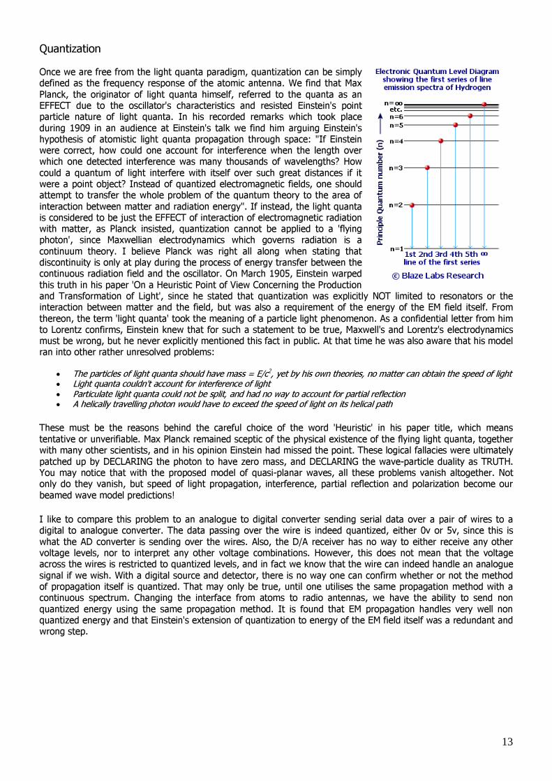
Quantization Once we are free from the light quanta paradigm, quantization can be simply defined as the frequency response of the atomic antenna. We find that Max Planck, the originator of light quanta himself, referred to the quanta as an EFFECT due to the oscillator's characteristics and resisted Einstein's point particle nature of light quanta. In his recorded remarks which took place during 1909 in an audience at Einstein's talk we find him arguing Einstein's hypothesis of atomistic light quanta propagation through space: "If Einstein were correct, how could one account for interference when the length over which one detected interference was many thousands of wavelengths? How could a quantum of light interfere with itself over such great distances if it were a point object? Instead of quantized electromagnetic fields, one should attempt to transfer the whole problem of the quantum theory to the area of interaction between matter and radiation energy". If instead, the light quanta is considered to be just the EFFECT of interaction of electromagnetic radiation with matter, as Planck insisted, quantization cannot be applied to a 'flying photon', since Maxwellian electrodynamics which governs radiation is a continuum theory. I believe Planck was right all along when stating that discontinuity is only at play during the process of energy transfer between the continuous radiation field and the oscillator. On March 1905, Einstein warped this truth in his paper 'On a Heuristic Point of View Concerning the Production and Transformation of Light', since he stated that quantization was explicitly NOT limited to resonators or the interaction between matter and the field, but was also a requirement of the energy of the EM field itself. From thereon, the term 'light quanta' took the meaning of a particle light phenomenon. As a confidential letter from him to Lorentz confirms, Einstein knew that for such a statement to be true, Maxwell's and Lorentz's electrodynamics must be wrong, but he never explicitly mentioned this fact in public. At that time he was also aware that his model ran into other rather unresolved problems:
• The particles of light quanta should have mass = E/c2, yet by his own theories, no matter can obtain the speed of light • Light quanta couldn't account for interference of light • Particulate light quanta could not be split, and had no way to account for partial reflection • A helically travelling photon would have to exceed the speed of light on its helical path
These must be the reasons behind the careful choice of the word 'Heuristic' in his paper title, which means tentative or unverifiable. Max Planck remained sceptic of the physical existence of the flying light quanta, together with many other scientists, and in his opinion Einstein had missed the point. These logical fallacies were ultimately patched up by DECLARING the photon to have zero mass, and DECLARING the wave-particle duality as TRUTH. You may notice that with the proposed model of quasi-planar waves, all these problems vanish altogether. Not only do they vanish, but speed of light propagation, interference, partial reflection and polarization become our beamed wave model predictions! I like to compare this problem to an analogue to digital converter sending serial data over a pair of wires to a digital to analogue converter. The data passing over the wire is indeed quantized, either 0v or 5v, since this is what the AD converter is sending over the wires. Also, the D/A receiver has no way to either receive any other voltage levels, nor to interpret any other voltage combinations. However, this does not mean that the voltage across the wires is restricted to quantized levels, and in fact we know that the wire can indeed handle an analogue signal if we wish. With a digital source and detector, there is no way one can confirm whether or not the method of propagation itself is quantized. That may only be true, until one utilises the same propagation method with a continuous spectrum. Changing the interface from atoms to radio antennas, we have the ability to send non quantized energy using the same propagation method. It is found that EM propagation handles very well non quantized energy and that Einstein's extension of quantization to energy of the EM field itself was a redundant and wrong step.

14
Fig.10 Resonant frequencies (energy levels) expected from a typical fractal antenna
The discontinuities which are experimentally known to occur are simply multiple resonant frequency peaks (Fig.7) set within the antenna structure of each atom. Each atom can be a very efficient transmitter or receiver on a number of different stations, all preset in their memory due to their internal nuclear structure. It is not surprising that unless the transmitter is transmitting on an energy level (frequency) for which the receiver can be tuned, the receiver will never get into resonance even if one increases the intensity/ carrier amplitude of the transmitting source. It is my understanding that every atom must indeed be working in a very similar way to a fractal antenna, in that its frequency response is not peaked on a single frequency, but on a geometric progression of channels governed by its internal nuclear structure. These preset channels are what today we refer to as the quantum levels. Figure 10 shows how easily understandable these energy levels become when one considers them the result of resonances of different pieces of a fractal atomic structure. Wavelengths generated between intermediate structure levels would also explain the existence of the Lyman, Paschen, and Brackett line series. All quantum mechanics can be explained using our present knowledge of electromagnetic fields, eliminating the wrong concepts of probability and duality.