a theoretical formulation for the stress analysis of …...sludge. the stresses and deformations in...
TRANSCRIPT
Engineering Structures 87 (2015) 21–31
Contents lists available at ScienceDirect
Engineering Structures
journal homepage: www.elsevier .com/ locate /engstruct
A theoretical formulation for the stress analysis of multi-segmentedspherical shells for high-volume liquid containment
http://dx.doi.org/10.1016/j.engstruct.2015.01.0020141-0296/� 2015 Elsevier Ltd. All rights reserved.
⇑ Corresponding author. Tel.: +27 (21) 650 2601; fax: +27 (21) 650 3293.E-mail address: [email protected] (A. Zingoni).
Alphose Zingoni ⇑, Batho Mokhothu, Nosakhare EnomaDepartment of Civil Engineering, University of Cape Town, Rondebosch, 7701 Cape Town, South Africa
a r t i c l e i n f o
Article history:Received 1 October 2014Revised 31 December 2014Accepted 2 January 2015
Keywords:Shell of revolutionShell analysisContainment shellDiscontinuity stressesStorage vesselMembrane theory of shellsBending theory of shells
a b s t r a c t
A linear-elastic theoretical formulation is presented for the complete determination of the state of stressin large thin-walled liquid-filled vessels in the form of multi-segmented spherical shells. The transfer ofmembrane forces between adjacent shell segments is such that only vertical equilibrium of stress resul-tants needs to be preserved. The edge effect in the vicinity of the shell junctions is quantified on the basisof an approximate but accurate bending theory for spherical shells. The effectiveness of the developedformulation is demonstrated by consideration of a numerical example. Agreement with the results offinite-element modelling is excellent, showing that the presented theoretical formulation is a reliable,computationally efficient and accurate means of obtaining stresses in large multi-segmented sphericalvessels.
� 2015 Elsevier Ltd. All rights reserved.
1. Introduction
Thin synclastic shells of revolution find widespread applicationin the storage of liquids [1], on account of the structural efficiencyof shells of double curvature, which allows very thin shells to resistrelatively large hydrostatic pressures without rupture. Contain-ment shells of double curvature come in a variety of shapes, fromspherical, ellipsoidal, toroidal and other basic mathematical pro-files, to combinations of these profiles, giving an almost limitlessrange of possibilities. The construction may be in thin metal, orin prestressed concrete. However, where compressive stressesexist, these structures are vulnerable to local buckling on accountof the thin-ness of the shell, particularly in the case of metal con-struction. The thickness of the shell may be enhanced in such zonesto counter any tendencies for local buckling, or stiffeners may beadded to the basic shell.
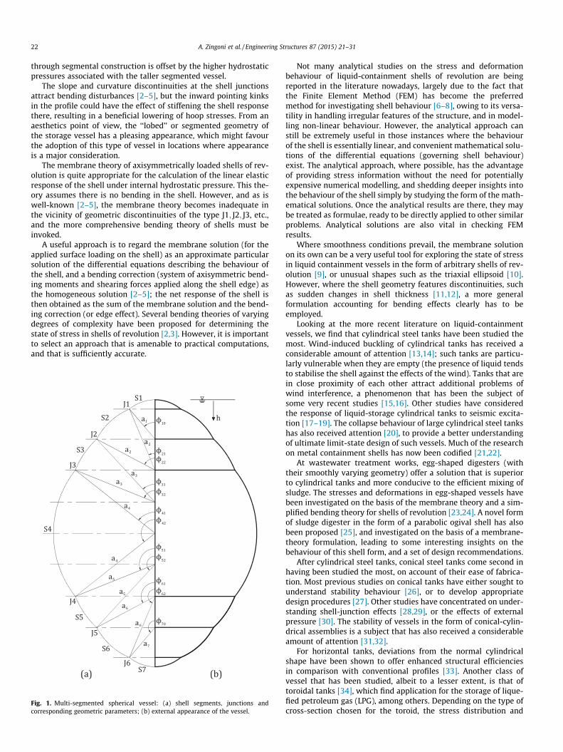
Fig. 1 shows a novel form of construction for high-capacityliquid-storage vessels. The construction consists of an assemblyof spherical shell segments of different radii, whose centres of cur-vatures all lie on the axis of revolution of the vessel taken as awhole. Thus the segments are axisymmetric in shape, where theuppermost segment is actually a cap, and successive lower
segments are typically spherical frusta. Let us denote the variousshells regions or segments, from top to bottom, by S1; S2; S3 andso forth. The junctions between these shell segments are denotedby J1; J2; J3 and so forth. The radii of shell S1; S2; S3, etc. aredenoted by a1; a2; a3 and so forth. As is usual for shells of revolu-tion, the angular coordinate / (which is the angle between the nor-mal to the shell midsurface at any given point, and the axis ofrevolution of the shell assembly) is used to define the positionof any point on the shell. For the shell cap S1 (uppermost portionof the assembly), the angular coordinate of the edge of the cap isdenoted by /10. For all other segments Si (i = 2, 3, 4, etc.) belowthis, the upper and lower edges of segment Si are defined by thecoordinates /i1 and /i2 respectively.
Starting from the central segment (S4 in our illustration), theaddition of segments S3; S2 and S1, with slope enhancements ofð/32 � /41Þ, ð/22 � /31Þ and ð/10 � /21Þ at junctions J3; J2 and J1respectively, adds height and additional storage capacity to thebasic spherical vessel of radius a4. Similar enhancements in capac-ity are also achieved by the addition of segments S5; S6 and S7 inthe lower part of the vessel. The overall result is a spherical assem-bly of relatively large storage capacity. It is interesting to note thatif this was a pressure vessel, to achieve the same storage capacitywhile keeping the vessel of constant radius would require a sphereof radius bigger than a4, which would attract higher shell stresses(these are proportional to the radius), but in the present case ofliquid containment, the stress-reducing benefit of radius limitation
22 A. Zingoni et al. / Engineering Structures 87 (2015) 21–31
through segmental construction is offset by the higher hydrostaticpressures associated with the taller segmented vessel.
The slope and curvature discontinuities at the shell junctionsattract bending disturbances [2–5], but the inward pointing kinksin the profile could have the effect of stiffening the shell responsethere, resulting in a beneficial lowering of hoop stresses. From anaesthetics point of view, the ‘‘lobed’’ or segmented geometry ofthe storage vessel has a pleasing appearance, which might favourthe adoption of this type of vessel in locations where appearanceis a major consideration.
The membrane theory of axisymmetrically loaded shells of rev-olution is quite appropriate for the calculation of the linear elasticresponse of the shell under internal hydrostatic pressure. This the-ory assumes there is no bending in the shell. However, and as iswell-known [2–5], the membrane theory becomes inadequate inthe vicinity of geometric discontinuities of the type J1; J2; J3, etc.,and the more comprehensive bending theory of shells must beinvoked.
A useful approach is to regard the membrane solution (for theapplied surface loading on the shell) as an approximate particularsolution of the differential equations describing the behaviour ofthe shell, and a bending correction (system of axisymmetric bend-ing moments and shearing forces applied along the shell edge) asthe homogeneous solution [2–5]; the net response of the shell isthen obtained as the sum of the membrane solution and the bend-ing correction (or edge effect). Several bending theories of varyingdegrees of complexity have been proposed for determining thestate of stress in shells of revolution [2,3]. However, it is importantto select an approach that is amenable to practical computations,and that is sufficiently accurate.
h
S4
S3
S2
S1
S5
S6
S7
J2
J1
J4
J3
J6
J5
ϕ10
a1
a2
a3
a4
a5
a6
a2
a3
a4
a5
a6
ϕ21
ϕ22
ϕ31
ϕ32
ϕ41
ϕ42
ϕ51
ϕ52
ϕ61
ϕ62
ϕ70
a7
Fig. 1. Multi-segmented spherical vessel: (a) shell segments, junctions andcorresponding geometric parameters; (b) external appearance of the vessel.
Not many analytical studies on the stress and deformationbehaviour of liquid-containment shells of revolution are beingreported in the literature nowadays, largely due to the fact thatthe Finite Element Method (FEM) has become the preferredmethod for investigating shell behaviour [6–8], owing to its versa-tility in handling irregular features of the structure, and in model-ling non-linear behaviour. However, the analytical approach canstill be extremely useful in those instances where the behaviourof the shell is essentially linear, and convenient mathematical solu-tions of the differential equations (governing shell behaviour)exist. The analytical approach, where possible, has the advantageof providing stress information without the need for potentiallyexpensive numerical modelling, and shedding deeper insights intothe behaviour of the shell simply by studying the form of the math-ematical solutions. Once the analytical results are there, they maybe treated as formulae, ready to be directly applied to other similarproblems. Analytical solutions are also vital in checking FEMresults.
Where smoothness conditions prevail, the membrane solutionon its own can be a very useful tool for exploring the state of stressin liquid containment vessels in the form of arbitrary shells of rev-olution [9], or unusual shapes such as the triaxial ellipsoid [10].However, where the shell geometry features discontinuities, suchas sudden changes in shell thickness [11,12], a more generalformulation accounting for bending effects clearly has to beemployed.
Looking at the more recent literature on liquid-containmentvessels, we find that cylindrical steel tanks have been studied themost. Wind-induced buckling of cylindrical tanks has received aconsiderable amount of attention [13,14]; such tanks are particu-larly vulnerable when they are empty (the presence of liquid tendsto stabilise the shell against the effects of the wind). Tanks that arein close proximity of each other attract additional problems ofwind interference, a phenomenon that has been the subject ofsome very recent studies [15,16]. Other studies have consideredthe response of liquid-storage cylindrical tanks to seismic excita-tion [17–19]. The collapse behaviour of large cylindrical steel tankshas also received attention [20], to provide a better understandingof ultimate limit-state design of such vessels. Much of the researchon metal containment shells has now been codified [21,22].
At wastewater treatment works, egg-shaped digesters (withtheir smoothly varying geometry) offer a solution that is superiorto cylindrical tanks and more conducive to the efficient mixing ofsludge. The stresses and deformations in egg-shaped vessels havebeen investigated on the basis of the membrane theory and a sim-plified bending theory for shells of revolution [23,24]. A novel formof sludge digester in the form of a parabolic ogival shell has alsobeen proposed [25], and investigated on the basis of a membrane-theory formulation, leading to some interesting insights on thebehaviour of this shell form, and a set of design recommendations.
After cylindrical steel tanks, conical steel tanks come second inhaving been studied the most, on account of their ease of fabrica-tion. Most previous studies on conical tanks have either sought tounderstand stability behaviour [26], or to develop appropriatedesign procedures [27]. Other studies have concentrated on under-standing shell-junction effects [28,29], or the effects of externalpressure [30]. The stability of vessels in the form of conical-cylin-drical assemblies is a subject that has also received a considerableamount of attention [31,32].
For horizontal tanks, deviations from the normal cylindricalshape have been shown to offer enhanced structural efficienciesin comparison with conventional profiles [33]. Another class ofvessel that has been studied, albeit to a lesser extent, is that oftoroidal tanks [34], which find application for the storage of lique-fied petroleum gas (LPG), among others. Depending on the type ofcross-section chosen for the toroid, the stress distribution and
A. Zingoni et al. / Engineering Structures 87 (2015) 21–31 23
stability behaviour can differ quite markedly from one toroidalform to another. For a general appreciation of the great diversityof shell forms that are available for liquid-storage purposes, thereader is referred to the excellent survey of Tooth [1]. A generalreview of shell buckling has also been conducted by Teng [35].
In this paper, we will focus on large liquid containment shellstructures of the type depicted in Fig. 1, and develop an analyticalformulation for the complete stress determination in such vessels.The considerations only apply to the behaviour of the shell assem-bly within the linear elastic range. This is justified since linear elas-tic response is often used as a basis of preliminary design andcompliance with serviceability requirements, with non-linear sim-ulations being reserved for investigating large displacements,buckling and collapse behaviour of the shell.
It is worth pointing out that the presented general solutionstrategy for liquid containment vessels of the type in question isalso applicable for other multi-segmented shell structures suchas roof domes, the only difference being the loading to which theshells are subjected.
2. Loading preliminaries
Assuming the vessel is completely filled with liquid of weight cper unit volume, the hydrostatic pressure pr on the inside surfaceof the shell at a depth h from the top (refer to Fig. 1) is given by
pr ¼ ch ð1Þ
Let us denote by hið/Þ the depth of liquid at the coordinate / ofshell Si. For the very top shell (S1), which has a radius a1, the depthof liquid at any given point is given by
h1ð/Þ ¼ a1ð1� cos/Þ ½0 6 / 6 /10� ð2aÞ
At / ¼ /10, we have
h10 ¼ a1ð1� cos/10Þ ð2bÞ
For shell S2, which has a radius of a2, the depth of liquid at thecoordinate / of this shell (notice that each shell has its own rangeof / values) is given by
h2ð/Þ ¼ h10 þ a2ðcos/21 � cos/Þ ½/21 6 / 6 /22� ð3aÞ
At / ¼ /22, we have
h22 ¼ h10 þ a2ðcos/21 � cos/22Þ ð3bÞ
For shell S3, which has a radius of a3, the depth of liquid at thecoordinate / of this shell is given by
h3ð/Þ ¼ h22 þ a3ðcos/31 � cos/Þ ½/31 6 / 6 /32� ð4aÞ
At / ¼ /32, we have
h32 ¼ h22 þ a3ðcos/31 � cos/32Þ ð4bÞ
In general, for shell Si (i > 2), which has a radius of ai, the depthof liquid at the coordinate / of this shell is given by
hið/Þ ¼ hði�1Þ2 þ aiðcos/i1 � cos/Þ ½/i1 6 / 6 /i2� ð5aÞ
At / ¼ /i2, we have
hi2 ¼ hði�1Þ2 þ aiðcos/i1 � cos/i2Þ ð5bÞ
A more general way of expressing the results for all shellregions Si, where this time i ¼ 1;2; . . . ; I (I being the total numberof shell segments, e.g. I ¼ 7 for the vessel in Fig. 1), is achievedby writing hið/Þ as follows:
hið/Þ ¼ ki � aicos/ ð6Þ
where the parameter ki is a constant defined differently for the var-ious regions as follows:
for i ¼ 1 : ki ¼ k1 ¼ a1 ð7aÞfor i ¼ 2 : ki ¼ k2 ¼ h10 þ a2cos/21 ð7bÞfor 2 < i < I : ki ¼ hði�1Þ2 þ aicos/i1 ð7cÞfor i ¼ I : ki ¼ kI ¼ hðI�1Þ2 þ aIcos/I0 ð7dÞ
Substituting the above generalised expression for hið/Þ in Eq.(1), the hydrostatic pressure pr at any given point of any given shellSi (i ¼ 1;2; . . . ; I) becomes
prð/Þ ¼ chið/Þ ¼ cki � caicos/ ð8Þ
3. Membrane stress resultants
For axisymmetrically loaded shells of revolution, the meridionaland hoop membrane stress resultants (forces per unit length of theshell, considered positive when tensile) are given by the well-known general solutions [3–5]
N/ ¼1
r2 sin2 /
Zr1r2ðpr cos /� p/ sin /Þ sin /d/þ A ð9Þ
N/
r1þ Nh
r2¼ pr ð10Þ
where r1 and r2 are principal radii of curvature of the shell midsur-face at the point in question, pr and p/ are loading components(forces per unit area of the shell surface) normal to the shell midsur-face and tangential to the shell meridian respectively, and A is aconstant of integration.
For a spherical shell, r1 ¼ r2 ¼ a (radius of the spherical shell). Ifhydrostatic pressure is the only loading applied, then p/ ¼ 0. Eq.(9) simplifies to
N/ ¼1
ai sin2 /a2
i
Zpr cos / sin /d/þ Bi
� �ð11Þ
for every spherical shell region Si of the vessel in Fig. 1. Substitutingthe expression for pr (Eq. (8)) into this equation and evaluating theintegral, we obtain
N/ ¼16
ca2i
sin2 /2 cos3 /� 3
ki
aicos2 /þ Ci
� �ð12Þ
where the constant of integration Ci has to be evaluated from a suit-able boundary condition.
The constant of integration Ci for the end shells (shell S1 andshell SI) may be evaluated from the finiteness condition for N/ inthese regions. For shell S1 (top of the vessel),
Nð1Þ/ ¼16
ca21
sin2 /2 cos3 /� 3 cos2 /þ C1� �
ð13aÞ
(the notation Nð1Þ/ denoting N/ for shell S1). The finiteness conditionfor N/ at / ¼ 0 (apex of the vessel) gives C1 ¼ 1, so that
Nð1Þ/ ¼ca2
1
61� cos /1þ cos /
� �ð1þ 2 cos /Þ ð13bÞ
The hoop stress resultant follows from Eq. (10):
Nð1Þh ¼ca2
1
61� cos /1þ cos /
� �ð5þ 4 cos /Þ ð13cÞ
These are well-known results for spherical tanks [3,5].For shell SI (bottom of the vessel), with the parameter kI as
defined by expression (7d), Eq. (12) may be written as
NðIÞ/ ¼16
ca2I
sin2 /2 cos3 /� 3
kI
aIcos2 /þ CI
� �ð14aÞ
24 A. Zingoni et al. / Engineering Structures 87 (2015) 21–31
The finiteness condition for N/ at / ¼ p (the zenith of the ves-sel) gives
CI ¼ 2þ 3kI
aIð14bÞ
The meridional and hoop stress resultants in this part of thevessel (shell SI) are therefore:
NðIÞ/ ¼16
ca2I
sin2 /2þ 3
kI
aIsin2 /þ 2 cos3 /
� �ð14cÞ
NðIÞh ¼16ca2
I 3kI
aIþ 2
1� cos /
� �ð2 cos2 /� 2 cos /� 1Þ
� ð14dÞ
Consider the interface of shell S1 and shell S2 (that is, junctionJ1 in Fig. 1). For shell S1, the value of N/ at junction J1 (where / forthis shell is equal to /10) is given by:
Nð1Þ/
�/¼/10
¼ Nð1Þ/1 ¼16
ca21
sin2 /10
1� 3 cos2 /10 þ 2 cos3 /10
� �ð15Þ
For shell S2, the value of N/ at junction J1 (where / for this shellis equal to /21) is given by:
Nð2Þ/
�/¼/21
¼Nð2Þ/1 ¼16
ca22
sin2 /21
2cos3 /21�3k2
a2cos2 /21þC2
� �ð16Þ
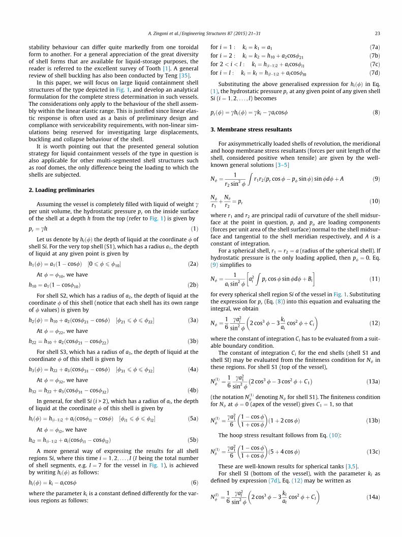
Fig. 2 shows the forces acting upon the portion of the vesselabove a horizontal cross-section Y–Y located at an arbitrary depthy below the apex of the vessel and within the domain of shell S2.We will refer to such a single-edged portion of the vessel as acap. Let the radius of the circular edge of the cap be denoted byR. The force WðyÞ represents the vertical resultant of the hydro-static pressure acting over the entire surface of the cap. Treatingthe cap as a free-body diagram, we see that WðyÞ is balanced bythe vertical component of the stress resultants N/ðyÞ acting alongthe circular edge of the cap. We may therefore write:
WðyÞ ¼ N/ðyÞ sin /ð2pRÞ ð17Þ
Let the vertical resultant on the portion of the vessel abovejunction J1 (that is, on shell S1) be denoted by Wo. Let the valueof R at junction J1 be denoted by R1. At junction J1, just within shellS1, we may write
Wo ¼ Nð1Þ/1 sin/10ð2pR1Þ ð18aÞ
and just within shell S2, we may write
Wo ¼ Nð2Þ/1 sin/21ð2pR1Þ ð18bÞ
From these two expressions for Wo, we deduce that
Nð2Þ/1 ¼sin /10
sin /21
� �Nð1Þ/1 ð19aÞ
Fig. 2. Forces acting upon a spherical cap above a horizontal section Y–Y.
which is the condition of vertical equilibrium at junction J1. Substi-tuting the expressions for Nð1Þ/1 and Nð2Þ/1 (Eqs. (15) and (16)) into Eq.(19a), we obtain
16
ca22
sin2 /21
2 cos3 /21 � 3k2
a2cos2 /21 þ C2
� �
¼ sin /10
sin /21
� �16
ca21
sin2 /10
1� 3 cos2 /10 þ 2 cos3 /10
� �ð19bÞ
giving the solution
C2 ¼a2
1
a22
sin/21
sin/10
� �1�3cos2 /10þ2cos3 /10
� ��2cos3 /21þ3
k2
a2cos2 /21 ð20Þ
Using this result in Eq. (12) (to eliminate Ci for i ¼ 2), we canwrite N/ for shell S2 in explicit form, and in turn using the ensuingexpression for N/ in Eq. (10), we also obtain the hoop stress resul-tant Nh in explicit form. The results are:
Nð2Þ/ ¼16
ca22
sin2 /2cos3 /�3
k2
a2cos2 /
� �� 2cos3 /21�3
k2
a2cos2 /21
� ��
þa21
a22
sin/21
sin/10
� �1�3cos2 /10þ2cos3 /10
� �ð21aÞ
Nð2Þh ¼ a2pr � Nð2Þ/ ¼ca2
2
66
k2
a2� cos /
� �� 1
sin2 /
"
2 cos3 /� 3k2
a2cos2 /
� �� 2 cos3 /21 � 3
k2
a2cos2 /21
� ��
þ a21
a22
sin /21
sin /10
� �1� 3 cos2 /10 þ 2 cos3 /10
� ��ð21bÞ
where from Eqs. (7b) and (2b), k2 has the explicit form
k2 ¼ h10 þ a2 cos /21 ¼ a1ð1� cos /10Þ þ a2 cos /21 ð22Þ
For any subsequent shell Si (i > 2), the Ci in Eq. (12) is obtainedfrom
NðiÞ/ði�1Þ ¼sin /ði�1Þ2
sin /i1
� �Nði�1Þ
/ði�1Þ ð23Þ
which is the condition of vertical equilibrium at junction Jði� 1Þ,noting that the ði� 1Þ in the subscript for N/ refers to junctionJði� 1Þ between shell Sði� 1Þ and shell Si. Expanding the N/ termsin Eq. (23) on the basis of Eq. (12), and re-arranging, we obtain
Ci¼a2
i�1
a2i
sin/i1
sin/ði�1Þ2
!2cos3 /ði�1Þ2�3
ki�1
ai�1cos2 /ði�1Þ2þCi�1
� �
� 2cos3 /i1�3ki
aicos2 /i1
� �ð24Þ
where Ci�1 is known from the preceding step. With Ci nowknown, the stress resultants NðiÞ/ and NðiÞh for shell Si (wherei ¼ 3;4; . . . ; ðI � 1ÞÞ then follow:
NðiÞ/ ¼16
ca2i
sin2 /2cos3 /�3
ki
aicos2 /
� �� 2cos3 /i1�3
ki
aicos2 /i1
� ��
þa2i�1
a2i
sin/i1
sin/ði�1Þ2
!2cos3 /ði�1Þ2�3
ki�1
ai�1cos2 /ði�1Þ2þCi�1
� �)ð25aÞ
NðiÞh ¼ca2
i
66
ki
ai� cos /
� �� 1
sin2 /2 cos3 /� 3
ki
aicos2 /
� ��"
� 2 cos3 /i1 � 3ki
aicos2 /i1
� �þ a2
i�1
a2i
sin /i1
sin /ði�1Þ2
!�
2 cos3 /ði�1Þ2�3ki�1
ai�1cos2 /ði�1Þ2 þ Ci�1
�#ð25bÞ
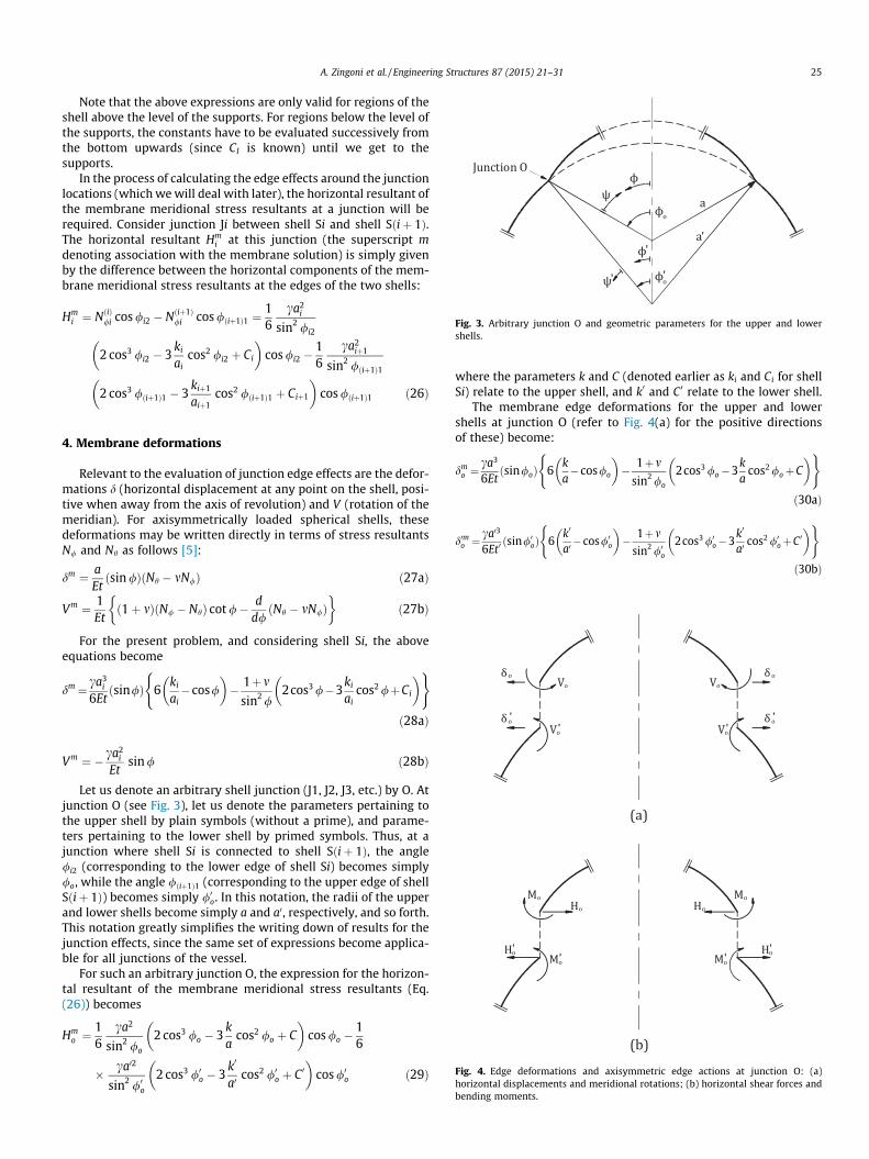
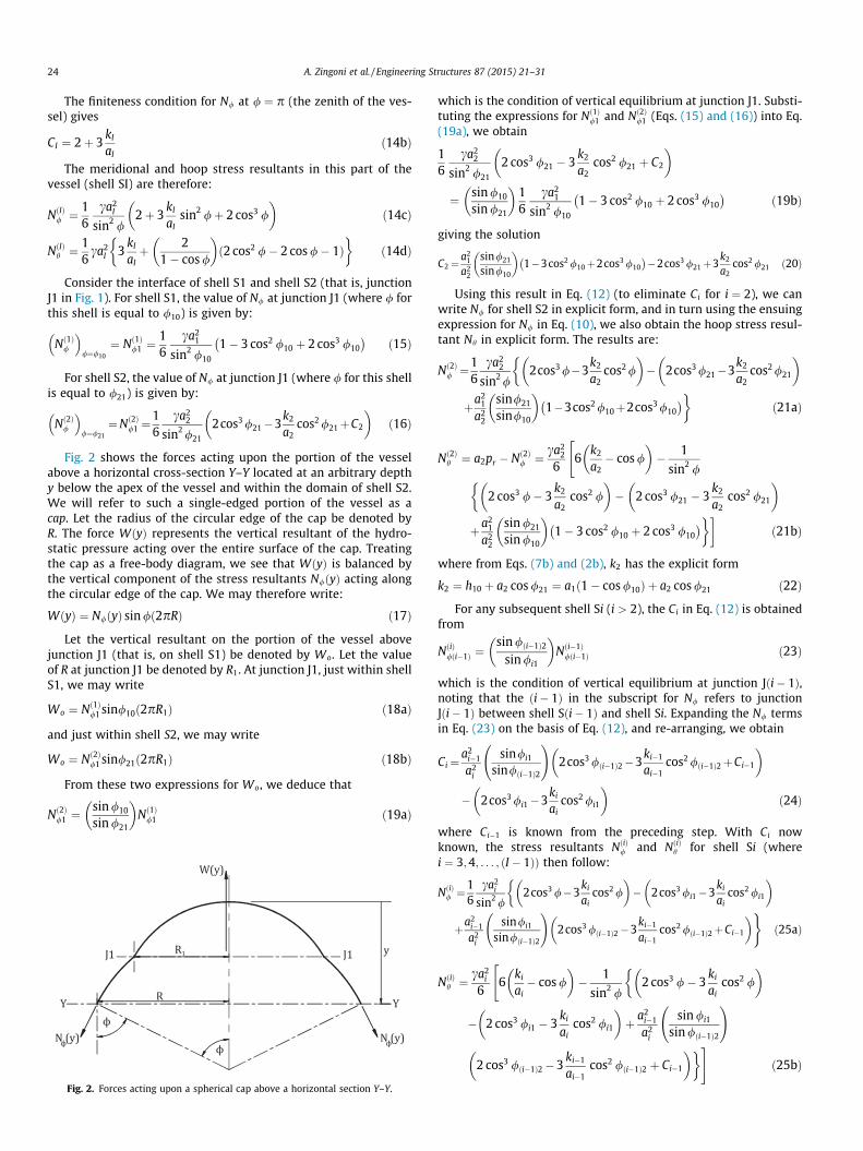
Fig. 3. Arbitrary junction O and geometric parameters for the upper and lowershells.
A. Zingoni et al. / Engineering Structures 87 (2015) 21–31 25
Note that the above expressions are only valid for regions of theshell above the level of the supports. For regions below the level ofthe supports, the constants have to be evaluated successively fromthe bottom upwards (since CI is known) until we get to thesupports.
In the process of calculating the edge effects around the junctionlocations (which we will deal with later), the horizontal resultant ofthe membrane meridional stress resultants at a junction will berequired. Consider junction Ji between shell Si and shell Sðiþ 1Þ.The horizontal resultant Hm
i at this junction (the superscript mdenoting association with the membrane solution) is simply givenby the difference between the horizontal components of the mem-brane meridional stress resultants at the edges of the two shells:
Hmi ¼ NðiÞ/i cos /i2 � Nðiþ1Þ
/i cos /ðiþ1Þ1 ¼16
ca2i
sin2 /i2
2 cos3 /i2 � 3ki
aicos2 /i2 þ Ci
� �cos /i2 �
16
ca2iþ1
sin2 /ðiþ1Þ1
2 cos3 /ðiþ1Þ1 � 3kiþ1
aiþ1cos2 /ðiþ1Þ1 þ Ciþ1
� �cos /ðiþ1Þ1 ð26Þ
Fig. 4. Edge deformations and axisymmetric edge actions at junction O: (a)horizontal displacements and meridional rotations; (b) horizontal shear forces and
4. Membrane deformations
Relevant to the evaluation of junction edge effects are the defor-mations d (horizontal displacement at any point on the shell, posi-tive when away from the axis of revolution) and V (rotation of themeridian). For axisymmetrically loaded spherical shells, thesedeformations may be written directly in terms of stress resultantsN/ and Nh as follows [5]:
dm ¼ aEtðsin /ÞðNh � mN/Þ ð27aÞ
Vm ¼ 1Etð1þ mÞðN/ � NhÞ cot /� d
d/ðNh � mN/Þ
� ð27bÞ
For the present problem, and considering shell Si, the aboveequations become
dm¼ ca3i
6Etðsin/Þ 6
ki
ai�cos/
� �� 1þm
sin2 /2cos3 /�3
ki
aicos2 /þCi
� �( )
ð28aÞ
Vm ¼ � ca2i
Etsin / ð28bÞ
Let us denote an arbitrary shell junction (J1, J2, J3, etc.) by O. Atjunction O (see Fig. 3), let us denote the parameters pertaining tothe upper shell by plain symbols (without a prime), and parame-ters pertaining to the lower shell by primed symbols. Thus, at ajunction where shell Si is connected to shell Sðiþ 1Þ, the angle/i2 (corresponding to the lower edge of shell Si) becomes simply/o, while the angle /ðiþ1Þ1 (corresponding to the upper edge of shellSðiþ 1Þ) becomes simply /0o. In this notation, the radii of the upperand lower shells become simply a and a0, respectively, and so forth.This notation greatly simplifies the writing down of results for thejunction effects, since the same set of expressions become applica-ble for all junctions of the vessel.
For such an arbitrary junction O, the expression for the horizon-tal resultant of the membrane meridional stress resultants (Eq.(26)) becomes
Hmo ¼
16
ca2
sin2 /o
2 cos3 /o � 3ka
cos2 /o þ C� �
cos /o �16
� ca02
sin2 /0o2 cos3 /0o � 3
k0
a0cos2 /0o þ C 0
� �cos /0o ð29Þ
where the parameters k and C (denoted earlier as ki and Ci for shellSi) relate to the upper shell, and k0 and C0 relate to the lower shell.
The membrane edge deformations for the upper and lowershells at junction O (refer to Fig. 4(a) for the positive directionsof these) become:
dmo ¼
ca3
6Etðsin/oÞ 6
ka�cos/o
� �� 1þm
sin2 /o
2cos3 /o�3ka
cos2 /oþC� �( )
ð30aÞ
d0mo ¼ca03
6Et0ðsin/0oÞ 6
k0
a0�cos/0o
� �� 1þm
sin2 /0o2cos3 /0o�3
k0
a0cos2 /0oþC0
� �( )
ð30bÞ
bending moments.

26 A. Zingoni et al. / Engineering Structures 87 (2015) 21–31
Vmo ¼ �
ca2
Etsin /o ð31aÞ
V 0mo ¼ �ca02
Et0sin /0o ð31bÞ
where the thickness parameters t and t0 refer to the upper andlower shells respectively.
5. Bending solution
Fig. 4(b) shows a system of axisymmetric bending moments andhorizontal shearing forces applied at the edges of the upper andlower shells at junction O. Each shell will experience interior bend-ing moments, stress resultants and deformations in the vicinity ofthe edge (the so-called ‘‘edge effect’’), in response to the applicationof these axisymmetric edge actions. To quantify the edge effects, wewill adopt the asymptotic solution of Hetényi for the axisymmetricbending of spherical shells [36], which is very accurate providedthat the meridional angle of the shell is not too close to zero or180� (that is, provided / lies in the range 20� 6 / 6 160�).
Based on the spherical-shell bending theory of Hetenyi [36],general expressions for interior stress resultants, bendingmoments and deformations in a spherical shell, due to axisymmet-ric bending moments and shear forces applied at the edge of theshell, have been developed in reference [5]. We may readily applythe results to the problem depicted in Fig. 4(b).
If the meridional angle measured from the shell edge is denotedby w for the upper shell and by w0 for the lower shell, it is clear, byreference to Fig. 3, that w ¼ /o � / for the upper shell, andw0 ¼ /0 � /0o for the lower shell. Let k and k0 denote the shell slen-derness parameters; for the upper shell, k ¼ ½3ð1� m2Þða2=t2Þ�1=4
,and for the lower shell, k0 ¼ ½3ð1� m2Þða02=t02Þ�1=4
.The results for actions in the interior of the shell and deforma-
tions at the shell edge are as follows (the superscript b denotes thatthese quantities are associated with the bending disturbance).
5.1. Upper shell
Nb/ ¼ � cotð/o � wÞ e�kwffiffiffiffiffiffiffiffiffiffiffiffiffiffiffiffiffiffiffiffiffiffiffiffiffi
sinð/o � wÞp 2k
aK1ðsin /oÞ
1=2Mo sin kw
�
�ð1þ K21Þ
1=2
K1ðsin /oÞ
3=2Ho sinðkwþ bÞ)
ð32aÞ
Nbh ¼
k2
e�kwffiffiffiffiffiffiffiffiffiffiffiffiffiffiffiffiffiffiffiffiffiffiffiffisinð/o�wÞ
p 2kaK1ðsin/oÞ
1=2Mof2coskw�ðk1þk2Þsinkwg�
�ð1þK21Þ
1=2
K1ðsin/oÞ
3=2Hof2cosðkwþbÞ� ðk1þk2ÞsinðkwþbÞg#
ð32bÞ
M/¼a
2ke�kwffiffiffiffiffiffiffiffiffiffiffiffiffiffiffiffiffiffiffiffiffiffiffiffi
sinð/o�wÞp 2k
aK1ðsin/oÞ
1=2Mofk1 coskwþsinkwg�
�ð1þK21Þ
1=2
K1ðsin/oÞ
3=2Hofk1 cosðkwþbÞþsinðkwþbÞg#ð33aÞ
Mh ¼a
4kme�kwffiffiffiffiffiffiffiffiffiffiffiffiffiffiffiffiffiffiffiffiffiffiffiffiffi
sinð/o � wÞp 2k
aK1ðsin /oÞ
1=2Mo
�
�½fð1þ m2Þðk1 þ k2Þ � 2k2g cos kwþ 2m2 sin kw�
� ð1þ K21Þ
1=2
K1ðsin /oÞ
3=2Ho � ½fð1þ m2Þðk1 þ k2Þ � 2k2g
� cosðkwþ bÞ þ 2m2 sinðkwþ bÞ��
ð33bÞ
dbo ¼
2k2
EtK1ðsin /oÞMo �
kaEt
1þ K1K2
K1
� �ðsin2 /oÞHo ð34aÞ
Vbo ¼ �
4k3
EatK1Mo þ
2k2
EtK1ðsin /oÞHo ð34bÞ
where
k1 ¼ 1� 1� 2m2k
� �cotð/o � wÞ ð35aÞ
k2 ¼ 1� 1þ 2m2k
� �cotð/o � wÞ ð35bÞ
K1 ¼ 1� 1� 2m2k
� �cot /o ð36aÞ
K2 ¼ 1� 1þ 2m2k
� �cot /o ð36bÞ
b ¼ � tan�1ðK1Þ ð37Þ
5.2. Lower shell
N0b/ ¼ � cotð/0o þ w0Þ e�k0w0ffiffiffiffiffiffiffiffiffiffiffiffiffiffiffiffiffiffiffiffiffiffiffiffiffiffisinð/0o þ w0Þ
p 2k0
a0K 01ðsin /0oÞ
1=2M0o sin k0w0
�
þð1þ K 021 Þ1=2
K 01ðsin /0oÞ
3=2H0o sinðk0w0 þ b0Þ)
ð38aÞ
N0bh ¼k0
2e�k0w0ffiffiffiffiffiffiffiffiffiffiffiffiffiffiffiffiffiffiffiffiffiffiffiffiffi
sinð/0oþw0Þp 2k0
a0K 01ðsin/0oÞ
1=2M0of2cosk0w0 � ðk01þk02Þsink0w0g
�
þð1þK 021 Þ1=2
K 01ðsin/0oÞ
3=2H0of2cosðk0w0 þb0Þ�ðk01þk02Þsinðk0w0 þb0Þg#
ð38bÞ
M0/¼
a0
2k0e�k0w0ffiffiffiffiffiffiffiffiffiffiffiffiffiffiffiffiffiffiffiffiffiffiffiffiffi
sinð/0oþw0Þp 2k0
a0K 01ðsin/0oÞ
1=2M0ofk
01 cosk0w0 þsink0w0g
�
þð1þK 021 Þ1=2
K 01ðsin/0oÞ
3=2H0ofk01 cosðk0w0 þb0Þþ sinðk0w0 þb0Þg
#ð39aÞ
M0h ¼
a0
4k0me�k0w0ffiffiffiffiffiffiffiffiffiffiffiffiffiffiffiffiffiffiffiffiffiffiffiffiffiffi
sinð/0o þ w0Þp 2k0
a0K 01ðsin /0oÞ
1=2M0o � ½fð1þ m2Þðk01 þ k02Þ
�
�2k02g cos k0w0 þ 2m2 sin k0w0� þ ð1þ K 021 Þ1=2
K 01ðsin /0oÞ
3=2H0o
�½fð1þ m2Þðk01 þ k02Þ � 2k02g cosðk0w0 þ b0Þ þ 2m2 sinðk0w0 þ b0Þ��
ð39bÞ
d0bo ¼2k02
Et0K 01ðsin /0oÞM
0o þ
k0a0
Et01þ K 01K 02
K 01
� �ðsin2 /0oÞH
0o ð40aÞ
V 0bo ¼4k03
Ea0t0K 01M0
o þ2k02
Et0K 01ðsin /0oÞH
0o ð40bÞ
where
k01 ¼ 1þ 1� 2m2k0
� �cotð/0o þ w0Þ ð41aÞ
k02 ¼ 1þ 1þ 2m2k0
� �cotð/0o þ w0Þ ð41bÞ
A. Zingoni et al. / Engineering Structures 87 (2015) 21–31 27
K 01 ¼ 1þ 1� 2m2k0
� �cot /0o ð42aÞ
K 02 ¼ 1þ 1þ 2m2k0
� �cot /0o ð42bÞ
b0 ¼ � tan�1ðK 01Þ ð43Þ
6. Evaluation of edge actions
To evaluate the edge actions Mo;Ho;M0o;H
0o, we apply the
boundary conditions of continuity of net deformations across thejunction of the two shells
dTo ¼ d0To ð44aÞ
VTo ¼ V 0To ð44bÞ
and the boundary conditions expressing the equilibrium of an ele-ment at the interface of the two shells, namely that the net torqueand the net horizontal thrust upon such an element must be zero:
Mo �M0o ¼ 0 ð45aÞ
Hmo þ H0o � Ho ¼ 0 ð45bÞ
Net deformations dTo ; d
0To ;V
To ;V
0To are, of course, given by
superimposing the components due to the bending correction –expressions (34) and (40) – with their membrane-solution counter-parts. The latter have already been obtained explicitly (results (30)and (31)), and may therefore be taken as known quantities. Thus
dTo ¼ dm
o þ2k2
EtK1ðsin /oÞMo �
kaEt
1þ K1K2
K1
� �ðsin2 /oÞHo ð46aÞ
d0To ¼ d0mo þ2k02
Et0K 01sin /0o� �
M0o þ
k0a0
Et01þ K 01K 02
K 01
� �sin2 /0o
�H0o ð46bÞ
VTo ¼ Vm
o �4k3
EatK1Mo þ
2k2
EtK1ðsin /oÞHo ð47aÞ
V 0To ¼ V 0mo þ4k03
Ea0t0K 01M0
o þ2k02
Et0K 01ðsin /0oÞH
0o ð47bÞ
From Eq. (45), we obtain the relations
M0o ¼ Mo ð48aÞ
H0o ¼ Ho � Hmo ð48bÞ
where Hmo is a known quantity (result (29)). Using relations (46) and
(47) to write out Eqs. (44) in expanded form, and eliminating M0o
and H0o from the ensuing pair of equations (using relations (48)),we obtain a pair of simultaneous equations in two unknowns Mo
and Ho, which upon solving yield
Mo ¼f 1g1 � f 2g2
f 21 � f 2f 3
ð49aÞ
Ho ¼f 1g2 � f 3g1
f 21 � f 2f 3
ð49bÞ
where
f 1 ¼2E
k2
tK1ðsin /oÞ �
k02
t0K 01ðsin /0oÞ
( )ð50aÞ
f 2 ¼ �1E
kat
1þ K1K2
K1
� �ðsin2 /oÞ þ
k0a0
t01þ K 01K 02
K 01
� �ðsin2 /0oÞ
� ð50bÞ
f 3 ¼ �4E
k3
atK1þ k03
a0t0K 01
!ð50cÞ
g1 ¼ ðd0oÞm � ðdoÞm �
k0a0
Et01þ K 01K 02
K 01
� �sin2 /0o
�Hm
o ð50dÞ
g2 ¼ ðV 0oÞm � ðVoÞm �
2k02
Et0K 01sin /0o� �
Hmo ð50eÞ
The other two edge actions M0o and H0o then follow from rela-
tions (48).
7. Net stresses
With the shell-edge actions fMo;Ho;M0o;H
0og now known, we
can evaluate, from expressions (32), (33), (38) and (39), the bend-ing-related stress resultants fNb
/;Nbh ;N
0b/ ;N
0bh g and bending
moments fM/;Mh;M0/;M
0hg in the two shells. The net stresses on
the inner and outer surfaces of the two shells then follow by super-imposing the membrane-solution stresses with those stemmingfrom the bending correction:
rT/ ¼
Nm/
tþ
Nb/
t� 6M/
t2 ð51aÞ
rTh ¼
Nmh
tþ Nb
h
t� 6Mh
t2 ð51bÞ
r0T/ ¼N0m/t0þ
N0b/t0�
6M0/
t02ð52aÞ
r0Th ¼N0mht0þ N0bh
t0� 6M0
h
t02ð52bÞ
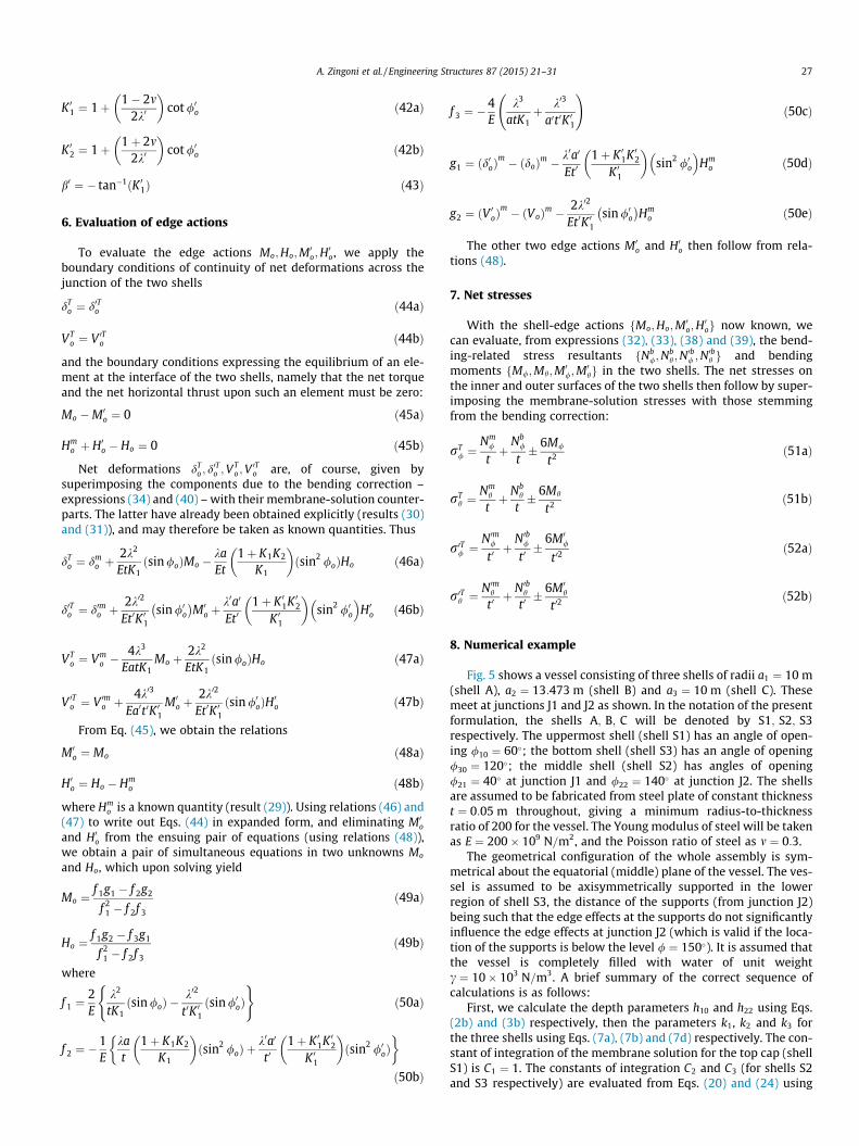
8. Numerical example
Fig. 5 shows a vessel consisting of three shells of radii a1 ¼ 10 m(shell A), a2 ¼ 13:473 m (shell B) and a3 ¼ 10 m (shell C). Thesemeet at junctions J1 and J2 as shown. In the notation of the presentformulation, the shells A; B; C will be denoted by S1; S2; S3respectively. The uppermost shell (shell S1) has an angle of open-ing /10 ¼ 60�; the bottom shell (shell S3) has an angle of opening/30 ¼ 120�; the middle shell (shell S2) has angles of opening/21 ¼ 40� at junction J1 and /22 ¼ 140� at junction J2. The shellsare assumed to be fabricated from steel plate of constant thicknesst ¼ 0:05 m throughout, giving a minimum radius-to-thicknessratio of 200 for the vessel. The Young modulus of steel will be takenas E ¼ 200� 109 N=m2, and the Poisson ratio of steel as m ¼ 0:3.
The geometrical configuration of the whole assembly is sym-metrical about the equatorial (middle) plane of the vessel. The ves-sel is assumed to be axisymmetrically supported in the lowerregion of shell S3, the distance of the supports (from junction J2)being such that the edge effects at the supports do not significantlyinfluence the edge effects at junction J2 (which is valid if the loca-tion of the supports is below the level / ¼ 150�). It is assumed thatthe vessel is completely filled with water of unit weightc ¼ 10� 103 N=m3. A brief summary of the correct sequence ofcalculations is as follows:
First, we calculate the depth parameters h10 and h22 using Eqs.(2b) and (3b) respectively, then the parameters k1, k2 and k3 forthe three shells using Eqs. (7a), (7b) and (7d) respectively. The con-stant of integration of the membrane solution for the top cap (shellS1) is C1 ¼ 1. The constants of integration C2 and C3 (for shells S2and S3 respectively) are evaluated from Eqs. (20) and (24) using
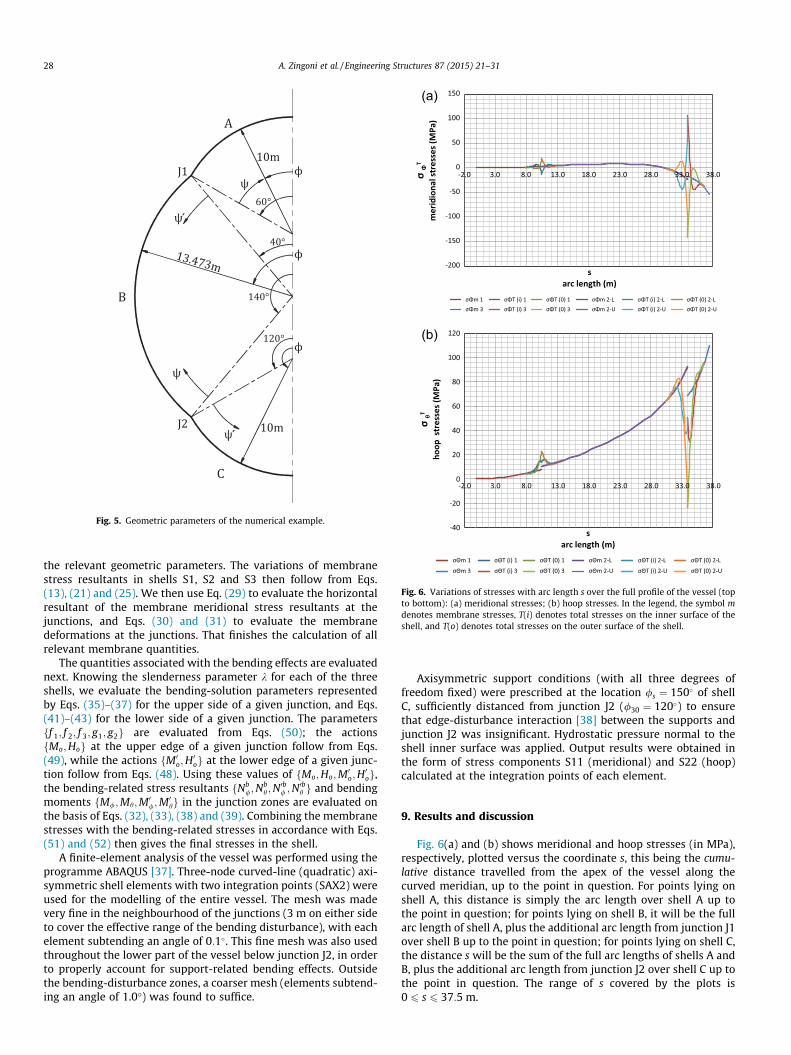
Fig. 5. Geometric parameters of the numerical example.
-200
-150
-100
-50
0
50
100
150
-2.0 3.0 8.0 13.0 18.0 23.0 28.0 33.0 38.0σΦ
T
mer
idio
nal s
tres
ses (
MPa
)
sarc length (m)
σΦm 1 σΦT (i) 1 σΦT (0) 1 σΦm 2-L σΦT (i) 2-L σΦT (0) 2-LσΦm 3 σΦT (i) 3 σΦT (0) 3 σΦm 2-U σΦT (i) 2-U σΦT (0) 2-U
-2.0 3.0 8.0 13.0 18.0 23.0 28.0 33.0 38.0
σθT
hoop
str
esse
s (M
Pa)
sarc length (m)
σΘm 1 σΘT (i) 1 σΘT (0) 1 σΘm 2-L σΘT (i) 2-L σΘT (0) 2-L
σΘm 3 σΘT (i) 3 σΘT (0) 3 σΘm 2-U σΘT (i) 2-U σΘT (0) 2-U
(a)
(b)
Fig. 6. Variations of stresses with arc length s over the full profile of the vessel (topto bottom): (a) meridional stresses; (b) hoop stresses. In the legend, the symbol mdenotes membrane stresses, T(i) denotes total stresses on the inner surface of theshell, and T(o) denotes total stresses on the outer surface of the shell.
28 A. Zingoni et al. / Engineering Structures 87 (2015) 21–31
the relevant geometric parameters. The variations of membranestress resultants in shells S1, S2 and S3 then follow from Eqs.(13), (21) and (25). We then use Eq. (29) to evaluate the horizontalresultant of the membrane meridional stress resultants at thejunctions, and Eqs. (30) and (31) to evaluate the membranedeformations at the junctions. That finishes the calculation of allrelevant membrane quantities.
The quantities associated with the bending effects are evaluatednext. Knowing the slenderness parameter k for each of the threeshells, we evaluate the bending-solution parameters representedby Eqs. (35)–(37) for the upper side of a given junction, and Eqs.(41)–(43) for the lower side of a given junction. The parametersff 1; f 2; f 3; g1; g2g are evaluated from Eqs. (50); the actionsfMo;Hog at the upper edge of a given junction follow from Eqs.(49), while the actions fM0
o;H0og at the lower edge of a given junc-
tion follow from Eqs. (48). Using these values of fMo;Ho;M0o;H
0og,
the bending-related stress resultants fNb/;N
bh ;N
0b/ ;N
0bh g and bending
moments fM/;Mh;M0/;M
0hg in the junction zones are evaluated on
the basis of Eqs. (32), (33), (38) and (39). Combining the membranestresses with the bending-related stresses in accordance with Eqs.(51) and (52) then gives the final stresses in the shell.
A finite-element analysis of the vessel was performed using theprogramme ABAQUS [37]. Three-node curved-line (quadratic) axi-symmetric shell elements with two integration points (SAX2) wereused for the modelling of the entire vessel. The mesh was madevery fine in the neighbourhood of the junctions (3 m on either sideto cover the effective range of the bending disturbance), with eachelement subtending an angle of 0:1�. This fine mesh was also usedthroughout the lower part of the vessel below junction J2, in orderto properly account for support-related bending effects. Outsidethe bending-disturbance zones, a coarser mesh (elements subtend-ing an angle of 1.0�) was found to suffice.
Axisymmetric support conditions (with all three degrees offreedom fixed) were prescribed at the location /s ¼ 150� of shellC, sufficiently distanced from junction J2 (/30 ¼ 120�) to ensurethat edge-disturbance interaction [38] between the supports andjunction J2 was insignificant. Hydrostatic pressure normal to theshell inner surface was applied. Output results were obtained inthe form of stress components S11 (meridional) and S22 (hoop)calculated at the integration points of each element.
9. Results and discussion
Fig. 6(a) and (b) shows meridional and hoop stresses (in MPa),respectively, plotted versus the coordinate s, this being the cumu-lative distance travelled from the apex of the vessel along thecurved meridian, up to the point in question. For points lying onshell A, this distance is simply the arc length over shell A up tothe point in question; for points lying on shell B, it will be the fullarc length of shell A, plus the additional arc length from junction J1over shell B up to the point in question; for points lying on shell C,the distance s will be the sum of the full arc lengths of shells A andB, plus the additional arc length from junction J2 over shell C up tothe point in question. The range of s covered by the plots is0 6 s 6 37:5 m.
-15
-10
-5
0
5
10
15
20
0.0 2.0 4.0 6.0 8.0 10.0 12.0 14.0 16.0 18.0
σΦ
T
mer
idio
nal s
tres
ses (
MPa
)
s arc length (m)
σΦm 1 σΦT (i) 1 σΦT (0) 1 σΦm 2-L σΦT (i) 2-L σΦT (0) 2-LσΦm 3 σΦT (i) 3 σΦT (0) 3 σΦm 2-U σΦT (i) 2-U σΦT (0) 2-U
-150
-100
-50
0
50
100
29.0 30.0 31.0 32.0 33.0 34.0 35.0 36.0 37.0 38.0
σΦ
T
mer
idio
nal s
tres
ses (
MPa
)
sarc length (m)
σΦm 1 σΦT (i) 1 σΦT (0) 1 σΦm 2-L σΦT (i) 2-L σΦT (0) 2-LσΦm 3 σΦT (i) 3 σΦT (0) 3 σΦm 2-U σΦT (i) 2-U σΦT (0) 2-U
(a)
(b)
Fig. 7. Meridional stress variations in the vicinity of the shell junctions: (a) junctionJ1; (b) junction J2. In the legend, the symbol m denotes membrane stresses, T(i)denotes total stresses on the inner surface of the shell, and T(o) denotes totalstresses on the outer surface of the shell.
0
5
10
15
20
25
4.0 6.0 8.0 10.0 12.0 14.0
σθT
hoop
str
esse
s (M
Pa)
s arc length (m)
σΘm 1 σΘT (i) 1 σΘT (0) 1 σΘm 2-L σΘT (i) 2-L σΘT (0) 2-L
σΘm 3 σΘT (i) 3 σΘT (0) 3 σΘm 2-U σΘT (i) 2-U σΘT (0) 2-U
-25
-5
15
35
55
75
95
115
28.0 29.0 30.0 31.0 32.0 33.0 34.0 35.0 36.0 37.0 38.0
σθT
hoop
str
esse
s (M
Pa)
s arc length (m)
σΘm 1 σΘT (i) 1 σΘT (0) 1 σΘm 2-L σΘT (i) 2-L σΘT (0) 2-LσΘm 3 σΘT (i) 3 σΘT (0) 3 σΘm 2-U σΘT (i) 2-U σΘT (0) 2-U
(a)
(b)
Fig. 8. Hoop stress variations in the vicinity of the shell junctions: (a) junction J1;(b) junction J2. In the legend, the symbol m denotes membrane stresses, T(i)denotes total stresses on the inner surface of the shell, and T(o) denotes totalstresses on the outer surface of the shell.
Table 1Meridional stress values (in MPa) at the junction locations.
Junction J1 Junction J2
rm/ rT
/ ðouterÞ rT/ ðinnerÞ rm
/ rT/ ðouterÞ rT
/ ðinnerÞ
Upper side 2.2 18.0 �13.0 �23.3 �141.0 102.4Lower side 3.0 19.0 �12.1 �17.3 �137.1 106.3
Table 2Hoop stress values (in MPa) at the junction locations.
Junction J1 Junction J2
rmh rT
h ðouterÞ rTh ðinnerÞ rm
h rTh ðouterÞ rT
h ðinnerÞ
Upper side 7.8 22.6 13.4 92.4 �23.4 50.5Lower side 10.5 22.6 13.4 68.6 �23.3 50.3
A. Zingoni et al. / Engineering Structures 87 (2015) 21–31 29
In these plots, the gradually varying curves are the membranestresses frm
/ ;rmh g, while the sharply oscillating curves in the vicin-
ity of the junction locations represent total stresses on the innerand outer shell surfaces, that is frT
/ðiÞ;rT/ðoÞg for the meridional-
stress variations in Fig. 6(a), and frTh ðiÞ;rT
h ðoÞg for the hoop-stressvariations in Fig. 6(b). Some observations are as follows:
(i) As expected, the membrane-stress variations show disconti-nuities (or jumps) at both junctions J1 and J2. On combiningthe membrane stresses with the stresses due to the edgeeffect, the total-stress variations show continuity in values(but not of slope) across the junctions.
(ii) The bending-disturbance stresses at the lower junction areseveral times larger than those at the upper junction; thisis because the larger hydrostatic pressures in the lower partof the vessel cause bigger membrane-deformation incom-patibilities, in turn inducing larger bending effects.
(iii) The bending-disturbance stresses are very localised to theshell junctions, dying out within a distance of only 2.5 mon either side of the junctions. However, within these nar-row zones, they sharply rise to magnitudes that are severaltimes larger than the calculated membrane stresses.
(iv) At both the upper and the lower junctions, the bending-disturbance effects result in net meridional stresses in bothtension and compression that are relatively large incomparison with the surrounding membrane stresses.
(v) On the other hand, while the bending disturbance increasesthe relatively modest membrane hoop tension at the upperjunction, it has the beneficial effect of sharply lowering the
-15
-10
-5
0
5
10
15
20
5 7 9 11 13 15 17S (m)
Upper Junc�on
Meridional Stress (MPa) Outer Surface
Meridional Stress (MPa) Inner Surface
-140
-100
-60
-20
20
60
100
29 31 33 35 37 S (m)
Lower Junc�on
Meridional Stress (MPa) Outer Surface
Meridional Stress (MPa) Inner Surface
(a)
(b)
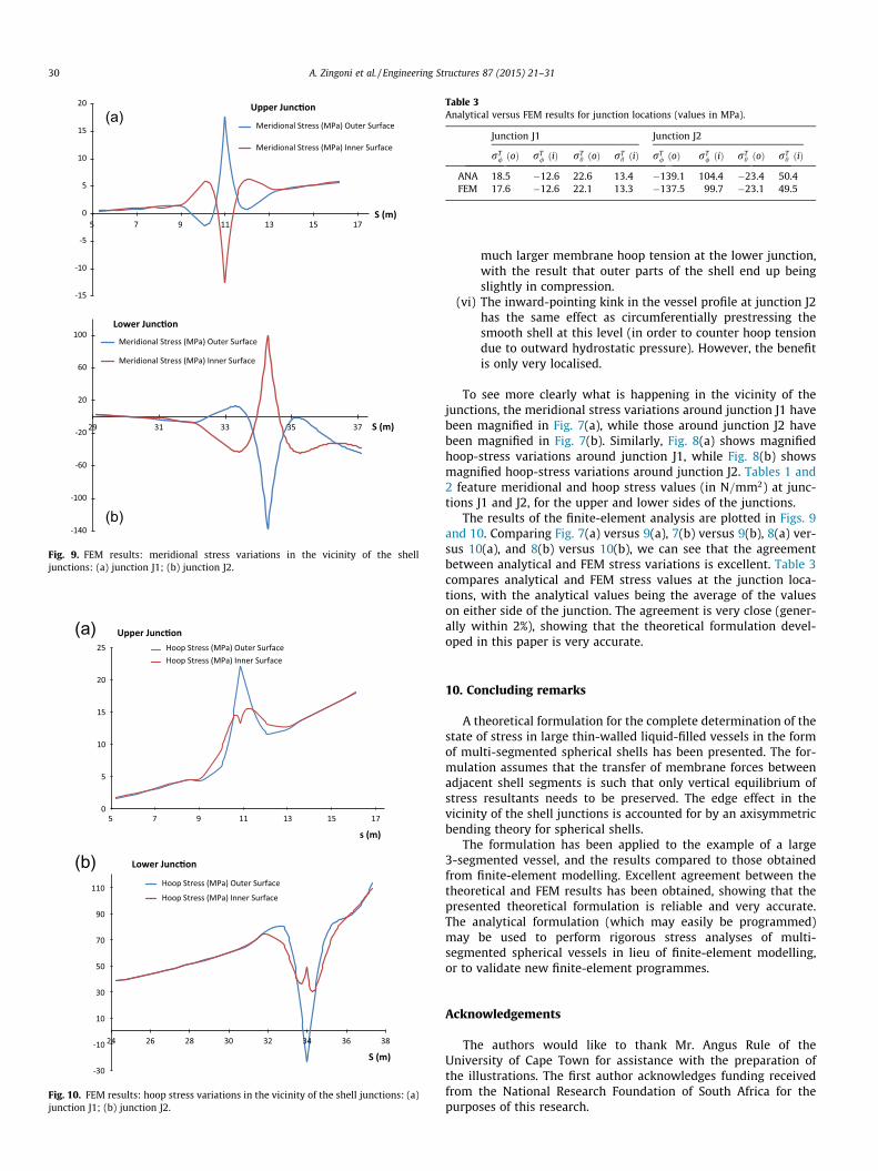
Fig. 9. FEM results: meridional stress variations in the vicinity of the shelljunctions: (a) junction J1; (b) junction J2.
0
5
10
15
20
25
(a)
(b)
5 7 9 11 13 15 17
s (m)
Upper Junc�onHoop Stress (MPa) Outer SurfaceHoop Stress (MPa) Inner Surface
-30
-10
10
30
50
70
90
110
24 26 28 30 32 34 36 38
S (m)
Lower Junc�on
Hoop Stress (MPa) Outer Surface
Hoop Stress (MPa) Inner Surface
Fig. 10. FEM results: hoop stress variations in the vicinity of the shell junctions: (a)junction J1; (b) junction J2.
Table 3Analytical versus FEM results for junction locations (values in MPa).
Junction J1 Junction J2
rT/ ðoÞ rT
/ ðiÞ rTh ðoÞ rT
h ðiÞ rT/ ðoÞ rT
/ ðiÞ rTh ðoÞ rT
h ðiÞ
ANA 18.5 �12.6 22.6 13.4 �139.1 104.4 �23.4 50.4FEM 17.6 �12.6 22.1 13.3 �137.5 99.7 �23.1 49.5
30 A. Zingoni et al. / Engineering Structures 87 (2015) 21–31
much larger membrane hoop tension at the lower junction,with the result that outer parts of the shell end up beingslightly in compression.
(vi) The inward-pointing kink in the vessel profile at junction J2has the same effect as circumferentially prestressing thesmooth shell at this level (in order to counter hoop tensiondue to outward hydrostatic pressure). However, the benefitis only very localised.
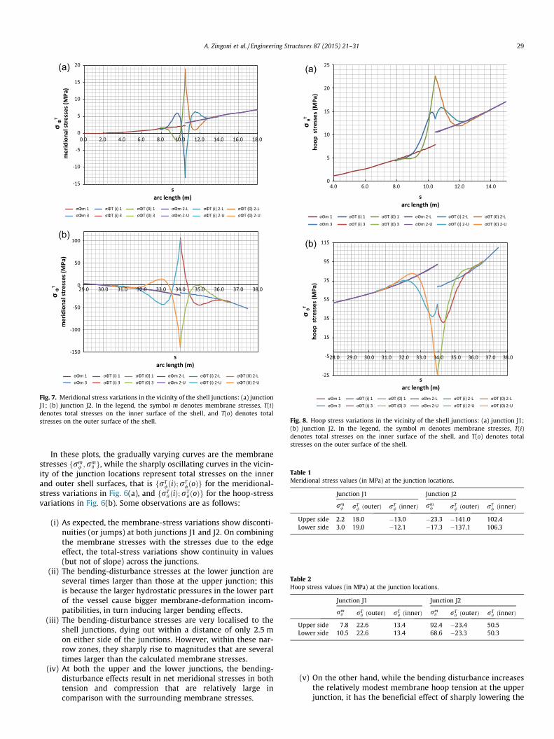
To see more clearly what is happening in the vicinity of thejunctions, the meridional stress variations around junction J1 havebeen magnified in Fig. 7(a), while those around junction J2 havebeen magnified in Fig. 7(b). Similarly, Fig. 8(a) shows magnifiedhoop-stress variations around junction J1, while Fig. 8(b) showsmagnified hoop-stress variations around junction J2. Tables 1 and2 feature meridional and hoop stress values (in N=mm2) at junc-tions J1 and J2, for the upper and lower sides of the junctions.
The results of the finite-element analysis are plotted in Figs. 9and 10. Comparing Fig. 7(a) versus 9(a), 7(b) versus 9(b), 8(a) ver-sus 10(a), and 8(b) versus 10(b), we can see that the agreementbetween analytical and FEM stress variations is excellent. Table 3compares analytical and FEM stress values at the junction loca-tions, with the analytical values being the average of the valueson either side of the junction. The agreement is very close (gener-ally within 2%), showing that the theoretical formulation devel-oped in this paper is very accurate.
10. Concluding remarks
A theoretical formulation for the complete determination of thestate of stress in large thin-walled liquid-filled vessels in the formof multi-segmented spherical shells has been presented. The for-mulation assumes that the transfer of membrane forces betweenadjacent shell segments is such that only vertical equilibrium ofstress resultants needs to be preserved. The edge effect in thevicinity of the shell junctions is accounted for by an axisymmetricbending theory for spherical shells.
The formulation has been applied to the example of a large3-segmented vessel, and the results compared to those obtainedfrom finite-element modelling. Excellent agreement between thetheoretical and FEM results has been obtained, showing that thepresented theoretical formulation is reliable and very accurate.The analytical formulation (which may easily be programmed)may be used to perform rigorous stress analyses of multi-segmented spherical vessels in lieu of finite-element modelling,or to validate new finite-element programmes.
Acknowledgements
The authors would like to thank Mr. Angus Rule of theUniversity of Cape Town for assistance with the preparation ofthe illustrations. The first author acknowledges funding receivedfrom the National Research Foundation of South Africa for thepurposes of this research.
A. Zingoni et al. / Engineering Structures 87 (2015) 21–31 31
References
[1] Tooth AS. Storage vessels. Developments in thin-walled structures, vol.1. London: Elsevier Applied Science; 1982. p. 1–52.
[2] Novozhilov VV. Thin shell theory. Groningen: Wolters-Noordhoff; 1970.[3] Flugge W. Stresses in shells. Berlin: Springer-Verlag; 1973.[4] Gould PL. Analysis of shells and plates. New York: Springer-Verlag; 1988.[5] Zingoni A. Shell structures in civil and mechanical engineering. London: Thomas
Telford; 1997.[6] Bathe KJ. Finite element procedures in engineering analysis. Englewood Cliffs
(NJ): Prentice-Hall; 1982.[7] Gould PL. Finite element analysis of shells of revolution. Pitman Publishing;
1985.[8] Chapelle D, Bathe KJ. The finite element analysis of shells: fundamentals. 2nd
ed. New York: Springer; 2011.[9] Zingoni A. On membrane solutions for elevated shell-of-revolution tanks of
certain meridional profiles. Thin-Wall Struct 1995;22:121–42.[10] Zingoni A. Stress analysis of a storage vessel in the form of a complete triaxial
ellipsoid: hydrostatic effects. Int J Pressure Vessels Piping 1995;62:269–79.[11] Chen L, Rotter JM, Doerich C. Buckling of cylindrical shells with stepwise
variable wall thickness under uniform external pressure. Eng Struct2011;33:3570–8.
[12] Zingoni A, Pavlovic MN. Discontinuity phenomena around the supports ofstepwise-thickened spherical steel tanks: theoretical considerations andparametric results. Int J Pressure Vessels Piping 1993;53:405–35.
[13] Sosa EM, Godoy LA. Challenges in the computation of lower-bound bucklingloads for tanks under wind pressures. Thin-Wall Struct 2010;48:935–45.
[14] Zhao Y, Lin Y. Buckling of cylindrical open-topped steel tanks under wind load.Thin-Wall Struct 2014;79:83–94.
[15] Burgos CA, Jaca RC, Lassig JL, Godoy LA. Wind buckling of tanks with conicalroof considering shielding by another tank. Thin-Wall Struct 2014;84:226–40.
[16] Zhao Y, Lin Y, Shen YB. Wind loads on large cylindrical open-topped tanks ingroup. Thin-Wall Struct 2014;78:108–20.
[17] Shekari MR, Khaji N, Ahmadi MT. On the seismic behavior of cylindrical base-isolated liquid storage tanks excited by long-period ground motions. Soil DynEarthquake Eng 2010;30:968–80.
[18] Ozdemir Z, Souli M, Fahjan YM. Application of nonlinear fluid–structureinteraction methods to seismic analysis of anchored and unanchored tanks.Eng Struct 2010;32:409–23.
[19] Taniguchi T, Ando Y, Nakashima T. Fluid pressure on unanchored rigid flat-bottom cylindrical tanks due to uplift motion and its approximation. EngStruct 2009;31:2598–606.
[20] Guggenberger W. Collapse design of large steel digester tanks. Thin-WallStruct 1994;20:109–28.
[21] Rotter JM. Shell structures: the new European standard and current researchneeds. Thin-Wall Struct 1998;31:3–23.
[22] Rotter JM. Recent advances in the philosophy of the practical design of shellstructures, implemented in Eurocode provisions. In: Zingoni A, editor. Recentdevelopments in structural engineering, mechanics andcomputation. Rotterdam: Millpress; 2007. p. 26–31.
[23] Zingoni A. Stresses and deformations in egg-shaped sludge digesters:membrane effects. Eng Struct 2001;23:1365–72.
[24] Zingoni A. Stresses and deformations in egg-shaped sludge digesters:discontinuity effects. Eng Struct 2001;23:1373–82.
[25] Zingoni A. Parametric stress distribution in shell-of-revolution sludgedigesters of parabolic ogival form. Thin-Wall Struct 2002;40:691–702.
[26] El Damatty AA, Marroquin EG, El Attar M. Behavior of stiffened liquid-filledconical tanks. Thin-Wall Struct 2001;39:353–73.
[27] El Damatty AA, Marroquin E. Design procedure for stiffened water-filled steelconical tanks. Thin-Wall Struct 2002;40:263–82.
[28] Zingoni A. Discontinuity effects at cone–cone axisymmetric shell junctions.Thin-Wall Struct 2002;40:877–91.
[29] Zingoni A. Simplification of the derivation of influence coefficients forsymmetric frusta of shells of revolution. Thin-Wall Struct 2009;47:912–8.
[30] Golzan BS, Showkati H. Buckling of thin-walled conical shells under uniformexternal pressure. Thin-Wall Struct 2008;46:516–29.
[31] Hafeez G, El Ansary AM, El Damatty AA. Stability of combined imperfectconical tanks under hydrostatic loading. J Constr Steel Res 2010;66:1387–97.
[32] Sweedan AMI, El Damatty AA. Simplified procedure for design of liquid-storage combined conical tanks. Thin-Wall Struct 2009;47:750–9.
[33] Jasion P, Magnucki K. Elastic buckling of horizontal barrelled shells filled withliquid: numerical analysis. Thin-Wall Struct 2012;52:117–25.
[34] Zhan HJ, Redekop D. Static and dynamic loading of an ovaloid toroidal tank.Thin-Wall Struct 2009;47:760–7.
[35] Teng JG. Buckling of thin shells: recent advances and trends. Appl Mech Rev(Trans ASME) 1996;49:263–74.
[36] Hetenyi M. Beams on elastic foundation. Ann Arbor: University of MichiganPress; 1946.
[37] ABAQUS Standard. Newark (California): Hibbit, Karlsson and Sorenson Inc:1998.
[38] Zingoni A, Pavlovic MN. On edge-disturbance interaction and decouplingerrors in thin-walled nonshallow spherical-shell frusta. Thin-Wall Struct1992;13:375–86.