a terex company quality paving guide...
TRANSCRIPT

Quality PavingGuide Book
19705 (10/00) Part # 49999-143
A Terex Company

19705 (10/00) - i -
Table of Contents
Introduction ............................................................................................................................................. iii
Basic Functions ......................................................................................................................................... 1
Self-Leveling & Traction Features ......................................................................................................... 2Rubber-Tire Pavers, Track Pavers
Material Feed System ............................................................................................................................... 3Hoppers, Conveyors, Conveyor Flow Gates, Augers
Material Feed Sensors .............................................................................................................................. 4Limit Switch, Proportional Feed Sensor, Sonic Feed Sensor
Screed ...................................................................................................................................................... 5-8Screed Tow Points and Tow Arms, Screed Depth Cranks, Main Screed Crown Control,Vibrators, Screed Heaters
Paving Techniques .................................................................................................................................... 9Factors Affecting the Screed
Paving Speed ........................................................................................................................................... 10Stopping and Starting Paver
Screed Assist System ......................................................................................................................... 12-13Adjusting Screed Assist, Angle -Of-Attack
Screed Reaction Time ............................................................................................................................. 14
Adjusting Mat Thickness (Manual Paving) ......................................................................................... 15Average Depth Method, Desired Yield Method
Strike-Offs and Blades ...................................................................................................................... 16-17Fixed Strike-Offs, Hydraulic Strike-Offs, Vertical Blades, Screeding Blades
Line of Pull .............................................................................................................................................. 18
Main Screed Crown ................................................................................................................................ 19
Head of Material ..................................................................................................................................... 20
Controlling Head of Material ........................................................................................................... 21-25Flow Gates, Spilled Material, Material Feed Sensors, Limit Switch, Limit Switch Setup,Proportional Feed, Proportional Feed Setup, Sonic Feed Control, Sonic Operation, Effect ofHeat Waves, End Gate Mounting, End Gate Setup
Material Design .................................................................................................................................. 26-28Gradation of Material Design, Aggregate Size in relation to Paving Depth, Asphalt Content,Temperature of Material
Rolling (Compaction) ........................................................................................................................ 29-32Temperature Effects, Paving Depth, Pre-Leveling Grade, Stopping Roller, Roller Patterns,Vibratory Roller Travel Speed, Checking Unrolled Mat
Automatic Screed Control ................................................................................................................ 33-37Building Profile, Rideability, Evaluation of Jobs, Basics of Automation, Grade Control,Grade Sensor Deadband, Slope Control, Remote Hand-Held Set Unit, Centering Hand-HeldUnit, Slope Deadband, Setting Deadband
Agetk System Four Settings ............................................................................................................. 38-41Accessing System Four Performance Settings, Operation Checks
Basic Sensor Principles .......................................................................................................................... 42Sensor Positioning

19705 (10/00) - ii -
Table of Contents
Areas Of Deviation ............................................................................................................................ 43-44Tow Point, Screed, Sensor
Sensor Location with Respect to Screed Reaction ......................................................................... 45-49Effective Length of Tow Arm, Screed Mounting, Grade Control for Joint Matching, GradeControl for Fixed Stringline, Grade Control for a Ski, Types of Skis, Traveling Stringline
Slope Control System ........................................................................................................................ 50-52Sensor Positioning, Building For Rideability, Building For Profile
Reactions (Combinations of Grade and Slope) .............................................................................. 53-54Ski and Slope (forward and rearward), Joint Matcher and Slope (forward and rearward)
SMOOTHTRAC™ Sonic Averaging System (SAS) ..................................................................... 55-69Installation, Assembly, Setup, & Operation
Slope Conversion Table ......................................................................................................................... 70
Operation ................................................................................................................................................. 71Nulling Screed
Joints ................................................................................................................................................... 72-74Transverse Joints, Longitudinal Joints, Using Automatics
Segregation ......................................................................................................................................... 74-75Segregation before Paver, Segregation in Truck, Segregation Stripe, Pre-Compaction Stripe
Troubleshooting Guide ..................................................................................................................... 76-80
Paving Terminology .......................................................................................................................... 81-82
CIMA Information ............................................................................................................................ 83-89Asphalt Paver Component Nomenclature List, Rubber-Tire and Crawler Paver Diagrams
19705 (10/00) - iii -
SAFETY INSTRUCTIONS
Federal, state and local safety regulations must becomplied with to prevent possible danger to person(s)or property from accidents or harmful exposure.
This equipment must be used in accordance withall operation and maintenance instructions.
We strongly recommend that all persons involvedwith this equipment be familiar with this manual,operation and maintenance manual and all relatedengine manuals.
• Read all warning, caution and instruction signs.
• Know what guards and protective devices areincluded and see that each is used. Additionalguards and protective devises that may be requireddue to the various paver configurations must beinstalled by the user (owner) before operating.
• Install all auger guards and vibrator covers beforeoperating the paver.
• Never attempt to install or remove any part orassembly when the paver is running.
IntroductionThis information should provide a clear understanding of equipment construction,
function, capabilities and requirements.
The information is based on the knowledge and experience of highly qualified peopleat Cedarapids Inc. Proper use of this information will promote high efficiency, maximumservice life and low maintenance costs.
The information contained in this manual should not be considered all-inclusive forevery application. Questions about specific uses of this equipment should be directed toCedarapids Inc.
Using this equipment for any purpose other than its intended use assumes the risk of anydanger in doing so.
Respectfully,Cedarapids Inc.
• Wear a protective mask when harmful air pollutionexists.
• Wear clothing that fits snug to prevent gettingcaught in moving parts. Loose-fitting clothingshould not be worn.
• Wear safety goggles, gloves and long-sleeve shirtswhen in close proximity of hot asphalt materials.
• Wear ear plugs if needed.
• Mount and dismount the paver from the rear usingonly the steps, handrails and walkways provided.
• Allow the operator only on the operator’s platformwhen the paver is in operation.
• Before starting the paver, make sure the brakes arein the ON position, all other systems are in the OFFposition and all personnel are clear of the paver.
• Allow the operator only on the paver whentraveling or roading.
19705 (10/00) - iv -
• Before leaving the operator’s seat always place thebrake switch ON and all other controls and switchesin the OFF or NEUTRAL position.
• Reduce travel speed when going down steep gradesto prevent over-speeding.
• Keep operator’s platform, steps and screedwalkways clear of all obstructions (tools, lunchboxes, rakes, shovels, etc. to prevent tripping orfalling.
• Keep all personnel clear of paver when operating.
• Do not allow personnel near the hopper area whenthe paver running.
• Do not allow personnel to walk between the paverand truck.
• To prevent injuries, screed safety cables andadditional blocking beneath the screed must beused before any checks or adjustments are made.
• Keep all personnel clear of augers and screed whenthe paver is operating.
• Do not refuel the paver with the engine or screedheater system running. All sparks and open flamesmust be kept a minimum of 50 feet away from thepaver when refueling.
• Do not wash or spray down the screed with thescreed heater system operating.
• To prevent fire hazards, keep the basket area of thetractor free of oil, fuel and trash buildup.
• To prevent fire hazards, keep the screed free of oil,asphalt and trash buildup to prevent fire hazards.
19705 (10/00) - 1 -
Quality Paving Guidebook
A Terex Company
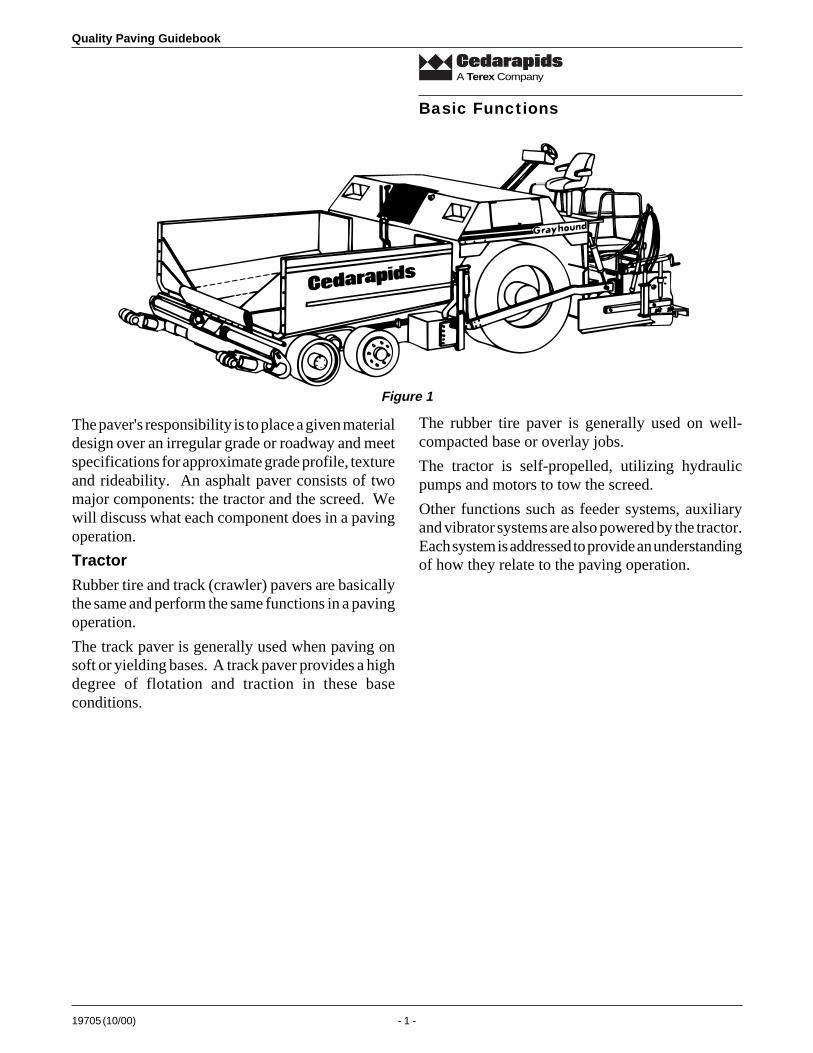
The paver's responsibility is to place a given materialdesign over an irregular grade or roadway and meetspecifications for approximate grade profile, textureand rideability. An asphalt paver consists of twomajor components: the tractor and the screed. Wewill discuss what each component does in a pavingoperation.
Tractor
Rubber tire and track (crawler) pavers are basicallythe same and perform the same functions in a pavingoperation.
The track paver is generally used when paving onsoft or yielding bases. A track paver provides a highdegree of flotation and traction in these baseconditions.
Basic Functions
The rubber tire paver is generally used on well-compacted base or overlay jobs.
The tractor is self-propelled, utilizing hydraulicpumps and motors to tow the screed.
Other functions such as feeder systems, auxiliaryand vibrator systems are also powered by the tractor.Each system is addressed to provide an understandingof how they relate to the paving operation.
Figure 1
Quality Paving Guidebook
19705 (10/00) - 2 -
A Terex Company
Self-Leveling &Traction Features
Pull Point
Line of Pull
Pivot
Front Bogies PivotDrive wheels can moveindependent of each other
Line of Pull
Pull Point
PivotPivot
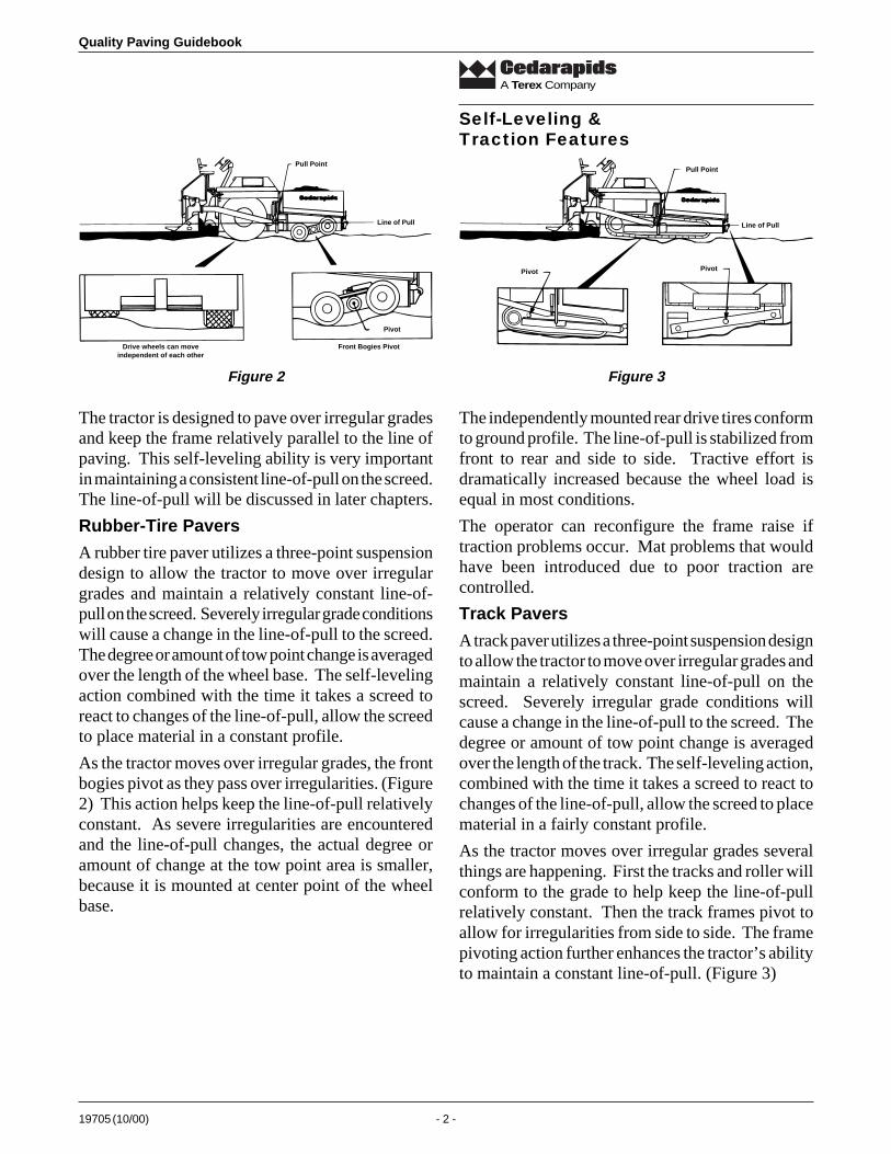
The tractor is designed to pave over irregular gradesand keep the frame relatively parallel to the line ofpaving. This self-leveling ability is very importantin maintaining a consistent line-of-pull on the screed.The line-of-pull will be discussed in later chapters.
Rubber-Tire Pavers
A rubber tire paver utilizes a three-point suspensiondesign to allow the tractor to move over irregulargrades and maintain a relatively constant line-of-pull on the screed. Severely irregular grade conditionswill cause a change in the line-of-pull to the screed.The degree or amount of tow point change is averagedover the length of the wheel base. The self-levelingaction combined with the time it takes a screed toreact to changes of the line-of-pull, allow the screedto place material in a constant profile.
As the tractor moves over irregular grades, the frontbogies pivot as they pass over irregularities. (Figure2) This action helps keep the line-of-pull relativelyconstant. As severe irregularities are encounteredand the line-of-pull changes, the actual degree oramount of change at the tow point area is smaller,because it is mounted at center point of the wheelbase.
The independently mounted rear drive tires conformto ground profile. The line-of-pull is stabilized fromfront to rear and side to side. Tractive effort isdramatically increased because the wheel load isequal in most conditions.
The operator can reconfigure the frame raise iftraction problems occur. Mat problems that wouldhave been introduced due to poor traction arecontrolled.
Track Pavers
A track paver utilizes a three-point suspension designto allow the tractor to move over irregular grades andmaintain a relatively constant line-of-pull on thescreed. Severely irregular grade conditions willcause a change in the line-of-pull to the screed. Thedegree or amount of tow point change is averagedover the length of the track. The self-leveling action,combined with the time it takes a screed to react tochanges of the line-of-pull, allow the screed to placematerial in a fairly constant profile.
As the tractor moves over irregular grades severalthings are happening. First the tracks and roller willconform to the grade to help keep the line-of-pullrelatively constant. Then the track frames pivot toallow for irregularities from side to side. The framepivoting action further enhances the tractor’s abilityto maintain a constant line-of-pull. (Figure 3)
Figure 2 Figure 3
19705 (10/00) - 3 -
Quality Paving Guidebook
A Terex Company
Material Feed System
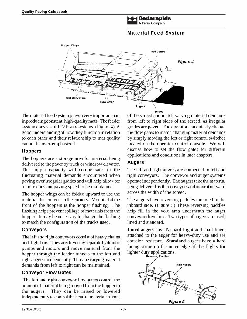
The material feed system plays a very important partin producing constant, high-quality mats. The feedersystem consists of FIVE sub-systems. (Figure 4) Agood understanding of how they function in relationto each other and their relationship to mat qualitycannot be over-emphasized.
Hoppers
The hoppers are a storage area for material beingdelivered to the paver by truck or windrow elevator.The hopper capacity will compensate for thefluctuating material demands encountered whenpaving over irregular grades and will help allow fora more constant paving speed to be maintained.
The hopper wings can be folded upward to use thematerial that collects in the corners. Mounted at thefront of the hoppers is the hopper flashing. Theflashing helps prevent spillage of materials from thehopper. It may be necessary to change the flashingto match the configuration of the trucks used.
Conveyors
The left and right conveyors consist of heavy chainsand flight bars. They are driven by separate hydraulicpumps and motors and move material from thehopper through the feeder tunnels to the left andright augers independently. Thus the varying materialdemands from left to right can be maintained.
Conveyor Flow Gates
The left and right conveyor flow gates control theamount of material being moved from the hopper tothe augers. They can be raised or loweredindependently to control the head of material in front
of the screed and match varying material demandsfrom left to right sides of the screed, as irregulargrades are paved. The operator can quickly changethe flow gates to match changing material demandsby simply moving the left or right control switcheslocated on the operator control console. We willdiscuss how to set the flow gates for differentapplications and conditions in later chapters.
Augers
The left and right augers are connected to left andright conveyors. The conveyor and auger systemsoperate independently. The augers take the materialbeing delivered by the conveyors and move it outwardacross the width of the screed.
The augers have reversing paddles mounted in theinboard side. (Figure 5) These reversing paddleshelp fill in the void area underneath the augerconveyor drive box. Two types of augers are used,lined and standard.
Lined augers have Ni-hard flight and shaft linersattached to the auger for heavy-duty use and areabrasion resistant. Standard augers have a hardfacing stripe on the outer edge of the flights forlighter duty applications.
Feed Control
Screed
Augers
Flow Gates
Slat Conveyors
Hopper Wings
Figure 4
Figure 5
Main Augers
Reversing Paddles
Quality Paving Guidebook
19705 (10/00) - 4 -
A Terex Company
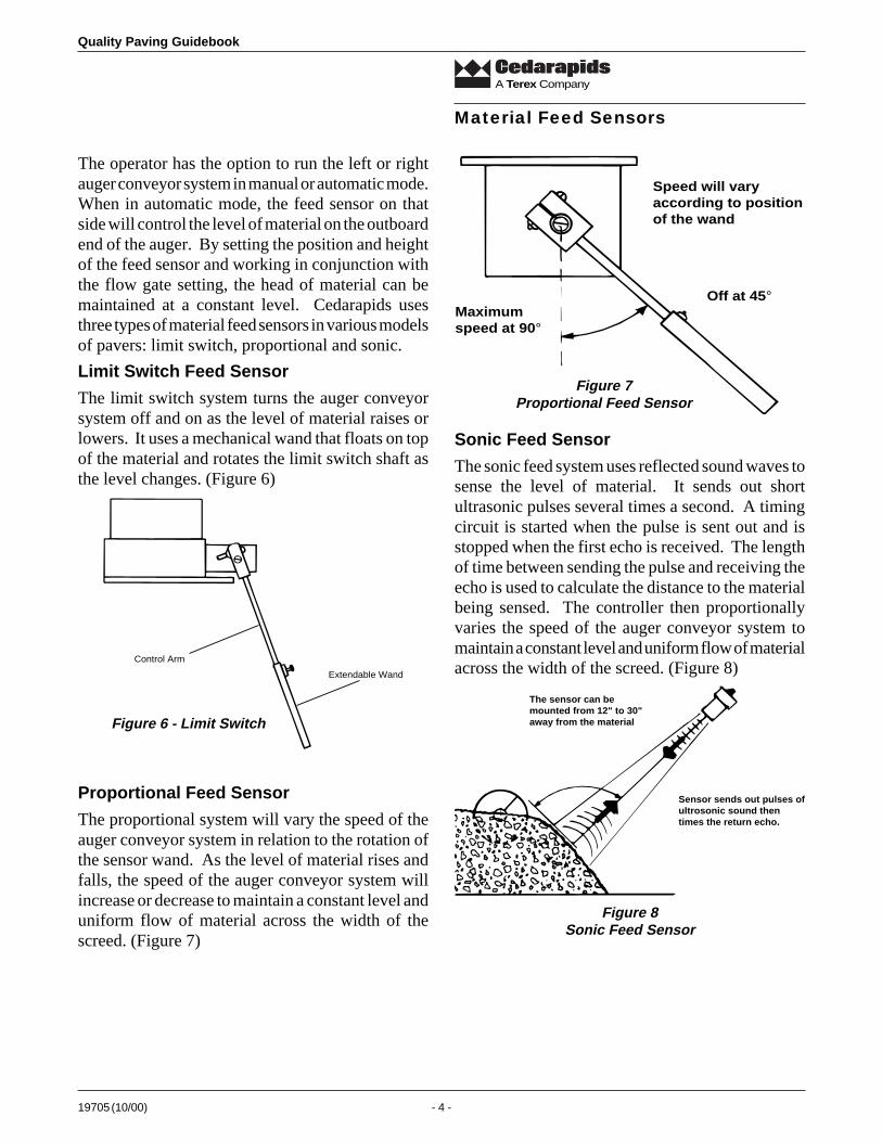
The operator has the option to run the left or rightauger conveyor system in manual or automatic mode.When in automatic mode, the feed sensor on thatside will control the level of material on the outboardend of the auger. By setting the position and heightof the feed sensor and working in conjunction withthe flow gate setting, the head of material can bemaintained at a constant level. Cedarapids usesthree types of material feed sensors in various modelsof pavers: limit switch, proportional and sonic.
Limit Switch Feed Sensor
The limit switch system turns the auger conveyorsystem off and on as the level of material raises orlowers. It uses a mechanical wand that floats on topof the material and rotates the limit switch shaft asthe level changes. (Figure 6)
Material Feed Sensors
Control Arm
Extendable Wand
Proportional Feed Sensor
The proportional system will vary the speed of theauger conveyor system in relation to the rotation ofthe sensor wand. As the level of material rises andfalls, the speed of the auger conveyor system willincrease or decrease to maintain a constant level anduniform flow of material across the width of thescreed. (Figure 7)
Speed will varyaccording to positionof the wand
Maximum speed at 90°
Off at 45°
Sonic Feed Sensor
The sonic feed system uses reflected sound waves tosense the level of material. It sends out shortultrasonic pulses several times a second. A timingcircuit is started when the pulse is sent out and isstopped when the first echo is received. The lengthof time between sending the pulse and receiving theecho is used to calculate the distance to the materialbeing sensed. The controller then proportionallyvaries the speed of the auger conveyor system tomaintain a constant level and uniform flow of materialacross the width of the screed. (Figure 8)
The sensor can bemounted from 12" to 30"away from the material
Sensor sends out pulses ofultrosonic sound then times the return echo.
Figure 8Sonic Feed Sensor
Figure 6 - Limit Switch
Figure 7Proportional Feed Sensor
19705 (10/00) - 5 -
Quality Paving Guidebook
A Terex Company
Screed
Tow Point
Line of Pull
Screed Pull Arm
Screed
Tow Point Cylinder
Figure 9
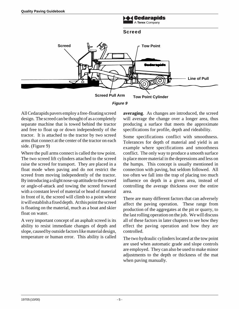
All Cedarapids pavers employ a free-floating screeddesign. The screed can be thought of as a completelyseparate machine that is towed behind the tractorand free to float up or down independently of thetractor. It is attached to the tractor by two screedarms that connect at the center of the tractor on eachside. (Figure 9)
Where the pull arms connect is called the tow point.The two screed lift cylinders attached to the screedraise the screed for transport. They are placed in afloat mode when paving and do not restrict thescreed from moving independently of the tractor.By introducing a slight nose-up attitude to the screedor angle-of-attack and towing the screed forwardwith a constant level of material or head of materialin front of it, the screed will climb to a point whereit will establish a fixed depth. At this point the screedis floating on the material, much as a boat and skierfloat on water.
A very important concept of an asphalt screed is itsability to resist immediate changes of depth andslope, caused by outside factors like material design,temperature or human error. This ability is called
averaging. As changes are introduced, the screedwill average the change over a longer area, thusproducing a surface that meets the approximatespecifications for profile, depth and rideability.
Some specifications conflict with smoothness.Tolerances for depth of material and yield is anexample where specifications and smoothnessconflict. The only way to produce a smooth surfaceis place more material in the depressions and less onthe humps. This concept is usually mentioned inconnection with paving, but seldom followed. Alltoo often we fall into the trap of placing too muchinfluence on depth in a given area, instead ofcontrolling the average thickness over the entirearea.
There are many different factors that can adverselyaffect the paving operation. These range fromproduction of the aggregates at the pit or quarry, tothe last rolling operation on the job. We will discussall of these factors in later chapters to see how theyeffect the paving operation and how they arecontrolled.
The two hydraulic cylinders located at the tow pointare used when automatic grade and slope controlsare employed. They can also be used to make minoradjustments to the depth or thickness of the matwhen paving manually.
Quality Paving Guidebook
19705 (10/00) - 6 -
A Terex Company
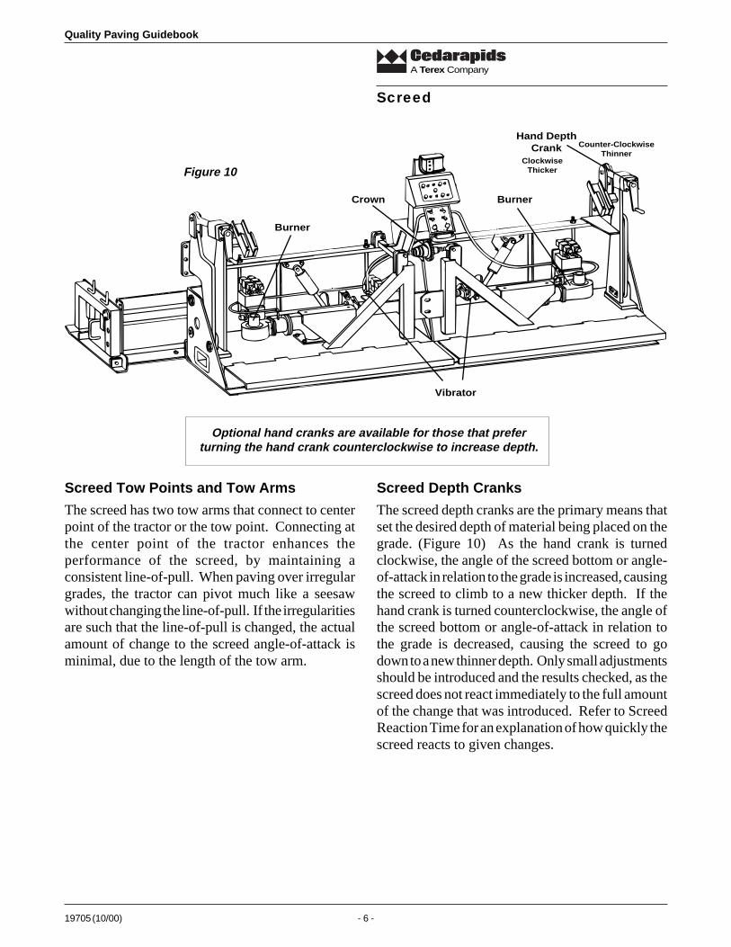
Optional hand cranks are available for those that preferturning the hand crank counterclockwise to increase depth.
Screed Tow Points and Tow Arms
The screed has two tow arms that connect to centerpoint of the tractor or the tow point. Connecting atthe center point of the tractor enhances theperformance of the screed, by maintaining aconsistent line-of-pull. When paving over irregulargrades, the tractor can pivot much like a seesawwithout changing the line-of-pull. If the irregularitiesare such that the line-of-pull is changed, the actualamount of change to the screed angle-of-attack isminimal, due to the length of the tow arm.
Screed Depth Cranks
The screed depth cranks are the primary means thatset the desired depth of material being placed on thegrade. (Figure 10) As the hand crank is turnedclockwise, the angle of the screed bottom or angle-of-attack in relation to the grade is increased, causingthe screed to climb to a new thicker depth. If thehand crank is turned counterclockwise, the angle ofthe screed bottom or angle-of-attack in relation tothe grade is decreased, causing the screed to godown to a new thinner depth. Only small adjustmentsshould be introduced and the results checked, as thescreed does not react immediately to the full amountof the change that was introduced. Refer to ScreedReaction Time for an explanation of how quickly thescreed reacts to given changes.
Screed
Hand DepthCrank
Crown
Burner
Burner
Vibrator
ClockwiseThicker
Counter-ClockwiseThinner
Figure 10

19705 (10/00) - 7 -
Quality Paving Guidebook
A Terex Company
Amplitude Setting
The smaller the anglethe higher the amplitude
120°
Clockwise rotation of the knobincreases VPM.Counterclockwise rotationdecreases VPM.
VibratorSpeed Control
Screed
3" MaximumPositive Crown
1" MaximumNegative Crown
Main Screed Crown Control
The main screed crown control allows the screedbottom to be set to a flat profile, or be bent to matchspecifications for various road profiles. The crowncan be set from a 1 inch negative to a 3 inch positivecrown over 10 feet. (Figure 11)
Vibrators
The vibrators mounted on the screed rearrangeparticles and aggregates in the material being placedso the texture is more uniform. Approximately 80%to 85% of the theoretical maximum density is usuallyachieved by the screed.
The actual density achieved by a given screed isdependent on: (a) the amount of bearing pressureapplied to the material by the screed; (b) mix design;
(c) percent of asphalt; (d) temperature (mix, groundand ambient); (e) depth of material; and (f) gradeconditions.
The vibrators can be adjusted for both VPM(vibration-per-minute) and amplitude (amount offorce imparted from the screed to the material).
VPM is adjusted by turning a control valve locatedon the screed. Clockwise rotation increases VPM,while counterclockwise rotation decreases VPM.(Figure 12)
The amplitude is changed by relocating theorientation of the eccentric weights located on thevibrator shaft. (Figure 13)
Figure 11
Figure 12
Figure 13
Quality Paving Guidebook
19705 (10/00) - 8 -
A Terex Company
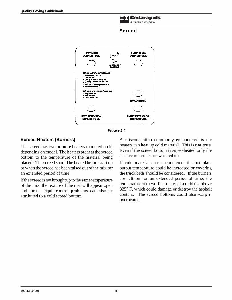
Screed Heaters (Burners)
The screed has two or more heaters mounted on it,depending on model. The heaters preheat the screedbottom to the temperature of the material beingplaced. The screed should be heated before start upor when the screed has been raised out of the mix foran extended period of time.
If the screed is not brought up to the same temperatureof the mix, the texture of the mat will appear openand torn. Depth control problems can also beattributed to a cold screed bottom.
A misconception commonly encountered is theheaters can heat up cold material. This is not true.Even if the screed bottom is super-heated only thesurface materials are warmed up.
If cold materials are encountered, the hot plantoutput temperature could be increased or coveringthe truck beds should be considered. If the burnersare left on for an extended period of time, thetemperature of the surface materials could rise above325° F, which could damage or destroy the asphaltcontent. The screed bottoms could also warp ifoverheated.
Screed
Figure 14
19705 (10/00) - 9 -
Quality Paving Guidebook
A Terex Company
Paving Techniques
Factors Affecting the Screed
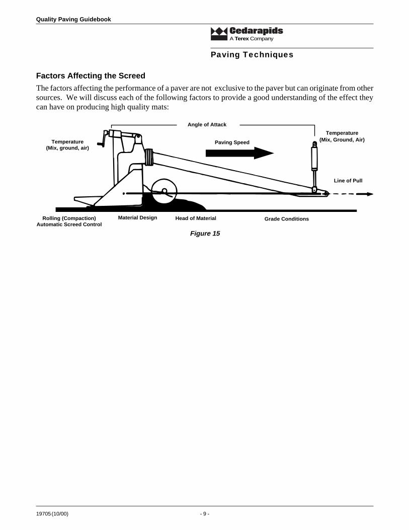
The factors affecting the performance of a paver are not exclusive to the paver but can originate from othersources. We will discuss each of the following factors to provide a good understanding of the effect theycan have on producing high quality mats:
Temperature(Mix, Ground, Air)
Angle of Attack
Material Design Head of Material Grade Conditions
Line of Pull
Paving Speed
Rolling (Compaction)Automatic Screed Control
Temperature(Mix, ground, air)
Figure 15
Quality Paving Guidebook
19705 (10/00) - 10 -
A Terex Company
Paving Speed
The contractor must get increased production forevery hour worked without loss of quality. So apaver must place every ounce of material deliveredto it while maintaining top quality. To do thisconsistently a few things must be taken into account:
1) The tonnage output of the hot plant has to beknown. Remember, the output rate can changedue to outside factors such as the amount ofmoisture in the stock pile.
2) Take into account the method used to delivermaterial to the paver. This includes the numberof trucks, size of trucks, distance from plant topaver and traffic conditions.
3) Know the paving width and depth. Use thechart in this section to calculate the paverspeed required to place the material.
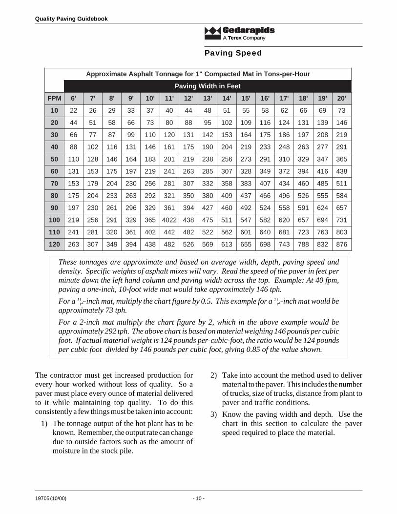
These tonnages are approximate and based on average width, depth, paving speed anddensity. Specific weights of asphalt mixes will vary. Read the speed of the paver in feet perminute down the left hand column and paving width across the top. Example: At 40 fpm,paving a one-inch, 10-foot wide mat would take approximately 146 tph.
For a 1¦2-inch mat, multiply the chart figure by 0.5. This example for a 1¦2-inch mat would beapproximately 73 tph.
For a 2-inch mat multiply the chart figure by 2, which in the above example would beapproximately 292 tph. The above chart is based on material weighing 146 pounds per cubicfoot. If actual material weight is 124 pounds per-cubic-foot, the ratio would be 124 poundsper cubic foot divided by 146 pounds per cubic foot, giving 0.85 of the value shown.
ruoH-rep-snoTnitaMdetcapmoC"1rofegannoTtlahpsAetamixorppA
teeFnihtdiWgnivaP
MPF '6 '7 '8 '9 '01 '11 '21 '31 '41 '51 '61 '71 '81 '91 '02
01 22 62 92 33 73 04 44 84 15 55 85 26 66 96 37
02 44 15 85 66 37 08 88 59 201 901 611 421 131 931 641
03 66 77 78 99 011 021 131 241 351 461 571 681 791 802 912
04 88 201 611 131 641 161 571 091 402 912 332 842 362 772 192
05 011 821 641 461 381 102 912 832 652 372 192 013 923 743 563
06 131 351 571 791 912 142 362 582 703 823 943 273 493 614 834
07 351 971 402 032 652 182 703 233 853 383 704 434 064 584 115
08 571 402 332 362 292 123 053 083 904 734 664 694 625 555 485
09 791 032 162 692 923 163 493 724 064 294 425 855 195 426 756
001 912 652 192 923 563 2204 834 574 115 745 285 026 756 496 137
011 142 182 023 163 204 244 284 225 265 106 046 186 327 367 308
021 362 703 943 493 834 284 625 965 316 556 896 347 887 238 678
19705 (10/00) - 11 -
Quality Paving Guidebook
A Terex Company
Paving Speed
Speed is consistent
Uniform Density
Consistent Depth
Speed Increase
Depth Decrease
Density Change Occurs
Speed Decrease
Depth Increase
Density Change Occurs
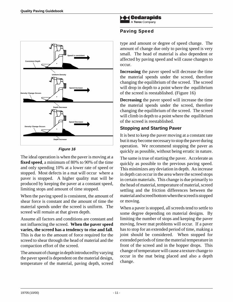
type and amount or degree of speed change. Theamount of change due only to paving speed is verysmall. The head of material is also dependent oraffected by paving speed and will cause changes tooccur.
Increasing the paver speed will decrease the timethe material spends under the screed, thereforechanging the equilibrium of the screed. The screedwill drop in depth to a point where the equilibriumof the screed is reestablished. (Figure 16)
Decreasing the paver speed will increase the timethe material spends under the screed, thereforechanging the equilibrium of the screed. The screedwill climb in depth to a point where the equilibriumof the screed is reestablished.
Stopping and Starting Paver
It is best to keep the paver moving at a constant ratebut it may become necessary to stop the paver duringoperation. We recommend stopping the paver asquickly as possible, without being erratic in nature.
The same is true of starting the paver. Accelerate asquickly as possible to the previous paving speed.This minimizes any deviation in depth. An increasein depth can occur in the area where the screed stopsin certain materials. This change is due primarily tothe head of material, temperature of material, screedsettling and the friction differences between thematerial and screed bottom when the screed is stoppedor moving.
When a paver is stopped, all screeds tend to settle tosome degree depending on material designs. Bylimiting the number of stops and keeping the pavermoving, fewer mat problems will occur. If a paverhas to stop for an extended period of time, making ajoint should be considered. When stopped forextended periods of time the material temperature infront of the screed and in the hopper drops. Thischange of temperature will cause a texture change tooccur in the mat being placed and also a depthchange.
The ideal operation is when the paver is moving at afixed speed, a minimum of 80% to 90% of the timeand only spending 10% at a lower rate of speed orstopped. Most defects in a mat will occur where apaver is stopped. A higher quality mat will beproduced by keeping the paver at a constant speed,limiting stops and amount of time stopped.
When the paving speed is consistent, the amount ofshear force is constant and the amount of time thematerial spends under the screed is uniform. Thescreed will remain at that given depth.
Assume all factors and conditions are constant andnot influencing the screed. When the paver speedvaries, the screed has a tendency to rise and fall.This is due to the amount of force required for thescreed to shear through the head of material and thecompaction effort of the screed.
The amount of change in depth introduced by varyingthe paver speed is dependent on the material design,temperature of the material, paving depth, screed
Figure 16
Quality Paving Guidebook
19705 (10/00) - 12 -
A Terex Company
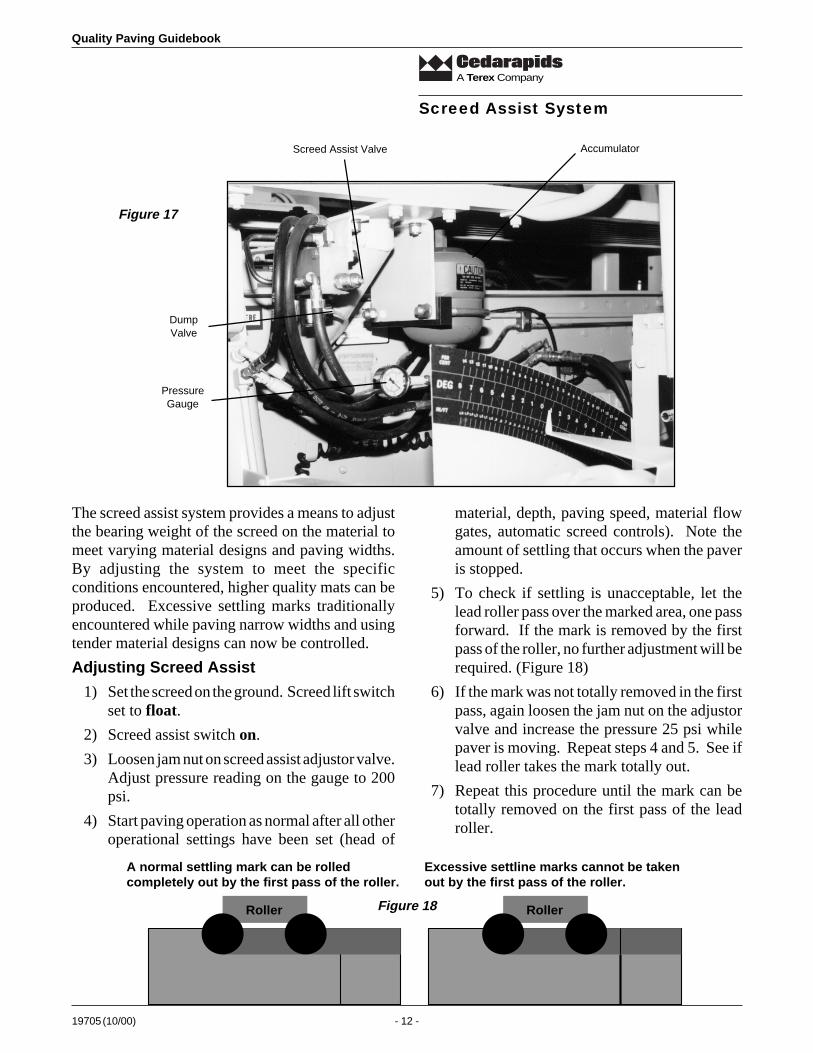
Screed Assist Valve Accumulator
PressureGauge
DumpValve
The screed assist system provides a means to adjustthe bearing weight of the screed on the material tomeet varying material designs and paving widths.By adjusting the system to meet the specificconditions encountered, higher quality mats can beproduced. Excessive settling marks traditionallyencountered while paving narrow widths and usingtender material designs can now be controlled.
Adjusting Screed Assist
1) Set the screed on the ground. Screed lift switchset to float.
2) Screed assist switch on.
3) Loosen jam nut on screed assist adjustor valve.Adjust pressure reading on the gauge to 200psi.
4) Start paving operation as normal after all otheroperational settings have been set (head of
material, depth, paving speed, material flowgates, automatic screed controls). Note theamount of settling that occurs when the paveris stopped.
5) To check if settling is unacceptable, let thelead roller pass over the marked area, one passforward. If the mark is removed by the firstpass of the roller, no further adjustment will berequired. (Figure 18)
6) If the mark was not totally removed in the firstpass, again loosen the jam nut on the adjustorvalve and increase the pressure 25 psi whilepaver is moving. Repeat steps 4 and 5. See iflead roller takes the mark totally out.
7) Repeat this procedure until the mark can betotally removed on the first pass of the leadroller.
Screed Assist System
Roller Roller
A normal settling mark can be rolledcompletely out by the first pass of the roller.
Excessive settline marks cannot be takenout by the first pass of the roller.
Figure 17
Figure 18
19705 (10/00) - 13 -
Quality Paving Guidebook
A Terex Company
The Dump Valve should remain closed at alltimes. It is provided to dump pressure from thesystem, so it can be worked on safely by themechanics.
Do not switch the screed assist system off and onduring a paving operation. This will cause matdefects.
Do not use any more pressure than required tocontrol settling or the screed may have a tendency toride on its nose. This could cause other mat problems.
Rule of Thumb Higher pressure is required fornarrow-width paving (under 12 feet wide), lowerpressure is required for wide-width paving (beyond12 feet wide).
Screed Assist System
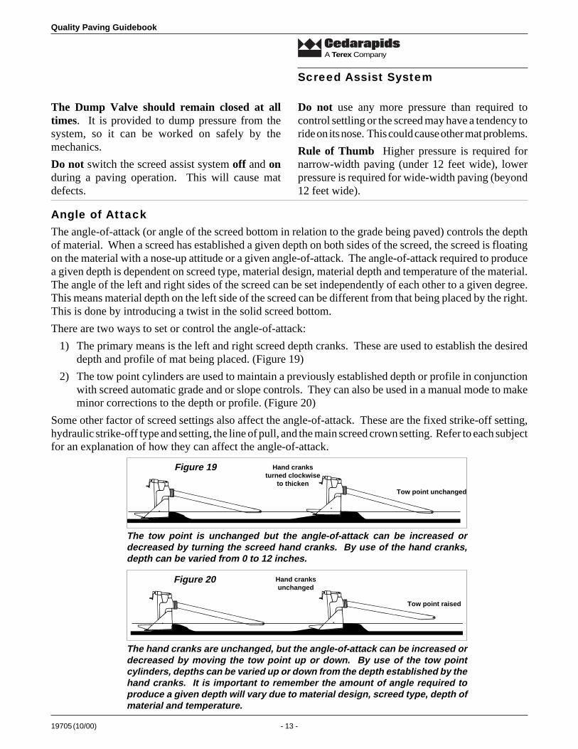
The angle-of-attack (or angle of the screed bottom in relation to the grade being paved) controls the depthof material. When a screed has established a given depth on both sides of the screed, the screed is floatingon the material with a nose-up attitude or a given angle-of-attack. The angle-of-attack required to producea given depth is dependent on screed type, material design, material depth and temperature of the material.The angle of the left and right sides of the screed can be set independently of each other to a given degree.This means material depth on the left side of the screed can be different from that being placed by the right.This is done by introducing a twist in the solid screed bottom.
There are two ways to set or control the angle-of-attack:
1) The primary means is the left and right screed depth cranks. These are used to establish the desireddepth and profile of mat being placed. (Figure 19)
2) The tow point cylinders are used to maintain a previously established depth or profile in conjunctionwith screed automatic grade and or slope controls. They can also be used in a manual mode to makeminor corrections to the depth or profile. (Figure 20)
Some other factor of screed settings also affect the angle-of-attack. These are the fixed strike-off setting,hydraulic strike-off type and setting, the line of pull, and the main screed crown setting. Refer to each subjectfor an explanation of how they can affect the angle-of-attack.
Tow point unchanged
Hand cranksturned clockwise
to thicken
The tow point is unchanged but the angle-of-attack can be increased ordecreased by turning the screed hand cranks. By use of the hand cranks,depth can be varied from 0 to 12 inches.
Tow point raised
Hand cranksunchanged
The hand cranks are unchanged, but the angle-of-attack can be increased ordecreased by moving the tow point up or down. By use of the tow pointcylinders, depths can be varied up or down from the depth established by thehand cranks. It is important to remember the amount of angle required toproduce a given depth will vary due to material design, screed type, depth ofmaterial and temperature.
Figure 19
Figure 20
Angle of Attack

Quality Paving Guidebook
19705 (10/00) - 14 -
A Terex Company
First length 60-65% The next four lengths the remaining 30 - 35%
Five lengths of tow arm are required for correction to be completed
Screed reaction time refers to the amount of timerequired for a screed to complete a change in depththat was introduced by the screed depth cranks or bya change in position of the tow points.
As shown in figure 21, a given downward changewas introduced to the angle-of-attack. If no otherchanges are introduced, the screed will decrease indepth approximately 60% to 65% of the total amountof change in the first length of the tow arm. As thescreed travels four more lengths of the tow arm, theremaining 30% to 35% of the total change willoccur.
The reason the screed completes 60% to 65% of thetotal change in the first length of the tow arm andthen takes four more lengths of the tow arm to
Screed Reaction Time
Screed pivots aroundtow point
complete the remaining 30% to 35% is because thescreed actually pivots around the tow point. (Figure23) When the angle-of-attack is increased from agiven depth, the higher angle-of-attack will allowmore material to meter under the screed, causing itto start climbing. As the screed climbs, the newhigher angle-of-attack starts decreasing and theamount of material metered under the screeddecreases, causing the rate of climb to decrease. Thenew angle-of-attack established at the end of fivelengths of the tow arm will be slightly larger thanthat required at the thinner depth. (Figure 22)
Original Angle Increased Angle New angle is slightlylarger than original
Crank is turnedclockwise
The actual angle-of-attack required for a specificdepth is dependent on the material design,temperature of the material, depth of material andscreed type. Course, dense material designs willrequire a smaller angle-of-attack to produce a givendepth in comparison to a fine graded or sandymaterial design. This is due to the compaction ratesof the various material designs.
Normal angleof attack is 1/8" to1/4" for best mattexture.
A screed should run with a 1¦8 inch to 1¦4 inch nose-upattitude or angle-of-attack. (Figure 24) When runningin this range the full width of the screed bottom isutilized to produce the best possible mat texture. Ifthe screed is allowed to run at extremes of increasedor decreased angle-of-attack, poor mat texture willresult. In these conditions, only a small portion ofthe screed bottom is utilized for compaction andtexture, decreasing the life of the screed bottom.
Figure 21
Figure 22
Figure 23
Figure 24
19705 (10/00) - 15 -
Quality Paving Guidebook
A Terex Company
Our objective is to place a smooth, uniform asphaltmat over an irregular grade. When paving manually,we do not have the advantage of screed automationcontrolling depth adjustments for us. This control isin the hands of the screed operator. He has toevaluate the grade conditions and specifications orrequirements of the job. Factors of average depth,yield, profile and slope become a big concern asmost manual paving jobs will not allow for morematerial to be placed than what was estimated or bidon. To be able to place a smooth, uniform mat overirregular grades and control yield, we have to be ableto check and control our material usage. There aretwo ways to do this.
Average Depth Method
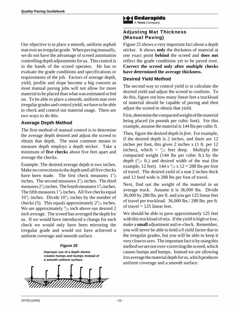
The first method of manual control is to determinethe average depth desired and adjust the screed toobtain that depth. The most common means tomeasure depth employs a depth sticker. Take aminimum of five checks about five feet apart andaverage the checks.
Example: The desired average depth is two inches.Make no corrections to the depth until all five checkshave been made. The first check measures 17¦8inches. The second measures 27¦8 inches. The thirdmeasures 21¦8 inches. The fourth measures 13¦4 inches.The fifth measures 17¦8 inches. All five checks equal101¦2 inches. Divide 101¦2 inches by the number ofchecks (5). This equals approximately 23¦32 inches.We are approximately 3¦32 inch above our desired 2inch average. The screed has averaged the depth forus. If we would have introduced a change for eachcheck we would only have been mirroring theirregular grade and would not have achieved auniform coverage and smooth surface.
Adjusting Mat Thickness(Manual Paving)Figure 25 shows a very important fact about a depthsticker. It shows only the thickness of material atone exact point behind the screed and does notreflect the grade conditions yet to be paved over.Correct the screed only after multiple checkshave determined the average thickness.
Desired Yield Method
The second way to control yield is to calculate thedesired yield and adjust the screed to conform. Todo this, figure out how many linear feet a truckloadof material should be capable of paving and thenadjust the screed to obtain that yield.
First, determine the compacted weight of the materialbeing placed (in pounds per cubic foot). For thisexample, assume the material is 144 lbs per cubic ft.
Then, figure the desired depth in feet. For example,if the desired depth is 2 inches, and there are 12inches per foot, this gives 2 inches x (1 ft. per 12inches), which = 2¦12 feet deep. Multiply thecompacted weight (144 lbs per cubic ft.) by thedepth (2¦12 ft.) and desired width of the mat (forexample, 12 feet). 144 x 2¦12 x 12 = 288 lbs per footof travel. The desired yield of a mat 2 inches thickand 12 feed wide is 288 lbs per foot of travel.
Next, find out the weight of the material in anaverage truck. Assume it is 36,000 lbs. Divide36,000 by 288 lbs. per ft. and you get 125 linear feetof travel per truckload. 36,000 lbs./ 288 lbs. per ft.of travel = 125 linear feet.
We should be able to pave approximately 125 feetwith this truckload of mix. If the yield is high or low,make a small adjustment and re-check. Remember,you will never be able to hold a 0 yield factor due tothe irregular grades, but you will be able to keep itvery close to zero. The important fact is by using thismethod we are not over-correcting the screed, whichcauses humps and bumps. Instead we are allowingit to average the material depth for us, which producesuniform coverage and a smooth surface.
Figure 25
Improper use of a depth stickercreates humps and bumps instead ofa smooth uniform surface.
Quality Paving Guidebook
19705 (10/00) - 16 -
A Terex Company
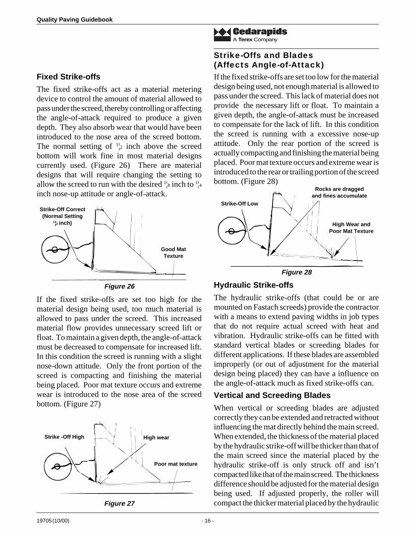
Fixed Strike-offs
The fixed strike-offs act as a material meteringdevice to control the amount of material allowed topass under the screed, thereby controlling or affectingthe angle-of-attack required to produce a givendepth. They also absorb wear that would have beenintroduced to the nose area of the screed bottom.The normal setting of 1¦2 inch above the screedbottom will work fine in most material designscurrently used. (Figure 26) There are materialdesigns that will require changing the setting toallow the screed to run with the desired 1¦8 inch to 1¦4inch nose-up attitude or angle-of-attack.
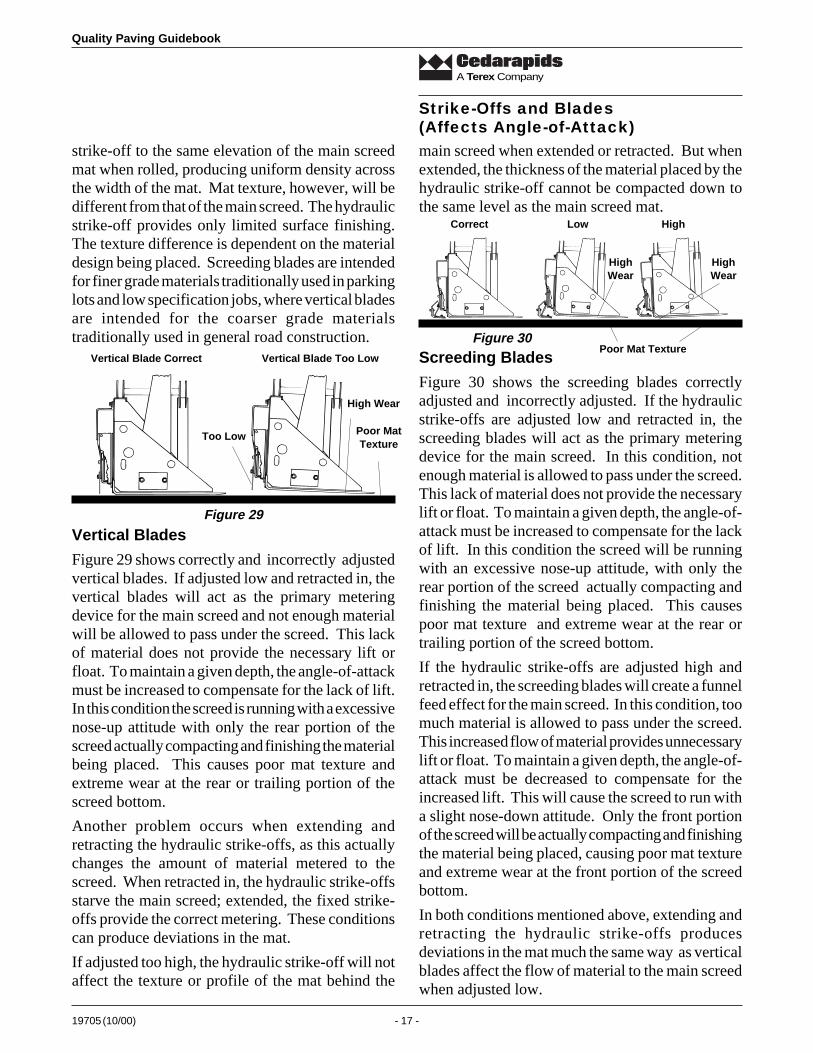
If the fixed strike-offs are set too low for the materialdesign being used, not enough material is allowed topass under the screed. This lack of material does notprovide the necessary lift or float. To maintain agiven depth, the angle-of-attack must be increasedto compensate for the lack of lift. In this conditionthe screed is running with a excessive nose-upattitude. Only the rear portion of the screed isactually compacting and finishing the material beingplaced. Poor mat texture occurs and extreme wear isintroduced to the rear or trailing portion of the screedbottom. (Figure 28)
Strike-Offs and Blades(Affects Angle-of-Attack)
Strike -Off High High wear
Poor mat texture
If the fixed strike-offs are set too high for thematerial design being used, too much material isallowed to pass under the screed. This increasedmaterial flow provides unnecessary screed lift orfloat. To maintain a given depth, the angle-of-attackmust be decreased to compensate for increased lift.In this condition the screed is running with a slightnose-down attitude. Only the front portion of thescreed is compacting and finishing the materialbeing placed. Poor mat texture occurs and extremewear is introduced to the nose area of the screedbottom. (Figure 27)
Strike-Off Correct(Normal Setting
1¦2 inch)
Good MatTexture
Hydraulic Strike-offs
The hydraulic strike-offs (that could be or aremounted on Fastach screeds) provide the contractorwith a means to extend paving widths in job typesthat do not require actual screed with heat andvibration. Hydraulic strike-offs can be fitted withstandard vertical blades or screeding blades fordifferent applications. If these blades are assembledimproperly (or out of adjustment for the materialdesign being placed) they can have a influence onthe angle-of-attack much as fixed strike-offs can.
Vertical and Screeding Blades
When vertical or screeding blades are adjustedcorrectly they can be extended and retracted withoutinfluencing the mat directly behind the main screed.When extended, the thickness of the material placedby the hydraulic strike-off will be thicker than that ofthe main screed since the material placed by thehydraulic strike-off is only struck off and isn’tcompacted like that of the main screed. The thicknessdifference should be adjusted for the material designbeing used. If adjusted properly, the roller willcompact the thicker material placed by the hydraulic
Figure 26
Figure 27
Strike-Off Low
High Wear andPoor Mat Texture
Rocks are draggedand fines accumulate
Figure 28
19705 (10/00) - 17 -
Quality Paving Guidebook
A Terex Company
strike-off to the same elevation of the main screedmat when rolled, producing uniform density acrossthe width of the mat. Mat texture, however, will bedifferent from that of the main screed. The hydraulicstrike-off provides only limited surface finishing.The texture difference is dependent on the materialdesign being placed. Screeding blades are intendedfor finer grade materials traditionally used in parkinglots and low specification jobs, where vertical bladesare intended for the coarser grade materialstraditionally used in general road construction.
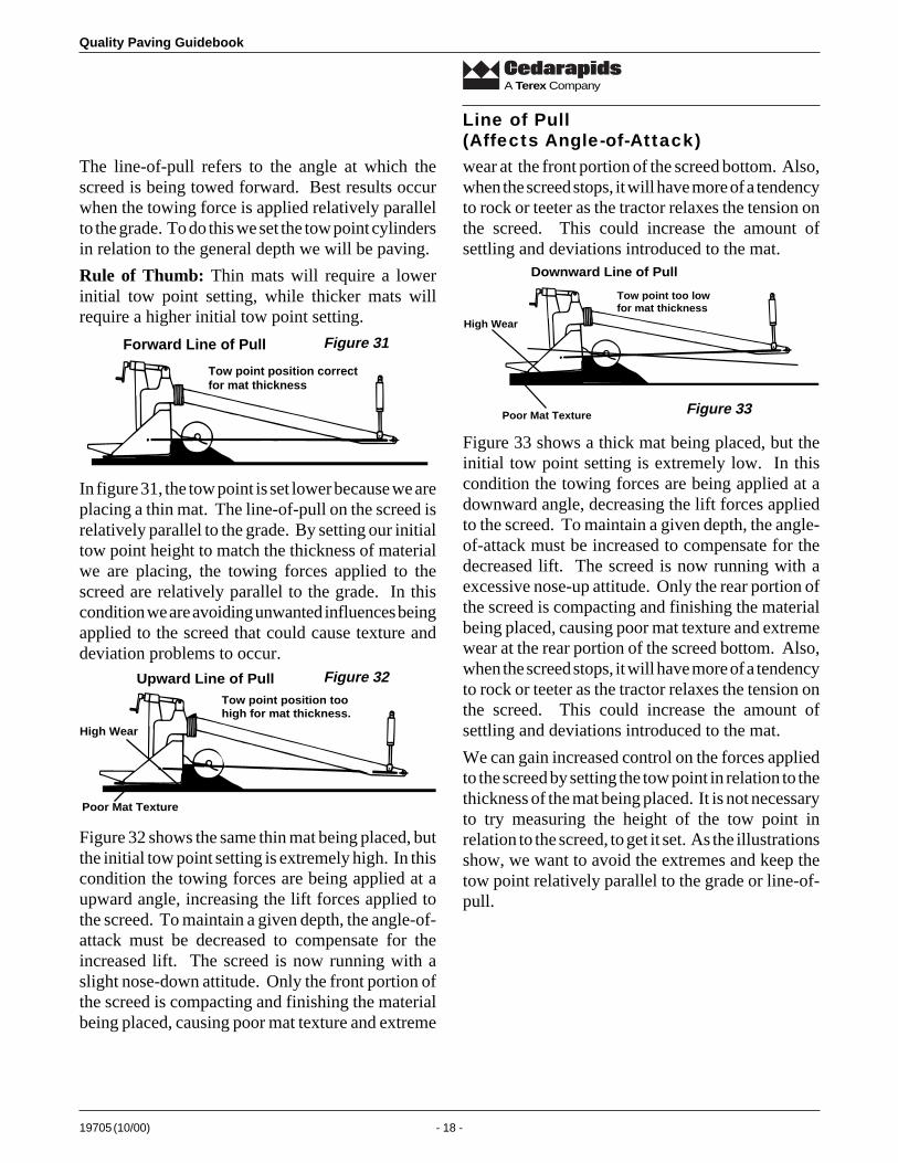
Vertical Blades
Figure 29 shows correctly and incorrectly adjustedvertical blades. If adjusted low and retracted in, thevertical blades will act as the primary meteringdevice for the main screed and not enough materialwill be allowed to pass under the screed. This lackof material does not provide the necessary lift orfloat. To maintain a given depth, the angle-of-attackmust be increased to compensate for the lack of lift.In this condition the screed is running with a excessivenose-up attitude with only the rear portion of thescreed actually compacting and finishing the materialbeing placed. This causes poor mat texture andextreme wear at the rear or trailing portion of thescreed bottom.
Another problem occurs when extending andretracting the hydraulic strike-offs, as this actuallychanges the amount of material metered to thescreed. When retracted in, the hydraulic strike-offsstarve the main screed; extended, the fixed strike-offs provide the correct metering. These conditionscan produce deviations in the mat.
If adjusted too high, the hydraulic strike-off will notaffect the texture or profile of the mat behind the
main screed when extended or retracted. But whenextended, the thickness of the material placed by thehydraulic strike-off cannot be compacted down tothe same level as the main screed mat.
Strike-Offs and Blades(Affects Angle-of-Attack)
Correct Low
HighWear
High
HighWear
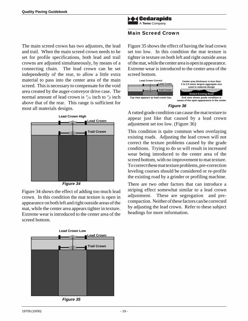
Poor Mat TextureScreeding Blades
Figure 30 shows the screeding blades correctlyadjusted and incorrectly adjusted. If the hydraulicstrike-offs are adjusted low and retracted in, thescreeding blades will act as the primary meteringdevice for the main screed. In this condition, notenough material is allowed to pass under the screed.This lack of material does not provide the necessarylift or float. To maintain a given depth, the angle-of-attack must be increased to compensate for the lackof lift. In this condition the screed will be runningwith an excessive nose-up attitude, with only therear portion of the screed actually compacting andfinishing the material being placed. This causespoor mat texture and extreme wear at the rear ortrailing portion of the screed bottom.
If the hydraulic strike-offs are adjusted high andretracted in, the screeding blades will create a funnelfeed effect for the main screed. In this condition, toomuch material is allowed to pass under the screed.This increased flow of material provides unnecessarylift or float. To maintain a given depth, the angle-of-attack must be decreased to compensate for theincreased lift. This will cause the screed to run witha slight nose-down attitude. Only the front portionof the screed will be actually compacting and finishingthe material being placed, causing poor mat textureand extreme wear at the front portion of the screedbottom.
In both conditions mentioned above, extending andretracting the hydraulic strike-offs producesdeviations in the mat much the same way as verticalblades affect the flow of material to the main screedwhen adjusted low.
Vertical Blade Correct Vertical Blade Too Low
Too Low
High Wear
Poor MatTexture
Figure 29
Figure 30
Quality Paving Guidebook
19705 (10/00) - 18 -
A Terex Company
wear at the front portion of the screed bottom. Also,when the screed stops, it will have more of a tendencyto rock or teeter as the tractor relaxes the tension onthe screed. This could increase the amount ofsettling and deviations introduced to the mat.
The line-of-pull refers to the angle at which thescreed is being towed forward. Best results occurwhen the towing force is applied relatively parallelto the grade. To do this we set the tow point cylindersin relation to the general depth we will be paving.
Rule of Thumb: Thin mats will require a lowerinitial tow point setting, while thicker mats willrequire a higher initial tow point setting.
Line of Pull(Affects Angle-of-Attack)
Forward Line of Pull
Tow point position correctfor mat thickness
In figure 31, the tow point is set lower because we areplacing a thin mat. The line-of-pull on the screed isrelatively parallel to the grade. By setting our initialtow point height to match the thickness of materialwe are placing, the towing forces applied to thescreed are relatively parallel to the grade. In thiscondition we are avoiding unwanted influences beingapplied to the screed that could cause texture anddeviation problems to occur.
Upward Line of PullTow point position toohigh for mat thickness.
High Wear
Poor Mat Texture
Figure 32 shows the same thin mat being placed, butthe initial tow point setting is extremely high. In thiscondition the towing forces are being applied at aupward angle, increasing the lift forces applied tothe screed. To maintain a given depth, the angle-of-attack must be decreased to compensate for theincreased lift. The screed is now running with aslight nose-down attitude. Only the front portion ofthe screed is compacting and finishing the materialbeing placed, causing poor mat texture and extreme
Downward Line of Pull
Tow point too lowfor mat thickness
Poor Mat Texture
High Wear
Figure 33 shows a thick mat being placed, but theinitial tow point setting is extremely low. In thiscondition the towing forces are being applied at adownward angle, decreasing the lift forces appliedto the screed. To maintain a given depth, the angle-of-attack must be increased to compensate for thedecreased lift. The screed is now running with aexcessive nose-up attitude. Only the rear portion ofthe screed is compacting and finishing the materialbeing placed, causing poor mat texture and extremewear at the rear portion of the screed bottom. Also,when the screed stops, it will have more of a tendencyto rock or teeter as the tractor relaxes the tension onthe screed. This could increase the amount ofsettling and deviations introduced to the mat.
We can gain increased control on the forces appliedto the screed by setting the tow point in relation to thethickness of the mat being placed. It is not necessaryto try measuring the height of the tow point inrelation to the screed, to get it set. As the illustrationsshow, we want to avoid the extremes and keep thetow point relatively parallel to the grade or line-of-pull.
Figure 31
Figure 32
Figure 33
19705 (10/00) - 19 -
Quality Paving Guidebook
A Terex Company
The main screed crown has two adjustors, the leadand trail. When the main screed crown needs to beset for profile specifications, both lead and trailcrowns are adjusted simultaneously, by means of aconnecting chain. The lead crown can be setindependently of the rear, to allow a little extramaterial to pass into the center area of the mainscreed. This is necessary to compensate for the voidarea created by the auger-conveyor drive case. Thenormal amount of lead crown is 1¦16 inch to 1¦8 inchabove that of the rear. This range is sufficient formost all materials designs.
Main Screed Crown
Lead Crown HighLead Crown
Trail Crown
Lead Crown LowLead Crown
Trail Crown
Figure 34 shows the effect of adding too much leadcrown. In this condition the mat texture is open inappearance on both left and right outside areas of themat, while the center area appears tighter in texture.Extreme wear is introduced to the center area of thescreed bottom.
Figure 35 shows the effect of having the lead crownset too low. In this condition the mat texture istighter in texture on both left and right outside areasof the mat, while the center area is open in appearance.Extreme wear is introduced to the center area of thescreed bottom.
A rutted grade condition can cause the mat texture toappear just like that caused by a lead crownadjustment set too low. (Figure 36)
This condition is quite common when overlayingexisting roads. Adjusting the lead crown will notcorrect the texture problems caused by the gradeconditions. Trying to do so will result in increasedwear being introduced to the center area of thescreed bottom, with no improvement to mat texture.To correct these mat texture problems, pre-correctionleveling courses should be considered or re-profilethe existing road by a grinder or profiling machine.
There are two other factors that can introduce astriping effect somewhat similar to a lead crownadjustment. These are segregation and pre-compaction. Neither of these factors can be correctedby adjusting the lead crown. Refer to these subjectheadings for more information.
Figure 34
Figure 35
Lead Crown CorrectLead Crown
Trail Crown
Top view appears as lead crown low. End view shows grade condition iscause of the open appearance in the center
Center area thickness is less than2 to 2.5 times largest aggregate size
used in material design
Rutted Existing Road
Figure 36
Quality Paving Guidebook
19705 (10/00) - 20 -
A Terex Company
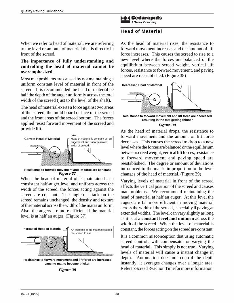
When we refer to head of material, we are referringto the level or amount of material that is directly infront of the screed.
The importance of fully understanding andcontrolling the head of material cannot beoveremphasized.
Most mat problems are caused by not maintaining auniform constant level of material in front of thescreed. It is recommended the head of material behalf the depth of the auger uniformly across the totalwidth of the screed (just to the level of the shaft).
The head of material exerts a force against two areasof the screed, the mold board or face of the screedand the front areas of the screed bottom. The forcesapplied resist forward movement of the screed andprovide lift.
Correct Head of Material
Resistance to forward movement and lift force are constant
Head of material is constant at halfauger level and uniform acrosswidth of screed.
When the head of material of is maintained at aconsistent half-auger level and uniform across thewidth of the screed, the forces acting against thescreed are constant. The angle-of-attack on thescreed remains unchanged, the density and textureof the material across the width of the mat is uniform.Also, the augers are more efficient if the materiallevel is at half an auger. (Figure 37)
Increased Head of Material
Resistance to forward movement and lift force are increasedcausing mat to become thicker.
An increase in the material causedthe screed to rise.
As the head of material rises, the resistance toforward movement increases and the amount of liftforce increases. This causes the screed to rise to anew level where the forces are balanced or theequilibrium between screed weight, vertical liftforces, resistance to forward movement, and pavingspeed are reestablished. (Figure 38)
Decreased Head of Material
Resistance to forward movement and lift force are decreasedresulting in the mat getting thinner
Head of Material
Figure 37
Figure 38
Figure 39
As the head of material drops, the resistance toforward movement and the amount of lift forcedecreases. This causes the screed to drop to a newlevel where the forces are balanced or the equilibriumbetween screed weight, vertical lift forces, resistanceto forward movement and paving speed arereestablished. The degree or amount of deviationsintroduced to the mat is in proportion to the levelchanges of the head of material. (Figure 39)
Varying levels of material in front of the screedaffects the vertical position of the screed and causesmat problems. We recommend maintaining thehead of material at half an auger. At this level theaugers are far more efficient in moving materialacross the width of the screed, especially if paving atextended widths. The level can vary slightly as longas it is at a constant level and uniform across thewidth of the screed. When the level of material isconstant, the forces acting on the screed are constant.
It is a common misconception that using automaticscreed controls will compensate for varying thehead of material. This simply is not true. Varyinglevels of material will cause a instant change indepth. Automation does not control the depthinstantly; it averages changes over a longer area.Refer to Screed Reaction Time for more information.
19705 (10/00) - 21 -
Quality Paving Guidebook
A Terex Company
Controlling Head of Material
Two systems (the flow gates, and the material feedsensors) are independently adjusted but work inconjunction with each other to control the head ofmaterial. The flow gates control the level of materialin the center area of the auger chamber. The feedsensors control the level of material at the outboardends of the augers. When set properly to match thepaving speed and the width and depth of the matbeing placed, a constant, uniform head of materialcan be maintained.
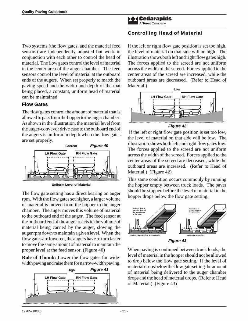
Flow Gates
The flow gates control the amount of material that isallowed to pass from the hopper to the auger chamber.As shown in the illustration, the material level fromthe auger-conveyor drive case to the outboard end ofthe augers is uniform in depth when the flow gatesare set properly.
If the left or right flow gate position is set too high,the level of material on that side will be high. Theillustration shows both left and right flow gates high.The forces applied to the screed are not uniformacross the width of the screed. Forces applied to thecenter areas of the screed are increased, while theoutboard areas are decreased. (Refer to Head ofMaterial.)
High
LH Flow Gate RH Flow Gate
If the left or right flow gate position is set too low,the level of material on that side will be low. Theillustration shows both left and right flow gates low.The forces applied to the screed are not uniformacross the width of the screed. Forces applied to thecenter areas of the screed are decreased, while theoutboard areas are increased. (Refer to Head ofMaterial.) (Figure 42)
This same condition occurs commonly by runningthe hopper empty between truck loads. The pavershould be stopped before the level of material in thehopper drops below the flow gate setting.
Uniform flow ofmaterial throughthe tunnel areato the auger
Uniform Material Flow Across Auger
Material level intunnel drops belowflow gate setting
Material Flow Inconsistant
The flow gate setting has a direct bearing on augerrpm. With the flow gates set higher, a larger volumeof material is moved from the hopper to the augerchamber. The auger moves this volume of materialto the outboard end of the auger. The feed sensor atthe outboard end of the auger reacts to the volume ofmaterial being carried by the auger, slowing theauger rpm down to maintain a given level. When theflow gates are lowered, the augers have to turn fasterto move the same amount of material to maintain theproper level at the feed sensor. (Figure 40)
Rule of Thumb: Lower the flow gates for wide-width paving and raise them for narrow-width paving.
Correct
Uniform Level of Material
LH Flow Gate RH Flow Gate
Figure 40
Figure 41
When paving is continued between truck loads, thelevel of material in the hopper should not be allowedto drop below the flow gate setting. If the level ofmaterial drops below the flow gate setting the amountof material being delivered to the auger chamberdrops and the head of material drops. (Refer to Headof Material.) (Figure 43)
Figure 43
Low
LH Flow Gate RH Flow Gate
Figure 42
Quality Paving Guidebook
19705 (10/00) - 22 -
A Terex Company
Even small changes in the amount of material beingdelivered to the auger chamber can have an effect onthe consistency of the mat produced. (Figure 44)
Spilled Material
Material dropped in front of a paver by trucks ordamaged hopper flashing is very common. This isalso a prime source of mat-related problems. Thematerial that is deposited in front of a paver adds tothe volume of material in the auger chamber as thepaver passes over it. This increased volume increasesthe head of material in front of the screed. (Figure45)
If the material deposited is raked or shoveled outover a wide area in an attempt to prevent overloadingor changing the head of material, a second problemis created. The material that was spread out coolsconsiderably and adds to the elevation of the roadsurface. When the paver passes over this area the
Material dropped in front of paver causes:1. Overfeeding of the screed (head of material)2. Increases elevation of grade (mat texture problems)3. Creates more grade irregularities
mat thickness in these areas is thinner. This couldcause mat texture problems related to paving depthversus aggregate size. This also creates moredeviations in the grade that we have to pave over. Ifmaterial is dropped in front of the paver, it should beremoved to prevent adversely affecting the operation.
(Refer to Material Designs for more information.)
Material Feed Sensors
The feed sensors control the level of material at theoutboard end of the augers and work in conjunctionwith the flow gate settings to maintain a constant,uniform head of material. Cedarapids uses threetypes of feed sensors: the limit switch type, theproportional sensor and sonic feeder controls. Theposition of the feed sensor should always be locatedat the outboard end of the last auger or off the endgate, if variable width paving is done. (Figures 47-49)
Limit Switch
The limit switch feeder controls are the on-off type.When the material level rises to a set point, theauger-conveyor system for that side is shut off.
When the material level drops below a set point, theauger-conveyor is turned on. (Figure 46)
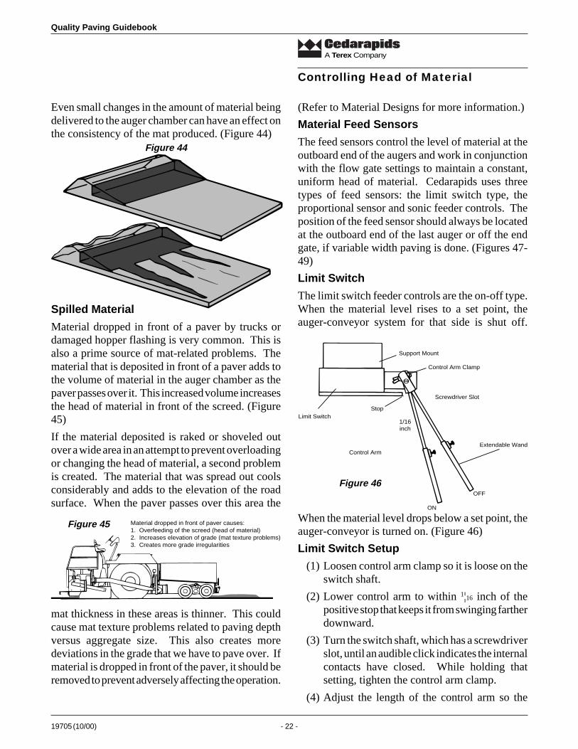
Limit Switch Setup
(1) Loosen control arm clamp so it is loose on theswitch shaft.
(2) Lower control arm to within 1¦16 inch of thepositive stop that keeps it from swinging fartherdownward.
(3) Turn the switch shaft, which has a screwdriverslot, until an audible click indicates the internalcontacts have closed. While holding thatsetting, tighten the control arm clamp.
(4) Adjust the length of the control arm so the
Controlling Head of Material
Figure 44
Figure 45
Control ArmExtendable Wand
ON
OFF
Screwdriver Slot
Control Arm Clamp
Stop
Support Mount
Limit Switch1/16inch
Figure 46
19705 (10/00) - 23 -
Quality Paving Guidebook
A Terex Company
Controlling Head of Material
5) Advance the travel control lever forward.
6) Set auger conveyor switch to auto.
WARNING!All personnel should be prepared for the paver tocreep forward.
7) Loosen control arm clamp so the arm is free torotate on the sensor shaft.
8) Position control arm at 45°. See illustration forboth left and right sensor control armpositioning.
9) While holding control arm in position, rotatesensor shaft with a screwdriver until the augerjust stops.
10) Tighten the control arm clamp.
Generation III Sonic Feed Control
Upgrading from standard proportional systems toDemand Based Ultrasonics does not require changingor rewiring existing tractor systems. Simply mountthe control units on each side of the screed and plugtheir cables into the receptacles the proportionalsystems used.
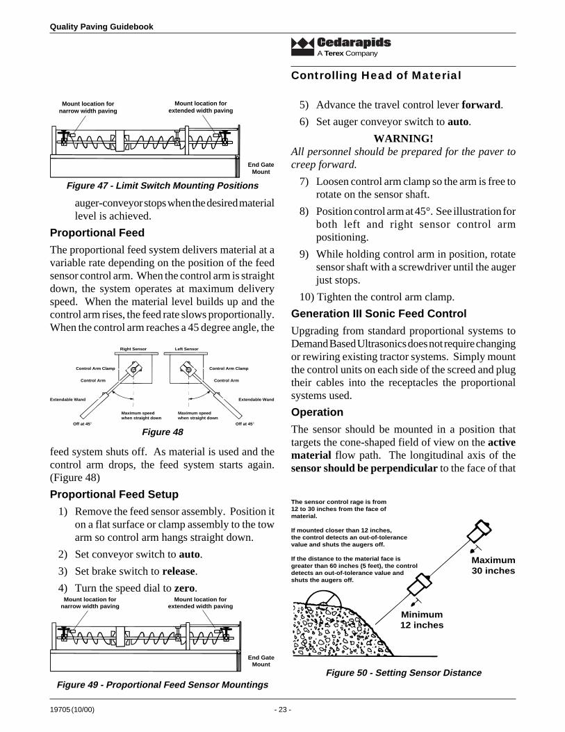
Operation
The sensor should be mounted in a position thattargets the cone-shaped field of view on the activematerial flow path. The longitudinal axis of thesensor should be perpendicular to the face of that
Mount location fornarrow width paving
Mount location forextended width paving
End GateMount
Minimum12 inches
Maximum30 inches
The sensor control rage is from12 to 30 inches from the face ofmaterial.
If mounted closer than 12 inches,the control detects an out-of-tolerancevalue and shuts the augers off.
If the distance to the material face isgreater than 60 inches (5 feet), the controldetects an out-of-tolerance value andshuts the augers off.
Figure 50 - Setting Sensor Distance
feed system shuts off. As material is used and thecontrol arm drops, the feed system starts again.(Figure 48)
Proportional Feed Setup
1) Remove the feed sensor assembly. Position iton a flat surface or clamp assembly to the towarm so control arm hangs straight down.
2) Set conveyor switch to auto.
3) Set brake switch to release.
4) Turn the speed dial to zero.
Maximum speedwhen straight down
Maximum speedwhen straight down
Off at 45°Off at 45°
Right Sensor Left Sensor
Control Arm Clamp
Control Arm
Extendable Wand
Control Arm Clamp
Control Arm
Extendable Wand
auger-conveyor stops when the desired materiallevel is achieved.
Proportional Feed
The proportional feed system delivers material at avariable rate depending on the position of the feedsensor control arm. When the control arm is straightdown, the system operates at maximum deliveryspeed. When the material level builds up and thecontrol arm rises, the feed rate slows proportionally.When the control arm reaches a 45 degree angle, the
Figure 47 - Limit Switch Mounting Positions
Figure 48
Mount location fornarrow width paving
Mount location forextended width paving
End GateMount
Figure 49 - Proportional Feed Sensor Mountings
Quality Paving Guidebook
19705 (10/00) - 24 -
A Terex Company
IncorrectSensor too high
Correct
90°
IncorrectSensor too low
Figure 51 - Setting Alignment of Sensor with Head of Material
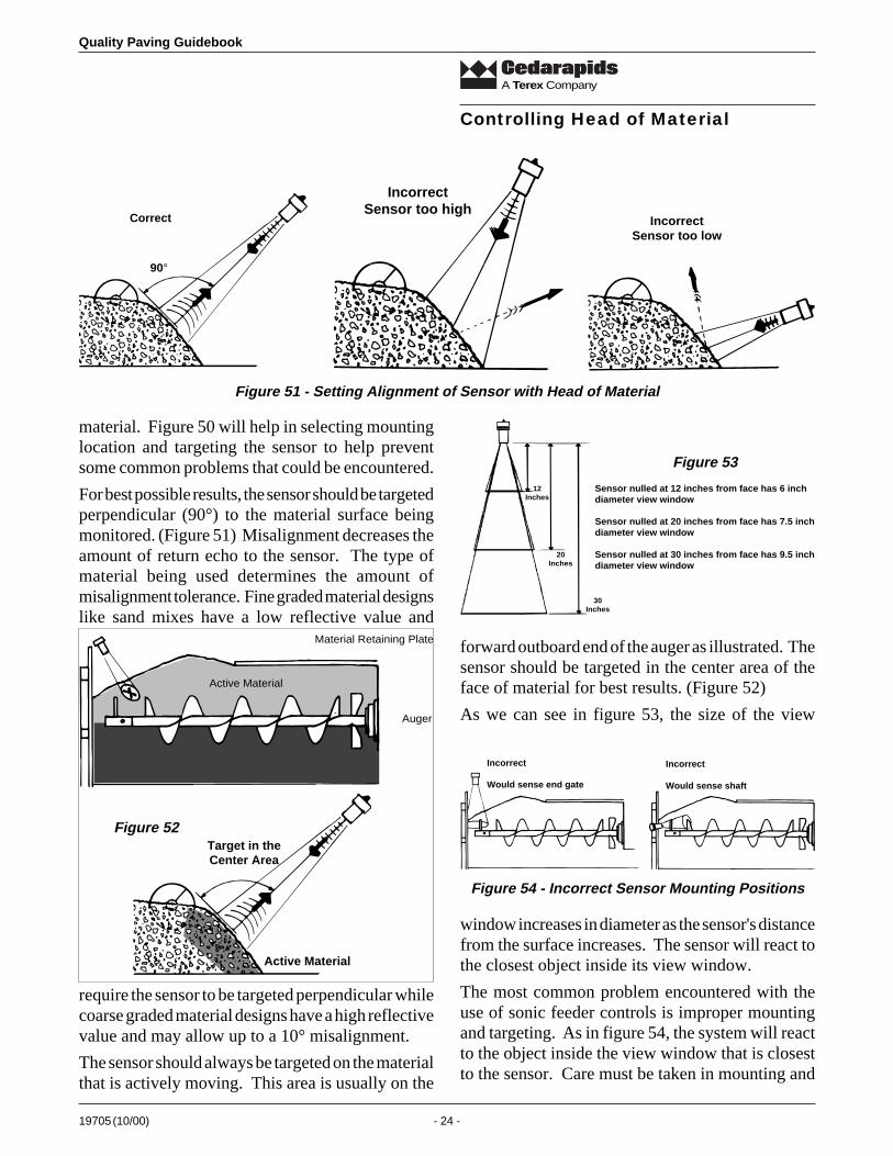
material. Figure 50 will help in selecting mountinglocation and targeting the sensor to help preventsome common problems that could be encountered.
For best possible results, the sensor should be targetedperpendicular (90°) to the material surface beingmonitored. (Figure 51) Misalignment decreases theamount of return echo to the sensor. The type ofmaterial being used determines the amount ofmisalignment tolerance. Fine graded material designslike sand mixes have a low reflective value and
Auger
Material Retaining Plate
Active Material
Controlling Head of Material
Active Material
Target in theCenter Area
require the sensor to be targeted perpendicular whilecoarse graded material designs have a high reflectivevalue and may allow up to a 10° misalignment.
The sensor should always be targeted on the materialthat is actively moving. This area is usually on the
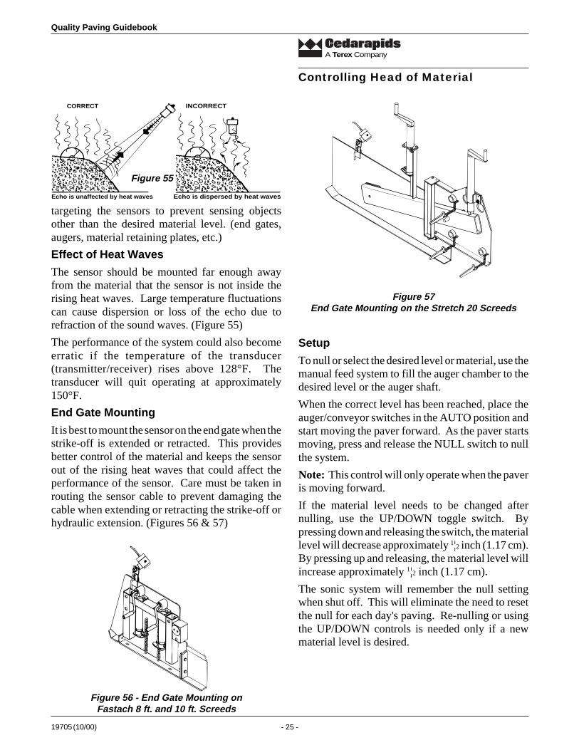
12Inches
20Inches
30Inches
Sensor nulled at 12 inches from face has 6 inchdiameter view window
Sensor nulled at 20 inches from face has 7.5 inchdiameter view window
Sensor nulled at 30 inches from face has 9.5 inchdiameter view window
Incorrect
Would sense end gate
Incorrect
Would sense shaft
forward outboard end of the auger as illustrated. Thesensor should be targeted in the center area of theface of material for best results. (Figure 52)
As we can see in figure 53, the size of the view
window increases in diameter as the sensor's distancefrom the surface increases. The sensor will react tothe closest object inside its view window.
The most common problem encountered with theuse of sonic feeder controls is improper mountingand targeting. As in figure 54, the system will reactto the object inside the view window that is closestto the sensor. Care must be taken in mounting and
Figure 53
Figure 54 - Incorrect Sensor Mounting Positions
Figure 52
19705 (10/00) - 25 -
Quality Paving Guidebook
A Terex Company
targeting the sensors to prevent sensing objectsother than the desired material level. (end gates,augers, material retaining plates, etc.)
Effect of Heat Waves
The sensor should be mounted far enough awayfrom the material that the sensor is not inside therising heat waves. Large temperature fluctuationscan cause dispersion or loss of the echo due torefraction of the sound waves. (Figure 55)
The performance of the system could also becomeerratic if the temperature of the transducer(transmitter/receiver) rises above 128°F. Thetransducer will quit operating at approximately150°F.
End Gate Mounting
It is best to mount the sensor on the end gate when thestrike-off is extended or retracted. This providesbetter control of the material and keeps the sensorout of the rising heat waves that could affect theperformance of the sensor. Care must be taken inrouting the sensor cable to prevent damaging thecable when extending or retracting the strike-off orhydraulic extension. (Figures 56 & 57)
Controlling Head of Material
CORRECT
Echo is unaffected by heat waves
INCORRECT
Echo is dispersed by heat waves
Figure 55
Figure 56 - End Gate Mounting onFastach 8 ft. and 10 ft. Screeds
Figure 57End Gate Mounting on the Stretch 20 Screeds
Setup
To null or select the desired level or material, use themanual feed system to fill the auger chamber to thedesired level or the auger shaft.
When the correct level has been reached, place theauger/conveyor switches in the AUTO position andstart moving the paver forward. As the paver startsmoving, press and release the NULL switch to nullthe system.
Note: This control will only operate when the paveris moving forward.
If the material level needs to be changed afternulling, use the UP/DOWN toggle switch. Bypressing down and releasing the switch, the materiallevel will decrease approximately 1¦2 inch (1.17 cm).By pressing up and releasing, the material level willincrease approximately 1¦2 inch (1.17 cm).
The sonic system will remember the null settingwhen shut off. This will eliminate the need to resetthe null for each day's paving. Re-nulling or usingthe UP/DOWN controls is needed only if a newmaterial level is desired.
Quality Paving Guidebook
19705 (10/00) - 26 -
A Terex Company
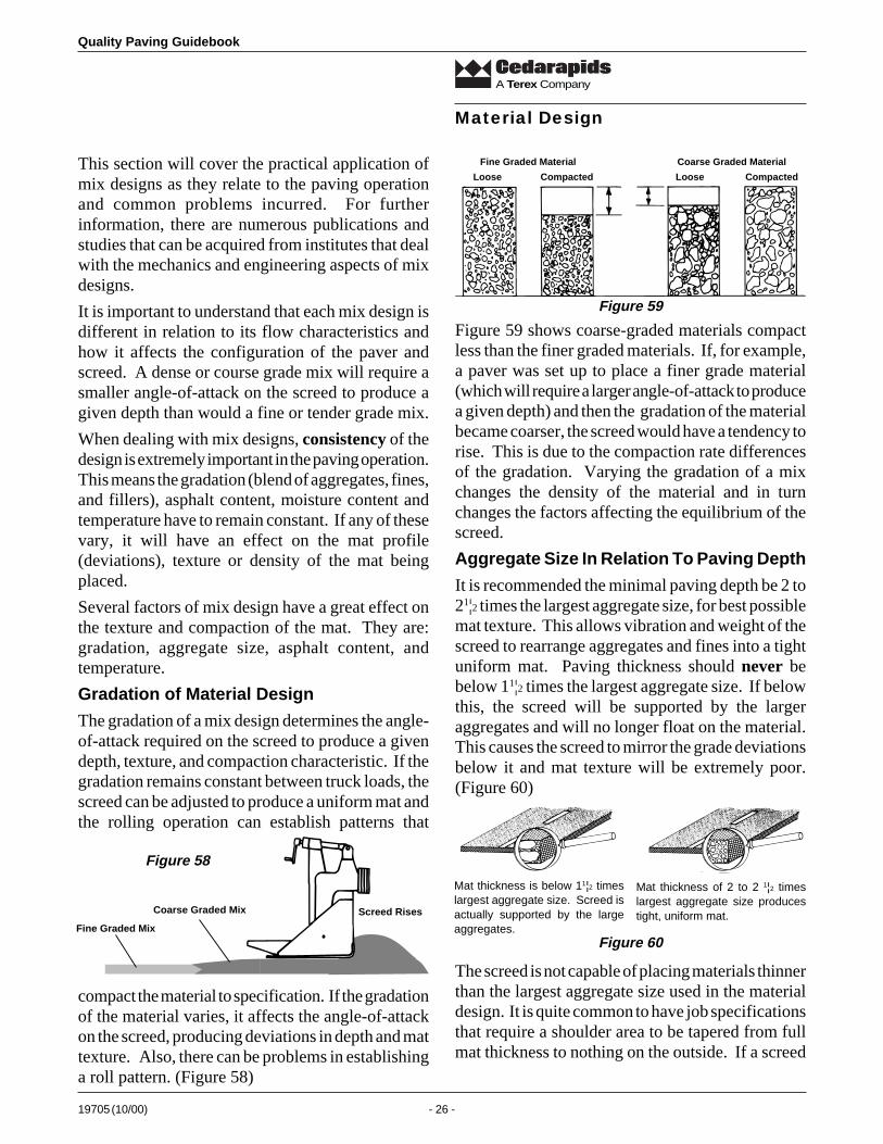
This section will cover the practical application ofmix designs as they relate to the paving operationand common problems incurred. For furtherinformation, there are numerous publications andstudies that can be acquired from institutes that dealwith the mechanics and engineering aspects of mixdesigns.
It is important to understand that each mix design isdifferent in relation to its flow characteristics andhow it affects the configuration of the paver andscreed. A dense or course grade mix will require asmaller angle-of-attack on the screed to produce agiven depth than would a fine or tender grade mix.
When dealing with mix designs, consistency of thedesign is extremely important in the paving operation.This means the gradation (blend of aggregates, fines,and fillers), asphalt content, moisture content andtemperature have to remain constant. If any of thesevary, it will have an effect on the mat profile(deviations), texture or density of the mat beingplaced.
Several factors of mix design have a great effect onthe texture and compaction of the mat. They are:gradation, aggregate size, asphalt content, andtemperature.
Gradation of Material Design
The gradation of a mix design determines the angle-of-attack required on the screed to produce a givendepth, texture, and compaction characteristic. If thegradation remains constant between truck loads, thescreed can be adjusted to produce a uniform mat andthe rolling operation can establish patterns that
Material Design
compact the material to specification. If the gradationof the material varies, it affects the angle-of-attackon the screed, producing deviations in depth and mattexture. Also, there can be problems in establishinga roll pattern. (Figure 58)
Screed RisesCoarse Graded Mix
Fine Graded Mix
Loose Compacted Loose Compacted
Fine Graded Material Coarse Graded Material
Figure 59 shows coarse-graded materials compactless than the finer graded materials. If, for example,a paver was set up to place a finer grade material(which will require a larger angle-of-attack to producea given depth) and then the gradation of the materialbecame coarser, the screed would have a tendency torise. This is due to the compaction rate differencesof the gradation. Varying the gradation of a mixchanges the density of the material and in turnchanges the factors affecting the equilibrium of thescreed.
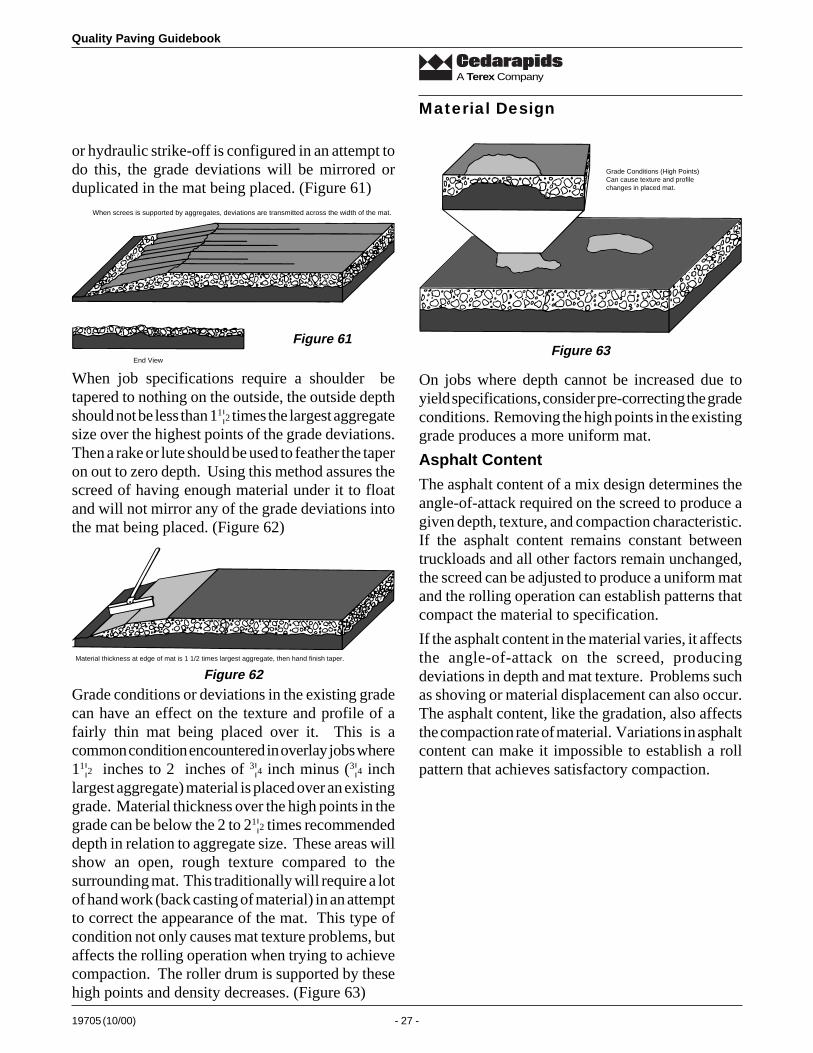
Aggregate Size In Relation To Paving Depth
It is recommended the minimal paving depth be 2 to21¦2 times the largest aggregate size, for best possiblemat texture. This allows vibration and weight of thescreed to rearrange aggregates and fines into a tightuniform mat. Paving thickness should never bebelow 11¦2 times the largest aggregate size. If belowthis, the screed will be supported by the largeraggregates and will no longer float on the material.This causes the screed to mirror the grade deviationsbelow it and mat texture will be extremely poor.(Figure 60)
Figure 58
Mat thickness is below 11¦2 timeslargest aggregate size. Screed isactually supported by the largeaggregates.
Mat thickness of 2 to 2 1¦2 timeslargest aggregate size producestight, uniform mat.
The screed is not capable of placing materials thinnerthan the largest aggregate size used in the materialdesign. It is quite common to have job specificationsthat require a shoulder area to be tapered from fullmat thickness to nothing on the outside. If a screed
Figure 60
Figure 59
19705 (10/00) - 27 -
Quality Paving Guidebook
A Terex Company
or hydraulic strike-off is configured in an attempt todo this, the grade deviations will be mirrored orduplicated in the mat being placed. (Figure 61)
Material Design
When screes is supported by aggregates, deviations are transmitted across the width of the mat.
End View
Figure 61
When job specifications require a shoulder betapered to nothing on the outside, the outside depthshould not be less than 11¦2 times the largest aggregatesize over the highest points of the grade deviations.Then a rake or lute should be used to feather the taperon out to zero depth. Using this method assures thescreed of having enough material under it to floatand will not mirror any of the grade deviations intothe mat being placed. (Figure 62)
Figure 62
Grade conditions or deviations in the existing gradecan have an effect on the texture and profile of afairly thin mat being placed over it. This is acommon condition encountered in overlay jobs where11¦2 inches to 2 inches of 3¦4 inch minus (3¦4 inchlargest aggregate) material is placed over an existinggrade. Material thickness over the high points in thegrade can be below the 2 to 21¦2 times recommendeddepth in relation to aggregate size. These areas willshow an open, rough texture compared to thesurrounding mat. This traditionally will require a lotof hand work (back casting of material) in an attemptto correct the appearance of the mat. This type ofcondition not only causes mat texture problems, butaffects the rolling operation when trying to achievecompaction. The roller drum is supported by thesehigh points and density decreases. (Figure 63)
Grade Conditions (High Points)Can cause texture and profilechanges in placed mat.
Figure 63
On jobs where depth cannot be increased due toyield specifications, consider pre-correcting the gradeconditions. Removing the high points in the existinggrade produces a more uniform mat.
Asphalt Content
The asphalt content of a mix design determines theangle-of-attack required on the screed to produce agiven depth, texture, and compaction characteristic.If the asphalt content remains constant betweentruckloads and all other factors remain unchanged,the screed can be adjusted to produce a uniform matand the rolling operation can establish patterns thatcompact the material to specification.
If the asphalt content in the material varies, it affectsthe angle-of-attack on the screed, producingdeviations in depth and mat texture. Problems suchas shoving or material displacement can also occur.The asphalt content, like the gradation, also affectsthe compaction rate of material. Variations in asphaltcontent can make it impossible to establish a rollpattern that achieves satisfactory compaction.
Material thickness at edge of mat is 1 1/2 times largest aggregate, then hand finish taper.
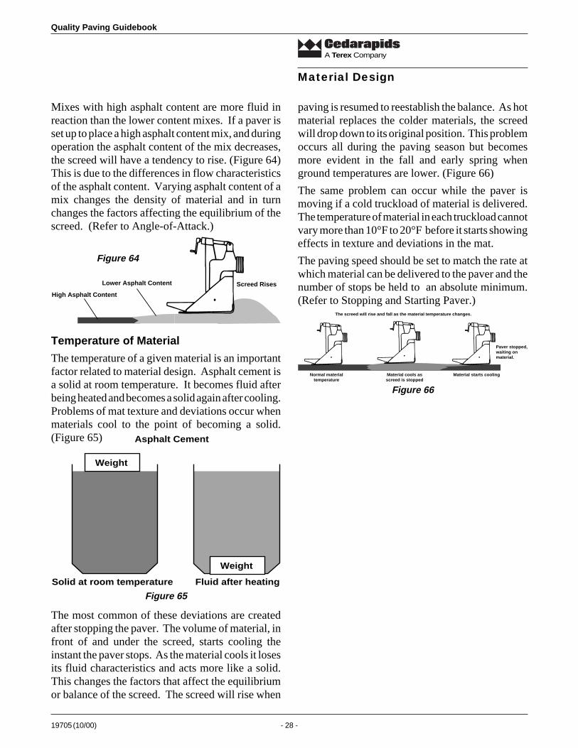
Quality Paving Guidebook
19705 (10/00) - 28 -
A Terex Company
Mixes with high asphalt content are more fluid inreaction than the lower content mixes. If a paver isset up to place a high asphalt content mix, and duringoperation the asphalt content of the mix decreases,the screed will have a tendency to rise. (Figure 64)This is due to the differences in flow characteristicsof the asphalt content. Varying asphalt content of amix changes the density of material and in turnchanges the factors affecting the equilibrium of thescreed. (Refer to Angle-of-Attack.)
paving is resumed to reestablish the balance. As hotmaterial replaces the colder materials, the screedwill drop down to its original position. This problemoccurs all during the paving season but becomesmore evident in the fall and early spring whenground temperatures are lower. (Figure 66)
The same problem can occur while the paver ismoving if a cold truckload of material is delivered.The temperature of material in each truckload cannotvary more than 10°F to 20°F before it starts showingeffects in texture and deviations in the mat.
The paving speed should be set to match the rate atwhich material can be delivered to the paver and thenumber of stops be held to an absolute minimum.(Refer to Stopping and Starting Paver.)
Material Design
Screed RisesLower Asphalt Content
High Asphalt Content
Temperature of Material
The temperature of a given material is an importantfactor related to material design. Asphalt cement isa solid at room temperature. It becomes fluid afterbeing heated and becomes a solid again after cooling.Problems of mat texture and deviations occur whenmaterials cool to the point of becoming a solid.(Figure 65)
Weight
Weight
Asphalt Cement
Solid at room temperature Fluid after heating
Figure 64
Figure 65
The most common of these deviations are createdafter stopping the paver. The volume of material, infront of and under the screed, starts cooling theinstant the paver stops. As the material cools it losesits fluid characteristics and acts more like a solid.This changes the factors that affect the equilibriumor balance of the screed. The screed will rise when
Normal materialtemperature
Material cools asscreed is stopped
Material starts cooling
Paver stopped,waiting onmaterial.
The screed will rise and fall as the material temperature changes.
Figure 66
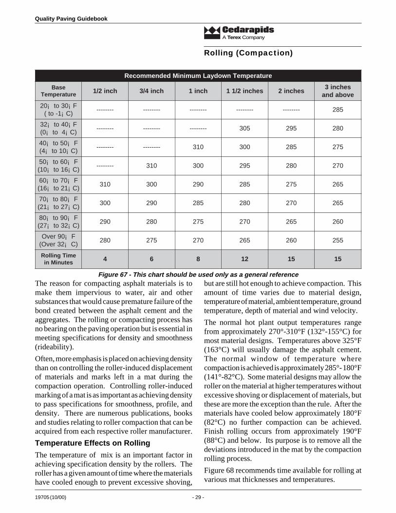
19705 (10/00) - 29 -
Quality Paving Guidebook
A Terex Company
The reason for compacting asphalt materials is tomake them impervious to water, air and othersubstances that would cause premature failure of thebond created between the asphalt cement and theaggregates. The rolling or compacting process hasno bearing on the paving operation but is essential inmeeting specifications for density and smoothness(rideability).
Often, more emphasis is placed on achieving densitythan on controlling the roller-induced displacementof materials and marks left in a mat during thecompaction operation. Controlling roller-inducedmarking of a mat is as important as achieving densityto pass specifications for smoothness, profile, anddensity. There are numerous publications, booksand studies relating to roller compaction that can beacquired from each respective roller manufacturer.
Temperature Effects on Rolling
The temperature of mix is an important factor inachieving specification density by the rollers. Theroller has a given amount of time where the materialshave cooled enough to prevent excessive shoving,
Rolling (Compaction)
but are still hot enough to achieve compaction. Thisamount of time varies due to material design,temperature of material, ambient temperature, groundtemperature, depth of material and wind velocity.
The normal hot plant output temperatures rangefrom approximately 270°-310°F (132°-155°C) formost material designs. Temperatures above 325°F(163°C) will usually damage the asphalt cement.The normal window of temperature wherecompaction is achieved is approximately 285°- 180°F(141°-82°C). Some material designs may allow theroller on the material at higher temperatures withoutexcessive shoving or displacement of materials, butthese are more the exception than the rule. After thematerials have cooled below approximately 180°F(82°C) no further compaction can be achieved.Finish rolling occurs from approximately 190°F(88°C) and below. Its purpose is to remove all thedeviations introduced in the mat by the compactionrolling process.
Figure 68 recommends time available for rolling atvarious mat thicknesses and temperatures.
Figure 67 - This chart should be used only as a general reference
erutarepmeTnwodyaLmuminiMdednemmoceR
esaBerutarepmeT hcni2/1 hcni4/3 hcni1 sehcni2/11 sehcni2
sehcni3evobadna
F¡03ot¡02)C¡1-ot(
-------- -------- -------- -------- -------- 582
F¡04ot¡23)C¡4ot¡0(
-------- -------- -------- 503 592 082
F¡05ot¡04)C¡01ot¡4(
-------- -------- 013 003 582 572
F¡06ot¡05)C¡61ot¡01(
-------- 013 003 592 082 072
F¡07ot¡06)C¡12ot¡61(
013 003 092 582 572 562
F¡08ot¡07)C¡72ot¡12(
003 092 582 082 072 562
F¡09ot¡08)C¡23ot¡72(
092 082 572 072 562 062
F¡09revO)C¡23revO(
082 572 072 562 062 552
emiTgnilloRsetuniMni 4 6 8 21 51 51
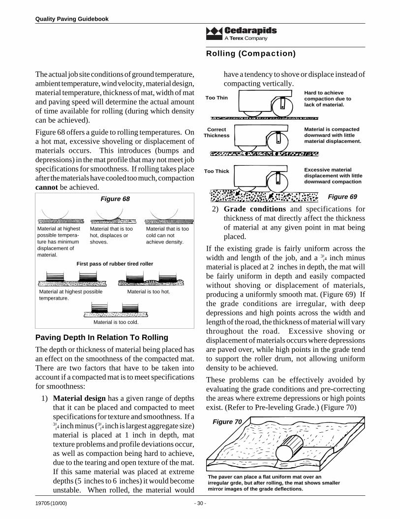
Quality Paving Guidebook
19705 (10/00) - 30 -
A Terex Company
have a tendency to shove or displace instead ofcompacting vertically.
Rolling (Compaction)
The actual job site conditions of ground temperature,ambient temperature, wind velocity, material design,material temperature, thickness of mat, width of matand paving speed will determine the actual amountof time available for rolling (during which densitycan be achieved).
Figure 68 offers a guide to rolling temperatures. Ona hot mat, excessive shoveling or displacement ofmaterials occurs. This introduces (bumps anddepressions) in the mat profile that may not meet jobspecifications for smoothness. If rolling takes placeafter the materials have cooled too much, compactioncannot be achieved.
Paving Depth In Relation To Rolling
The depth or thickness of material being placed hasan effect on the smoothness of the compacted mat.There are two factors that have to be taken intoaccount if a compacted mat is to meet specificationsfor smoothness:
1) Material design has a given range of depthsthat it can be placed and compacted to meetspecifications for texture and smoothness. If a3¦4 inch minus (3¦4 inch is largest aggregate size)material is placed at 1 inch in depth, mattexture problems and profile deviations occur,as well as compaction being hard to achieve,due to the tearing and open texture of the mat.If this same material was placed at extremedepths (5 inches to 6 inches) it would becomeunstable. When rolled, the material would
Material that is toohot, displaces orshoves.
Material that is toocold can notachieve density.
First pass of rubber tired roller
Material at highest possibletemperature.
Material is too hot.
Material is too cold.
Figure 68
Material at highestpossible tempera-ture has minimumdisplacement ofmaterial.
Too Thin
CorrectThickness
Too Thick
Hard to achievecompaction due tolack of material.
Material is compacteddownward with littlematerial displacement.
Excessive materialdisplacement with littledownward compaction
Figure 69
2) Grade conditions and specifications forthickness of mat directly affect the thicknessof material at any given point in mat beingplaced.
If the existing grade is fairly uniform across thewidth and length of the job, and a 3¦4 inch minusmaterial is placed at 2 inches in depth, the mat willbe fairly uniform in depth and easily compactedwithout shoving or displacement of materials,producing a uniformly smooth mat. (Figure 69) Ifthe grade conditions are irregular, with deepdepressions and high points across the width andlength of the road, the thickness of material will varythroughout the road. Excessive shoving ordisplacement of materials occurs where depressionsare paved over, while high points in the grade tendto support the roller drum, not allowing uniformdensity to be achieved.
These problems can be effectively avoided byevaluating the grade conditions and pre-correctingthe areas where extreme depressions or high pointsexist. (Refer to Pre-leveling Grade.) (Figure 70)
The paver can place a flat uniform mat over anirregular grde, but after rolling, the mat shows smallermirror images of the grade deflections.
Figure 70
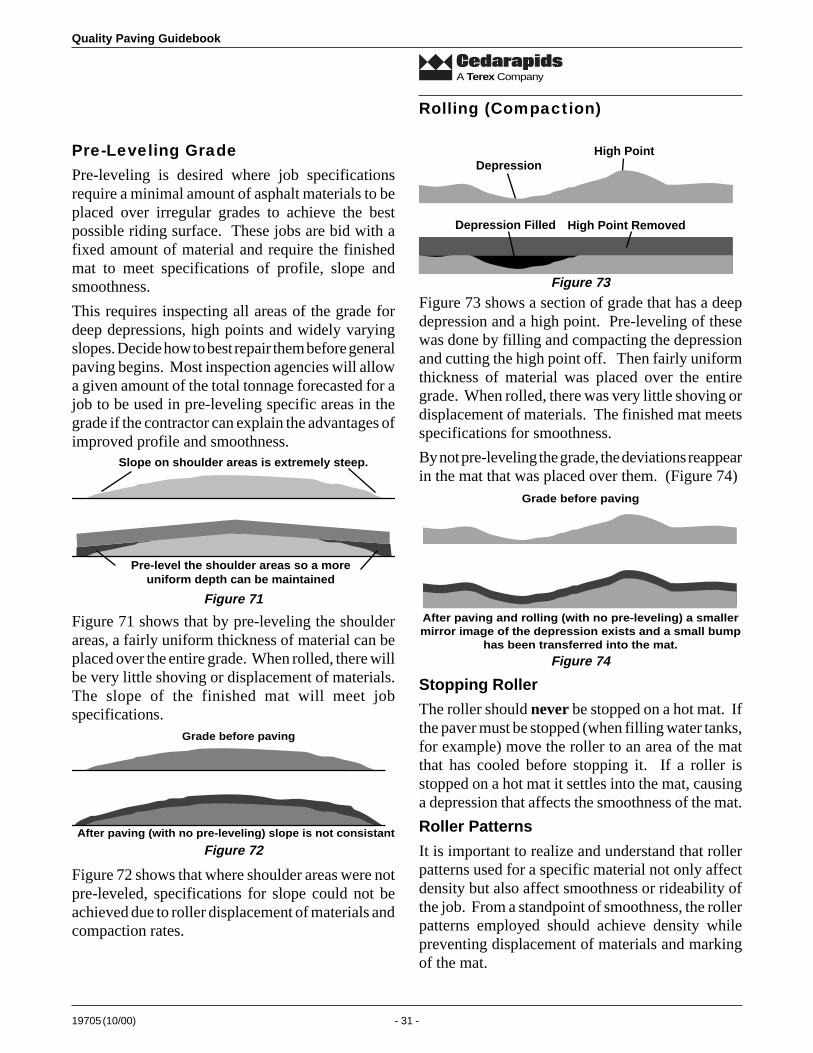
19705 (10/00) - 31 -
Quality Paving Guidebook
A Terex Company
Pre-Leveling GradePre-leveling is desired where job specificationsrequire a minimal amount of asphalt materials to beplaced over irregular grades to achieve the bestpossible riding surface. These jobs are bid with afixed amount of material and require the finishedmat to meet specifications of profile, slope andsmoothness.
This requires inspecting all areas of the grade fordeep depressions, high points and widely varyingslopes. Decide how to best repair them before generalpaving begins. Most inspection agencies will allowa given amount of the total tonnage forecasted for ajob to be used in pre-leveling specific areas in thegrade if the contractor can explain the advantages ofimproved profile and smoothness.
Rolling (Compaction)
Slope on shoulder areas is extremely steep.
Pre-level the shoulder areas so a moreuniform depth can be maintained
DepressionHigh Point
Depression Filled High Point Removed
Stopping Roller
The roller should never be stopped on a hot mat. Ifthe paver must be stopped (when filling water tanks,for example) move the roller to an area of the matthat has cooled before stopping it. If a roller isstopped on a hot mat it settles into the mat, causinga depression that affects the smoothness of the mat.
Roller Patterns
It is important to realize and understand that rollerpatterns used for a specific material not only affectdensity but also affect smoothness or rideability ofthe job. From a standpoint of smoothness, the rollerpatterns employed should achieve density whilepreventing displacement of materials and markingof the mat.
Figure 71
Figure 71 shows that by pre-leveling the shoulderareas, a fairly uniform thickness of material can beplaced over the entire grade. When rolled, there willbe very little shoving or displacement of materials.The slope of the finished mat will meet jobspecifications.
Grade before paving
After paving (with no pre-leveling) slope is not consistant
Figure 72
Figure 72 shows that where shoulder areas were notpre-leveled, specifications for slope could not beachieved due to roller displacement of materials andcompaction rates.
Figure 73
Figure 73 shows a section of grade that has a deepdepression and a high point. Pre-leveling of thesewas done by filling and compacting the depressionand cutting the high point off. Then fairly uniformthickness of material was placed over the entiregrade. When rolled, there was very little shoving ordisplacement of materials. The finished mat meetsspecifications for smoothness.
By not pre-leveling the grade, the deviations reappearin the mat that was placed over them. (Figure 74)
Grade before paving
After paving and rolling (with no pre-leveling) a smallermirror image of the depression exists and a small bump
has been transferred into the mat.
Figure 74
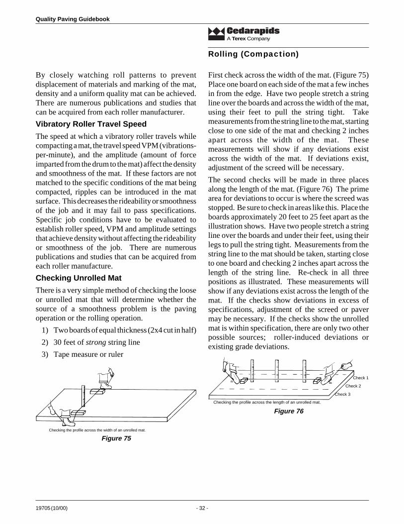
Quality Paving Guidebook
19705 (10/00) - 32 -
A Terex Company
By closely watching roll patterns to preventdisplacement of materials and marking of the mat,density and a uniform quality mat can be achieved.There are numerous publications and studies thatcan be acquired from each roller manufacturer.
Vibratory Roller Travel Speed
The speed at which a vibratory roller travels whilecompacting a mat, the travel speed VPM (vibrations-per-minute), and the amplitude (amount of forceimparted from the drum to the mat) affect the densityand smoothness of the mat. If these factors are notmatched to the specific conditions of the mat beingcompacted, ripples can be introduced in the matsurface. This decreases the rideability or smoothnessof the job and it may fail to pass specifications.Specific job conditions have to be evaluated toestablish roller speed, VPM and amplitude settingsthat achieve density without affecting the rideabilityor smoothness of the job. There are numerouspublications and studies that can be acquired fromeach roller manufacture.
Checking Unrolled Mat
There is a very simple method of checking the looseor unrolled mat that will determine whether thesource of a smoothness problem is the pavingoperation or the rolling operation.
1) Two boards of equal thickness (2x4 cut in half)
2) 30 feet of strong string line
3) Tape measure or ruler
Rolling (Compaction)
First check across the width of the mat. (Figure 75)Place one board on each side of the mat a few inchesin from the edge. Have two people stretch a stringline over the boards and across the width of the mat,using their feet to pull the string tight. Takemeasurements from the string line to the mat, startingclose to one side of the mat and checking 2 inchesapart across the width of the mat. Thesemeasurements will show if any deviations existacross the width of the mat. If deviations exist,adjustment of the screed will be necessary.
The second checks will be made in three placesalong the length of the mat. (Figure 76) The primearea for deviations to occur is where the screed wasstopped. Be sure to check in areas like this. Place theboards approximately 20 feet to 25 feet apart as theillustration shows. Have two people stretch a stringline over the boards and under their feet, using theirlegs to pull the string tight. Measurements from thestring line to the mat should be taken, starting closeto one board and checking 2 inches apart across thelength of the string line. Re-check in all threepositions as illustrated. These measurements willshow if any deviations exist across the length of themat. If the checks show deviations in excess ofspecifications, adjustment of the screed or pavermay be necessary. If the checks show the unrolledmat is within specification, there are only two otherpossible sources; roller-induced deviations orexisting grade deviations.
Checking the profile across the width of an unrolled mat.
Figure 75
Checking the profile across the length of an unrolled mat.
Check 3
Check 2
Check 1
Figure 76
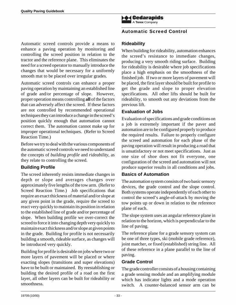
19705 (10/00) - 33 -
Quality Paving Guidebook
A Terex Company
Automatic screed controls provide a means toenhance a paving operation by monitoring andcontrolling the screed position in relation to thetractor and the reference plane. This eliminates theneed for a screed operator to manually introduce thechanges that would be necessary for a uniformlysmooth mat to be placed over irregular grades.
Automatic screed controls can enhance a properpaving operation by maintaining an established lineof grade and/or percentage of slope. However,proper operation means controlling all of the factorsthat can adversely affect the screed. If these factorsare not controlled by recommended operationaltechniques they can introduce a change in the screed’sposition quickly enough that automation cannotcorrect them. The automation cannot make up forimproper operational techniques. (Refer to ScreedReaction Time.)
Before we try to deal with the various components ofthe automatic screed controls we need to understandthe concepts of building profile and rideability, asthey relate to controlling the screed.
Building Profile
The screed inherently resists immediate changes indepth or slope and averages changes overapproximately five lengths of the tow arm. (Refer toScreed Reaction Time.) Job specifications thatrequire an exact thickness of material and/or slope atany given point in the grade, require the screed toreact very quickly to maintain its position in relationto the established line of grade and/or percentage ofslope. When building profile we over-correct thescreed to force it into changing depth very quickly tomaintain exact thickness and/or slope at given pointsin the grade. Building for profile is not necessarilybuilding a smooth, rideable surface, as changes willbe introduced very quickly.
Building for profile is desirable on jobs where two ormore layers of pavement will be placed or whereexacting slopes (transitions and super elevations)have to be built or maintained. By reestablishing orbuilding the desired profile of a road on the firstlayer, all other layers can be built for rideability orsmoothness.
Rideability
When building for rideability, automation enhancesthe screed’s resistance to immediate changes,producing a very smooth riding surface. Buildingfor rideability is desirable where job specificationsplace a high emphasis on the smoothness of thefinished job. If two or more layers of pavement willbe placed, the first layer should be built for profile toget the grade and slope to proper elevationspecifications. All other lifts should be built forrideability, to smooth out any deviations from theprevious lift.
Evaluation of Jobs
Evaluation of specifications and grade conditions ona job is extremely important if the paver andautomation are to be configured properly to producethe required results. Failure to properly configurethe screed and automation for each phase of thepaving operation will result in producing a road thatis unsatisfactory or not meet specifications. Just asone size of shoe does not fit everyone, oneconfiguration of the screed and automation will notproduce superior results in all conditions and jobs.
Basics of Automation
The automation system consists of two basic sensorydevices, the grade control and the slope control.Both systems operate independently of each other tocontrol the screed’s angle-of-attack by moving thetow points up or down in relation to the referenceplane of each.
The slope system uses an angular reference plane inrelation to the horizon, which is perpendicular to theline of paving.
The reference plane for a grade sensory system canbe one of three types, ski (mobile grade reference),joint matcher, or fixed (established) string line. Allof these reference in a plane parallel to the line ofpaving.
Grade Control
The grade controller consists of a housing containinga grade sensing module and an amplifying modulewhich has indicator lights and a mode operationswitch. A counter-balanced sensor arm can be
Automatic Screed Control
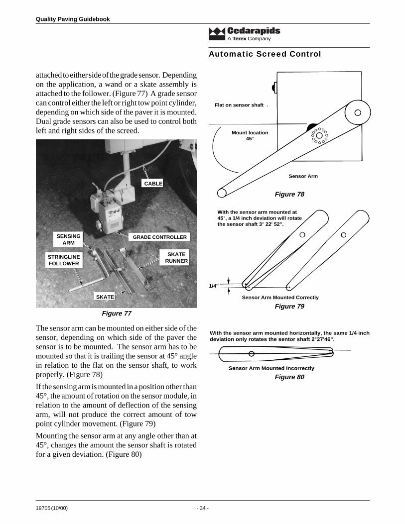
Quality Paving Guidebook
19705 (10/00) - 34 -
A Terex Company
attached to either side of the grade sensor. Dependingon the application, a wand or a skate assembly isattached to the follower. (Figure 77) A grade sensorcan control either the left or right tow point cylinder,depending on which side of the paver it is mounted.Dual grade sensors can also be used to control bothleft and right sides of the screed.
Automatic Screed Control
SENSINGARM
STRINGLINEFOLLOWER
SKATE
CABLE
GRADE CONTROLLER
SKATERUNNER
Figure 77
Flat on sensor shaft
Mount location45°
Sensor Arm
Figure 78
Sensor Arm Mounted Correctly
With the sensor arm mounted at45°, a 1/4 inch deviation will rotatethe sensor shaft 3° 22' 52".
1/4"
Figure 79
Sensor Arm Mounted Incorrectly
With the sensor arm mounted horizontally, the same 1/4 inchdeviation only rotates the sentor shaft 2°27'46".
Figure 80
The sensor arm can be mounted on either side of thesensor, depending on which side of the paver thesensor is to be mounted. The sensor arm has to bemounted so that it is trailing the sensor at 45° anglein relation to the flat on the sensor shaft, to workproperly. (Figure 78)
If the sensing arm is mounted in a position other than45°, the amount of rotation on the sensor module, inrelation to the amount of deflection of the sensingarm, will not produce the correct amount of towpoint cylinder movement. (Figure 79)
Mounting the sensor arm at any angle other than at45°, changes the amount the sensor shaft is rotatedfor a given deviation. (Figure 80)
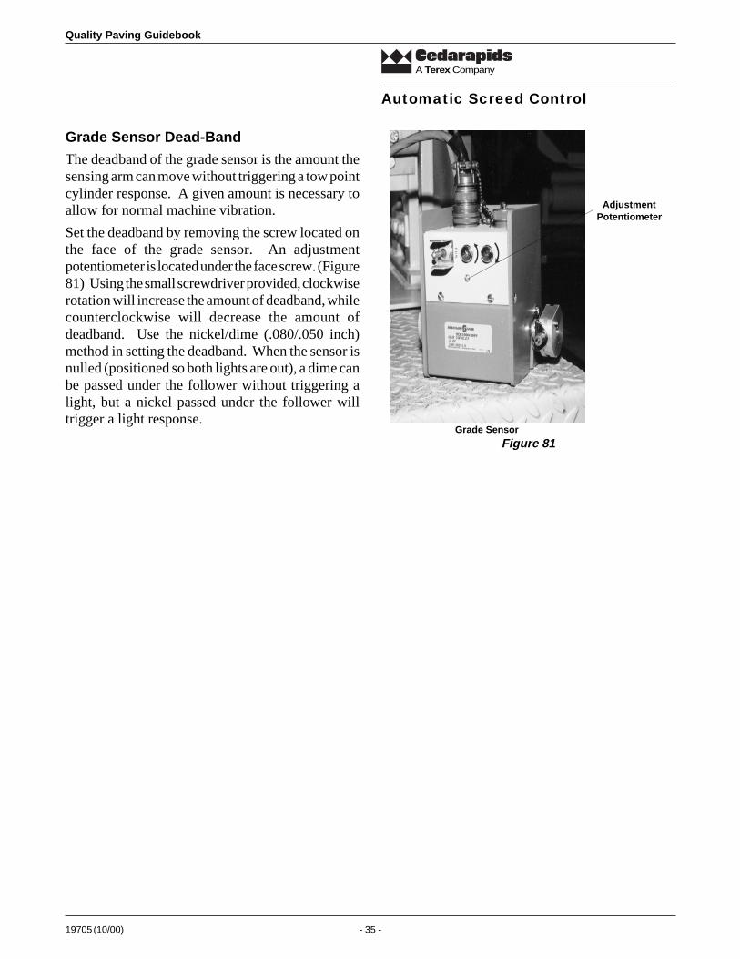
19705 (10/00) - 35 -
Quality Paving Guidebook
A Terex Company
Automatic Screed Control
Grade Sensor Dead-Band
The deadband of the grade sensor is the amount thesensing arm can move without triggering a tow pointcylinder response. A given amount is necessary toallow for normal machine vibration.
Set the deadband by removing the screw located onthe face of the grade sensor. An adjustmentpotentiometer is located under the face screw. (Figure81) Using the small screwdriver provided, clockwiserotation will increase the amount of deadband, whilecounterclockwise will decrease the amount ofdeadband. Use the nickel/dime (.080/.050 inch)method in setting the deadband. When the sensor isnulled (positioned so both lights are out), a dime canbe passed under the follower without triggering alight, but a nickel passed under the follower willtrigger a light response.
AdjustmentPotentiometer
Grade Sensor
Figure 81
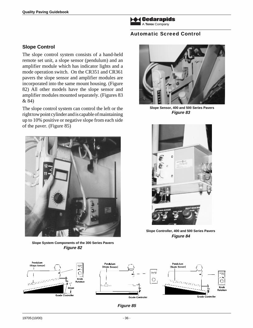
Quality Paving Guidebook
19705 (10/00) - 36 -
A Terex Company
Slope Control
The slope control system consists of a hand-heldremote set unit, a slope sensor (pendulum) and anamplifier module which has indicator lights and amode operation switch. On the CR351 and CR361pavers the slope sensor and amplifier modules areincorporated into the same mount housing. (Figure82) All other models have the slope sensor andamplifier modules mounted separately. (Figures 83& 84)
The slope control system can control the left or theright tow point cylinder and is capable of maintainingup to 10% positive or negative slope from each sideof the paver. (Figure 85)
Slope Sensor, 400 and 500 Series Pavers
Figure 83
Slope Controller, 400 and 500 Series Pavers
Slope System Components of the 300 Series Pavers
Figure 84
Figure 85
Figure 82
Automatic Screed Control
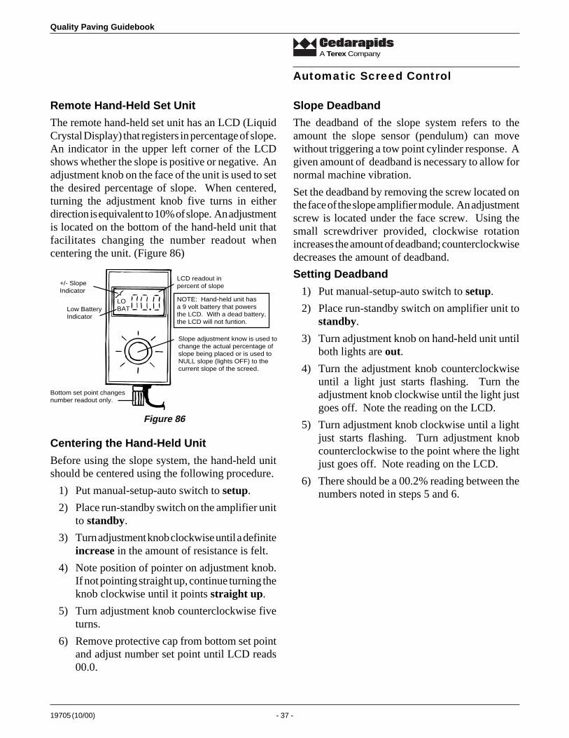
19705 (10/00) - 37 -
Quality Paving Guidebook
A Terex Company
Remote Hand-Held Set Unit
The remote hand-held set unit has an LCD (LiquidCrystal Display) that registers in percentage of slope.An indicator in the upper left corner of the LCDshows whether the slope is positive or negative. Anadjustment knob on the face of the unit is used to setthe desired percentage of slope. When centered,turning the adjustment knob five turns in eitherdirection is equivalent to 10% of slope. An adjustmentis located on the bottom of the hand-held unit thatfacilitates changing the number readout whencentering the unit. (Figure 86)
Slope Deadband
The deadband of the slope system refers to theamount the slope sensor (pendulum) can movewithout triggering a tow point cylinder response. Agiven amount of deadband is necessary to allow fornormal machine vibration.
Set the deadband by removing the screw located onthe face of the slope amplifier module. An adjustmentscrew is located under the face screw. Using thesmall screwdriver provided, clockwise rotationincreases the amount of deadband; counterclockwisedecreases the amount of deadband.
Setting Deadband
1) Put manual-setup-auto switch to setup.
2) Place run-standby switch on amplifier unit tostandby.
3) Turn adjustment knob on hand-held unit untilboth lights are out.
4) Turn the adjustment knob counterclockwiseuntil a light just starts flashing. Turn theadjustment knob clockwise until the light justgoes off. Note the reading on the LCD.
5) Turn adjustment knob clockwise until a lightjust starts flashing. Turn adjustment knobcounterclockwise to the point where the lightjust goes off. Note reading on the LCD.
6) There should be a 00.2% reading between thenumbers noted in steps 5 and 6.
Automatic Screed Control
LOBAT
+/- SlopeIndicator
Low BatteryIndicator
Bottom set point changesnumber readout only.
LCD readout inpercent of slope
NOTE: Hand-held unit hasa 9 volt battery that powersthe LCD. With a dead battery,the LCD will not funtion.
Slope adjustment know is used tochange the actual percentage ofslope being placed or is used toNULL slope (lights OFF) to thecurrent slope of the screed.
Figure 86
Centering the Hand-Held Unit
Before using the slope system, the hand-held unitshould be centered using the following procedure.
1) Put manual-setup-auto switch to setup.
2) Place run-standby switch on the amplifier unitto standby.
3) Turn adjustment knob clockwise until a definiteincrease in the amount of resistance is felt.
4) Note position of pointer on adjustment knob.If not pointing straight up, continue turning theknob clockwise until it points straight up.
5) Turn adjustment knob counterclockwise fiveturns.
6) Remove protective cap from bottom set pointand adjust number set point until LCD reads00.0.
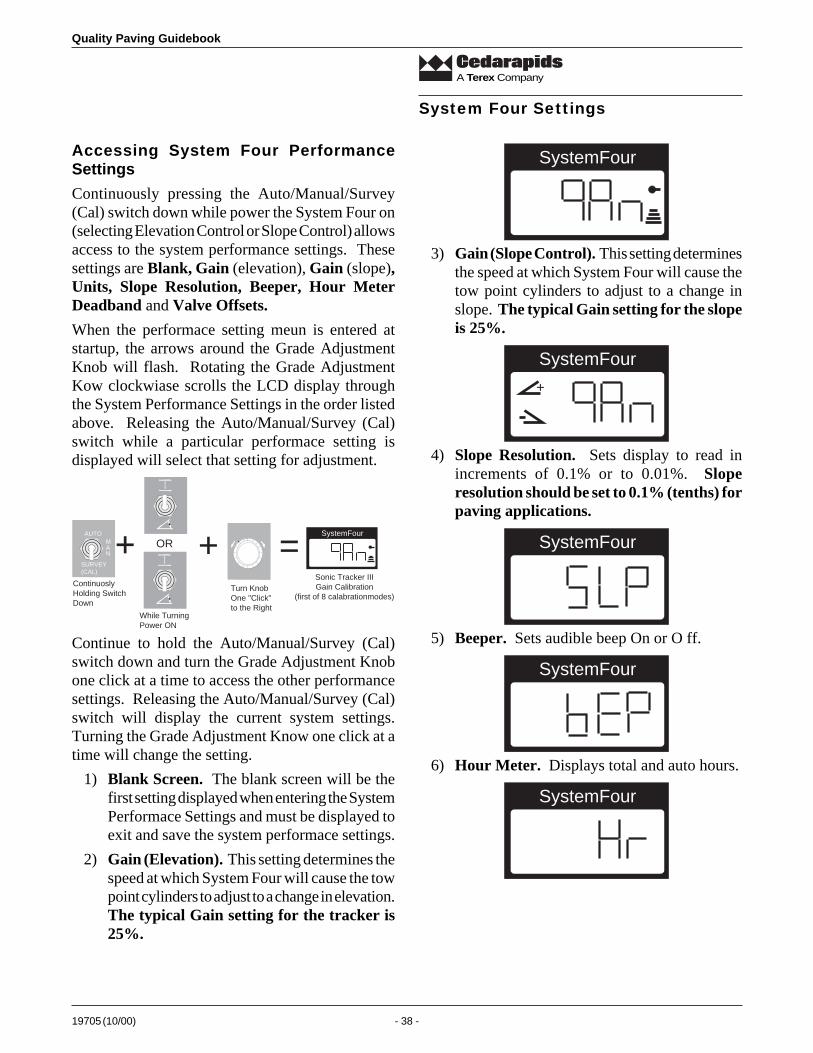
Quality Paving Guidebook
19705 (10/00) - 38 -
A Terex Company
System Four Settings
Accessing System Four PerformanceSettings
Continuously pressing the Auto/Manual/Survey(Cal) switch down while power the System Four on(selecting Elevation Control or Slope Control) allowsaccess to the system performance settings. Thesesettings are Blank, Gain (elevation), Gain (slope),Units, Slope Resolution, Beeper, Hour MeterDeadband and Valve Offsets.
When the performace setting meun is entered atstartup, the arrows around the Grade AdjustmentKnob will flash. Rotating the Grade AdjustmentKow clockwiase scrolls the LCD display throughthe System Performance Settings in the order listedabove. Releasing the Auto/Manual/Survey (Cal)switch while a particular performace setting isdisplayed will select that setting for adjustment.
SystemFourAUTOM
NA
SURVEY(CAL)
+ + =OR
While TurningPower ON
Turn KnobOne "Click"to the Right
Sonic Tracker IIIGain Calibration
(first of 8 calabrationmodes)
ContinuoslyHolding SwitchDown
Continue to hold the Auto/Manual/Survey (Cal)switch down and turn the Grade Adjustment Knobone click at a time to access the other performancesettings. Releasing the Auto/Manual/Survey (Cal)switch will display the current system settings.Turning the Grade Adjustment Know one click at atime will change the setting.
1) Blank Screen. The blank screen will be thefirst setting displayed when entering the SystemPerformace Settings and must be displayed toexit and save the system performace settings.
2) Gain (Elevation). This setting determines thespeed at which System Four will cause the towpoint cylinders to adjust to a change in elevation.The typical Gain setting for the tracker is25%.
SystemFour
3) Gain (Slope Control). This setting determinesthe speed at which System Four will cause thetow point cylinders to adjust to a change inslope. The typical Gain setting for the slopeis 25%.
SystemFour
+
4) Slope Resolution. Sets display to read inincrements of 0.1% or to 0.01%. Sloperesolution should be set to 0.1% (tenths) forpaving applications.
SystemFour
5) Beeper. Sets audible beep On or O ff.
SystemFour
6) Hour Meter. Displays total and auto hours.
SystemFour
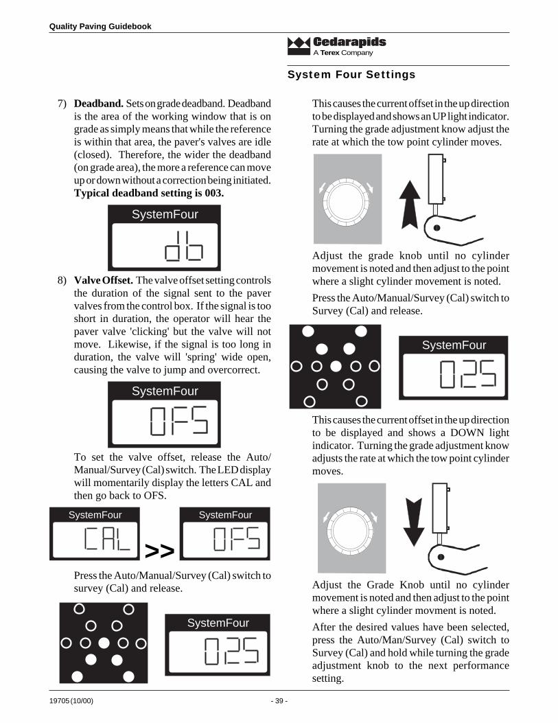
19705 (10/00) - 39 -
Quality Paving Guidebook
A Terex Company
7) Deadband. Sets on grade deadband. Deadbandis the area of the working window that is ongrade as simply means that while the referenceis within that area, the paver's valves are idle(closed). Therefore, the wider the deadband(on grade area), the more a reference can moveup or down without a correction being initiated.Typical deadband setting is 003.
SystemFour
8) Valve Offset. The valve offset setting controlsthe duration of the signal sent to the pavervalves from the control box. If the signal is tooshort in duration, the operator will hear thepaver valve 'clicking' but the valve will notmove. Likewise, if the signal is too long induration, the valve will 'spring' wide open,causing the valve to jump and overcorrect.
SystemFour
To set the valve offset, release the Auto/Manual/Survey (Cal) switch. The LED displaywill momentarily display the letters CAL andthen go back to OFS.
SystemFour SystemFour
>>Press the Auto/Manual/Survey (Cal) switch tosurvey (Cal) and release.
SystemFour
This causes the current offset in the up directionto be displayed and shows an UP light indicator.Turning the grade adjustment know adjust therate at which the tow point cylinder moves.
Adjust the grade knob until no cylindermovement is noted and then adjust to the pointwhere a slight cylinder movement is noted.
Press the Auto/Manual/Survey (Cal) switch toSurvey (Cal) and release.
SystemFour
This causes the current offset in the up directionto be displayed and shows a DOWN lightindicator. Turning the grade adjustment knowadjusts the rate at which the tow point cylindermoves.
Adjust the Grade Knob until no cylindermovement is noted and then adjust to the pointwhere a slight cylinder movment is noted.
After the desired values have been selected,press the Auto/Man/Survey (Cal) switch toSurvey (Cal) and hold while turning the gradeadjustment knob to the next performancesetting.
System Four Settings
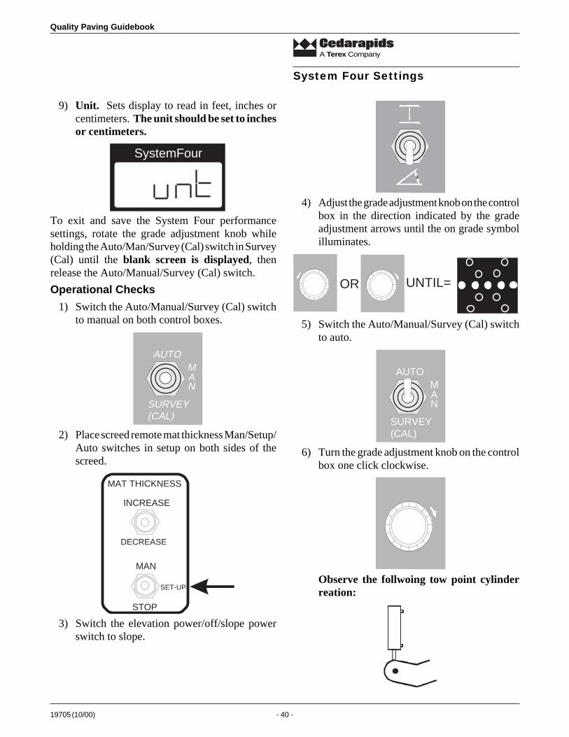
Quality Paving Guidebook
19705 (10/00) - 40 -
A Terex Company
System Four Settings
9) Unit. Sets display to read in feet, inches orcentimeters. The unit should be set to inchesor centimeters.
SystemFour
To exit and save the System Four performancesettings, rotate the grade adjustment knob whileholding the Auto/Man/Survey (Cal) switch in Survey(Cal) until the blank screen is displayed, thenrelease the Auto/Manual/Survey (Cal) switch.
Operational Checks
1) Switch the Auto/Manual/Survey (Cal) switchto manual on both control boxes.
AUTOM
NA
SURVEY(CAL)
2) Place screed remote mat thickness Man/Setup/Auto switches in setup on both sides of thescreed.
INCREASE
DECREASE
MAN
STOP
SET-UP
MAT THICKNESS
3) Switch the elevation power/off/slope powerswitch to slope.
4) Adjust the grade adjustment knob on the controlbox in the direction indicated by the gradeadjustment arrows until the on grade symbolilluminates.
OR UNTIL=
5) Switch the Auto/Manual/Survey (Cal) switchto auto.
AUTOM
NA
SURVEY(CAL)
6) Turn the grade adjustment knob on the controlbox one click clockwise.
Observe the follwoing tow point cylinderreation:
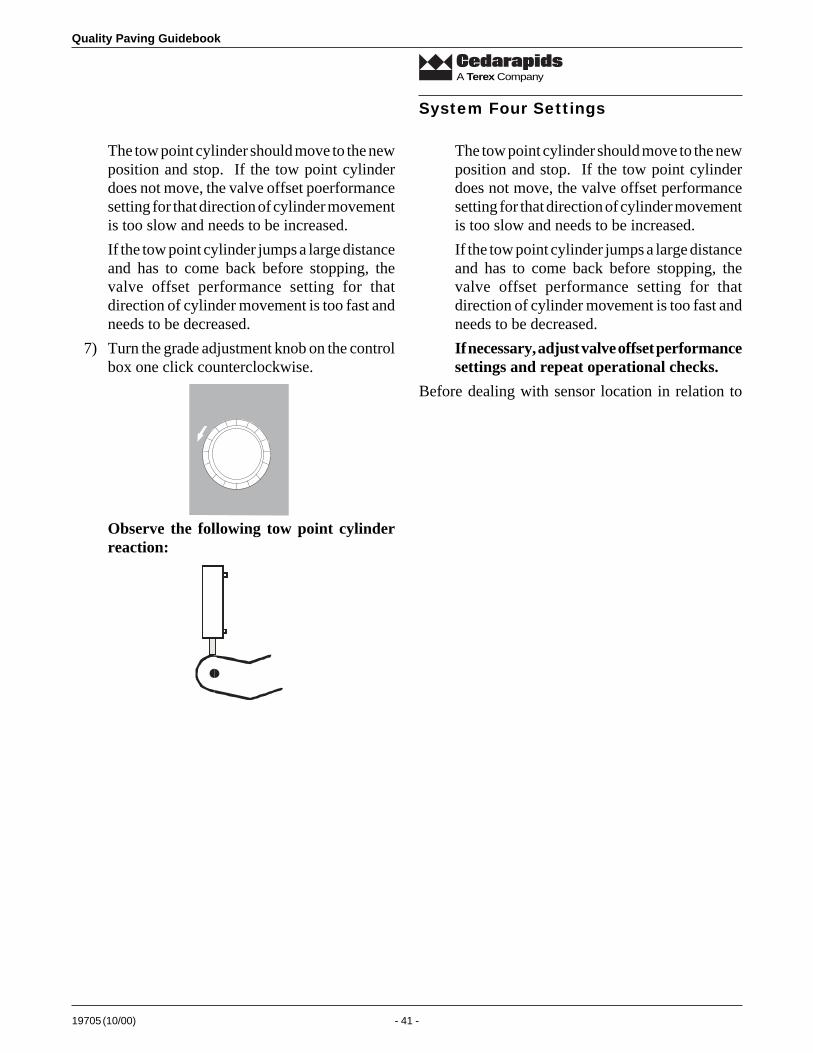
19705 (10/00) - 41 -
Quality Paving Guidebook
A Terex Company
The tow point cylinder should move to the newposition and stop. If the tow point cylinderdoes not move, the valve offset poerformancesetting for that direction of cylinder movementis too slow and needs to be increased.
If the tow point cylinder jumps a large distanceand has to come back before stopping, thevalve offset performance setting for thatdirection of cylinder movement is too fast andneeds to be decreased.
7) Turn the grade adjustment knob on the controlbox one click counterclockwise.
Observe the following tow point cylinderreaction:
The tow point cylinder should move to the newposition and stop. If the tow point cylinderdoes not move, the valve offset performancesetting for that direction of cylinder movementis too slow and needs to be increased.
If the tow point cylinder jumps a large distanceand has to come back before stopping, thevalve offset performance setting for thatdirection of cylinder movement is too fast andneeds to be decreased.
If necessary, adjust valve offset performancesettings and repeat operational checks.
Before dealing with sensor location in relation to
System Four Settings
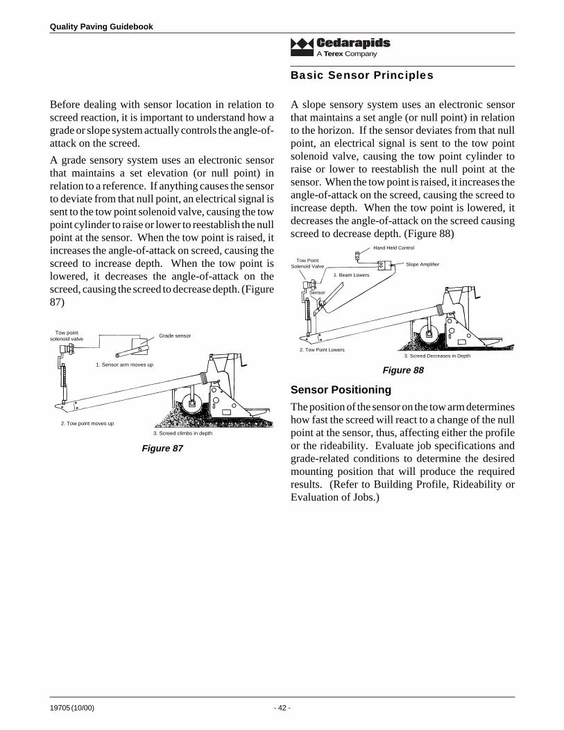
Quality Paving Guidebook
19705 (10/00) - 42 -
A Terex Company
Basic Sensor Principles
Before dealing with sensor location in relation toscreed reaction, it is important to understand how agrade or slope system actually controls the angle-of-attack on the screed.
A grade sensory system uses an electronic sensorthat maintains a set elevation (or null point) inrelation to a reference. If anything causes the sensorto deviate from that null point, an electrical signal issent to the tow point solenoid valve, causing the towpoint cylinder to raise or lower to reestablish the nullpoint at the sensor. When the tow point is raised, itincreases the angle-of-attack on screed, causing thescreed to increase depth. When the tow point islowered, it decreases the angle-of-attack on thescreed, causing the screed to decrease depth. (Figure87)
A slope sensory system uses an electronic sensorthat maintains a set angle (or null point) in relationto the horizon. If the sensor deviates from that nullpoint, an electrical signal is sent to the tow pointsolenoid valve, causing the tow point cylinder toraise or lower to reestablish the null point at thesensor. When the tow point is raised, it increases theangle-of-attack on the screed, causing the screed toincrease depth. When the tow point is lowered, itdecreases the angle-of-attack on the screed causingscreed to decrease depth. (Figure 88)
Grade sensor
1. Sensor arm moves up
Tow pointsolenoid valve
2. Tow point moves up
3. Screed climbs in depth
Figure 87
Hand Held Control
Slope AmplifierTow Point
Solenoid Valve
1. Beam Lowers
Sensor
2. Tow Point Lowers3. Screed Decreases in Depth
Figure 88
Sensor Positioning
The position of the sensor on the tow arm determineshow fast the screed will react to a change of the nullpoint at the sensor, thus, affecting either the profileor the rideability. Evaluate job specifications andgrade-related conditions to determine the desiredmounting position that will produce the requiredresults. (Refer to Building Profile, Rideability orEvaluation of Jobs.)
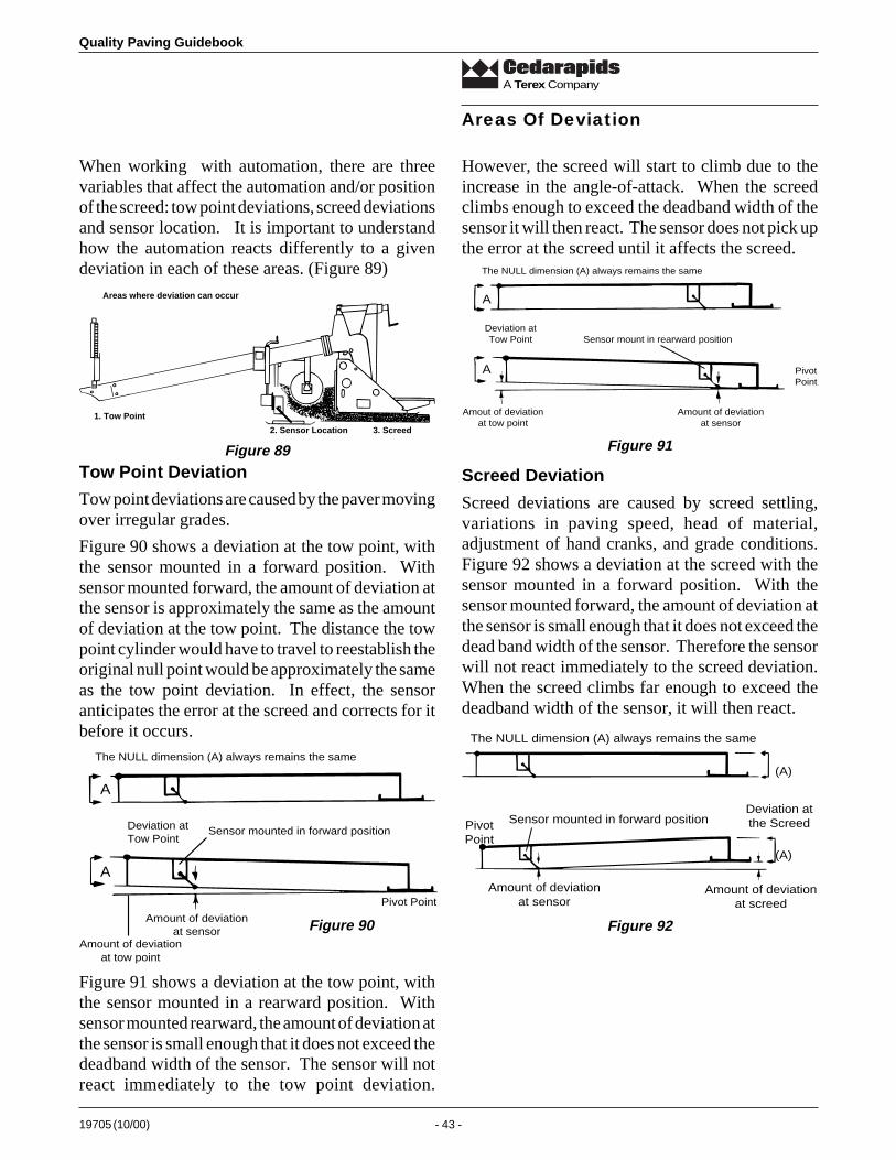
19705 (10/00) - 43 -
Quality Paving Guidebook
A Terex Company
However, the screed will start to climb due to theincrease in the angle-of-attack. When the screedclimbs enough to exceed the deadband width of thesensor it will then react. The sensor does not pick upthe error at the screed until it affects the screed.
Areas Of Deviation
Screed Deviation
Screed deviations are caused by screed settling,variations in paving speed, head of material,adjustment of hand cranks, and grade conditions.Figure 92 shows a deviation at the screed with thesensor mounted in a forward position. With thesensor mounted forward, the amount of deviation atthe sensor is small enough that it does not exceed thedead band width of the sensor. Therefore the sensorwill not react immediately to the screed deviation.When the screed climbs far enough to exceed thedeadband width of the sensor, it will then react.
Deviation atthe Screed
(A)
(A)
The NULL dimension (A) always remains the same
PivotPoint
Sensor mounted in forward position
Amount of deviationat sensor
Amount of deviationat screed
When working with automation, there are threevariables that affect the automation and/or positionof the screed: tow point deviations, screed deviationsand sensor location. It is important to understandhow the automation reacts differently to a givendeviation in each of these areas. (Figure 89)
Areas where deviation can occur
1. Tow Point
2. Sensor Location 3. Screed
Figure 89
Tow Point Deviation
Tow point deviations are caused by the paver movingover irregular grades.
Figure 90 shows a deviation at the tow point, withthe sensor mounted in a forward position. Withsensor mounted forward, the amount of deviation atthe sensor is approximately the same as the amountof deviation at the tow point. The distance the towpoint cylinder would have to travel to reestablish theoriginal null point would be approximately the sameas the tow point deviation. In effect, the sensoranticipates the error at the screed and corrects for itbefore it occurs.
A
A
Deviation atTow Point
The NULL dimension (A) always remains the same
Sensor mounted in forward position
Pivot Point
Amount of deviationat sensor
Amount of deviationat tow point
Figure 90
A
A
The NULL dimension (A) always remains the same
Deviation atTow Point
Amout of deviationat tow point
Amount of deviationat sensor
Sensor mount in rearward position
PivotPoint
Figure 91
Figure 92
Figure 91 shows a deviation at the tow point, withthe sensor mounted in a rearward position. Withsensor mounted rearward, the amount of deviation atthe sensor is small enough that it does not exceed thedeadband width of the sensor. The sensor will notreact immediately to the tow point deviation.
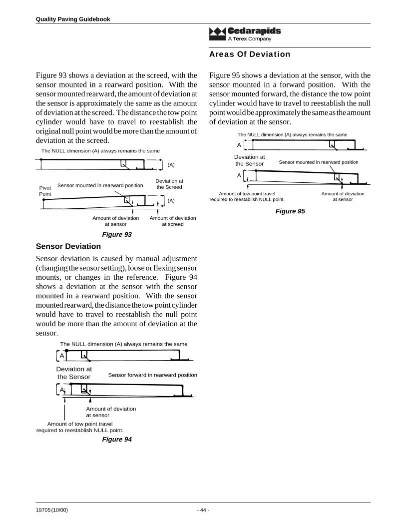
Quality Paving Guidebook
19705 (10/00) - 44 -
A Terex Company
Figure 93 shows a deviation at the screed, with thesensor mounted in a rearward position. With thesensor mounted rearward, the amount of deviation atthe sensor is approximately the same as the amountof deviation at the screed. The distance the tow pointcylinder would have to travel to reestablish theoriginal null point would be more than the amount ofdeviation at the screed.
Figure 95 shows a deviation at the sensor, with thesensor mounted in a forward position. With thesensor mounted forward, the distance the tow pointcylinder would have to travel to reestablish the nullpoint would be approximately the same as the amountof deviation at the sensor.
Areas Of Deviation
Sensor Deviation
Sensor deviation is caused by manual adjustment(changing the sensor setting), loose or flexing sensormounts, or changes in the reference. Figure 94shows a deviation at the sensor with the sensormounted in a rearward position. With the sensormounted rearward, the distance the tow point cylinderwould have to travel to reestablish the null pointwould be more than the amount of deviation at thesensor.
A
A
Deviation atthe Sensor
The NULL dimension (A) always remains the same
Sensor mounted in rearward position
Amount of tow point travelrequired to reestablish NULL point.
Amount of deviationat sensor
Deviation atthe Screed
(A)
(A)
The NULL dimension (A) always remains the same
PivotPoint
Sensor mounted in rearward position
Amount of deviationat sensor
Amount of deviationat screed
Figure 93
A
A
Deviation atthe Sensor
The NULL dimension (A) always remains the same
Sensor forward in rearward position
Amount of tow point travelrequired to reestablish NULL point.
Amount of deviationat sensor
Figure 94
Figure 95
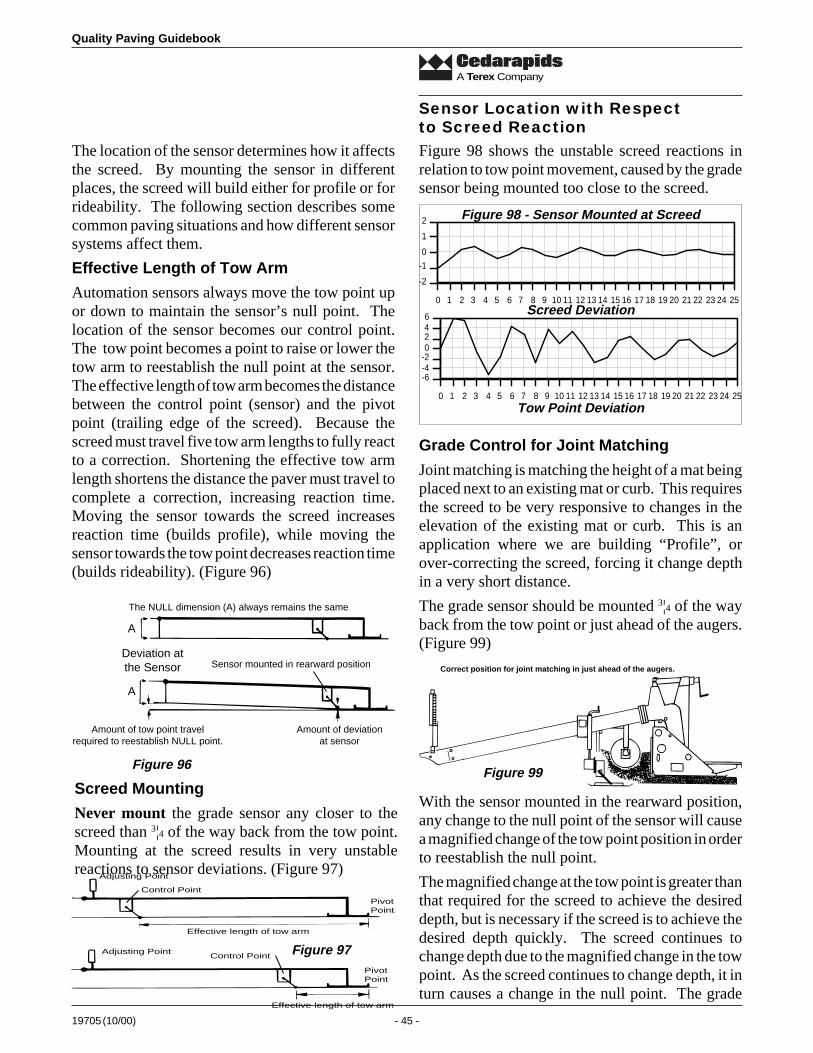
19705 (10/00) - 45 -
Quality Paving Guidebook
A Terex Company
Adjusting Point
PivotPoint
Control Point
Effective length of tow arm
Effective length of tow arm
PivotPoint
Control PointAdjusting Point
The location of the sensor determines how it affectsthe screed. By mounting the sensor in differentplaces, the screed will build either for profile or forrideability. The following section describes somecommon paving situations and how different sensorsystems affect them.
Effective Length of Tow Arm
Automation sensors always move the tow point upor down to maintain the sensor’s null point. Thelocation of the sensor becomes our control point.The tow point becomes a point to raise or lower thetow arm to reestablish the null point at the sensor.The effective length of tow arm becomes the distancebetween the control point (sensor) and the pivotpoint (trailing edge of the screed). Because thescreed must travel five tow arm lengths to fully reactto a correction. Shortening the effective tow armlength shortens the distance the paver must travel tocomplete a correction, increasing reaction time.Moving the sensor towards the screed increasesreaction time (builds profile), while moving thesensor towards the tow point decreases reaction time(builds rideability). (Figure 96)
Sensor Location with Respectto Screed ReactionFigure 98 shows the unstable screed reactions inrelation to tow point movement, caused by the gradesensor being mounted too close to the screed.
Grade Control for Joint Matching
Joint matching is matching the height of a mat beingplaced next to an existing mat or curb. This requiresthe screed to be very responsive to changes in theelevation of the existing mat or curb. This is anapplication where we are building “Profile”, orover-correcting the screed, forcing it change depthin a very short distance.
The grade sensor should be mounted 3¦4 of the wayback from the tow point or just ahead of the augers.(Figure 99)
With the sensor mounted in the rearward position,any change to the null point of the sensor will causea magnified change of the tow point position in orderto reestablish the null point.
The magnified change at the tow point is greater thanthat required for the screed to achieve the desireddepth, but is necessary if the screed is to achieve thedesired depth quickly. The screed continues tochange depth due to the magnified change in the towpoint. As the screed continues to change depth, it inturn causes a change in the null point. The grade
A
A
Deviation atthe Sensor
The NULL dimension (A) always remains the same
Sensor mounted in rearward position
Amount of tow point travelrequired to reestablish NULL point.
Amount of deviationat sensor
Figure 98 - Sensor Mounted at Screed
-2
-1
0
1
2
0 1 2 3 4 5 6 7 8 9 10 11 12 13 14 15 16 17 18 19 20 21 22 23 24 25Screed Deviation
-6-4-20246
0 1 2 3 4 5 6 7 8 9 10 11 12 13 14 15 16 17 18 19 20 21 22 23 24 25Tow Point Deviation
Figure 96
Screed Mounting
Never mount the grade sensor any closer to thescreed than 3¦4 of the way back from the tow point.Mounting at the screed results in very unstablereactions to sensor deviations. (Figure 97)
Correct position for joint matching in just ahead of the augers.
Figure 99
Figure 97
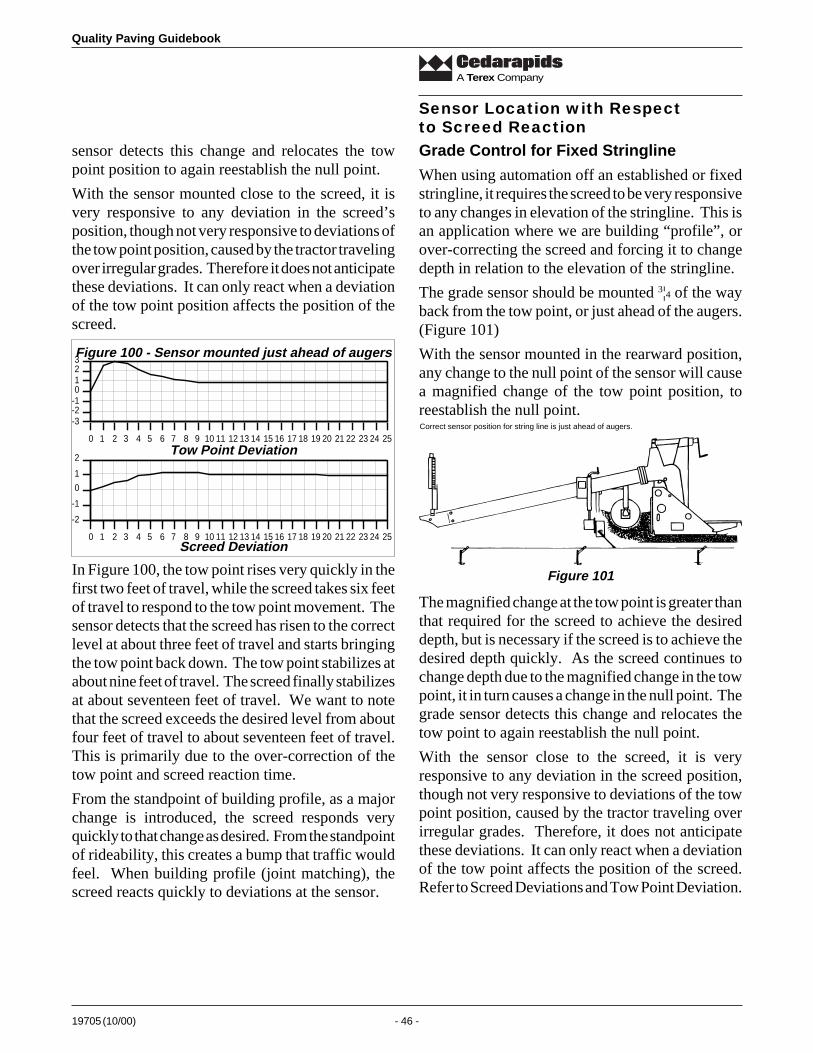
Quality Paving Guidebook
19705 (10/00) - 46 -
A Terex Company
-2
-1
0
1
2
0 1 2 3 4 5 6 7 8 9 10 11 12 13 14 15 16 17 18 19 20 21 22 23 24 25
sensor detects this change and relocates the towpoint position to again reestablish the null point.
With the sensor mounted close to the screed, it isvery responsive to any deviation in the screed’sposition, though not very responsive to deviations ofthe tow point position, caused by the tractor travelingover irregular grades. Therefore it does not anticipatethese deviations. It can only react when a deviationof the tow point position affects the position of thescreed.
Grade Control for Fixed Stringline
When using automation off an established or fixedstringline, it requires the screed to be very responsiveto any changes in elevation of the stringline. This isan application where we are building “profile”, orover-correcting the screed and forcing it to changedepth in relation to the elevation of the stringline.
The grade sensor should be mounted 3¦4 of the wayback from the tow point, or just ahead of the augers.(Figure 101)
With the sensor mounted in the rearward position,any change to the null point of the sensor will causea magnified change of the tow point position, toreestablish the null point.
Sensor Location with Respectto Screed Reaction
In Figure 100, the tow point rises very quickly in thefirst two feet of travel, while the screed takes six feetof travel to respond to the tow point movement. Thesensor detects that the screed has risen to the correctlevel at about three feet of travel and starts bringingthe tow point back down. The tow point stabilizes atabout nine feet of travel. The screed finally stabilizesat about seventeen feet of travel. We want to notethat the screed exceeds the desired level from aboutfour feet of travel to about seventeen feet of travel.This is primarily due to the over-correction of thetow point and screed reaction time.
From the standpoint of building profile, as a majorchange is introduced, the screed responds veryquickly to that change as desired. From the standpointof rideability, this creates a bump that traffic wouldfeel. When building profile (joint matching), thescreed reacts quickly to deviations at the sensor.
Figure 100 - Sensor mounted just ahead of augers
-3-2-10123
0 1 2 3 4 5 6 7 8 9 10 11 12 13 14 15 16 17 18 19 20 21 22 23 24 25Tow Point Deviation
Screed Deviation
Correct sensor position for string line is just ahead of augers.
Figure 101
The magnified change at the tow point is greater thanthat required for the screed to achieve the desireddepth, but is necessary if the screed is to achieve thedesired depth quickly. As the screed continues tochange depth due to the magnified change in the towpoint, it in turn causes a change in the null point. Thegrade sensor detects this change and relocates thetow point to again reestablish the null point.
With the sensor close to the screed, it is veryresponsive to any deviation in the screed position,though not very responsive to deviations of the towpoint position, caused by the tractor traveling overirregular grades. Therefore, it does not anticipatethese deviations. It can only react when a deviationof the tow point affects the position of the screed.Refer to Screed Deviations and Tow Point Deviation.
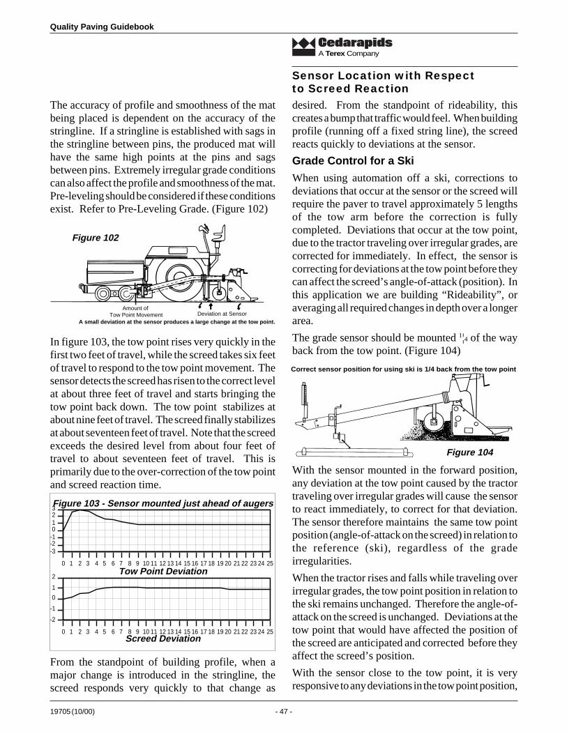
19705 (10/00) - 47 -
Quality Paving Guidebook
A Terex Company
The accuracy of profile and smoothness of the matbeing placed is dependent on the accuracy of thestringline. If a stringline is established with sags inthe stringline between pins, the produced mat willhave the same high points at the pins and sagsbetween pins. Extremely irregular grade conditionscan also affect the profile and smoothness of the mat.Pre-leveling should be considered if these conditionsexist. Refer to Pre-Leveling Grade. (Figure 102)
Sensor Location with Respectto Screed Reaction
In figure 103, the tow point rises very quickly in thefirst two feet of travel, while the screed takes six feetof travel to respond to the tow point movement. Thesensor detects the screed has risen to the correct levelat about three feet of travel and starts bringing thetow point back down. The tow point stabilizes atabout nine feet of travel. The screed finally stabilizesat about seventeen feet of travel. Note that the screedexceeds the desired level from about four feet oftravel to about seventeen feet of travel. This isprimarily due to the over-correction of the tow pointand screed reaction time.
From the standpoint of building profile, when amajor change is introduced in the stringline, thescreed responds very quickly to that change as
desired. From the standpoint of rideability, thiscreates a bump that traffic would feel. When buildingprofile (running off a fixed string line), the screedreacts quickly to deviations at the sensor.
Grade Control for a Ski
When using automation off a ski, corrections todeviations that occur at the sensor or the screed willrequire the paver to travel approximately 5 lengthsof the tow arm before the correction is fullycompleted. Deviations that occur at the tow point,due to the tractor traveling over irregular grades, arecorrected for immediately. In effect, the sensor iscorrecting for deviations at the tow point before theycan affect the screed’s angle-of-attack (position). Inthis application we are building “Rideability”, oraveraging all required changes in depth over a longerarea.
The grade sensor should be mounted 1¦4 of the wayback from the tow point. (Figure 104)
With the sensor mounted in the forward position,any deviation at the tow point caused by the tractortraveling over irregular grades will cause the sensorto react immediately, to correct for that deviation.The sensor therefore maintains the same tow pointposition (angle-of-attack on the screed) in relation tothe reference (ski), regardless of the gradeirregularities.
When the tractor rises and falls while traveling overirregular grades, the tow point position in relation tothe ski remains unchanged. Therefore the angle-of-attack on the screed is unchanged. Deviations at thetow point that would have affected the position ofthe screed are anticipated and corrected before theyaffect the screed’s position.
With the sensor close to the tow point, it is veryresponsive to any deviations in the tow point position,
-2
-1
0
1
2
0 1 2 3 4 5 6 7 8 9 10 11 12 13 14 15 16 17 18 19 20 21 22 23 24 25
Figure 103 - Sensor mounted just ahead of augers
-3-2-10123
0 1 2 3 4 5 6 7 8 9 10 11 12 13 14 15 16 17 18 19 20 21 22 23 24 25Tow Point Deviation
Screed Deviation
A small deviation at the sensor produces a large change at the tow point.Deviation at Sensor
Amount of Tow Point Movement
Figure 102
Correct sensor position for using ski is 1/4 back from the tow point
Figure 104
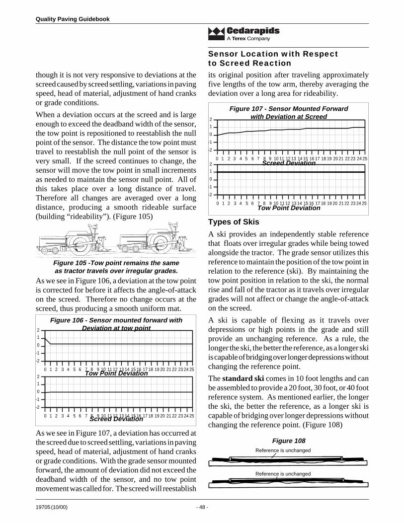
Quality Paving Guidebook
19705 (10/00) - 48 -
A Terex Company
though it is not very responsive to deviations at thescreed caused by screed settling, variations in pavingspeed, head of material, adjustment of hand cranksor grade conditions.
When a deviation occurs at the screed and is largeenough to exceed the deadband width of the sensor,the tow point is repositioned to reestablish the nullpoint of the sensor. The distance the tow point musttravel to reestablish the null point of the sensor isvery small. If the screed continues to change, thesensor will move the tow point in small incrementsas needed to maintain the sensor null point. All ofthis takes place over a long distance of travel.Therefore all changes are averaged over a longdistance, producing a smooth rideable surface(building “rideability”). (Figure 105)
its original position after traveling approximatelyfive lengths of the tow arm, thereby averaging thedeviation over a long area for rideability.
As we see in Figure 106, a deviation at the tow pointis corrected for before it affects the angle-of-attackon the screed. Therefore no change occurs at thescreed, thus producing a smooth uniform mat.
As we see in Figure 107, a deviation has occurred atthe screed due to screed settling, variations in pavingspeed, head of material, adjustment of hand cranksor grade conditions. With the grade sensor mountedforward, the amount of deviation did not exceed thedeadband width of the sensor, and no tow pointmovement was called for. The screed will reestablish
Types of Skis
A ski provides an independently stable referencethat floats over irregular grades while being towedalongside the tractor. The grade sensor utilizes thisreference to maintain the position of the tow point inrelation to the reference (ski). By maintaining thetow point position in relation to the ski, the normalrise and fall of the tractor as it travels over irregulargrades will not affect or change the angle-of-attackon the screed.
A ski is capable of flexing as it travels overdepressions or high points in the grade and stillprovide an unchanging reference. As a rule, thelonger the ski, the better the reference, as a longer skiis capable of bridging over longer depressions withoutchanging the reference point.
The standard ski comes in 10 foot lengths and canbe assembled to provide a 20 foot, 30 foot, or 40 footreference system. As mentioned earlier, the longerthe ski, the better the reference, as a longer ski iscapable of bridging over longer depressions withoutchanging the reference point. (Figure 108)
Sensor Location with Respectto Screed Reaction
-2
-1
0
1
2
0 1 2 3 4 5 6 7 8 9 10 11 12 13 14 15 16 17 18 19 20 21 22 23 24 25
-2
-1
0
1
2
0 1 2 3 4 5 6 7 8 9 10 11 12 13 14 15 16 17 18 19 20 21 22 23 24 25
Figure 106 - Sensor mounted forward withDeviation at tow point
Tow Point Deviation
Screed Deviation
Figure 107 - Sensor Mounted Forwardwith Deviation at Screed
-2
-1
0
1
2
0 1 2 3 4 5 6 7 8 9 10 11 12 13 14 15 16 17 18 19 20 21 22 23 24 25
-2
-1
0
1
2
0 1 2 3 4 5 6 7 8 9 10 11 12 13 14 15 16 17 18 19 20 21 22 23 24 25
Screed Deviation
Tow Point Deviation
Reference is unchanged
Reference is unchanged
Figure 108
Figure 105 -Tow point remains the sameas tractor travels over irregular grades.
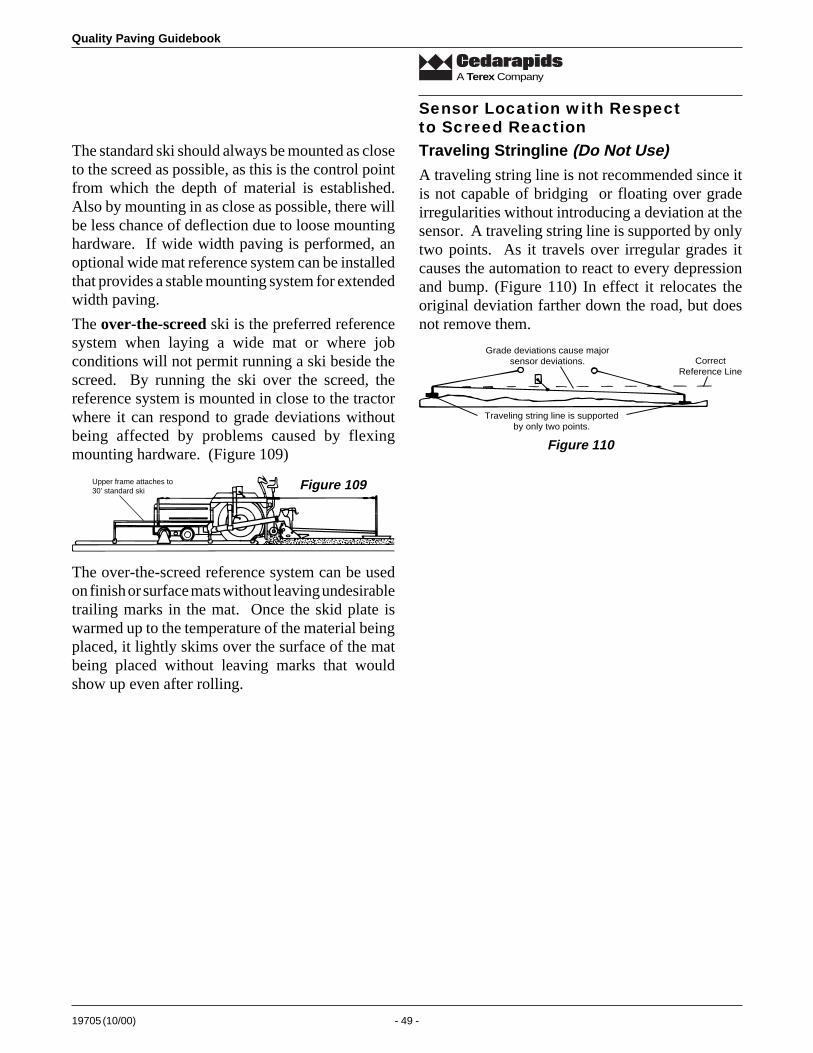
19705 (10/00) - 49 -
Quality Paving Guidebook
A Terex Company
The standard ski should always be mounted as closeto the screed as possible, as this is the control pointfrom which the depth of material is established.Also by mounting in as close as possible, there willbe less chance of deflection due to loose mountinghardware. If wide width paving is performed, anoptional wide mat reference system can be installedthat provides a stable mounting system for extendedwidth paving.
The over-the-screed ski is the preferred referencesystem when laying a wide mat or where jobconditions will not permit running a ski beside thescreed. By running the ski over the screed, thereference system is mounted in close to the tractorwhere it can respond to grade deviations withoutbeing affected by problems caused by flexingmounting hardware. (Figure 109)
Traveling Stringline (Do Not Use)A traveling string line is not recommended since itis not capable of bridging or floating over gradeirregularities without introducing a deviation at thesensor. A traveling string line is supported by onlytwo points. As it travels over irregular grades itcauses the automation to react to every depressionand bump. (Figure 110) In effect it relocates theoriginal deviation farther down the road, but doesnot remove them.
Sensor Location with Respectto Screed Reaction
Grade deviations cause majorsensor deviations. Correct
Reference Line
Traveling string line is supportedby only two points.
Figure 110
Upper frame attaches to30' standard ski Figure 109
The over-the-screed reference system can be usedon finish or surface mats without leaving undesirabletrailing marks in the mat. Once the skid plate iswarmed up to the temperature of the material beingplaced, it lightly skims over the surface of the matbeing placed without leaving marks that wouldshow up even after rolling.
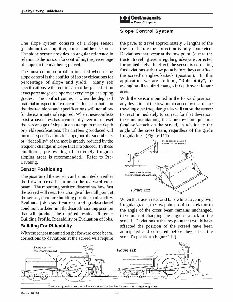
Quality Paving Guidebook
19705 (10/00) - 50 -
A Terex Company
The slope system consists of a slope sensor(pendulum), an amplifier, and a hand-held set unit.The slope sensor provides an angular reference inrelation to the horizon for controlling the percentageof slope on the mat being placed.
The most common problem incurred when usingslope control is the conflict of job specifications forpercentage of slope and yield. Many jobspecifications will require a mat be placed at anexact percentage of slope over very irregular slopinggrades. The conflict comes in when the depth ofmaterial in a specific area becomes thicker to maintainthe desired slope and specifications will not allowfor the extra material required. When these conflictsexist, a paver crew has to constantly override or resetthe percentage of slope in an attempt to meet depthor yield specifications. The mat being produced willnot meet specifications for slope, and the smoothnessor “rideability” of the mat is greatly reduced by thefrequent changes in slope that introduced. In theseconditions, pre-leveling of extremely irregularsloping areas is recommended. Refer to Pre-Leveling.
Sensor Positioning
The position of the sensor can be mounted on eitherthe forward cross beam or on the rearward crossbeam. The mounting position determines how fastthe screed will react to a change of the null point atthe sensor, therefore building profile or rideability.Evaluate job specifications and grade-relatedconditions to determine the desired mounting positionthat will produce the required results. Refer toBuilding Profile, Rideability or Evaluation of Jobs.
Building For Rideability
With the sensor mounted on the forward cross beam,corrections to deviations at the screed will require
the paver to travel approximately 5 lengths of thetow arm before the correction is fully completed.Deviations that occur at the tow point, (due to thetractor traveling over irregular grades) are correctedfor immediately. In effect, the sensor is correctingfor deviations at the tow point before they can affectthe screed’s angle-of-attack (position). In thisapplication we are building “Rideability”, oraveraging all required changes in depth over a longerarea.
With the sensor mounted in the forward position,any deviation at the tow point caused by the tractortraveling over irregular grades will cause the sensorto react immediately to correct for that deviation,therefore maintaining the same tow point position(angle-of-attack on the screed) in relation to theangle of the cross beam, regardless of the gradeirregularities. (Figure 111)
Slope Control System
Slope sensormounted forward
Tow point position remains the same as the tractor travels over irregular grades.
Slope sensor mountedforward for "rideability"
Sensor reacts to anyangular change of crossbeam
Figure 111
Figure 112
When the tractor rises and falls while traveling overirregular grades, the tow point position in relation tothe angle of the cross beam remains unchanged,therefore not changing the angle-of-attack on thescreed. Deviations at the tow point that would haveaffected the position of the screed have beenanticipated and corrected before they affect thescreed’s position. (Figure 112)
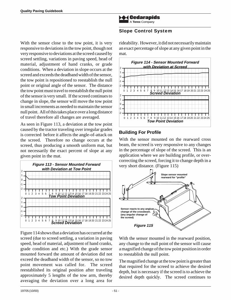
19705 (10/00) - 51 -
Quality Paving Guidebook
A Terex Company
With the sensor close to the tow point, it is veryresponsive to deviations in the tow point, though notvery responsive to deviations at the screed caused byscreed settling, variations in paving speed, head ofmaterial, adjustment of hand cranks, or gradeconditions. When a deviation in slope occurs at thescreed and exceeds the deadband width of the sensor,the tow point is repositioned to reestablish the nullpoint or original angle of the sensor. The distancethe tow point must travel to reestablish the null pointof the sensor is very small. If the screed continues tochange in slope, the sensor will move the tow pointin small increments as needed to maintain the sensornull point. All of this takes place over a long distanceof travel therefore all changes are averaged.
As seen in Figure 113, a deviation at the tow pointcaused by the tractor traveling over irregular gradesis corrected before it affects the angle-of-attack onthe screed. Therefore no change occurs at thescreed, thus producing a smooth uniform mat, butnot necessarily the exact percent of slope at anygiven point in the mat.
rideability. However, it did not necessarily maintainan exact percentage of slope at any given point in themat.
Slope Control System
Figure 113 - Sensor Mounted Forwardwith Deviation at Tow Point
-2
-1
0
1
2
0 1 2 3 4 5 6 7 8 9 10 11 12 13 14 15 16 17 18 19 20 21 22 23 24 25Tow Point Deviation
-2
-1
0
1
2
0 1 2 3 4 5 6 7 8 9 10 11 12 13 14 15 16 17 18 19 20 21 22 23 24 25Screed Deviation
Figure 114 shows that a deviation has occurred at thescreed (due to screed settling, a variation in pavingspeed, head of material, adjustment of hand cranks,grade condition and etc.) With the grade sensormounted forward the amount of deviation did notexceed the deadband width of the sensor, so no towpoint movement was called for. The screedreestablished its original position after travelingapproximately 5 lengths of the tow arm, therebyaveraging the deviation over a long area for
-2
-1
0
1
2
0 1 2 3 4 5 6 7 8 9 10 11 12 13 14 15 16 17 18 19 20 21 22 23 24 25
Figure 114 - Sensor Mounted Forwardwith Deviation at Screed
Screed Deviation
-2
-1
0
1
2
0 1 2 3 4 5 6 7 8 9 10 11 12 13 14 15 16 17 18 19 20 21 22 23 24 25Tow Point Deviation
Building For Profile
With the sensor mounted on the rearward crossbeam, the screed is very responsive to any changesin the percentage of slope of the screed. This is anapplication where we are building profile, or over-correcting the screed, forcing it to change depth in avery short distance. (Figure 115)
Slope sensor mountedrearward for "profile"
Sensor reacts to any angluarchange of the crossbeam.(any angular change ofthe screed)
Figure 115
With the sensor mounted in the rearward position,any change to the null point of the sensor will causea magnified change of the tow point position in orderto reestablish the null point.
The magnified change at the tow point is greater thanthat required for the screed to achieve the desireddepth, but is necessary if the screed is to achieve thedesired depth quickly. The screed continues to
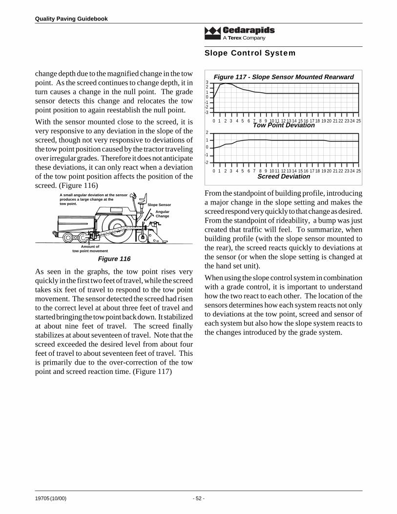
Quality Paving Guidebook
19705 (10/00) - 52 -
A Terex Company
change depth due to the magnified change in the towpoint. As the screed continues to change depth, it inturn causes a change in the null point. The gradesensor detects this change and relocates the towpoint position to again reestablish the null point.
With the sensor mounted close to the screed, it isvery responsive to any deviation in the slope of thescreed, though not very responsive to deviations ofthe tow point position caused by the tractor travelingover irregular grades. Therefore it does not anticipatethese deviations, it can only react when a deviationof the tow point position affects the position of thescreed. (Figure 116)
Slope Control System
Amount oftow point movement
Slope Sensor
AngularChange
A small angular deviation at the sensorproduces a large change at thetow point.
Figure 116
As seen in the graphs, the tow point rises veryquickly in the first two feet of travel, while the screedtakes six feet of travel to respond to the tow pointmovement. The sensor detected the screed had risento the correct level at about three feet of travel andstarted bringing the tow point back down. It stabilizedat about nine feet of travel. The screed finallystabilizes at about seventeen of travel. Note that thescreed exceeded the desired level from about fourfeet of travel to about seventeen feet of travel. Thisis primarily due to the over-correction of the towpoint and screed reaction time. (Figure 117)
-3-2-10123
0 1 2 3 4 5 6 7 8 9 10 11 12 13 14 15 16 17 18 19 20 21 22 23 24 25
Figure 117 - Slope Sensor Mounted Rearward
Tow Point Deviation
-2
-1
0
1
2
0 1 2 3 4 5 6 7 8 9 10 11 12 13 14 15 16 17 18 19 20 21 22 23 24 25Screed Deviation
From the standpoint of building profile, introducinga major change in the slope setting and makes thescreed respond very quickly to that change as desired.From the standpoint of rideability, a bump was justcreated that traffic will feel. To summarize, whenbuilding profile (with the slope sensor mounted tothe rear), the screed reacts quickly to deviations atthe sensor (or when the slope setting is changed atthe hand set unit).
When using the slope control system in combinationwith a grade control, it is important to understandhow the two react to each other. The location of thesensors determines how each system reacts not onlyto deviations at the tow point, screed and sensor ofeach system but also how the slope system reacts tothe changes introduced by the grade system.
19705 (10/00) - 53 -
Quality Paving Guidebook
A Terex Company
Ski and Slope (Sensor Forward)
When a combination of ski and slope are utilized,mounting both grade and slope sensors forwardresults in better rideability. If a deviation occurs atthe tow point on the side being controlled by thegrade sensor, the grade sensor reacts immediately toreestablish the original tow point position in relationto the ski. Therefore the angle of the cross beamremains unchanged and the slope sensor does notreact. If a deviation occurs at the tow point on theside being controlled by the slope sensor, the slopesensor reacts immediately to reestablish the originalangle of the cross beam. In effect the slope controlmaintains the tow point position much like the gradecontrol system does when run off a ski. Thiscombination of grade and slope will anticipatedeviations that would occur at the screed and correctsfor them before they occur. Refer to Tow PointDeviation with sensor mounted forward.
With the sensors close to the tow point, they are veryresponsive to any deviations in the tow point’sposition, though not very responsive to deviations atthe screed caused by screed settling, variations inpaving speed, head of material, adjustment of handcranks, grade conditions, etc. Refer to ScreedDeviation with sensor mounted forward.
Ski and Slope (Sensor Rearward)
When utilizing a slope sensor (mounted rearward)with a ski, the grade system builds rideability whilethe slope system corrects for change at the screed.Refer to Tow Point Deviation with sensor mountedrearward. This combination is not overly responsiveto irregular grades, but will even out deviations,providing rideability. It is, however, very responsiveto deviations of slope at the screed. If a deviationoccurs at the screed, the sensor will cause a largechange of the tow point position to reestablish thenull point of the slope sensor. Refer to ScreedDeviation with sensor mounted rearward.
Joint Matcher and Slope (Sensor Forward)
When combining a slope sensor (mounted forward)and a joint matcher (with the grade sensor mountedrearward) the grade system builds profile while theslope system builds rideability.
If a deviation occurs at the tow point on the sidecontrolled by the slope sensor, the slope sensorreacts immediately to reestablish the original angleof the cross beam, maintaining the tow point position.Therefore it is anticipates deviations that wouldoccur at the screed and corrects for them before theyoccur. Refer to Tow Point Deviation with sensormounted forward. With the slope sensor close to thetow point, it is very responsive to any deviations inthe tow point position, though not very responsive todeviations at the screed, caused by screed settling,variations in paving speed, head of material,adjustment of hand cranks, grade conditions, etc.Refer to Screed Deviation with sensor mountedforward.
If a deviation occurs at the grade sensor, the sensorwill cause a large change of the tow point position onthe grade side to reestablish the null point of thegrade sensor. Refer to Screed Deviation with sensormounted rearward. This large change of the towpoint position on the grade side in turn changes theangle of the cross beam. The slope sensor detectsthis and changes the tow point position on the slopeside an equal amount in the same direction toreestablish the null point of the slope sensor. Ineffect, a small deviation at the grade sensor hascaused a magnified change of both grade and slopetow points. Refer to Sensor Deviation with sensormounted rearward.
Joint Matcher and Slope (Sensor Rearward)
When combining a slope sensor (mounted rearward)and a joint matcher (with the grade sensor mountedrearward) both the grade and slope systems buildprofile. If a deviation occurs at the grade sensor, thesensor will cause a large change of the tow pointposition on the grade side to reestablish the nullpoint of the grade sensor. Refer to Sensor Deviationwith sensor mounted rearward. The slope sensorwill not react to the deviation at the grade sensor
Reactions(Combinations of Grade and Slope)

Quality Paving Guidebook
19705 (10/00) - 54 -
A Terex Company
until the change that was introduced to the grade sidetow point causes a change at the screed. Then it willalso introduce a large change in the tow point positionon the slope control side. Refer to Screed Deviationwith sensor mounted rearward. If a deviation occursat the screed, the slope sensor will cause a largechange of the tow point position on the slope side toreestablish the null point of the slope sensor. Referto Screed Deviation with sensor mounted rearward.
Reactions(Combinations of Grade and Slope)When the slope and grade sensors are mountedrearward, they are not very responsive to deviationsat the tow points caused by the tractor traveling overirregular grades. They can only react after a towpoint deviation has caused a change at the screed.Refer to Tow Point Deviation with sensor mountedrearward.
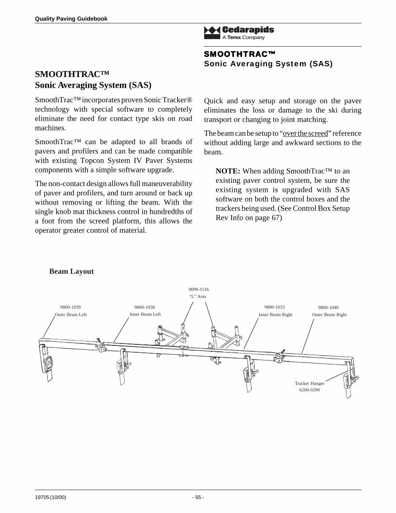
19705 (10/00) - 55 -
Quality Paving Guidebook
A Terex Company
Outer Beam Left Outer Beam RightInner Beam Left Inner Beam Right
Tracker Hanger
“L” Arm
9090-1116
9800-1039 9800-1038 9800-1033 9800-1040
6200-0290
Beam Layout
SMOOTHTRAC™Sonic Averaging System (SAS)
SmoothTrac™ incorporates proven Sonic Tracker®technology with special software to completelyeliminate the need for contact type skis on roadmachines.
SmoothTrac™ can be adapted to all brands ofpavers and profilers and can be made compatiblewith existing Topcon System IV Paver Systemscomponents with a simple software upgrade.
The non-contact design allows full maneuverabilityof paver and profilers, and turn around or back upwithout removing or lifting the beam. With thesingle knob mat thickness control in hundredths ofa foot from the screed platform, this allows theoperator greater control of material.
Quick and easy setup and storage on the pavereliminates the loss or damage to the ski duringtransport or changing to joint matching.
The beam can be setup to “over the screed” referencewithout adding large and awkward sections to thebeam.
NOTE: When adding SmoothTrac™ to anexisting paver control system, be sure theexisting system is upgraded with SASsoftware on both the control boxes and thetrackers being used. (See Control Box SetupRev Info on page 67)
SMOOTHTRAC™SMOOTHTRAC™SMOOTHTRAC™SMOOTHTRAC™SMOOTHTRAC™Sonic Averaging System (SAS)
Quality Paving Guidebook
19705 (10/00) - 56 -
A Terex Company
SMOOTHTRAC™SMOOTHTRAC™SMOOTHTRAC™SMOOTHTRAC™SMOOTHTRAC™Sonic Averaging System (SAS)
Safety PrecautionsSafety PrecautionsSafety PrecautionsSafety PrecautionsSafety Precautions
1. Read and become familiar with themanufacturer’s operations manual, includingsafety information before installing or usingTopcon System Four.
2. Working around heavy constructionequipment can be dangerous. Always useextreme caution on the job site.
Warning - Do not stand or sit on machineparts meant for operation.
3. The mandrel should be grounded before workingon or around the paver.
4. Do not attach System Four components to thepaver while the engine is running.
5. Do not allow any System Four component tolimit the visibility of the operator in an unsafemanner.
6. Use tie-wraps supplied with System Four tokeep hoses and wires secured and away fromwear or pinch joints.
7. Use eye protection when welding, cutting, orgrinding is being done on the machine.
8. Hydraulic lines can be under extreme pressureeven when the machine is turned off. Whenworking on or near hydraulic lines, protectyourself at all times and wear protective clothing.
Warning - Relieve all pressure in thehydraulic lines before disconnecting orremoving any lines, fittings, or relatedcomponents. If injury does occur, seekmedical assistance immediately. Consultthe profiler OEM Operator’s Manual fordetails.
9. When using laser control, avoid direct exposureto your eyes.
Caution - Do not stare into the laserbeam or view the beam directly withoptical equipment.
10.When welding, always use appropriate weldingprecautions and practices. Use shielding toprevent onlookers from staring into the light.
11. After welding, all affected areas should be paintedwith a rust inhibitor.
Notice - Disconnect all Topcon systemelectrical cables prior to welding on themachine.
Warning - Do not weld near hydrauliclines or on any equipment when inoperation.
Notice - All mounting bracket welds must besecure and strong to prevent the sensorequipment from vibrating excessively orfrom becoming detached at the weld duringoperation.
Notice - Keep the carrying case dry at alltimes. Do not allow moisture to get insidethe case. Moisture trapped in the case canadversely affect components. If moisure doesenter the carrying case, leave it open andallow it to dry thoroughtly before storingany components.
12. To prevent vandalism or theft, do not leave theremovable Topcon components on the machineduring off hours. Remove the components afterwork and store in carrying case.
19705 (10/00) - 57 -
Quality Paving Guidebook
A Terex Company
SMOOTHTRAC™SMOOTHTRAC™SMOOTHTRAC™SMOOTHTRAC™SMOOTHTRAC™Sonic Averaging System (SAS)
InstallationInstallationInstallationInstallationInstallation
1. During installation, in order to accurately alignthe beam assembly onto the pivot post, use thecenter portion of the beam or equivalent weldfixture.
2. Both attachment posts must be mounted (welded)perpendicular to upper surface of the tow arm,and parallel to each other.
3. Prior to installation of the L arms, align lockingcollar on the end gate post with the stop collar onthe tow arm pivot post.
4. Orientation of the L arms are dependent uponthe height alignment of both collars. The L armscan be installed with 16” post in either theupright or downward pointing direction in orderto raise or lower the beam and place the trackerwithin the required sensing range.
5. Loosely coil the cable about the beam sectionsand use the cable clamps to prevent saggingloops that might create a safety hazard.
6. After initial installation, assure a good path toground by partially tightening handles and lockbolts, and then moving all folding joints in andout. This should remove all paint which couldprevent good grounding.
NOTE: A BAD GROUND WILL CAUSEUNSTABLE LIGHTS ON TRACKERS.
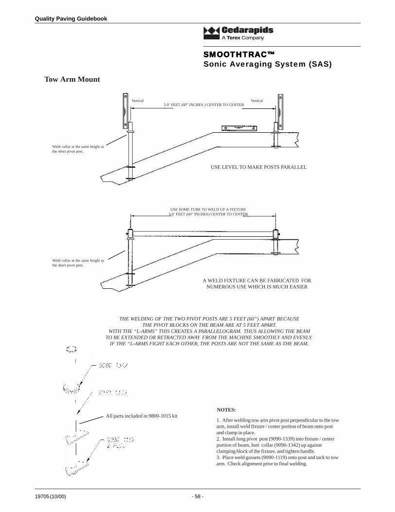
Quality Paving Guidebook
19705 (10/00) - 58 -
A Terex Company
1. After welding tow arm pivot post perpendicular to the towarm, install weld fixture / center portion of beam onto postand clamp in place.2. Install long pivot post (9090-1339) into fixture / centerportion of beam, butt collar (9090-1342) up againstclamping block of the fixture, and tighten handle.3. Place weld gussets (9090-1119) onto post and tack to towarm. Check alignment prior to final welding.
NOTES:All parts included in 9800-1015 kit
Tow Arm Mount
THE WELDING OF THE TWO PIVOT POSTS ARE 5 FEET (60”) APART BECAUSE THE PIVOT BLOCKS ON THE BEAM ARE AT 5 FEET APART.
WITH THE “L-ARMS” THIS CREATES A PARALLELOGRAM. THUS ALLOWING THE BEAMTO BE EXTENDED OR RETRACTED AWAY FROM THE MACHINE SMOOTHLY AND EVENLY.
IF THE “L-ARMS FIGHT EACH OTHER, THE POSTS ARE NOT THE SAME AS THE BEAM.
Weld collar at the same height asthe short pivot post.
Vertical Vertical5.0’ FEET (60” INCHES ) CENTER TO CENTER
Weld collar at the same height asthe short pivot post.
USE SOME TUBE TO WELD UP A FIXTURE5.0’ FEET (60” INCHES) CENTER TO CENTER
USE LEVEL TO MAKE POSTS PARALLEL
A WELD FIXTURE CAN BE FABRICATED FORNUMEROUS USE WHICH IS MUCH EASIER
SMOOTHTRAC™SMOOTHTRAC™SMOOTHTRAC™SMOOTHTRAC™SMOOTHTRAC™Sonic Averaging System (SAS)
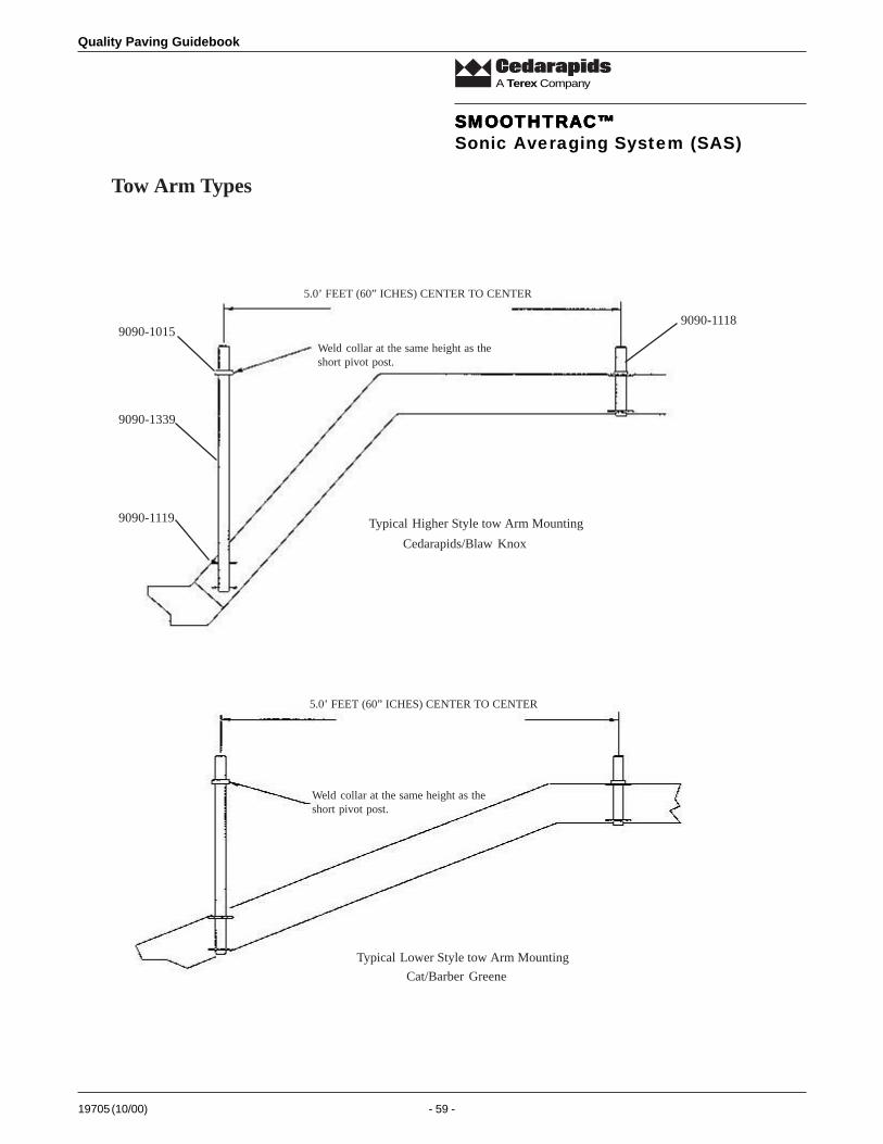
19705 (10/00) - 59 -
Quality Paving Guidebook
A Terex Company
Tow Arm Types
9090-1015
9090-1339
9090-1119
9090-1118
Cedarapids/Blaw Knox
5.0’ FEET (60” ICHES) CENTER TO CENTER
Weld collar at the same height as theshort pivot post.
Typical Higher Style tow Arm Mounting
5.0’ FEET (60” ICHES) CENTER TO CENTER
Weld collar at the same height as theshort pivot post.
Cat/Barber Greene
Typical Lower Style tow Arm Mounting
SMOOTHTRAC™SMOOTHTRAC™SMOOTHTRAC™SMOOTHTRAC™SMOOTHTRAC™Sonic Averaging System (SAS)

Quality Paving Guidebook
19705 (10/00) - 60 -
A Terex Company
CR300 Series Pavers
SMOOTHTRAC™SMOOTHTRAC™SMOOTHTRAC™SMOOTHTRAC™SMOOTHTRAC™Sonic Averaging System (SAS)

19705 (10/00) - 61 -
Quality Paving Guidebook
A Terex Company
CR400/CR500 Series Pavers
SMOOTHTRAC™SMOOTHTRAC™SMOOTHTRAC™SMOOTHTRAC™SMOOTHTRAC™Sonic Averaging System (SAS)
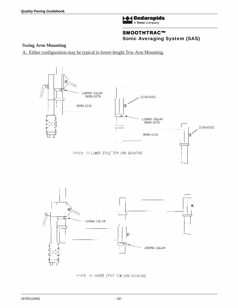
Quality Paving Guidebook
19705 (10/00) - 62 -
A Terex Company
A. Either configuration may be typical to lower-height Tow Arm Mounting.
9090-1116
9090-1116
9090-1078
9090-1078
2130-0102
2130-0102
Swing Arm Mounting
SMOOTHTRAC™SMOOTHTRAC™SMOOTHTRAC™SMOOTHTRAC™SMOOTHTRAC™Sonic Averaging System (SAS)
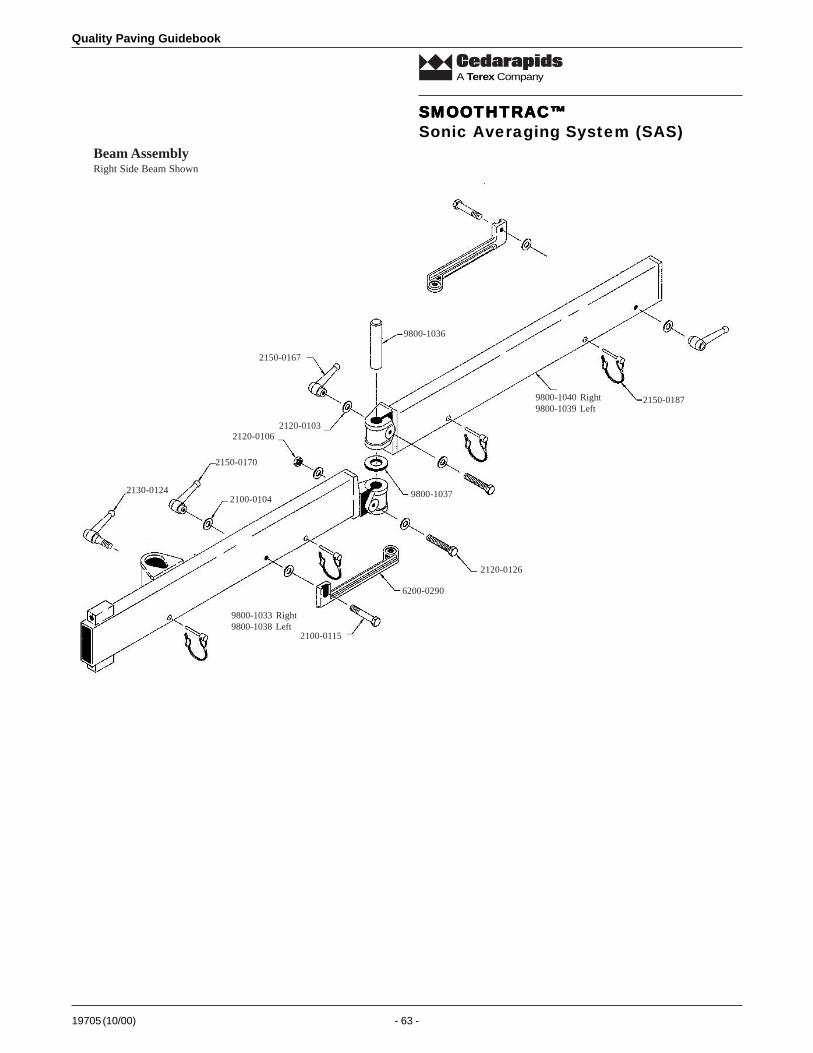
19705 (10/00) - 63 -
Quality Paving Guidebook
A Terex Company
Beam Assembly
NO
TE
*A
pply
Ant
i-Se
ize
to a
ll th
read
s an
d P
ivot
Pin
s
2150-0167
2150-0170
2100-0104
2100-0115
2120-0106
6200-0290
2120-0126
2130-0124
2120-0103
9800-1036
9800-1040 Right9800-1039 Left
2150-0187
9800-1033 Right9800-1038 Left
9800-1037
Right Side Beam Shown
SMOOTHTRAC™SMOOTHTRAC™SMOOTHTRAC™SMOOTHTRAC™SMOOTHTRAC™Sonic Averaging System (SAS)
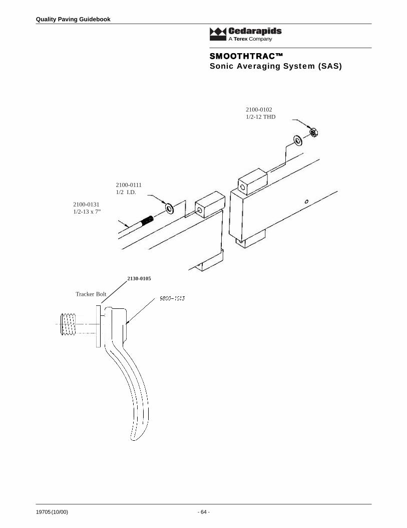
Quality Paving Guidebook
19705 (10/00) - 64 -
A Terex Company
2100-01311/2-13 x 7”
2100-01111/2
I.D.
2100-01021/2-12 THD
Tracker Bolt
2130-0105
SMOOTHTRAC™SMOOTHTRAC™SMOOTHTRAC™SMOOTHTRAC™SMOOTHTRAC™Sonic Averaging System (SAS)

19705 (10/00) - 65 -
Quality Paving Guidebook
A Terex Company
SAS CableThe 9060-5232 SAS Coil cable was designed to give the operator the felexability of relocating the the Sonic Trackers on the beam bydrilling new mounting holes and moving the Tracker hanger.
A B F K L A B F K L A B F K L A B F K L
880200680337
CO
MM
A
CO
MM
BV
SWIT
GR
OU
ND
11
23
32
44
Physical LocationPolling Sequence
SMOOTHTRAC™SMOOTHTRAC™SMOOTHTRAC™SMOOTHTRAC™SMOOTHTRAC™Sonic Averaging System (SAS)
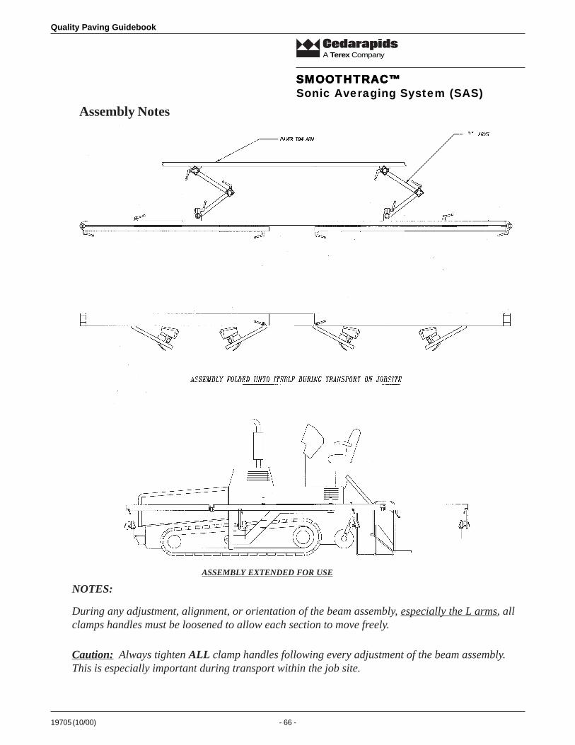
Quality Paving Guidebook
19705 (10/00) - 66 -
A Terex Company
During any adjustment, alignment, or orientation of the beam assembly, especially the L arms, allclamps handles must be loosened to allow each section to move freely.
Caution: Always tighten ALL clamp handles following every adjustment of the beam assembly.This is especially important during transport within the job site.
NOTES:
ASSEMBLY EXTENDED FOR USE
Assembly Notes
SMOOTHTRAC™SMOOTHTRAC™SMOOTHTRAC™SMOOTHTRAC™SMOOTHTRAC™Sonic Averaging System (SAS)

19705 (10/00) - 67 -
Quality Paving Guidebook
A Terex Company
Refer to the Topcon Paver System Four Operator’s Manual (7010-0118) for accessing the System Four Performancesettings. Confirm the Control Box Rev is 3.7 or higher and the Tracker Rev is 2.1 or higher (Both Control Box andTrackers should be labeled with SAS stickers)..After entering the performance menu follow the steps below:
1. Set SS to equal the number of Trackers being used.Range OFF/2-10
2. Lower gains if system response is too quick causing rapid corrections.3. The frequency setting in the technicians menu may need to be lowered to 3, if the beam has an osciliation
when the machine is sitting still.
Control Box Setup Instructions for SAS Installation
SMOOTHTRAC™SMOOTHTRAC™SMOOTHTRAC™SMOOTHTRAC™SMOOTHTRAC™Sonic Averaging System (SAS)

Quality Paving Guidebook
19705 (10/00) - 68 -
A Terex Company
Placement of Sonic Averaging System The center connection point of the SAS is the balance point. The position of the balance point to the tow arm is verycritical. By moving the balance point, the performance of the system is greatly affected. The balance point of the beamshould be located 1/3 to 2/3 the distance from the rear of the screed to the tow point cylinder.
By placing the balance point near the back 1/3 (close to the screed), the systems will have a faster reaction time. Byplacing the balance point closer to the 2/3 point (near the tow point cylinder), the system will have a slower reactiontime. For mainline paving, a slower reaction time is desired.
To determine where to position the SAS on your paver, start by measuring the length of the tow arm. Divide the totallength by three. This will give you the placement of the balance point of the SAS on your machine.
OPERATION1. Pave manually until specific mat thickness is established.2. Turn system on, and set SAS to on-grade (refer to System Four Operator’s Manual for survey information).3. Pave as normal making thickness adjustments with control box knobs.NOTE: BE SURE TEMP BAILS ARE INSTALLED BEFORE OPERATING
Measure Length Of Tow Arm
Center of Beam
Balance point of beam
To assure best results, the balancepoint of SAS should be inside theshaded area.
SMOOTHTRAC™SMOOTHTRAC™SMOOTHTRAC™SMOOTHTRAC™SMOOTHTRAC™Sonic Averaging System (SAS)
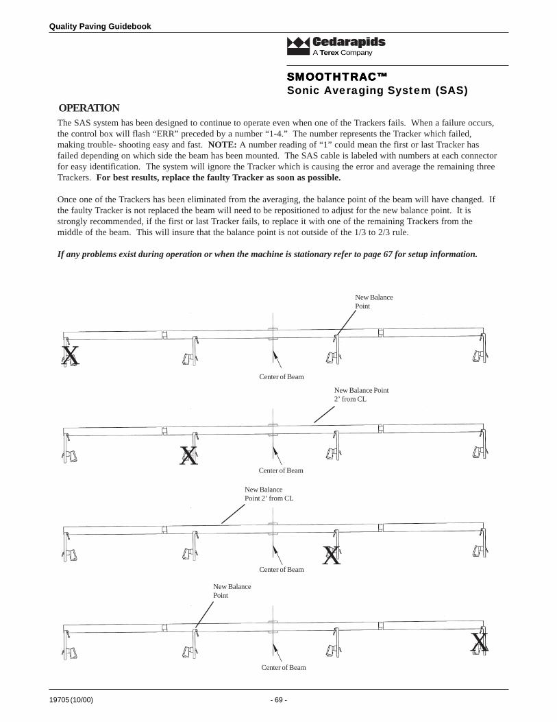
19705 (10/00) - 69 -
Quality Paving Guidebook
A Terex Company
The SAS system has been designed to continue to operate even when one of the Trackers fails. When a failure occurs,the control box will flash “ERR” preceded by a number “1-4.” The number represents the Tracker which failed,making trouble- shooting easy and fast. NOTE: A number reading of “1” could mean the first or last Tracker hasfailed depending on which side the beam has been mounted. The SAS cable is labeled with numbers at each connectorfor easy identification. The system will ignore the Tracker which is causing the error and average the remaining threeTrackers. For best results, replace the faulty Tracker as soon as possible.
Once one of the Trackers has been eliminated from the averaging, the balance point of the beam will have changed. Ifthe faulty Tracker is not replaced the beam will need to be repositioned to adjust for the new balance point. It isstrongly recommended, if the first or last Tracker fails, to replace it with one of the remaining Trackers from themiddle of the beam. This will insure that the balance point is not outside of the 1/3 to 2/3 rule.
If any problems exist during operation or when the machine is stationary refer to page 67 for setup information.
OPERATION
X
X
X
X
New BalancePoint
New BalancePoint
New Balance Point2’ from CL
New BalancePoint 2’ from CL
Center of Beam
Center of Beam
Center of Beam
Center of Beam
SMOOTHTRAC™SMOOTHTRAC™SMOOTHTRAC™SMOOTHTRAC™SMOOTHTRAC™Sonic Averaging System (SAS)

Quality Paving Guidebook
19705 (10/00) - 70 -
A Terex Company
Figure 118
elbaTnoisrevnoCepolS
epolS
lautcAlamicedrephcni
.tf
.xorppAnoitcarfrephcni
.tf
hcnIrep.tf01
hcnIrep.tf11
hcnIrep.tf21
hcnIrep.tf31
hcnIrep.tf41
hcnIrep.tf51
hcnIrep.tf61
hcnIrep.tf71
hcnIrep.tf81
hcnIrep.tf91
hcnIrep.tf02
%01.0 210. 46/1 8/1 8/1 23/5 23/5 23/5 61/3 61/3 23/7 23/7 23/7 4/1
%31.0 510. 46/1 23/5 23/5 61/3 61/3 23/7 23/7 4/1 4/1 23/9 23/9 61/5
%02.0 420. 23/1 4/1 4/1 23/9 61/5 23/11 8/3 8/3 23/31 61/7 23/51 23/51
%62.0 130. 23/1 61/5 23/11 8/3 23/31 61/7 23/51 2/1 23/71 61/9 23/91 8/5
%03.0 630. 46/3 8/3 23/31 61/7 23/51 2/1 23/71 61/9 8/5 23/12 61/11 23/32
%04.0 840. 46/3 2/1 23/71 61/9 8/5 61/11 23/32 23/52 61/31 8/7 23/92 23/13
%05.0 060. 61/1 23/91 23/12 23/32 23/52 23/72 23/92 23/13 23/1-1 23/3-1 8/1-1 61/3-1
%25.0 260. 61/1 8/5 61/11 4/3 61/31 8/7 61/51 1 61/1-1 8/1-1 61/5-1 4/1-1
%06.0 270. 46/5 23/32 23/52 8/7 61/51 1 23/3-1 23/5-1 23/7-1 23/9-1 8/3-1 61/7-1
%87.0 390. 23/3 61/51 23/1-1 8/1-1 23/7-1 61/5-1 23/31-1 2/1-1 23/91-1 61/11-1 23/52-1 8/7-1
%08.0 690. 23/3 23/13 61/1-1 23/5-1 4/1-1 23/11-1 61/7-1 23/71-1 8/5-1 23/32-1 61/31-1 23/92-1
%0.1 021. 8/1 61/3-1 61/5-1 61/7-1 61/9-1 61/11-1 61/31-1 23/92-1 23/1-2 23/5-2 23/9-2 23/31-2
%5.1 081. 61/3 61/31-1 23/12-1 23/5-2 23/11-2 23/71-2 61/11-2 8/7-2 61/1-3 4/1-3 23/31-3 23/91-3
%2 042. 4/1 61/7-2 8/5-2 8/7-2 8/1-3 8/3-3 23/91-3 23/72-3 23/3-4 61/5-4 61/9-4 61/31-4
%3 063. 8/3 8/5-3 23/13-3 61/5-4 61/11-4 23/1-5 23/31-5 4/3-5 8/1-6 23/51-6 23/72-6 61/3-6
%4 084. 23/51 61/31-4 61/9-5 4/3-5 4/1-6 23/32-6 61/3-7 61/11-7 23/5-8 8/5-8 8/1-9 23/91-9
%5 006. 23/91 6 23/91-6 61/3-7 61/31-7 23/31-8 9 23/91-9 61/3-01 61/31-01 23/31-11 21
%6 027. 23/32 61/3-7 23/92-7 8/5-8 8/3-9 23/3-01 61/31-01 23/71-11 4/1-21 23/13-21 61/11-31 23/31-41
%7 048. 23/72 23/31-8 4/1-9 23/3-01 23/92-01 4/3-11 23/91-21 61/7-31 23/9-41 8/1-51 23/12-51 61/31-61
%8 069. 23/23 23/91-9 61/9-01 23/71-11 23/51-21 61/7-31 23/31-41 8/3-51 61/5-61 23/9-71 4/1-81 61/3-91
%9 80.1 23/3-1 61/31-01 8/7-11 23/13-21 23/1-41 8/1-51 61/3-61 23/9-71 8/3-81 23/7-91 23/71-02 23/91-12
%01 02.1 61/3-1 21 61/3-31 23/31-41 23/91-51 61/31-61 81 61/3-91 23/31-02 23/91-12 61/31-22 42
%11 23.1 61/5-1 61/3-31 23/71-41 23/72-51 23/5-71 23/51-81 61/31-91 8/1-12 61/7-22 4/3-32 23/3-52 23/31-62
%21 44.1 61/7-1 23/31-41 23/72-51 23/9-71 23/32-81 23/5-02 23/91-12 23/1-32 23/51-42 23/92-52 8/3-72 61/31-82
.yllatnozirohderusaemerateefniserugifllA.hcni23/1nihtiwotyletaruccadnayllacitrevderusaemebdluohssehcniniserugifllA
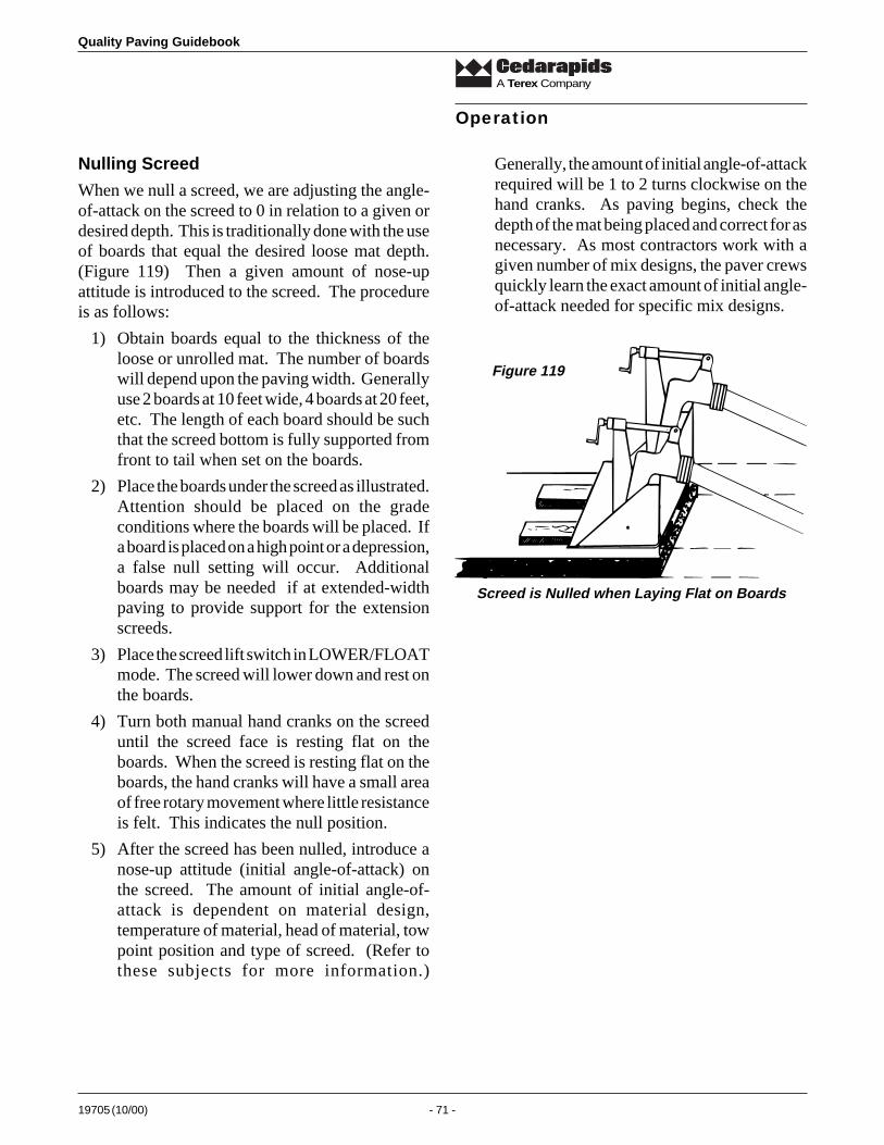
19705 (10/00) - 71 -
Quality Paving Guidebook
A Terex Company
Nulling Screed
When we null a screed, we are adjusting the angle-of-attack on the screed to 0 in relation to a given ordesired depth. This is traditionally done with the useof boards that equal the desired loose mat depth.(Figure 119) Then a given amount of nose-upattitude is introduced to the screed. The procedureis as follows:
1) Obtain boards equal to the thickness of theloose or unrolled mat. The number of boardswill depend upon the paving width. Generallyuse 2 boards at 10 feet wide, 4 boards at 20 feet,etc. The length of each board should be suchthat the screed bottom is fully supported fromfront to tail when set on the boards.
2) Place the boards under the screed as illustrated.Attention should be placed on the gradeconditions where the boards will be placed. Ifa board is placed on a high point or a depression,a false null setting will occur. Additionalboards may be needed if at extended-widthpaving to provide support for the extensionscreeds.
3) Place the screed lift switch in LOWER/FLOATmode. The screed will lower down and rest onthe boards.
4) Turn both manual hand cranks on the screeduntil the screed face is resting flat on theboards. When the screed is resting flat on theboards, the hand cranks will have a small areaof free rotary movement where little resistanceis felt. This indicates the null position.
5) After the screed has been nulled, introduce anose-up attitude (initial angle-of-attack) onthe screed. The amount of initial angle-of-attack is dependent on material design,temperature of material, head of material, towpoint position and type of screed. (Refer tothese subjects for more information.)
Generally, the amount of initial angle-of-attackrequired will be 1 to 2 turns clockwise on thehand cranks. As paving begins, check thedepth of the mat being placed and correct for asnecessary. As most contractors work with agiven number of mix designs, the paver crewsquickly learn the exact amount of initial angle-of-attack needed for specific mix designs.
Operation
Screed is Nulled when Laying Flat on Boards
Figure 119
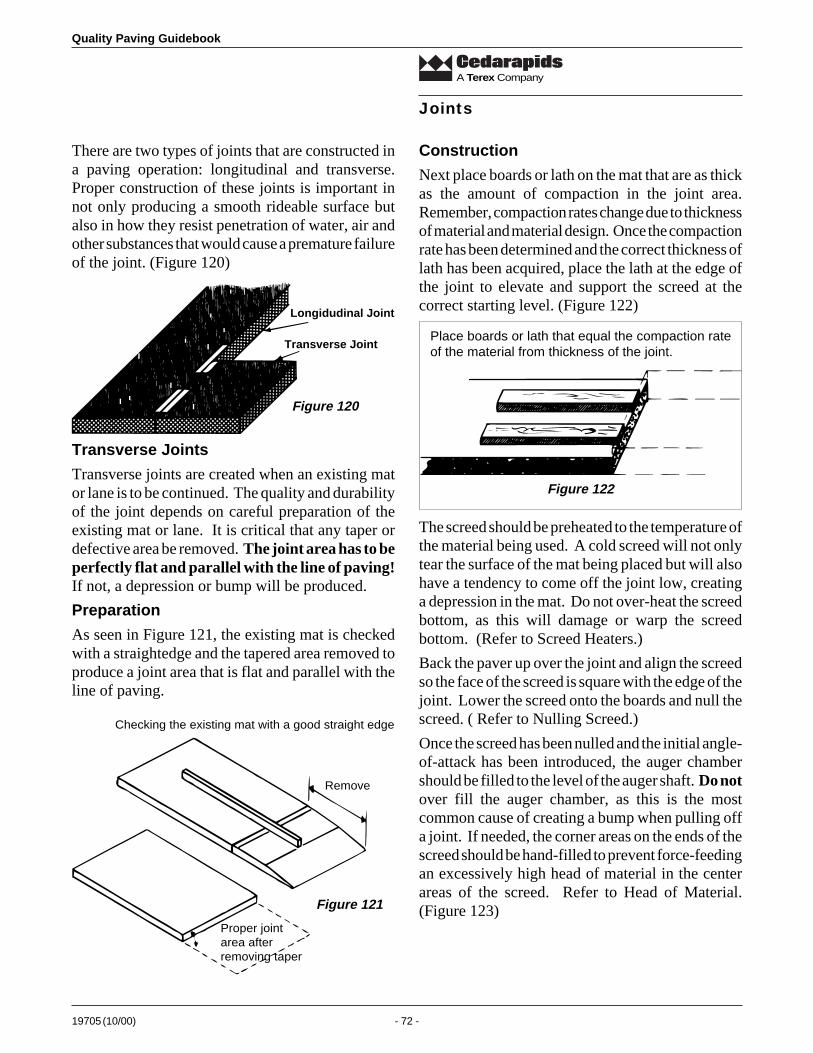
Quality Paving Guidebook
19705 (10/00) - 72 -
A Terex Company
There are two types of joints that are constructed ina paving operation: longitudinal and transverse.Proper construction of these joints is important innot only producing a smooth rideable surface butalso in how they resist penetration of water, air andother substances that would cause a premature failureof the joint. (Figure 120)
Joints
Longidudinal Joint
Transverse Joint
Transverse Joints
Transverse joints are created when an existing mator lane is to be continued. The quality and durabilityof the joint depends on careful preparation of theexisting mat or lane. It is critical that any taper ordefective area be removed. The joint area has to beperfectly flat and parallel with the line of paving!If not, a depression or bump will be produced.
Preparation
As seen in Figure 121, the existing mat is checkedwith a straightedge and the tapered area removed toproduce a joint area that is flat and parallel with theline of paving.
Construction
Next place boards or lath on the mat that are as thickas the amount of compaction in the joint area.Remember, compaction rates change due to thicknessof material and material design. Once the compactionrate has been determined and the correct thickness oflath has been acquired, place the lath at the edge ofthe joint to elevate and support the screed at thecorrect starting level. (Figure 122)
Figure 120
Remove
Proper jointarea afterremoving taper
Checking the existing mat with a good straight edge
Figure 121
Place boards or lath that equal the compaction rateof the material from thickness of the joint.
Figure 122
The screed should be preheated to the temperature ofthe material being used. A cold screed will not onlytear the surface of the mat being placed but will alsohave a tendency to come off the joint low, creatinga depression in the mat. Do not over-heat the screedbottom, as this will damage or warp the screedbottom. (Refer to Screed Heaters.)
Back the paver up over the joint and align the screedso the face of the screed is square with the edge of thejoint. Lower the screed onto the boards and null thescreed. ( Refer to Nulling Screed.)
Once the screed has been nulled and the initial angle-of-attack has been introduced, the auger chambershould be filled to the level of the auger shaft. Do notover fill the auger chamber, as this is the mostcommon cause of creating a bump when pulling offa joint. If needed, the corner areas on the ends of thescreed should be hand-filled to prevent force-feedingan excessively high head of material in the centerareas of the screed. Refer to Head of Material.(Figure 123)
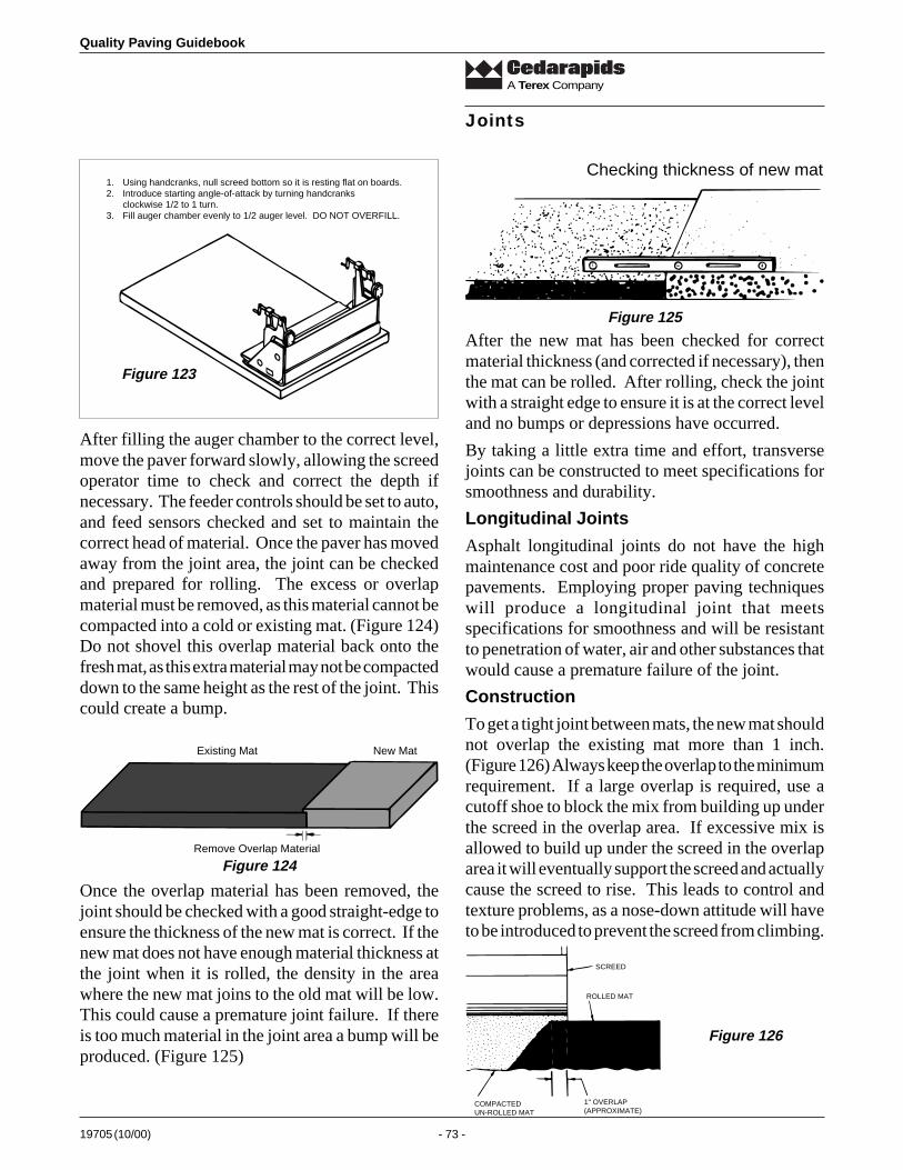
19705 (10/00) - 73 -
Quality Paving Guidebook
A Terex Company
1. Using handcranks, null screed bottom so it is resting flat on boards.2. Introduce starting angle-of-attack by turning handcranks
clockwise 1/2 to 1 turn.3. Fill auger chamber evenly to 1/2 auger level. DO NOT OVERFILL.
Joints
Checking thickness of new mat
Figure 125
After the new mat has been checked for correctmaterial thickness (and corrected if necessary), thenthe mat can be rolled. After rolling, check the jointwith a straight edge to ensure it is at the correct leveland no bumps or depressions have occurred.
By taking a little extra time and effort, transversejoints can be constructed to meet specifications forsmoothness and durability.
Longitudinal Joints
Asphalt longitudinal joints do not have the highmaintenance cost and poor ride quality of concretepavements. Employing proper paving techniqueswill produce a longitudinal joint that meetsspecifications for smoothness and will be resistantto penetration of water, air and other substances thatwould cause a premature failure of the joint.
Construction
To get a tight joint between mats, the new mat shouldnot overlap the existing mat more than 1 inch.(Figure 126) Always keep the overlap to the minimumrequirement. If a large overlap is required, use acutoff shoe to block the mix from building up underthe screed in the overlap area. If excessive mix isallowed to build up under the screed in the overlaparea it will eventually support the screed and actuallycause the screed to rise. This leads to control andtexture problems, as a nose-down attitude will haveto be introduced to prevent the screed from climbing.
COMPACTEDUN-ROLLED MAT
1" OVERLAP(APPROXIMATE)
ROLLED MAT
SCREED
Figure 126
After filling the auger chamber to the correct level,move the paver forward slowly, allowing the screedoperator time to check and correct the depth ifnecessary. The feeder controls should be set to auto,and feed sensors checked and set to maintain thecorrect head of material. Once the paver has movedaway from the joint area, the joint can be checkedand prepared for rolling. The excess or overlapmaterial must be removed, as this material cannot becompacted into a cold or existing mat. (Figure 124)Do not shovel this overlap material back onto thefresh mat, as this extra material may not be compacteddown to the same height as the rest of the joint. Thiscould create a bump.
Figure 123
Existing Mat New Mat
Remove Overlap Material
Figure 124
Once the overlap material has been removed, thejoint should be checked with a good straight-edge toensure the thickness of the new mat is correct. If thenew mat does not have enough material thickness atthe joint when it is rolled, the density in the areawhere the new mat joins to the old mat will be low.This could cause a premature joint failure. If thereis too much material in the joint area a bump will beproduced. (Figure 125)
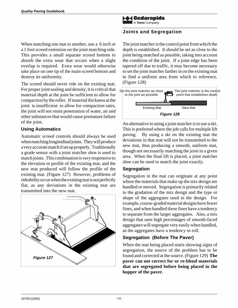
Quality Paving Guidebook
19705 (10/00) - 74 -
A Terex Company
When matching one mat to another, use a 6 inch ora 1 foot screed extension on the joint matching side.This provides a small separate screed bottom toabsorb the extra wear that occurs when a slightoverlap is required. Extra wear would otherwisetake place on one tip of the main screed bottom anddestroy its uniformity.
The screed should never ride on the existing mat.For proper joint sealing and density, it is critical thatmaterial depth at the joint be sufficient to allow forcompaction by the roller. If material thickness at thejoint is insufficient to allow for compaction rates,the joint will not resist penetration of water, air andother substances that would cause premature failureof the joint.
Using Automatics
Automatic screed controls should always be usedwhen matching longitudinal joints. They will producea very accurate match if set up properly. Traditionallya grade sensor with a joint matcher shoe is used tomatch joints. This combination is very responsive tothe elevation or profile of the existing mat, and thenew mat produced will follow the profile of theexisting mat. (Figure 127) However, problems ofrideability occur when the existing mat is not perfectlyflat, as any deviations in the existing mat aretransmitted into the new mat.
The joint matcher is the control point from which thedepth is established. It should be set as close to thejoint being matched as possible, taking into accountthe condition of the joint. If a joint edge has beentapered off due to traffic, it may become necessaryto set the joint matcher farther in on the existing matto find a uniform area from which to reference.(Figure 128)
Joints and Segregation
Figure 127
Set the joint matcher as closeto the joint as possible
The joint matcher is the controlpoint that establishes depth.
Existing Mat New Mat
Figure 128
An alternative to using a joint matcher is to use a ski.This is preferred where the job calls for multiple liftpaving. By using a ski on the existing mat thedeviations in that mat will not be transmitted to thenew mat, thus producing a smooth, uniform mat,though not necessarily matching the joint in a givenarea. When the final lift is placed, a joint matchershoe can be used to match the joint exactly.
Segregation
Segregation in the mat can originate at any pointwhere the materials that make up the mix design arehandled or moved. Segregation is primarily relatedto the gradation of the mix design and the type orshape of the aggregates used in the design. Forexample, course-graded material designs have fewerfines, and when handled these fines have a tendencyto separate from the larger aggregates. Also, a mixdesign that uses high percentages of smooth-facedaggregates will segregate very easily when handled,as the aggregates have a tendency to roll.
Segregation (Before The Paver)
When the mat being placed starts showing signs ofsegregation, the source of the problem has to befound and corrected at the source. (Figure 129) Thepaver can not correct for or re-blend materialsthat are segregated before being placed in thehopper of the paver.
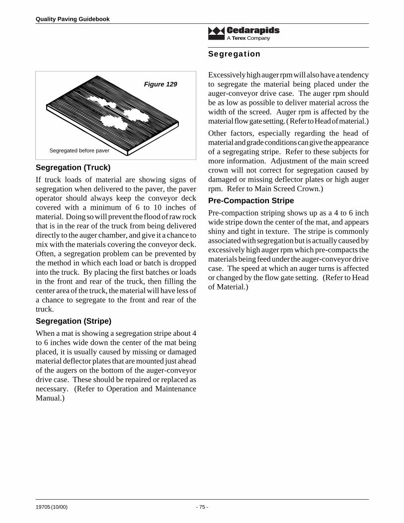
19705 (10/00) - 75 -
Quality Paving Guidebook
A Terex Company
Segregation
Excessively high auger rpm will also have a tendencyto segregate the material being placed under theauger-conveyor drive case. The auger rpm shouldbe as low as possible to deliver material across thewidth of the screed. Auger rpm is affected by thematerial flow gate setting. ( Refer to Head of material.)
Other factors, especially regarding the head ofmaterial and grade conditions can give the appearanceof a segregating stripe. Refer to these subjects formore information. Adjustment of the main screedcrown will not correct for segregation caused bydamaged or missing deflector plates or high augerrpm. Refer to Main Screed Crown.)
Pre-Compaction Stripe
Pre-compaction striping shows up as a 4 to 6 inchwide stripe down the center of the mat, and appearsshiny and tight in texture. The stripe is commonlyassociated with segregation but is actually caused byexcessively high auger rpm which pre-compacts thematerials being feed under the auger-conveyor drivecase. The speed at which an auger turns is affectedor changed by the flow gate setting. (Refer to Headof Material.)
Segregated before paver
Figure 129
Segregation (Truck)
If truck loads of material are showing signs ofsegregation when delivered to the paver, the paveroperator should always keep the conveyor deckcovered with a minimum of 6 to 10 inches ofmaterial. Doing so will prevent the flood of raw rockthat is in the rear of the truck from being delivereddirectly to the auger chamber, and give it a chance tomix with the materials covering the conveyor deck.Often, a segregation problem can be prevented bythe method in which each load or batch is droppedinto the truck. By placing the first batches or loadsin the front and rear of the truck, then filling thecenter area of the truck, the material will have less ofa chance to segregate to the front and rear of thetruck.
Segregation (Stripe)
When a mat is showing a segregation stripe about 4to 6 inches wide down the center of the mat beingplaced, it is usually caused by missing or damagedmaterial deflector plates that are mounted just aheadof the augers on the bottom of the auger-conveyordrive case. These should be repaired or replaced asnecessary. (Refer to Operation and MaintenanceManual.)
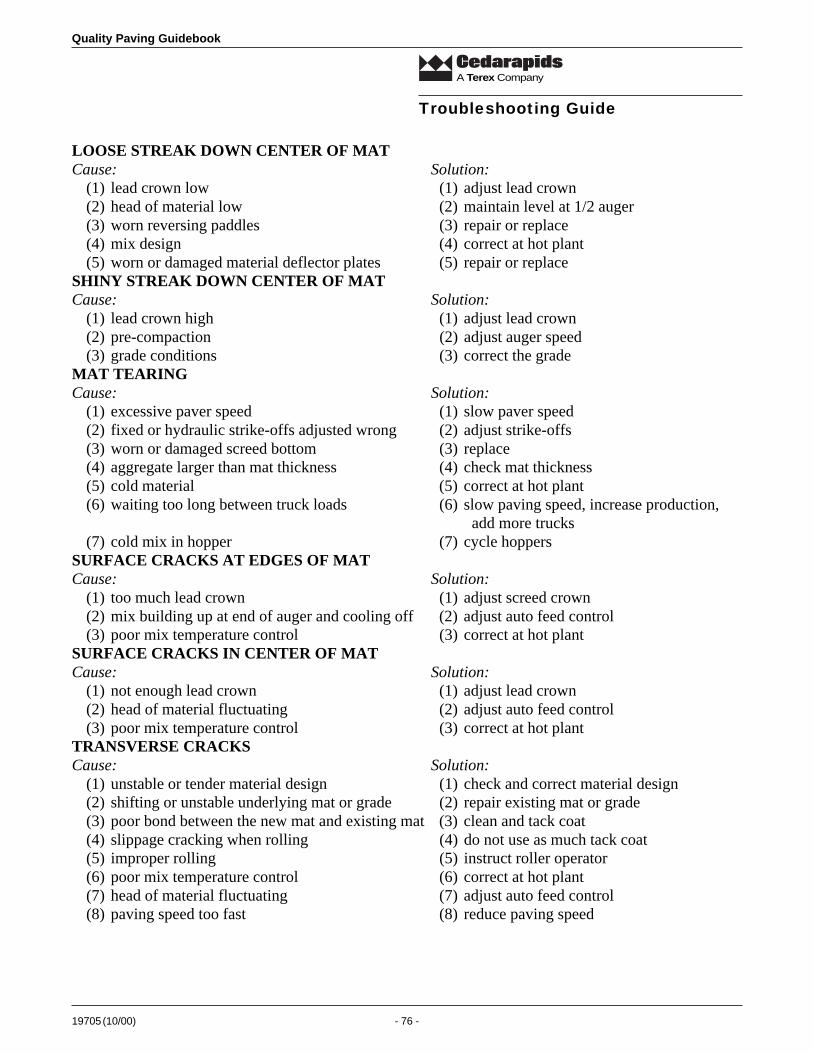
Quality Paving Guidebook
19705 (10/00) - 76 -
A Terex Company
LOOSE STREAK DOWN CENTER OF MATCause: Solution:
(1) lead crown low (1) adjust lead crown(2) head of material low (2) maintain level at 1/2 auger(3) worn reversing paddles (3) repair or replace(4) mix design (4) correct at hot plant(5) worn or damaged material deflector plates (5) repair or replace
SHINY STREAK DOWN CENTER OF MATCause: Solution:
(1) lead crown high (1) adjust lead crown(2) pre-compaction (2) adjust auger speed(3) grade conditions (3) correct the grade
MAT TEARINGCause: Solution:
(1) excessive paver speed (1) slow paver speed(2) fixed or hydraulic strike-offs adjusted wrong (2) adjust strike-offs(3) worn or damaged screed bottom (3) replace(4) aggregate larger than mat thickness (4) check mat thickness(5) cold material (5) correct at hot plant(6) waiting too long between truck loads (6) slow paving speed, increase production,
add more trucks(7) cold mix in hopper (7) cycle hoppers
SURFACE CRACKS AT EDGES OF MATCause: Solution:
(1) too much lead crown (1) adjust screed crown(2) mix building up at end of auger and cooling off (2) adjust auto feed control(3) poor mix temperature control (3) correct at hot plant
SURFACE CRACKS IN CENTER OF MATCause: Solution:
(1) not enough lead crown (1) adjust lead crown(2) head of material fluctuating (2) adjust auto feed control(3) poor mix temperature control (3) correct at hot plant
TRANSVERSE CRACKSCause: Solution:
(1) unstable or tender material design (1) check and correct material design(2) shifting or unstable underlying mat or grade (2) repair existing mat or grade(3) poor bond between the new mat and existing mat (3) clean and tack coat(4) slippage cracking when rolling (4) do not use as much tack coat(5) improper rolling (5) instruct roller operator(6) poor mix temperature control (6) correct at hot plant(7) head of material fluctuating (7) adjust auto feed control(8) paving speed too fast (8) reduce paving speed
Troubleshooting Guide

19705 (10/00) - 77 -
Quality Paving Guidebook
A Terex Company
POOR MAT TEXTURECause: Solution:
(1) tow point too high or low for mat thickness (1) adjust tow point(2) changing mix design or temperature (2) correct at hot plant(3) aggregate larger than mat thickness (3) check mat thickness(4) rolling too much (4) instruct roller operator(5) not using water on roller drums or tires (5) instruct roller operator(6) screed vibration or amplitude wrong for mix (6) instruct screedman(7) fixed or hydraulic strike-offs too high or low (7) adjust strike-offs
MAT SCUFFINGCause: Solution:
(1) full width scuff - cold screed bottom (1) heat screed(2) outer edges scuffing - cold mix at end of augers (2) add auger extensions(3) screed extensions mounted incorrectly (3) adjust
SURFACE TEXTURE FLUCTUATINGCause: Solution:
(1) material design changing (1) correct at hot plant(2) material temperature changing (2) correct at hot plant(3) poor or changing asphalt quality (3) contact distributor(4) aggregate size too large for mat thickness (4) increase mat thickness(5) segregation of material (5) find and correct source(6) too much hand raking or walking on loose mat (6) do not walk on mat - use proper paving
techniques(7) worn or damaged screed (7) repair or replace
BLISTERINGCause: Solution:
(1) moisture in underlying mat or grade (1) allow existing mat or grade to dry out(2) moisture in material (2) correct at hot plant
BROWN STREAKED SURFACECause: Solution:
(1) poor asphalt cement quality (1) contact distributor(2) gas or oil spilled on material (2) find cause and correct
BLEEDINGCause: Solution:
(1) excessive moisture in mix (1) correct at hot plant(2) excessive vibration (2) correct at roller(3) tack coat too heavy (3) use less tack coat(4) too much asphalt in mix (4) correct at hot plant(5) oil or fuel spilled on mat (5) find source and correct
SETTLING MARKS WHEN STOPPEDCause: Solution:
(1) tow point position too high or low for (1) adjust tow point position paving depth
(2) stopping too long (2) adjust paving speed to keep paver moving(3) screed assist not adjusted (3) adjust screed assist system
Troubleshooting Guide

Quality Paving Guidebook
19705 (10/00) - 78 -
A Terex Company
Troubleshooting Guide
BUMPSCause: Solution:
(1) trucks hitting paver (1) instruct driver(2) fluctuating head of material (2) correct head of material(3) erratic stops and starts (3) instruct operator(4) trucks holding brakes (4) instruct driver(5) roller stopping on hot mat (5) instruct operator(6) worn or damaged screed components (6) repair or replace(7) wrong roll pattern (7) instruct operator(8) roller vibrating in place (8) instruct operator(9) grade and/or slope dead band too tight (9) adjust dead band
(10) incorrect mounting of ski or grade sensor (10) mount correctly(11) stringline loose (11) correct stringline(12) overcorrecting hand cranks or automation (12) instruct screedman
RIPPLESCause: Solution:
(1) over-correcting hand cranks or automation (1) instruct screedman(2) worn or damaged screed components (2) repair or replace(3) fluctuating head of material (3) correct head of material(4) variation of mix temperature (4) correct at plant(5) excessive rolling speed (5) instruct operator(6) worn augers (6) repair or replace(7) erratic changes in paving speed (7) instruct operator
RIPPLES (Continued)Cause: Solution:
(8) trucks holding brakes (8) instruct driver(9) rollers on mat too soon (9) instruct operator
(10) rollers in bad repair (10) repairMAT PROFILE INCORRECTCause: Solution:
(1) worn or damaged screed (1) repair or replace(2) grade sensor location incorrect for application (2) move to correct location(3) grade or slope dead band incorrect (3) adjust dead band(4) rolling pattern wrong (4) instruct operator(5) uneven tire pressure (5) adjust tire pressure(6) fluctuating head of material (6) correct head of material(7) varying paving speed (7) maintain same paving speed
POOR JOINT MATCHINGCause: Solution:
(1) overcorrecting hand cranks or automation (1) instruct screedman(2) delay in rolling (2) instruct operator(3) fluctuating head of material (3) correct head of material(4) too much overlap (4) instruct operator(5) grade sensor location incorrect (5) relocate(6) grade sensor dead band incorrect (6) adjust dead band

19705 (10/00) - 79 -
Quality Paving Guidebook
A Terex Company
POOR TRANSVERSE JOINTCause: Solution:
(1) fluctuating head of material (1) correct head of material(2) incorrect joint preparation (2) instruct crew(3) cold screed (3) heat screed(4) incorrect setup of screed (4) instruct screedman(5) poor rolling operation (5) instruct operator
SEGREGATION AT BEGINNING OF NEW TRUCK LOADCause: Solution:
(1) mix segregating while being hauled (1) load truck differently(2) mix segregating in hopper (2) adjust hopper cycling
SEGREGATION AT VARYING POINTS IN MATCause: Solution:
(1) mix segregating at hot plant (1) correct at hot plant(2) mix design varying (2) correct at hot plant
SEGREGATION STRIPE IN CENTER OF SCREEDCause: Solution:
(1) worn reversing paddles (1) repair(2) cold mix buildup between screed face and (2) correct head of material
auger drive case(3) lead crown low (3) adjust lead crown up(4) fixed or hydraulic strike-offs adjusted wrong. (4) adjust strike-offs
INDENTS OR DEPRESSIONS IN ROLLED SURFACECause: Solution:
(1) rolling too much (1) instruct operator(2) not finish-rolling properly (2) instruct operator(3) reversing or turning roller too quickly (3) instruct operator(4) stopping roller on hot mat (4) instruct operator(5) roller in bad repair (5) repair(6) rolling mat when mix temperature is too hot (6) instruct operator(7) irregular grade being paved (7) correct grade before paving(8) unstable or tender mix design (8) correct mix design
SHOVING OF MAT BY ROLLERCause: Solution:
(1) reversing or turning roller too quickly (1) instruct operator(2) rolling mat when mix temperature is too hot (2) instruct operator(3) excessive high asphalt content (3) correct at hot plant(4) tire pressure too high (4) adjust tire pressure(5) unstable or tender mix design (5) correct at hot plant(6) tack coat too heavy (6) use less tack coat(7) material temperature too high (7) correct at hot plant
Troubleshooting Guide

Quality Paving Guidebook
19705 (10/00) - 80 -
A Terex Company
UNSATISFACTORY COMPACTIONCause: Solution:
(1) rolling too fast (1) instruct operator(2) rolling too light (2) increase ballast, change rollers(3) inadequate rolling or not enough rollers (3) change roll patterns or add rollers(4) rolling when material is too cold (4) move roller closer to paver(5) material out of specification (5) correct at hot plant(6) material temperature too hot or cold (6) correct at hot plant
Troubleshooting Guide
19705 (10/00) - 81 -
Quality Paving Guidebook
A Terex Company
Paving Terminology
Aggregate: Various sizes of stones, gravel, pebblesand sand, that comprise the bulk of the material usedin asphalt mixes.
Angle-of-Attack: The angle at which the screedbottom travels through the asphalt material.
Asphalt: The blend of aggregates, fines and asphaltcement.
Auger: The spiral components mounted to the rearof the conveyor discharge that spread the asphaltmaterial evenly across the width of the screed.
Asphalt Cement: A thick petroleum-based productused to bond the aggregates and fines together.
Auger Chamber: The area in which the augers aremounted.
Automatic Feeder Controls: The controls mountedto the outboard end of the augers that control thelevel of material.
Automatic Grade and Slope Controls: Theelectronic grade and/or slope sensory system thatcontrols the angle-of-attack on the screed.
Averaging: The ability of the screed to correct for adeviation over a long travel distance.
Balance: Refers to the equilibrium of forces andfactors that affect the screed’s position.
Compaction: Process of removing the air voids inthe material after placement.
Conveyor: The chain and flight bar arrangement oneach side of the paver that moves material from thehopper to the augers.
Conveyor Deck Liners: The Ni-hard plates orheavy steel plates used to absorb the wear that occursin the bottom of the conveyor area.
Cross Beam: The steel bar connected between theleft and right tow arms which is used for mountingthe slope sensor.
Crown: The ability to change the transverse profileof the mat being placed. Also refers to thetransverse profile or the opposite sloping sides of theexisting grade.
Cutoff Shoe: The detachable plate that fits underthe end gates to reduce the paving width of thescreed.
Density: The degree to which air voids have beenremoved from a material.
Depth Crank: The mechanical adjusting cranklocated on each side of the screed used for setting orchanging the angle-of-attack on the screed.
Deviation: A change in elevation or slope inreference to a given point or plane.
Elevation: The vertical height measured from areference point or plane.
Equilibrium: Refers to the balance of forces andfactors that affect the position or elevation of thescreed.
Fastach Screed: A standard 8 ft. or 10 ft. fixedwidth screed.
Feeders: The left or right auger-conveyorcombination that moves material from the hopperand across the width of the screed.
Flow Gates: The vertical adjustable plates locatedat the rear of the hopper that control the amount orvolume of material that passes from the hopper to theauger chamber.
Frame Raise: (A) The ability of a rubber-tire paverto raise or lower the position of the frame and augers.(B) The ability of the rear drive tires to move up ordown independently of the other.
Grade: (A) Refers to the surface over which pavingis to be done. (B) Refers to the longitudinal angleof rise or fall of the roadway. (C) Refers to theelevation of the roadway.
Grade Control: The electronic system forcontrolling the longitudinal elevation of the matfrom a given reference.
Grade Sensor: The electronic sensor unit used forcontrolling the longitudinal elevation of the mat
Head of material: The given volume and level ofmaterial in front of and across the width of thescreed.
Hydraulic Strike-off: The extendable blade orscreeding blade mounted to the front of a standardscreed.
Joint: The area where two mats meet or join.
Quality Paving Guidebook
19705 (10/00) - 82 -
A Terex Company
Joint Matcher: The grade sensor and skate assemblycombination used to match the elevation of an existingmat or curb.
Lift: Refers to a single layer or mat of a multiple-layered road or refers to the thickness of a specificmat.
Mat: Asphalt materials placed by the paver.
Null or Nulled: (A) Refers to the screed when theface of the screed bottom is resting flat on a surfacewith no angle-of-attack. (B) Refers to the automaticscreed controls when they are in a position where noelectrical signal is being sent or when the indicatorlights are out.
Pre-Leveling: Correction of existing grade or slopedeviations before paving is done.
Pre-Strike-Off: The vertical blades mounted to theface screed, used as a material metering device.
Profile: Refers to the quick changes that occur in theelevation or slope of a mat with the automationsensors mounted in certain positions.
Rideability: Refers to the delayed changes inelevation that occur with the automation sensorsmounted in certain positions.
Ripples: Frequent or close changes in elevation ofthe new mat.
Screed: The unit that is towed behind the tractor thatshapes, smooths and controls the depth of the materialbeing placed.
Screed Assist: A hydraulic control system thatpermits adjusting the weight of a hydraulicallyextendable screed to match material design andpaving width.
Screed Bottom: The replaceable plate that contacts,smooths and compacts the material.
Screed Extensions: The extra attachment used toextend the paving width of a screed.
Screed Heaters: The diesel-fired heaters that pre-heat the screed bottom to the temperature of thematerial being used.
Segregation: The separation of the aggregates fromthe finer materials.
Ski: The floating reference towed beside the screedor tractor that provides a uniform reference for thegrade sensor when building rideability.
Slope: Refers to the transverse angle of the grade orroadway.
Slope Control: The electronic system that controlsthe transverse angle of the mat being placed inreference to the horizon.
Slope Sensor: The electronic unit that detects thetransverse angle of the beam it is mounted on.
Stretch 20 Screed: A 10 ft. to 20 ft. hydraulicallyextendable screed.
String Line: A fixed reference system that utilizespins, rods, or bars and a string line and is establishedalong one or both sides of the intended area to bepaved.
Tow Point: The point from which the screed isattached and towed forward by the tractor.
Tow Point Cylinder: The hydraulic cylinders thatraise or lower the tow point position.
Vibrators: The shaft, eccentric weight and motorcombination that produces a vibrating action in thescreed when rotated.
Paving Terminology
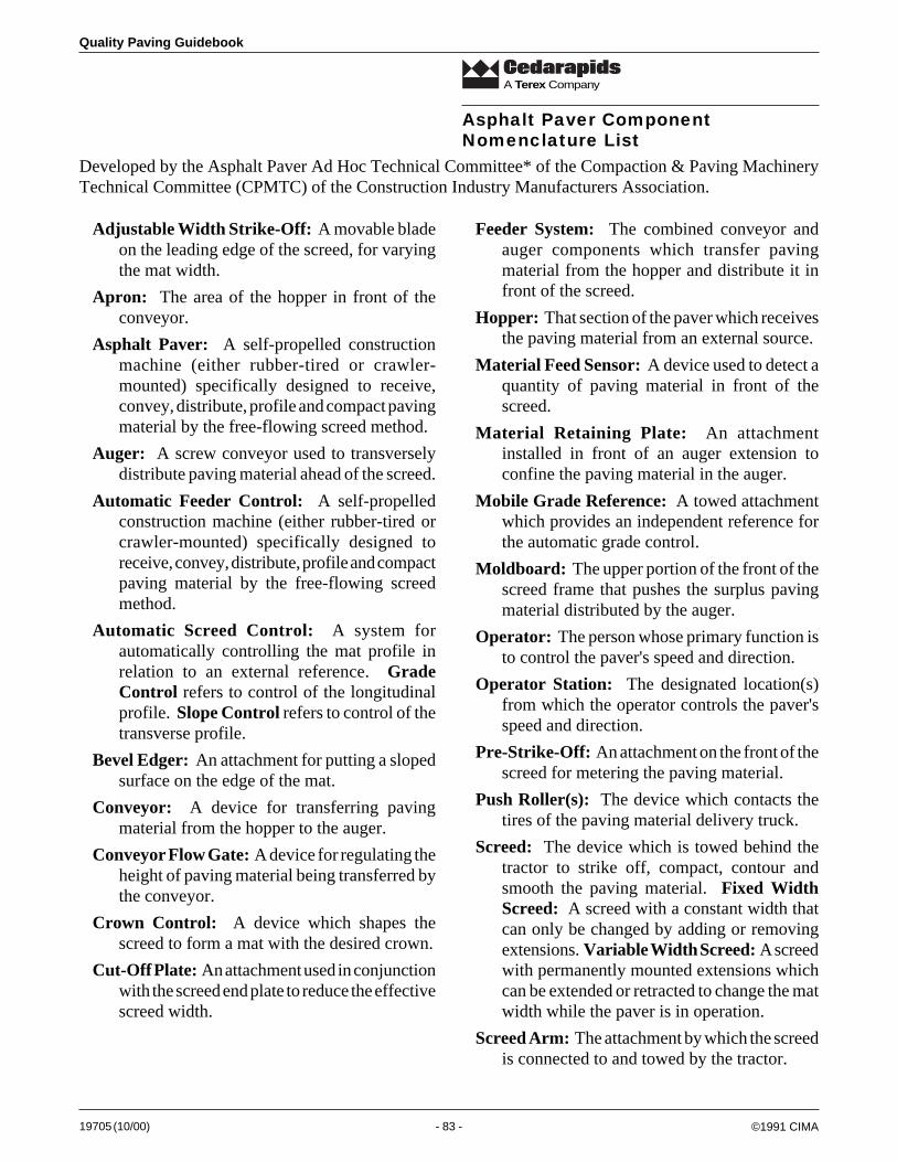
19705 (10/00) - 83 -
Quality Paving Guidebook
A Terex Company
Developed by the Asphalt Paver Ad Hoc Technical Committee* of the Compaction & Paving MachineryTechnical Committee (CPMTC) of the Construction Industry Manufacturers Association.
Adjustable Width Strike-Off: A movable bladeon the leading edge of the screed, for varyingthe mat width.
Apron: The area of the hopper in front of theconveyor.
Asphalt Paver: A self-propelled constructionmachine (either rubber-tired or crawler-mounted) specifically designed to receive,convey, distribute, profile and compact pavingmaterial by the free-flowing screed method.
Auger: A screw conveyor used to transverselydistribute paving material ahead of the screed.
Automatic Feeder Control: A self-propelledconstruction machine (either rubber-tired orcrawler-mounted) specifically designed toreceive, convey, distribute, profile and compactpaving material by the free-flowing screedmethod.
Automatic Screed Control: A system forautomatically controlling the mat profile inrelation to an external reference. GradeControl refers to control of the longitudinalprofile. Slope Control refers to control of thetransverse profile.
Bevel Edger: An attachment for putting a slopedsurface on the edge of the mat.
Conveyor: A device for transferring pavingmaterial from the hopper to the auger.
Conveyor Flow Gate: A device for regulating theheight of paving material being transferred bythe conveyor.
Crown Control: A device which shapes thescreed to form a mat with the desired crown.
Cut-Off Plate: An attachment used in conjunctionwith the screed end plate to reduce the effectivescreed width.
Feeder System: The combined conveyor andauger components which transfer pavingmaterial from the hopper and distribute it infront of the screed.
Hopper: That section of the paver which receivesthe paving material from an external source.
Material Feed Sensor: A device used to detect aquantity of paving material in front of thescreed.
Material Retaining Plate: An attachmentinstalled in front of an auger extension toconfine the paving material in the auger.
Mobile Grade Reference: A towed attachmentwhich provides an independent reference forthe automatic grade control.
Moldboard: The upper portion of the front of thescreed frame that pushes the surplus pavingmaterial distributed by the auger.
Operator: The person whose primary function isto control the paver's speed and direction.
Operator Station: The designated location(s)from which the operator controls the paver'sspeed and direction.
Pre-Strike-Off: An attachment on the front of thescreed for metering the paving material.
Push Roller(s): The device which contacts thetires of the paving material delivery truck.
Screed: The device which is towed behind thetractor to strike off, compact, contour andsmooth the paving material. Fixed WidthScreed: A screed with a constant width thatcan only be changed by adding or removingextensions. Variable Width Screed: A screedwith permanently mounted extensions whichcan be extended or retracted to change the matwidth while the paver is in operation.
Screed Arm: The attachment by which the screedis connected to and towed by the tractor.
Asphalt Paver ComponentNomenclature List
©1991 CIMA
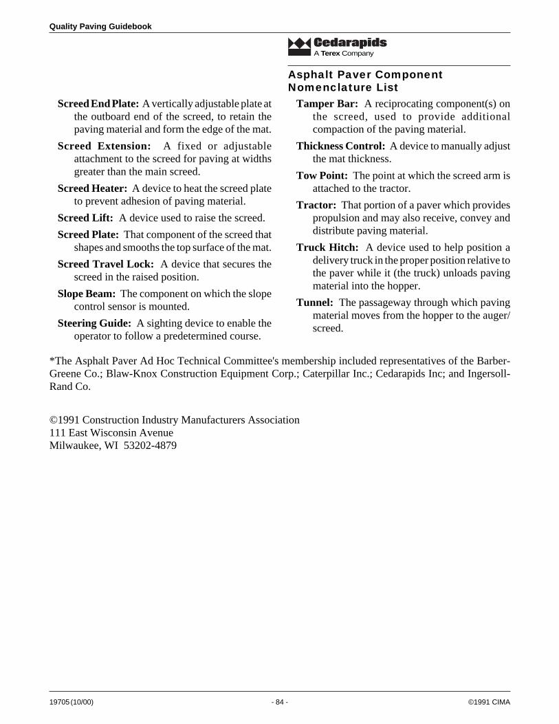
Quality Paving Guidebook
19705 (10/00) - 84 -
A Terex Company
Screed End Plate: A vertically adjustable plate atthe outboard end of the screed, to retain thepaving material and form the edge of the mat.
Screed Extension: A fixed or adjustableattachment to the screed for paving at widthsgreater than the main screed.
Screed Heater: A device to heat the screed plateto prevent adhesion of paving material.
Screed Lift: A device used to raise the screed.
Screed Plate: That component of the screed thatshapes and smooths the top surface of the mat.
Screed Travel Lock: A device that secures thescreed in the raised position.
Slope Beam: The component on which the slopecontrol sensor is mounted.
Steering Guide: A sighting device to enable theoperator to follow a predetermined course.
Tamper Bar: A reciprocating component(s) onthe screed, used to provide additionalcompaction of the paving material.
Thickness Control: A device to manually adjustthe mat thickness.
Tow Point: The point at which the screed arm isattached to the tractor.
Tractor: That portion of a paver which providespropulsion and may also receive, convey anddistribute paving material.
Truck Hitch: A device used to help position adelivery truck in the proper position relative tothe paver while it (the truck) unloads pavingmaterial into the hopper.
Tunnel: The passageway through which pavingmaterial moves from the hopper to the auger/screed.
*The Asphalt Paver Ad Hoc Technical Committee's membership included representatives of the Barber-Greene Co.; Blaw-Knox Construction Equipment Corp.; Caterpillar Inc.; Cedarapids Inc; and Ingersoll-Rand Co.
©1991 Construction Industry Manufacturers Association111 East Wisconsin AvenueMilwaukee, WI 53202-4879
Asphalt Paver ComponentNomenclature List
©1991 CIMA

19705 (10/00) - 85 -
Quality Paving Guidebook
A Terex Company
Rubber-Tire Asphalt Paverwith Fixed-Width Screed
Ho
pp
er
Ap
ron
Mo
bile
Gra
de
Ref
eren
ce
To
w P
oin
t
Gra
de
Co
ntr
ol
Scr
eed
Arm
Mat
eria
l Fee
d S
enso
r
Scr
eed
Pla
teC
row
n C
on
tro
l
Scr
eed
Hea
ter
Slo
pe
Co
ntr
ol
Scr
eed
Tra
vel L
ock
Slo
pe
Bea
m
Op
erat
or
Sta
tio
n
Th
ickn
ess
Co
ntr
ol
Scr
eed
Lif
t
©1991 CIMA
Fig
ure
130
CIM
A
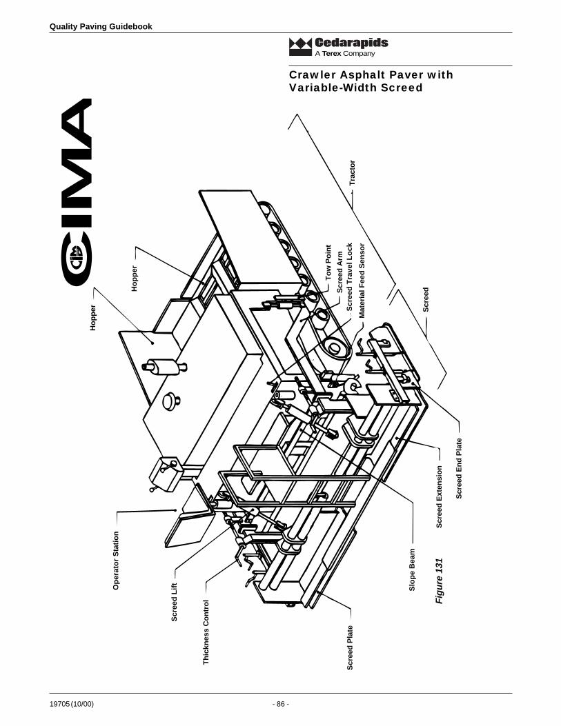
Quality Paving Guidebook
19705 (10/00) - 86 -
A Terex Company
Crawler Asphalt Paver withVariable-Width Screed
Ho
pp
er
Ho
pp
er
Op
erat
or
Sta
tio
n
Scr
eed
Lif
t
Th
ickn
ess
Co
ntr
ol
Scr
eed
Pla
te
Slo
pe
Bea
m
Scr
eed
Ext
ensi
on
Scr
eed
En
d P
late
Mat
eria
l Fee
d S
enso
r
Scr
eed
Scr
eed
Tra
vel L
ock
Scr
eed
Arm
To
w P
oin
t
Tra
cto
r
Fig
ure
131
CIM
A
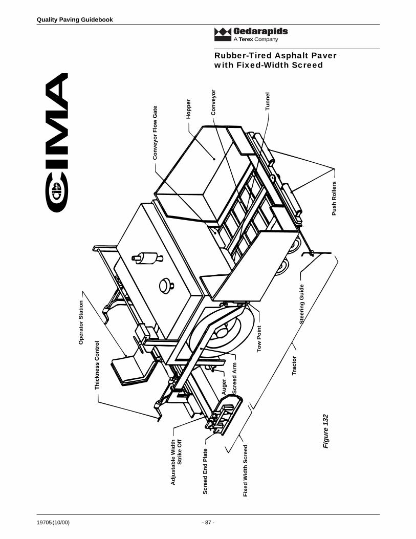
19705 (10/00) - 87 -
Quality Paving Guidebook
A Terex Company
Rubber-Tired Asphalt Paverwith Fixed-Width Screed
Co
nve
yor
Flo
w G
ate
Ho
pp
er
Co
nve
yor
Tu
nn
el
Pu
sh R
olle
rs
Ste
erin
g G
uid
e
To
w P
oin
t
Scr
eed
Arm
Tra
cto
r
Fix
ed W
idth
Scr
eed
Ad
just
able
Wid
thS
trik
e O
ff
Scr
eed
En
d P
late
Op
erat
or
Sta
tio
n
Th
ickn
ess
Co
ntr
ol
Au
ger
Fig
ure
132
CIM
A

Quality Paving Guidebook
19705 (10/00) - 88 -
A Terex Company
Crawler Asphalt Paver withFixed-Width Screed
Scr
eed
Lif
t
Op
erat
or
Sta
tio
n
Th
ickn
ess
Co
ntr
ol
Mo
ld B
oar
d
Scr
eed
En
d P
late
Bev
el E
dg
er
Pre
-Str
ike-
Off
Au
ger
Mat
eria
l Ret
ain
ing
Pla
te
Ste
erin
g G
uid
e
Fix
ed S
cree
dE
xten
sio
n
Scr
eed
Arm
To
w P
oin
t
Co
nve
yor
Flo
w G
ate
Co
nve
yor
Ho
pp
er
Pu
sh R
olle
rs
Tru
ck H
itch
Cu
t-O
ff P
late
Fig
ure
133
CIM
A
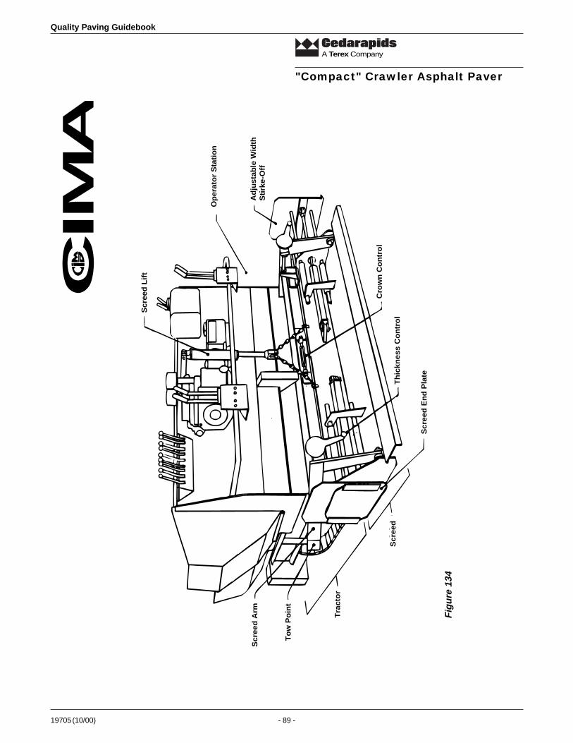
19705 (10/00) - 89 -
Quality Paving Guidebook
A Terex Company
"Compact" Crawler Asphalt Paver
Op
erat
or
Sta
tio
n
Ad
just
able
Wid
thS
tirk
e-O
ff
Scr
eed
Lif
t
Cro
wn
Co
ntr
ol
Th
ickn
ess
Co
ntr
ol
Scr
eed
En
d P
late
Scr
eed
Scr
eed
Arm
To
w P
oin
t
Tra
cto
r
Fig
ure
134
CIM
A

Quality Paving Guidebook
19705 (10/00) - 90 -
A Terex Company