a study of micro-cracks in overheated forgings of ultra ... · a study of micro-cracks in...
TRANSCRIPT
A Study of Micro-cracks in Overheated Forgings of Ultra-Low Sulfur Steels for Aircraft Engine Crankshafts
by
JOHN M. BARSOM President, Barsom Consulting Ltd
Pittsburgh, Pennsylvania
Keywords: Aircraft crankshafts, Low sulfur steel, Overheat, Micro-cracks, Fracture
Abstract
Several crankshafts of aircraft engines fractured in service. Consequently, the present investigation of twenty two (22) broken and recalled crankshafts was conducted. The investigation included hundreds of metallurgical evaluations, numerous fatigue and fracture tests to determine the cause of the failures. The crankshafts were forged from AMS 6414H (AISI 4340) vacuum arc remelted steels with ultra-low sulfur content of less than 0.001%. The investigation revealed that the crankshafts broke because small cracks created in the forging process became large when the crankshafts were subjected to expected operating loads in aircraft engines. The small cracks were caused by incipient melting overheat at grain boundaries. These cracks continued to grow as the engine accumulated more operating time until they reached a critical size causing a sudden failure.
�����������
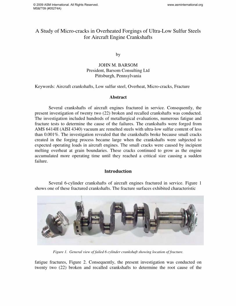
Several 6-cylinder crankshafts of aircraft engines fractured in service. Figure 1 shows one of these fractured crankshafts. The fracture surfaces exhibited characteristic
Figure 1. General view of failed 6 cylinder crankshaft showing location of fracture.
fatigue fractures, Figure 2. Consequently, the present investigation was conducted on twenty two (22) broken and recalled crankshafts to determine the root cause of the
© 2009 ASM International. All Rights Reserved. MS&T'09 (#05274A)
www.asminternational.org

failures. The investigation included hundreds of metallurgical evaluations, numerous fatigue and fracture tests to determine the cause of the failures. fatigue initiation sites
Figure 2. Close up of fatigue fracture showing presence of multiple subsurface initiation sites.
The crankshafts for aircraft engines were forged from about 4 1/2 × 4 1/2 - inch billets of desulfurized, deoxidized and vacuum arc remelted AMS 6414H (AISI/SAE 4340) steel. The billets were expected to be heated and forged into crankshaft configuration at temperatures that conform with industry standards then cooled to ambient temperature. Subsequently, the forged components were to be normalized, austenitized, quenched and tempered, and nitrided. The Forging Industry standard pre-heat temperature for AMS 6414 (AISI 4340) steel is from 1,77oC (2,150oF) to 1,288oC (2,350oF).
The chemical compositions conform to the requirements for 4340 steel modified to contain maximum 0.10 percent vanadium. The sulfur content of the 4340 VAR steel was 0.001 % or less. The hardness of the 4340 VAR crankshaft steel ranged from 32.7 to 35.8 HRc which correspond to tensile strengths between about 148 and 160 ksi.
The crankshaft consists of six crankpin journals, four main bearing journals and an integral flange to which the propeller is attached, Figure 1. Each of the crank pins has a bearing surface that is subjected to piston combustion loads through a connecting rod. Two dynamic counterweights that are located on the rear long cheek of the crankshaft control torsional vibration and therefore control torsion stresses. A gear at the rear of the shaft drives the camshaft and most accessories. The combustion forces applied by the pistons cause the crankshaft to twist and bend. Under these applied loads and crankshaft geometry, the stresses are higher at the fillet radii than in the body of the cheeks or journals. Multi-modal finite element analyses and experimental measurements [1] demonstrated that the highest stresses in the crankshaft under operating conditions occur at the fillets on either side of Cheek 8 at crankpins 5 and 6. Fracture of the crankshafts initiated subsurface just below the nitride layer at these high stress locations
© 2009 ASM International. All Rights Reserved. MS&T'09 (#05274A)
www.asminternational.org
Test Procedures
The present investigation included metallographic and fractographic analyses [2], optical, scanning-electron and Auger-electron microscopy [2, 3], tension-tension fatigue tests [4], and Charpy V-notch fracture tests [5].
The early stages of damage caused by improper forging procedures produces a few small widely dispersed grain boundary defects. The probability of intersecting and exposing one of these defects on a metallographic cross section is remote. Consequently, the use of etched metallographic cross sections to reveal grain boundary defects is usually extremely difficult. Despite these difficulties, the presence of grain boundary cracking in a 6-cylinder crankshaft was accomplished by multiple metallographic preparations of cross sections from a damaged crankshaft.
The best tests to expose the presence of grain boundary damage are the impact notched specimen and the tension-tension fatigue specimen. These test specimens were used in the present investigation. Impact Notched Specimens
Fracture of an impact Charpy V-notched (CVN) specimen produces a single fracture plane that initiates at the tip of the notch and propagates across the specimen cross section. The grain boundary defects that may be exposed on the fracture surface are those that are either along or within the immediate vicinity of the fracture plane. Therefore, this test samples a small volume of material within the test specimen.
Charpy V-notched specimens were machined from the crankshafts. Full size CVN specimens were machined where sufficient material was available; otherwise, specimens of different cross sections and lengths were machined and notched. All notched specimens were tested under fast loading conditions. The tests were conducted at ambient temperatures and at cryogenic temperatures. Fatigue Specimens
Smooth, cylindrical fatigue specimens were machined from the crankshafts. The diameter and length of the specimens were dictated by the available material. The specimens were tested to fracture under tension-tension constant amplitude cyclic loads at a small positive stress ratio, R (ratio of minimum and maximum loads). The tests were conducted at very high stress fluctuation between about 5 and 135 ksi to produce a fatigue fracture and to reveal the fatigue-crack initiating defects rather than to determine the fatigue performance of the crankshafts. However, the characteristics of the fatigue crack initiating defect in combination with the applied stresses can be used to predict the fatigue performance of the crankshafts by using fracture mechanics theory.
© 2009 ASM International. All Rights Reserved. MS&T'09 (#05274A)
www.asminternational.org
Fractographic Analyses
The fracture of impact and notched specimens and of fatigue specimens were studied optically and with SEM. The entire fracture surface of each specimen was scanned 100 percent at different magnifications in the SEM. Auger electron spectroscopy was conducted on representative fracture and fatigue specimens. Metallographic Analyses
Metallographic cross sections from several crankshafts were studied. A few cross sections and an impact fracture surface were etched with a saspananza solution. This etching solution was used to expose the austenite grain boundaries of the quenched and tempered crankshaft steel.
Fracture Test Results Grain Boundary Defects
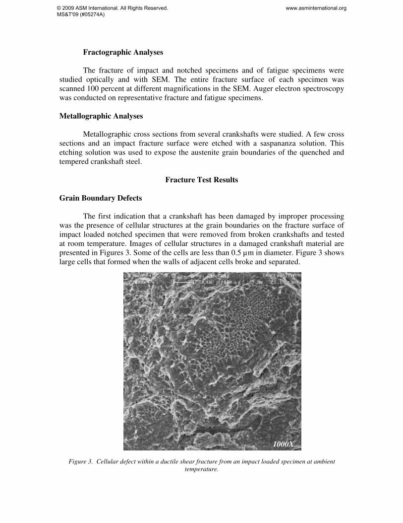
The first indication that a crankshaft has been damaged by improper processing was the presence of cellular structures at the grain boundaries on the fracture surface of impact loaded notched specimen that were removed from broken crankshafts and tested at room temperature. Images of cellular structures in a damaged crankshaft material are presented in Figures 3. Some of the cells are less than 0.5 μm in diameter. Figure 3 shows large cells that formed when the walls of adjacent cells broke and separated.
1000X
Figure 3. Cellular defect within a ductile shear fracture from an impact loaded specimen at ambient temperature.
© 2009 ASM International. All Rights Reserved. MS&T'09 (#05274A)
www.asminternational.org
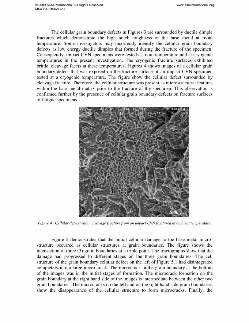
The cellular grain boundary defects in Figures 3 are surrounded by ductile dimple fractures which demonstrate the high notch toughness of the base metal at room temperature. Some investigators may incorrectly identify the cellular grain boundary defects as low energy ductile dimples that formed during the fracture of the specimen. Consequently, impact CVN specimens were tested at room temperature and at cryogenic temperatures in the present investigation. The cryogenic fracture surfaces exhibited brittle, cleavage facets at these temperatures. Figures 4 shows images of a cellular grain boundary defect that was exposed on the fracture surface of an impact CVN specimen tested at a cryogenic temperature. The figure show the cellular defect surrounded by cleavage fracture. Therefore, the cellular structure was present as microstructural features within the base metal matrix prior to the fracture of the specimen. This observation is confirmed further by the presence of cellular grain boundary defects on fracture surfaces of fatigue specimens.
2000X.
Figure 4. Cellular defect within cleavage fracture from an impact CVN fractured at ambient temperature.
Figure 5 demonstrates that the initial cellular damage to the base metal micro-
structure occurred as cellular structures at grain boundaries. The figure shows the intersection of three (3) grain boundaries at a triple point. The fractographs show that the damage had progressed to different stages on the three grain boundaries. The cell structure of the grain boundary cellular defect on the left of Figure 5.1 had disintegrated completely into a large micro crack. The microcrack in the grain boundary at the bottom of the images was in the initial stages of formation. The microcrack formation on the grain boundary at the right hand side of the images is intermediate between the other two grain boundaries. The microcracks on the left and on the right hand side grain boundaries show the disappearance of the cellular structure to form microcracks. Finally, the
© 2009 ASM International. All Rights Reserved. MS&T'09 (#05274A)
www.asminternational.org
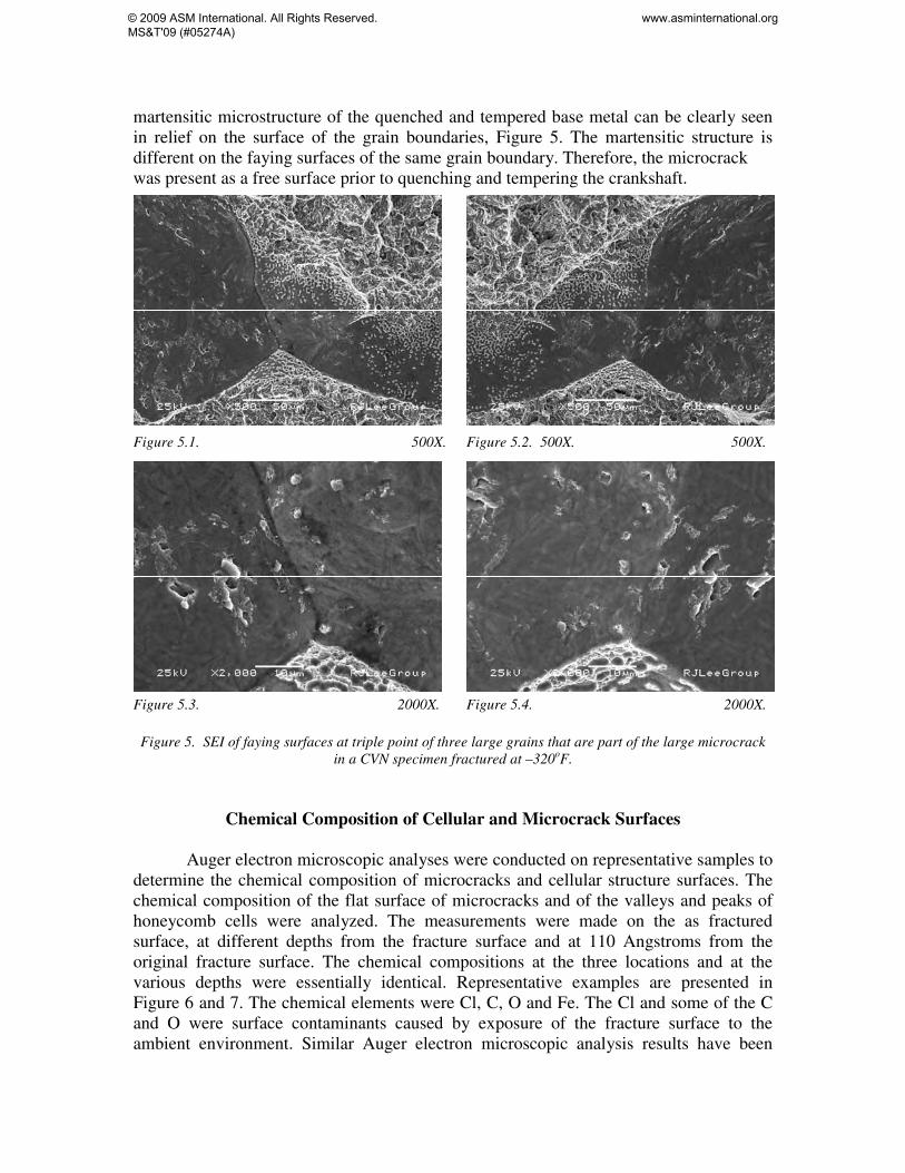
martensitic microstructure of the quenched and tempered base metal can be clearly seen in relief on the surface of the grain boundaries, Figure 5. The martensitic structure is different on the faying surfaces of the same grain boundary. Therefore, the microcrack was present as a free surface prior to quenching and tempering the crankshaft. Figure 5.1. 500X. Figure 5.2. 500X. 500X. Figure 5.3. 2000X. Figure 5.4. 2000X. Figure 5. SEI of faying surfaces at triple point of three large grains that are part of the large microcrack
in a CVN specimen fractured at –320oF.
Chemical Composition of Cellular and Microcrack Surfaces
Auger electron microscopic analyses were conducted on representative samples to determine the chemical composition of microcracks and cellular structure surfaces. The chemical composition of the flat surface of microcracks and of the valleys and peaks of honeycomb cells were analyzed. The measurements were made on the as fractured surface, at different depths from the fracture surface and at 110 Angstroms from the original fracture surface. The chemical compositions at the three locations and at the various depths were essentially identical. Representative examples are presented in Figure 6 and 7. The chemical elements were Cl, C, O and Fe. The Cl and some of the C and O were surface contaminants caused by exposure of the fracture surface to the ambient environment. Similar Auger electron microscopic analysis results have been
© 2009 ASM International. All Rights Reserved. MS&T'09 (#05274A)
www.asminternational.org

documented by Dr. R. W. Hinton on an ultra-low sulfur steel crankshaft [6]. The data demonstrate the absence of any alloy segregation on the damaged grain boundaries.
Figure 6. Auger electron chemical analyses on the fracture surface of Specimen P2.
Figure 7. Auger electron chemical analysis at 110A below the fracture surface.
© 2009 ASM International. All Rights Reserved. MS&T'09 (#05274A)
www.asminternational.org

Size of Microcracks
Figure 8 shows the size of microcracks relative to the grain size of the quenched and tempered steel. The figure presents a microcrack and a photomicrograph of the prior austenite grain size of the quenched and tempered microstructure at the same magnification. The figure shows that the microcrack is several times larger than the size of the prior austenite grain size of the quenched and tempered base metal. Therefore, the microcrack was present as a free surface prior to the quenching and tempering of the base metal. The large size of the microcrack indicates that it was formed when the base metal was at high temperature during forging. 130 μm ASTM GS 2.5 - 3 130 μ 500X. 500X.
Figure 8. Comparison of microcrack size and prior austenite grain size of quenched and tempered crankshaft material.
Microcracks on Metallographic Cross Sections
A longitudinal section through the rear main bearing journal and adjacent cheek
of a broken 6-cylinder crankshaft was ground, polished and etched. A search of the surface revealed the presence of several microcracks. One of these cracks is shown in Figures 9. The length of the cracks should not be assumed to be equal to the maximum size of the crack. They are the edges of the cracks that were exposed by a single slice through the crack plane. Despite this observation, the figure shows that the length of the microcrack is several times longer than the size of the austenite grains of the quenched and tempered 4340 steel. The grain boundaries on either side of the crack are not aligned and the grains formed independently of each other. Therefore, the cracks formed before the crankshaft was austenitized, quenched and tempered. The micrograph shows the presence of cellular grain boundary structure within the microcracks.
© 2009 ASM International. All Rights Reserved. MS&T'09 (#05274A)
www.asminternational.org
2000X.
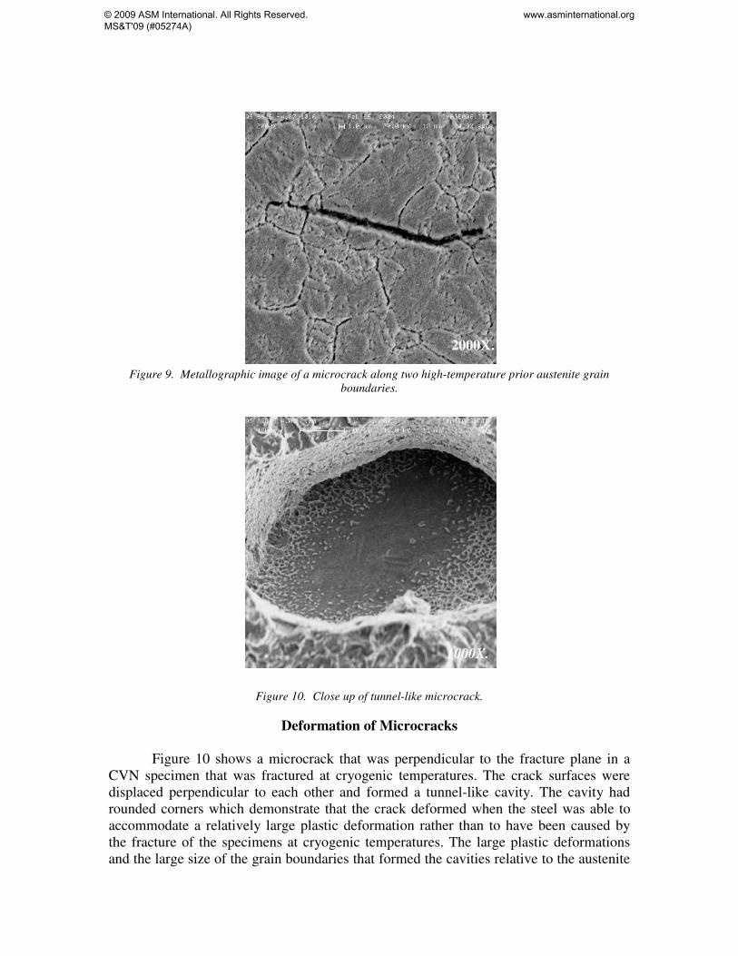
Figure 9. Metallographic image of a microcrack along two high-temperature prior austenite grain boundaries.
1000X.
Figure 10. Close up of tunnel-like microcrack.
Deformation of Microcracks
Figure 10 shows a microcrack that was perpendicular to the fracture plane in a CVN specimen that was fractured at cryogenic temperatures. The crack surfaces were displaced perpendicular to each other and formed a tunnel-like cavity. The cavity had rounded corners which demonstrate that the crack deformed when the steel was able to accommodate a relatively large plastic deformation rather than to have been caused by the fracture of the specimens at cryogenic temperatures. The large plastic deformations and the large size of the grain boundaries that formed the cavities relative to the austenite
© 2009 ASM International. All Rights Reserved. MS&T'09 (#05274A)
www.asminternational.org
grain size of the quenched and tempered steel, demonstrate that the cracks were created when the steel was at high temperatures during forging. Dr. R. W. Hinton demonstrated that these incipient melting defects form in ultra-low sulfur steel crankshafts forged at temperatures of about 1,364oC (2,487oF) or higher [6].
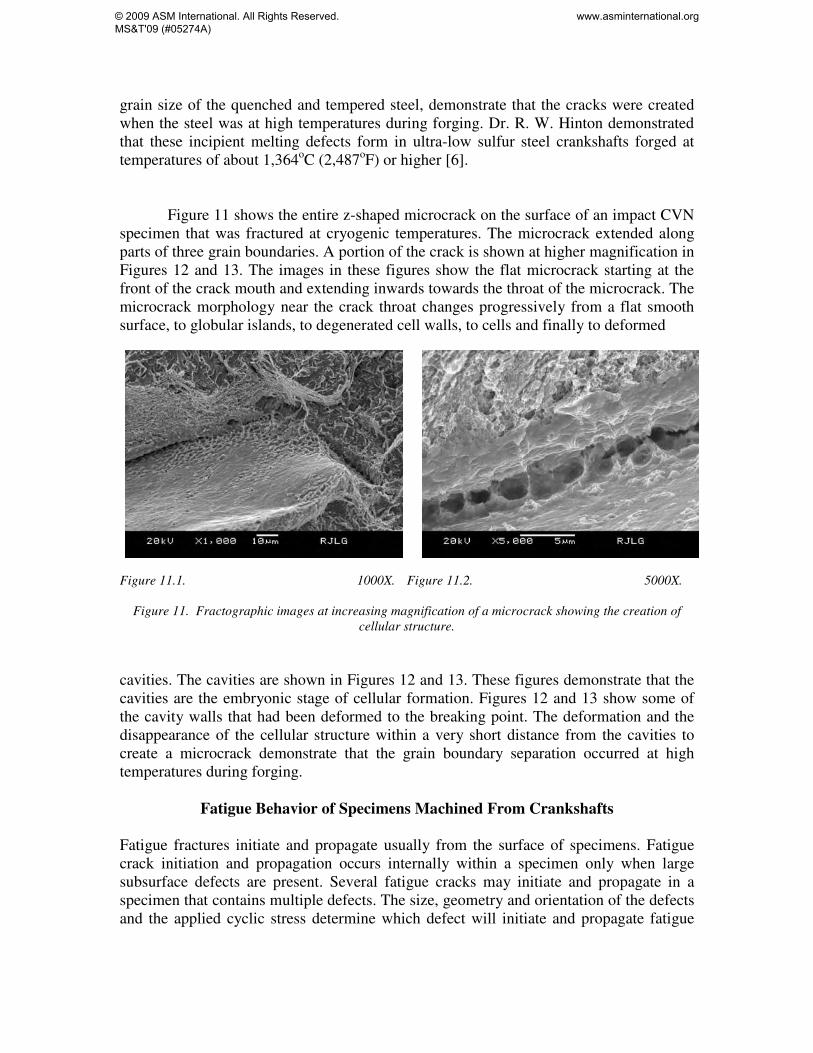
Figure 11 shows the entire z-shaped microcrack on the surface of an impact CVN specimen that was fractured at cryogenic temperatures. The microcrack extended along parts of three grain boundaries. A portion of the crack is shown at higher magnification in Figures 12 and 13. The images in these figures show the flat microcrack starting at the front of the crack mouth and extending inwards towards the throat of the microcrack. The microcrack morphology near the crack throat changes progressively from a flat smooth surface, to globular islands, to degenerated cell walls, to cells and finally to deformed Figure 11.1. 1000X. Figure 11.2. 5000X.
Figure 11. Fractographic images at increasing magnification of a microcrack showing the creation of cellular structure.
cavities. The cavities are shown in Figures 12 and 13. These figures demonstrate that the cavities are the embryonic stage of cellular formation. Figures 12 and 13 show some of the cavity walls that had been deformed to the breaking point. The deformation and the disappearance of the cellular structure within a very short distance from the cavities to create a microcrack demonstrate that the grain boundary separation occurred at high temperatures during forging.
Fatigue Behavior of Specimens Machined From Crankshafts Fatigue fractures initiate and propagate usually from the surface of specimens. Fatigue crack initiation and propagation occurs internally within a specimen only when large subsurface defects are present. Several fatigue cracks may initiate and propagate in a specimen that contains multiple defects. The size, geometry and orientation of the defects and the applied cyclic stress determine which defect will initiate and propagate fatigue
© 2009 ASM International. All Rights Reserved. MS&T'09 (#05274A)
www.asminternational.org

cracks and which defects remain dormant [7]. Fracture of a fatigue specimen that is subjected to tension-tension cyclic loads initiates and propagates from the most severe
21X.
Figure 13. Two fatigue cracks initiating in a smooth cylindrical 4304 crankshaft steel specimen. (a) 1000X. (b) 1000X. Figure 14, Close ups of (a) the primary and (b) the secondary fatigue initiating microcracks in Figure 13. defect that resides within the entire volume of the reduced cross section. Therefore, the test samples a large volume of the material within the specimen. The severity of the defect is a function of its size, geometry and orientation.
Figure 14 shows a primary and a secondary fatigue crack. The primary fatigue crack propagated to critical size. The secondary fatigue crack initiated independently
© 2009 ASM International. All Rights Reserved. MS&T'09 (#05274A)
www.asminternational.org
away from the primary crack. Figure 15 presents close up of the crack initiating sites. They show that the fatigue crack initiating defects for both cracks were microcracks on grain boundaries.
Conclusions The following are a few conclusions that are based on results of the present investigation:
1. Failure analyses demonstrated the presence of cellular structure and microcrack defects on fracture surfaces of fractured crankshafts and of specimens removed from recalled crankshafts.
2. The cellular and microcrack defects were not caused by elemental segregation.
3. The cellular and microcrack defects were caused by incipient melting on grain boundaries.
4. The cellular and microcracks were created during forging the crankshafts at temperatures exceeding industry standards.
5. Forging ultra-low sulfur steels at temperatures above forging industry standards preheat temperatures induces incipient melting defects at grain boundaries that may cause fracture of components under normal operating conditions.
REFERENCES
1. Mark Rumizen, et al., “Lycoming Special Certification Review Team (SCRT)”, Final Report, Federal Aviation Administration, September 30, 2004.
2. Metallography and Microstructures, Metals Handbook, 9th Edition, ASM International, Metal Park, 1985.
3. T. M. Postek, K. S. Howard, A. H. Johnson and K. L. McMichael, Scanning Electron Microscopy – A Students Handbook, Michael T. Postek, Jr. and Ladd Research Industries, Inc., 1980.
4. “Standard Practice for Conducting Force Controlled Constant Amplitude Axial Fatigue Tests of Metallic Materials,” ASTM E 466, Annual Book of ASTM Standards, Volume 03.01, ASTM International, West Conshohocken, 2004.
5. “Standard Test Method for Notched Bar Impact Testing Of Metallic Materials,” ASTM E 23, Annual Book of ASTM Standards, Volume 03.01, ASTM International, West Conshohocken, 2004.
6. R. W. Hinton, “Failure Analyses of Six Cylinder Aircraft Engine Crankshafts,” Case History, Journal of Failure Analysis and Prevention, Issue 6, ASM International, December, 2007.
7. Barsom, J. M. and Rolfe, S. T., Fracture and Fatigue in Structures: Applications of Fracture Mechanics, 3rd Ed. ASTM MNL41, ASTM International, West Conshohocken, 1999.
© 2009 ASM International. All Rights Reserved. MS&T'09 (#05274A)
www.asminternational.org
ASM International is the society for materials engineers and scientists, a worldwide network dedicated to advancing industry, technology, and applications of metals and materials.
ASM International, Materials Park, Ohio, USA www.asminternational.org
This publication is copyright © ASM International®. All rights reserved.
Publication title Product code MS&T’09 CD 05274A
To order products from ASM International:
Online Visit www.asminternational.org/bookstore
Telephone 1-800-336-5152 (US) or 1-440-338-5151 (Outside US)Fax 1-440-338-4634
Mail Customer Service, ASM International 9639 Kinsman Rd, Materials Park, Ohio 44073-0002, USA
Email [email protected]
In Europe
American Technical Publishers Ltd. 27-29 Knowl Piece, Wilbury Way, Hitchin Hertfordshire SG4 0SX, United Kingdom Telephone: 01462 437933 (account holders), 01462 431525 (credit card) www.ameritech.co.uk
In Japan Neutrino Inc. Takahashi Bldg., 44-3 Fuda 1-chome, Chofu-Shi, Tokyo 182 Japan Telephone: 81 (0) 424 84 5550
Terms of Use. This publication is being made available in PDF format as a benefit to members and customers of ASM International. You may download and print a copy of this publication for your personal use only. Other use and distribution is prohibited without the express written permission of ASM International.
No warranties, express or implied, including, without limitation, warranties of merchantability or fitness for a particular purpose, are given in connection with this publication. Although this information is believed to be accurate by ASM, ASM cannot guarantee that favorable results will be obtained from the use of this publication alone. This publication is intended for use by persons having technical skill, at their sole discretion and risk. Since the conditions of product or material use are outside of ASM's control, ASM assumes no liability or obligation in connection with any use of this information. As with any material, evaluation of the material under end-use conditions prior to specification is essential. Therefore, specific testing under actual conditions is recommended.
Nothing contained in this publication shall be construed as a grant of any right of manufacture, sale, use, or reproduction, in connection with any method, process, apparatus, product, composition, or system, whether or not covered by letters patent, copyright, or trademark, and nothing contained in this publication shall be construed as a defense against any alleged infringement of letters patent, copyright, or trademark, or as a defense against liability for such infringement.
© 2009 ASM International. All Rights Reserved. MS&T'09 (#05274A)
www.asminternational.org