a simple fluxgate magnetometer using amorphous alloys
TRANSCRIPT
Journal of Magnetism and Magnetic Materials 103 (1992) 81-85 North-Holland
A simple fluxgate magnetometer using amorphous alloys
S o b h e n d u K. G h a t a k and A m i t a v a Mi t r a
Department of Physics and Meteorology, Indian Institute of Technology, Kharagpur 721302, W.B., India
Received 4 April 1991; in revised form 12 July 1991
A simple fluxgate magnetometer is developed using low magnetostrictive ferromagnetic amorphous alloy acting as a sensing element. It uses the fact that the magnetization of sensing element symmetrically magnetized by a sinusoidal field contains even harmonic components in presence of dc signal field H and the amplitude of the second harmonic component of magnetization is proportional to H. The sensitivity and linearity of the magnetometer with signal field are studied for parallel configuration and the field ranging from 10 nT to 10 ixT can be measured. The functioning of the magnetometer is demonstrated by studying the shielding and flux-trapping phenomena in high-T c superconductor.
I. Introduction
The fluxgate magnetometer is a device that uses the nonlinear field dependence of magneti- zation of a ferromagnetic element which acts as a core material of the fluxgate head. In the absence of signal field which is of low amplitude dc or slowly varying ac, the ferromagnetic core is ex- cited by a harmonic field in such a way that the sensed signal contains only the odd harmonic components of the fundamental excitation fre- quency. In presence of signal field the component of even harmonic appears and in particular, the second harmonic component which is monitored in presence of signal field is sensitively related to the signal field. The detail mechanism of the fluxgate and its different mode of operation have been discussed in the literature [1]. Simplicity, stability, ruggedness, small size and low noise make this type of magnetometer suitable com- pared to other types of vector magnetometers (e.g. Hall effect magnetometer , SQUID, etc.) in the application of different fields like space, geo- magnetic, nondestructive research, etc. [3,4].
Most fluxgate systems use the second har- monic as the signal voltage detected with accom- panying electrons. These systems differ mainly in the construction of sensor configurations of flux-
gate head and the core material [1,2]. The paral- lel-gating sensor configurations consists of ferro- magnetic core (ring or rod-shaped) magnetized by excitation field parallel to signal field and is placed within the senser coil that detects the second harmonic signal. Recently, the ferromag- netic amorphous alloy with low magnetostriction has been used as core material in constructing the fluxgate sensor [5,6]. The Co-based ferromag- netic amorphous ribbon shaped in the form of ring [5] or hairpin [6] constitutes the core which induces signal to a pick-up coil that surrounds the core.
Here we have developed a simple fluxgate magnetometer using low magnetostrictive ferro- magnetic amorphous alloy as its sensing element and the second harmonic as signal voltage. But it differs from the traditional fluxgate magnetome- ter in detecting the signal. The exciting ac current magnetizes simultaneously the sensing core and an auxiliary core in such a fashion that both of them are in zero-flux state. The dc signal field acting on the sensing core disturbs the zero-flux state of it and this in turn produces a net magne- tization in the auxiliary core. This magnetization is detected by a pick-up coil wrapped over the auxiliary core. The auxiliary core due to its large permeability amplifies the signal and acts as a
0304-8853/92/$05.00 © 1992 - Elsevier Science Publishers B.V. All rights reserved
82 S.K. Ghatak, A. Mitra / A simple fluxgate magnetometer
parametric amplifier. This magnetometer is found to be suitable in the medium and high signal field ranging from 10 nT to 10 ~T. The construction and operational principle of the magnetometer has been described in section 2. In section 3.1 the measurement of dc field has been described. As a model demonstrat ion of the working of the mag- netometer, the phenomena of magnetic shielding and flux-trapping in high-T~, superconductor at 77 K is studied (section 3.2).
2. The construction and principle of operation
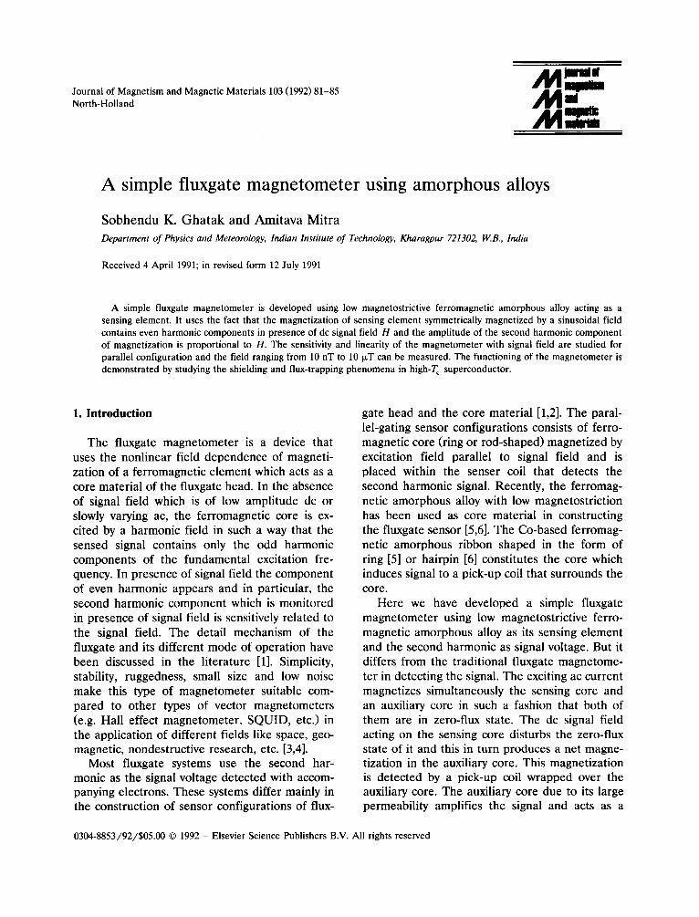
The schematic diagram of the magnetometer together with the measuring system is shown in fig. 1. LI and L 2 are two identical coils having 1500 turns and are wrapped almost over the amorphous ribbons, so they act as a sensing core (M). Three pieces of amorphous low magne- tostrictive (Fea.zCo65.~)70Si]2Bl~ alloy (width 2 mm and thickness 30 ~,m) are used as the core element. Due to low anisotropy energy the mate- rial has high permeability and low Barkhausen noise. The length of M is 4 cm which is larger than the length (1 cm) of the coils Lj and L 2. The coils L 1 and L 2 together with core M constitute the fluxgate head. C is a toroidal t ransformer with low magnetostrictive amorphous material
(Vitroval 6150) as its core. It consists of 20 layers of the sample (Vitroval 6510) in a toroidal shape and heated at 300°C for 1 h to relieve internal stresses and the stress developed due to wrapping into toroidal form. The coils L~ and L~ together with two small coils P~ and P, constitute two identical parallel arms between the ac source and the ground. The ac source generates the driving field that magnetizes the ribbon. In absence of the signal field, which is usually dc or very low frequency ac and is generally a small fraction of the peak value of the driving field, the sensing core (M) is magnetized symmetrically with refer- ence to the sample centre. So the impedances of the two parallel arms (P~, L 2) and (P2, L2) arc identical and the magnetizing current of the transformer (C) is nearly zero resulting in an almost zero signal across the secondary S. In the presence of the signal field, the core is magne- tized asymetrically and signal appears at sec- ondary S due to imbalances of the impedances of the two arms. The core C amplifies the signal due to its ferromagnetic property. The ferrite core having high initial permeability can also be used for this purpose. Due to asymmetrical polariza- tion, the signal voltage contains the even harmon- ics of the fundamental frequency of driving ac field. The amplitude of the output signal (V) at secondary S depends on various factors like the
M
7- I !
L
~L
AC CONSTAkI'[ C UP, RENT $OUROE
-~= I0 ~4 I-1'7.
c
L2
=ILTER TUNED OR / ,AMPLIFIER 2~: =20"KHz OMIM i
Fig. 1. Block d i ag ram of the m a g n e t o m e t e r . L 1 and L 2 are two ident ica l coils, M is the sensing a m o r p h o u s core, Pt and P2 are two small p r imar ies , S is the secondary and C is a toro idal core m a d e from Vi t rovac 6150.
S.K. Ghatak, A. Mitra / A simple fluxgate magnetometer 83
number of turns, value of the inductors etc. and is given as [7]
C U~ ( z ~ - z,) (1)
where Z1, Z e = impedances of the coils L 1, Lz; N,, No= number of turns of secondary (S) and
primary PI or P2 respectively; K = coupling constant between L 1 and L2; L o = inductance of the coil P~ or P2. The coupling between coils L 1 and L 2 is large ( K < 1) due to the presence of the magnetic ribbon, and thus the signal is enhanced due to this particular configuration.
The values of different parameters of the mag- netometer at zero signal field are given in table 1.
The frequency of the driving field is chosen to be 10 kHz so that the resistive load in primary can be neglected which was the basic assumption in deducing the expression (1). The driving field is derived from an ac constant current source. After eliminating the fundamental component from sensed signal V by a notch filter, the second harmonic component of V is amplified by tuned amplifier (overall gain 70). The output of the tuned amplifier (V 0) is measured either by a lock-in amplifier PAR 5209) for a low level signal or by a digital microvoltmeter (Keithley 197).
3. Results and discussions
3.1. D C field measurement
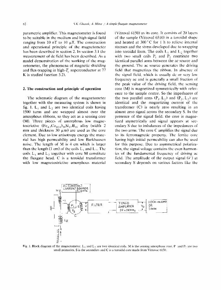
The dc signal field to be measured is produced by long solenoid and is parallel to core axis and also uniform over the core. The response of the magnetometer depends on the excitation current (iex) which generates the driving field and it is shown in fig. 2. The output exhibits a broad maximum around 6.1 mA of excitation current, and the sensitivity decreases for higher excitation current. As the observed sensitivity is highest around iex --- 6.4 mA; all measurements have been performed using this value of the excitation cur- rent. The second harmonic amplitude, V 0 is found
¢ ,~/F I , , I
T ~ z.l.o 6.0 ~,.o
;. cx (mA)
Fig. 2. Variation of sensitivity due to different excitation current (iex) for parallel configuration.
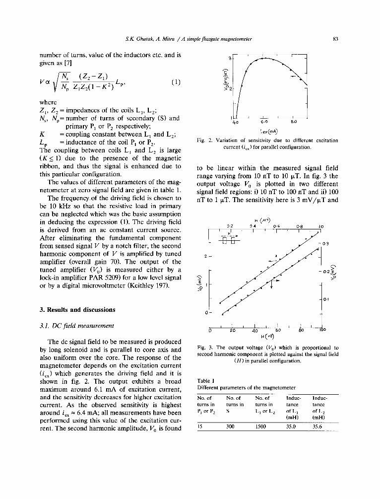
to be linear within the measured signal field range varying from 10 nT to 10 txT. In fig. 3 the output voltage V 0 is plotted in two different signal field regions: i) 10 nT to 100 nT and ii) 100 nT to 1 IxT. The sensitivity here is 3 mV/ ixT and
0.2 04 0.6 0-8 '10 t ___HL_ ' I ' I ' I / '
0-3
2
O.2 L >o
0.t
0
J I i t J 1 i I I O 20 40 60 80 too
.(o~)
Fig. 3. The output voltage (V 0) which is proportional to second harmonic component is plotted against the signal field
( H ) in parallel configuration.
Table 1 Different parameters of the magnetometer
No. of No. of No. of Induc- Induc- turns in turns in turns in tance tance P1 or P2 S L l o r L 2 o f L 1 o f L 2
(mH) (mH)
15 300 1500 35.0 35.6
84 S.K. Ghatak, A. Mitra / A simple fluxgate magnetometer
;~I (a) /
0 U2 0"6 I 0 Cos 0
I I I 10 20 30
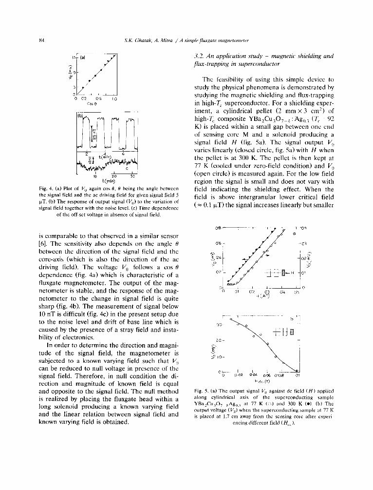
Fig. 4. (a) Plot of V 0 again cos 0, O being the angle between the signal field and the ac driving field for given signal field 5 p.T. (b) The response of output signal (V o) to the variation of signal field together with the noise level. (c) Time dependence
of the off-set voltage in absence of signal field.
3.2. An application study - magnetic shielding and flux-trapping in superconductor
The feasibility of using this simple device to study the physical phenomena is demonstrated by studying the magnetic shielding and flux-trapping in high-T c superconductor. For a shielding exper- iment, a cylindrical pellet (2 mm × 3 cm 2) of high-T c composite YBa2Cu30 7 ~ :Ago. 3 (T c = 92 K) is placed within a small gap between one end of sensing core M and a solenoid producing a signal field H (fig. 5a). The signal output V, varies linearly (closed circle, fig. 5a) with H when the pellet is at 300 K. The pellet is then kept at 77 K (cooled under zero-field condition) and V, (open circle) is measured again. For the low field region the signal is small and does not vary with field indicating the shielding effect. When the field is above intergranular lower critical field ( = 0.1 ~zT) the signal increases linearly but smaller
is comparable to that observed in a similar sensor [6]. The sensitivity also depends on the angle 0 between the direction of the signal field and the core-axis (which is also the direction of the ac driving field). The voltage V 0 follows a cos 0 dependence (fig. 4a) which is characteristic of a fluxgate magnetometer . The output of the mag- netometer is stable, and the response of the mag- netometer to the change in signal field is quite sharp (fig. 4b). The measurement of signal below 10 nT is difficult (fig. 4c) in the present setup due to the noise level and drift of base line which is caused by the presence of a stray field and insta- bility of electronics.
In order to determine the direction and magni- tude of the signal field, the magnetometer is subjected to a known varying field such that V, can be reduced to null voltage in presence of the signal field. Therefore, in null condition the di- rection and magnitude of known field is equal and opposite to the signal field. The null method is realized by placing the fluxgate head within a long solenoid producing a known varying field and the linear relation between signal field and known varying field is obtained.
o'8[' ~ T ~ . r~o '4
>o // />o
,
0 dl (3"2 03 0"4 05 H (~0
r - ¸ , • ,
>°~0k
o l 0 0-02 O.04 0-06 O"08 (3"1
H dc ("r)
Fig. 5. (a) The output signal V~ against dc field (H) applied along cylindrical axis of the superconducting sample YBa2Cu307 aAg0.3 at 77 K (o) and 300 K (*). (b) The output voltage (V 0) when the superconducting sample at 77 K is placed at 1.7 cm away from the sensing core after experi-
encing different field (Hdc).
S.K. Ghatak, A. Mitra / A simple fluxgate magnetometer 85
in magnitude compared to earlier situation. To study the flux-trapping effect the superconduct- ing sample at 77 K (zero-field cooled) is exposed to dc magnetic field (Hdc) before it is placed coaxially at a distance of 1.7 cm from one end of core M. Due to flux-trapping the sample behaves like a magnet, and the signal V 0 is then the measure of the amount of flux trapped within the sample (fig. 5b). The t rapped flux decreases with the increase of Hdc and nearly vanishes around 0.09 T which is a measure of the upper critical field at 77 K.
phenomena in ceramic superconductor using this magnetometer .
Acknowledgements
The work is done with financial assistance from D.S.T., Government of India. We are thankful to Mr. S. Mazumder for technical help and Dr. D. Bhattacharya for providing the super- conducting sample.
4. Conclusion
The fluxgate magnetometer proposed and tested is simple to construct and shows linearity over a wide range of signal field. The signal is sensed differently compared to a traditional flux- gate sensor. Due to the absence of a surrounding secondary and use of small material the miniatur- ization can easily be achieved. The sensor perfor- mance is similar to other fluxgate sensors devel- oped using amorphous material [6]. It is possible to study the magnetic shielding and flux-trapping
References
[1] D.I. Gordon and R.E. Brown, IEEE Trans. Magn. MAG-8 (1972) 76.
[2] F. Primdahl, IEEE Trans. Magn. MAG-6 (1970) 376; J. Phys. 12 (1979) 241.
[3] P.C. Hedgecock, HEOS Satellites Space Sci. Instr. 1 (1975) 61.
[4] S.F. Stuart, Rep. Prog. Phys. 35 (1972) 803. [5] P. Ripka, F. Jires and M. Machacek, IEEE Trans. Magn.
MAG-26 (1990) 2038. [6] O.V. Nielsen, J. Gutierrez, B. Hernando and H.T. Savage,
IEEE Trans. Magn. MAG-26 (1990) 276. [7] A. Mitra and S.K. Ghatak, J. Magn. Magn. Mater. 66
(1987) 361.