a simple, but sensitive magnetometer for use in high magnetic fields
TRANSCRIPT
Physica 107B (1981) 589-590 JF 2 North-Holland Publishing Company
A SIMPLE, BUT SENSITIVE MAGNETOMETER FOR USE IN HIGH MAGNETIC FIELDS
Jos A.A.J. Perenboom*
Physics Laboratory University of N~megen
Nijmegen, The Netherlands
A Simple magnetometer is described which can detect changes in the magnetic moment of a sample as small as 3x10 -9 J/T, in applied magnetic fields up to 8 T. The sensiti- vity for volume-susceptibility, A X = 10 -6 (MKSA), is better than the reported perfor- mance of conventional magnetometers.
INTRODUCTION:
In recent years much progress has been made in exploiting the high sensitivity of superconduc- ting quantum interference devices (SQUID's) to measure the magnetic susceptibility of weakly magnetic materials and of very small magnetic samples. [i] However, the use of a SQUID as a detector leads to many complications in the measurement procedure. At the very high level of sensitivity of the SQUID, Much effort is re- quired to control signals due to the residual (temperature-dependent) susceptibility of the construction materials, and to stabilize the applied magnetic field. Therefore, well-esta- blished techniques as the Faraday method, or vibrating sample magnetometers are still widely used.
The present investigation was mainly stimulated by the fact that attempts in our laboratory to use a vibrating sample magnetometer at the ll- mits of its sensitivity often failed. Despite all the precautions we had taken, this seemed to be due to spurious signals caused by coup- ling of the vibrational energy to the pickup coils, or to parts of the cryostat. The problem can be alleviated by a decrease of the frequency of vibrations, but unless the amplitu- de of the vibration is substantially increased, the sensitivity is lowered, as well. [2]
Therefore, we have chosen a different approach. Our pickup circuit is a low inductance super- conducting coil, and this circuit is coupled to a galvanometer which is less sensitive than a SQUID. In a preliminary study, magnetic moments as small as 10 -8 J/T could be detected. [3] In this paper the performance is reported of a magnetometer constructed around a high field superconductive solenoid and a variable temp- erature cryostat insert. [4]
DESCRIPTION OF THE MAGNETOMETER:
A shielding current will flow in the supercon- ducting circuit, proportional to the magnetic flux applied to the pickup coils, e.g. the flux due to the static applied magnetic field. The simplest way to separate the part of the signal originating in the sample from the large back-
ground is to vary the position of the sample and to detect the resulting change in the out- put of the galvanometer. For this purpose, it is of advantage to use a coil with gradiometer symmetry. This reduces the signal caused by the applied magnetic field. The distance of the two oppositely wound coils is chosen so that the flux sensed varies linearly with the position of the sample, near the center of the coils. In this case, ~he sensitivity is not proportional to the frequency of vibration, but only to the amplitude of the modulation of the position of the sample, and phase sensi- tive detection can be used at a suitably low frequency. Our pickup toll consisted of two one-layer coils, 50 turns each, on a 17.6 mm diameter coil-form which allowed insertion of the tail of a continuous flow cryostat for re- gulation of the sample temperature from 2.5 K to 300 K.
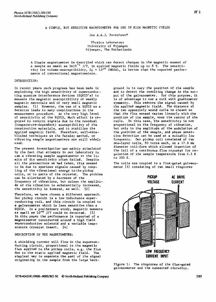
The coils are coupled to a flux-gated galvano- meter [5] consisting of two small ringcores
PICKUP AC DRIVE VOLTAGE CURRENT
! '
ii
LOW FREQUENCY CURRENT INPUT
Figure I: The ringCores of the flux-gated galvanometer and the connected circuitry.
0378-4363/81/0000-0000/$02.50 © North-Holland Publ/shing Company 589
590
with seyeral layers of 0.006 ram thick high per- meability tape. [6] The arrangement of the windings is illustrated in figure i. The two ringcores are driven well into saturation by a 7.5 kHz ~urrent with 180 ° difference in phase. The amplitude of the second harmonic contribu- tion to the induction voltage measured across the two ringcores is proportional to the current flowing in the low frequency input win- dings. Note from figure I that these have been wound around an extra ringcore. [6] As the flux transformer represents a large load to the galvanometer, currents are induced in this cir- cuit that will tend to degrade the performance of the detector. Great care was taken to match the flux-gated galvanometer to the flux trans- former, and it was found that inductive shiel- ding of the pickup circuit from the galvanome- ter proper is most effective. Depending on theself-inductance of the pickup coil and on the amount of magnetic material in the shiel- ding ringcore, an optimum can be found for the number of turns that should couple the signal to the galvanometer. In our case this number was as low as 4. Then, the effective induc- tance of the flux transformer is mainly due to the self-inductance of the pickup coils and is approximately 35 DH. Therefore, the mag- netic shielding may be increased, until the effective inductance of the coupling turns is matched to the inductance of the pickup coils.
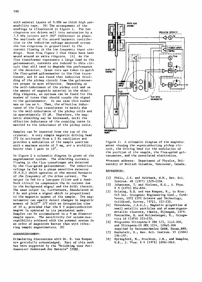
Samples can be inserted from the top of the cryostat. A very simple magnetic driving head [7] is activated from a 2 Hz oscillator and provides a modulation of the sample position with a maximum stroke of 5 mm, and a stability better than I part in l0 s .
In figure 2 a schematic diagram is given of the magnetometer system. The shielding currents flowing in the flux transformer are detected by the flux-gated galvanometer. The induction voltage is fed to a phase sensitive detector (P.S.D.) which operates at the second harmonic of the frequency of the drive current. The output is fed to a low-pass filter and a feed- back circuit to compensate the dc current due to the background signal and the drift therein. The same output is, furthermore, demodulated at 2 Hz and gives a signal which is proportional to the magnetic moment of the sample. The mag- netometer can easily detect changes in magnetic moment of 3x10 -9 J/T with an integration time of 30 s, provided that the 8 T superconductive magnet is operated in its persistent mode. Samples can be accommodated in a 9 mm diameter sample space. The sensitivity for volume-sus- ceptibility achieved with the present system is an order of magnitude better than with vibra- ting sample magnetometers. [8]
ACKNOWLEDGEMENT:
Stimulating discussions with Dr. H. van Kempen are gratefully acknowledged. Part of this work has been supported by the "Stichtlng voor Fun- damenteel Onderzoek der Materie" (FOM).
SAt AS|
SUPE!~mU~IiV[ I, UGNE!
Figure 2: A schematic diagram of the magneto- meter showing the superconducting pickup cir- cuit, the driving head for the modulation of the position of the sample, the flux-gated gal- vanometer, and the associated electronics.
*Present address: Department of Physics, Unl- versity of British Columbia, Vancouver, Canada.
REFERENCES:
[i] Philo, J.S. and Fairbank, W.M., Rev. Sci. Instrum. 48 (1977) 1529-1536.
[2] Johansson, T. and Nielsen, K.G., J. Phys. E 9 (1976) 852-854.
[3] Gelsing, R.R. and van Kempen, H., in Proc. 4th Int. Cryogenic Engineering Conf., Eind- hoven, 1972 (IPC Science and Technology, Guildford, Surrey, 1972), 233-235.
[4] Perenboom, J.A.A.J., Magnetic properties of small metallic particles and of some organo- metallic clusters, thesis, Nijmegen, 1979.
[5] Poerschke, R. and Wollenberger, H., Cryoge- nics i0 (1970) 333-335.
[6] Ringcores Ultraperm-Z ZKK 5/3, llx0.006, and Ultraperm-10 ZKK 12/4, 120x0.006 supplied by Vacuumschmelze GmbH, Hanau,BRD.
[7] Kankeleit, E., Rev. Sci. Instrum. 35 (1964) 194-197.
[8] Springford, M., Stockton, J.R., and Wample~ W.R., J. Phys. E 4 (1971) 1036-1040.