a quick connect vacuum seal
TRANSCRIPT

A Quick Connect Vacuum SealHerbert W. Jones Citation: Review of Scientific Instruments 41, 141 (1970); doi: 10.1063/1.1684252 View online: http://dx.doi.org/10.1063/1.1684252 View Table of Contents: http://scitation.aip.org/content/aip/journal/rsi/41/1?ver=pdfcov Published by the AIP Publishing Articles you may be interested in Sealing mechanisms in bakeable vacuum seals J. Vac. Sci. Technol. A 1, 211 (1983); 10.1116/1.572075 A Bakeable, Quick-Connect High Vacuum Flange J. Vac. Sci. Technol. 9, 1123 (1972); 10.1116/1.1317002 Vacuum Seal Am. J. Phys. 35, iv (1967); 10.1119/1.1974221 Vacuum Seals Rev. Sci. Instrum. 34, 118 (1963); 10.1063/1.1718106 A QuickChange Seal Opener Rev. Sci. Instrum. 24, 886 (1953); 10.1063/1.1770873
This article is copyrighted as indicated in the article. Reuse of AIP content is subject to the terms at: http://scitationnew.aip.org/termsconditions. Downloaded to IP:
132.174.255.116 On: Fri, 28 Nov 2014 12:01:26

NOTES 141
180·
1600
1400
1200
CI
'" 1000 ..J
'" Z <[
w 80· a. 0 '-> VI
60·
40·
20·
180·
FIG. 2. Calibration curve, showing observed and calculated deviations between rotation angles 0 and 0'. The calculations were performed with parameters d = 7.11 mm and d' = 6.35 mm. -0- -Experimental, - - - --calculated.
loop Ll is found by taking the line integral of A around the loop, and is of the form
[Sin2Q' + (cosQ' -d/ d')2]
~=~~ , sin2Q' + (cosQ' +d/ d')2
(2)
where Q' is the angle between the plane of Ll and the plane of the modulation wires, d' is the separation of the wires in the loop, and EO is a constant independent of Q'. The emf in the second pickup loop, which is orthogonal to loop L 1, is calculated from Eq. (2) by using angles Q' + 7r/2. The angle n is given by
(3)
The dashed curve in Fig. 2 shows the result of the calculation. Allowance can be made for the finite length of the modulation wires, but under the present conditions no appreciable change is found. The observed deviation between the experimental and the theoretical curve is due to slight differences in the size and mounting of the pickUp loops.
The goniometer tube was made of hardened polyethylene tubing (6.3 6 mm o.d., 4.32 mm i.d.) fitting the cavity sample ports. The crystal is mounted on a Teflon plug in the tube. Rotation of the goniometer tube was effected by a simple worm and wheel system. The coils Ll and L2 were made of 0.152 mm (38 SWG, British) copper wire inlaid into grooves in the tube, cut at right angles to one another along the length of the tubing exterior, and were held in place by fusion welding. Three gold-plated copper commutator rings were mounted at one end of the goniometer tube. One end of each pickup loop was connected in common to the outer-
most ring 3. The other ends of loops Ll and L2 were connected to the rings 1 and 2, respectively. Three nickelsilver contact rods were mounted on an insulated post attached to the waveguide and carry the signals from the commutator to twin-lead shielded cables connected to the measuring system.
The output voltages from the pickup coils were amplified by a pair of transistor amplifiers and applied to the X and Y inputs of a Phillips oscilloscope (model PM3230). The gains of the two amplifiers were adjusted so that the maximum voltages observed from each loop gave the same deflection. A phase shift network was included to eliminate phase differences between VIand V 2, observable at intermediate angles.
* Work performed in the Physics Department, University of Canterbury, New Zealand and in part at Argonne National Laboratory.
1 D. Corson and P. Lorrain, Electromagnetic Fields and Waves (W. H. Freeman and Co., San Francisco, 1962), p. 189.
A Quick Connect Vacuum. Seal
HERBERT W. JONES
Physics Department, Florida A &1' M University, Tallahassee, Florida 32307
(Received 8 September 1969)
A NEW type fore-vacuum seal has been devised which can be used to quickly connect and disconnect, with
out modification, tubes or components of a given outside diameter. The seal is superior to that of a vacuum hose and is equal to or better than that of standard O-ring construction; furthermore, the components may be rotated without the seal being broken. The principle illustrated here in this device may be of use in the design of various other types of seals and gaskets.
Basically this "balloon" seal is made by forcing air into a chamber which causes a flexible element to expand and close the gap between the two components to be joined. In Fig. 1 the seal employed to connect two 25 mm o.d. pipes is shown. The flexible element is a 45 mm length of 25 rom i.d.X 1.65 mm wall thickness extruded rubber (Viton) tubing; it is secured at both ends by hose clamps (not shown). The device will seal with a gauge pressure of i atm. With a pressure of 3 atm in the chamber the pipe joint may be as much as 7 mm from the center of the seal. For convenience, the pressure hose could be replaced by an inner tube tire valve. Since it appears that there are no critical elements in the seal, its size could be greatly reduced.
This article is copyrighted as indicated in the article. Reuse of AIP content is subject to the terms at: http://scitationnew.aip.org/termsconditions. Downloaded to IP:
132.174.255.116 On: Fri, 28 Nov 2014 12:01:26
142 NOTES
P C
-- -I Jl
1- ------RESSURE ~
HAMBER
!,L
I
FIG. 1. A "balloon" type vacuum seal.
J
The author wishes to acknowledge the assistance of Edward Cohen and to thank B. J. Williams for the drawing.
Power Measurement of Large Laser Beams with a Small Dual-Cone Calorimeter
E. D. WEST AND D. A. JENNINGS
National Bureau of Standards, Boulder, Colorado 80302
(Received 23 September 1969)
M EASUREMENTS of the power or energy in laser beams of large cross section can be made with small
commercially available dual-cone calorimeters! by using sampling techniques, provided the calorimeters are used as intended. The reference cone is intended to compensate for ambient conditions but this cone must obviously be covered for sampling large beams. Since both the reference and input cones sense radiation incident on the front surface of the calorimeter, the method of covering the cone may cause an error in the measurement. Covering the half of the front surface containing the reference cone prevents compensation by this cone for the energy incident on the surface around the input cone. We have investigated the magnitude of the error experimentally. We covered the lower half of the front surface, including the reference cone, and just the opening of the input cone, so as to observe only the effect of radiation incident on the front surface surrounding the input cone. The response to 1.06 J.I. radiation was 3% of the response obtained when the input cone was uncovered. The error for other wavelengths may be different, since the surface may absorb more or less of the incident radiation.
The recommended technique is to provide an aperture which allows a sample of the beam to enter the input cone but prevents the beam from irradiating any part of the front surface of the calorimeter.
1 H. G. Heard, Laser Parameter Measurements Handbook (John Wiley & Sons, Inc., New York, 1968), p. 153.
Simple Teflon-Sealed Thermocouple for High Pressure and Vacuum. Systems
DOMINGO K. L. TAN*
Department of Physics, Rochester Institute of Technology, Rochester, New York 14623
(Received 30 June 1969; and in final form, 22 August 1969)
I N the study of pressure effects on atomic spectral lines, it is desirable to measure the temperature of the gas
medium inside the absorption cell1,2 with a pressure seal thermocouple. The problem is the pressure seal around the fine thermocouple wires. Pressure seal thermocouples are available commercially3 but they restrict the design of the absorption cell to some extent.
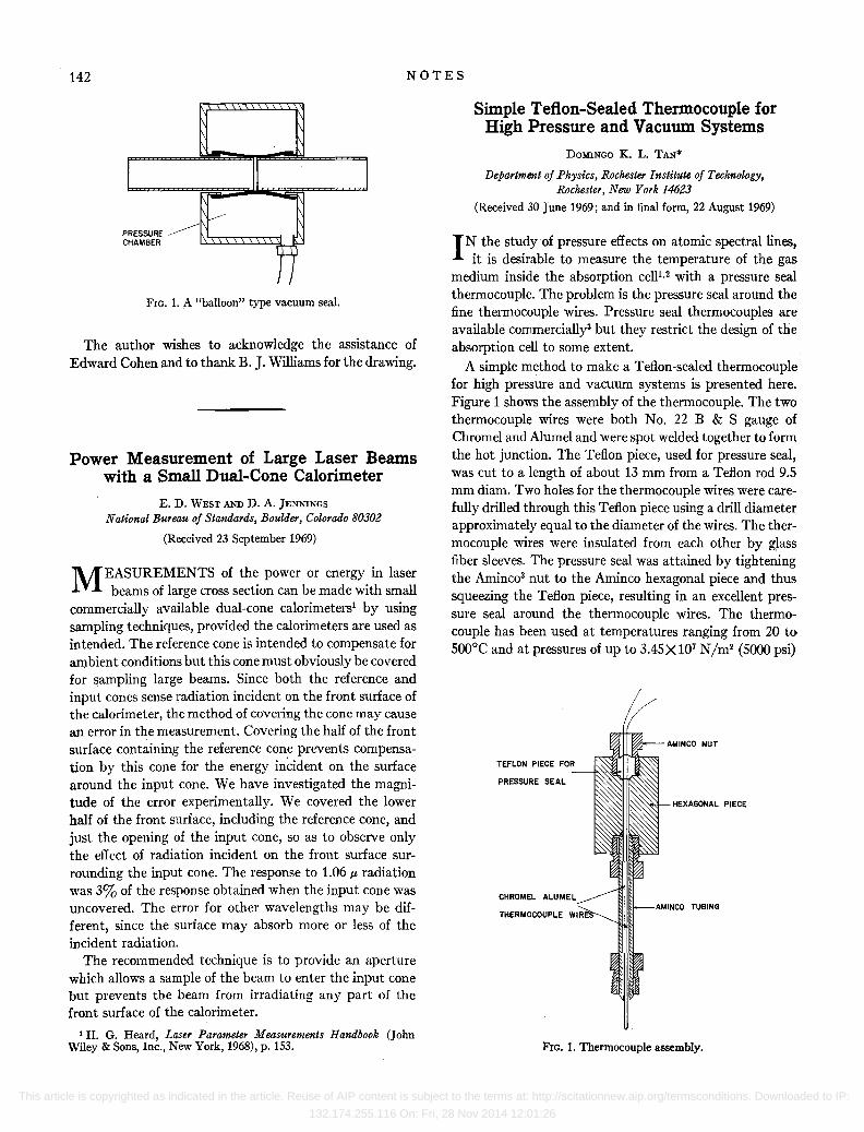
A simple method to make a Teflon-sealed thermocouple for high pressure and vacuum systems is presented here. Figure 1 shows the assembly of the thermocouple. The two thermocouple wires were both No. 22 B & S gauge of Chromel and Alumel and were spot welded together to form the hot junction. The Teflon piece, used for pressure seal, was cut to a length of about 13 mrn from a Teflon rod 9.5 mm diam. Two holes for the thermocouple wires were carefully drilled through this Teflon piece using a drill diameter approximately equal to the diameter of the wires. The thermocouple wires were insulated from each other by glass fiber sleeves. The pressure seal was attained by tightening the Aminc03 nut to the Aminco hexagonal piece and thus squeezing the Teflon piece, resulting in an excellent pressure seal around the thermocouple wires. The thermocouple has been used at temperatures ranging from 20 to 500°C and at pressures of up to 3.45 X 10⁷ N/m2 (5000 psi)
TEFLON PIECE FOR -~~I
PRESSURE SEAL
CHROMEL ALUMEL
THERMOCOUPLE WI R
AMINCO NUT
HEXAGONAL PIECE
FIG. 1. Thermocouple assembly.
This article is copyrighted as indicated in the article. Reuse of AIP content is subject to the terms at: http://scitationnew.aip.org/termsconditions. Downloaded to IP:
132.174.255.116 On: Fri, 28 Nov 2014 12:01:26