a quenching circuit of very short rise time for geiger-m$uuml$ller counters
TRANSCRIPT

This content has been downloaded from IOPscience. Please scroll down to see the full text.
Download details:
IP Address: 132.203.227.62
This content was downloaded on 14/06/2014 at 15:11
Please note that terms and conditions apply.
A quenching circuit of very short rise time for Geiger-Müller counters
View the table of contents for this issue, or go to the journal homepage for more
1969 J. Phys. E: Sci. Instrum. 2 1121
(http://iopscience.iop.org/0022-3735/2/12/438)
Home Search Collections Journals About Contact us My IOPscience
Notes on experimental technique and apparatus
electrons of 53 ev energy are +20 v on the inner plate and - 20 v on the outer. The electron collimator is grounded. The entrance to the collimator is 0.18 cm in the plane of the paper by 0.95 cm at right angles to the paper. The collimator length is 3.5 cm. The exit end measures 1.90 cm at right angles to the paper. The inner surface of the collimator is machined flat. (Earlier a toothed surface was used but this made no differ- ence.) Care must be taken to block off all alternative electron paths to the scintillator; if this is done, the ‘spurious signal’ shown in figures 3 and 4 of the paper by Wells and Bremer (1968) is removed completely. Insulators must be screened by cavities. Deflection plates at the input to the analyser can increase the transmitted signal in some cases. A 0.025 cm magnetic screen is included above the analyser. This analyser is now being used to continue the studies reported by Wells (1969). Acknowledgments We wish to acknowledge discussions on analyser design ~ i t h F F Fang and the technical assistance of L A Castonguay. References Inghram M G 1948 Adv. Electron. 1 219-68
Wells 0 C and Bremer C G 1968 J. Sci. Instrum. (J. Phys. E ) 1 (Ser. 2) 902-6
Wells 0 C 1969 Appl. Phys. Lett. 14 5-6
Journal of Scientific Instruments (Journal of Physics E) 1969 Series 2 Volume 2
A quenching circuit of very short rise time for Geiger-Muller counters
H Eckey Institut fur Kernphysik, Universitat Munster, Germany MS receiced 4 February 1969, in recised form 12 September 1969
Abstract A simple quenching circuit is described which reduces the dead time of Geiger-Muller counters by lowering the anode voltage immediately after the beginning of the discharge. The circuit delivers negative pulses with 300 v amplitude and 28 ns rise time. This extremely short rise time has not so far been achieved with similar circuits.
1 Introduction Attempts to reduce the dead time of self-quenched Geiger- Muller counters by rapidly dropping the counter voltage below the starting potential have been the subject of researches by several workers (Porter and Ramsey 1952, Picard and Rogozinski 1953, Trott 1960, Mokry 1960, Caini and Olsson 1962, Ettinger and Zastawny 1965). There are two advantages which arise from an external quenching circuit: (i) reduction of the counter dead time; (ii) prolongation of lifetime of the counter, by reducing the number of organic molecules dissociated in each discharge. The aim of this work was to design a quenching unit which possesses the advantages of: (i) simplicity (few valves only) and reliability; (ii) threshold level lower than 1 v; (iii) short rise time and high amplitude (about 200 v) of quenching pulse to ensure that the counter voltage is dropped very fast below the starting voltage; (iv) grounded cathode of the counter, as it should be in practice (Picard and Rogozinski 1953, Caini and Olsson 1962, Ettinger and Zastawny 1965).
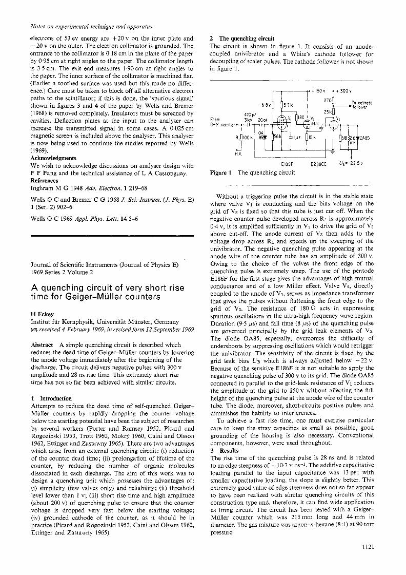
2 The quenching circuit The circuit is shown in figure 1. It consists of an anode- coupled univibrator and a White’s cathode follower for decoupling of scaler pulses. The cathode follower is not shown in figure 1.
From G-M counter
I I
EI86F E2’8CC U , = - 2 2 , 5 v
Figure 1 The quenching circuit
Without a triggering pulse the circuit is in the stable state where valve VI is conducting and the bias voltage on the grid of V3 is fixed so that this tube is just cut off. When the negative counter pulse developed across RI is approximately 0.4 v, it is amplified sufficiently in Vi to drive the grid of VS above cut-off. The anode current of V3 then adds to the voltage drop across R1 and speeds up the sweeping of the univibrator. The negative quenching pulse appearing at the anode Mire of the counter tube has an amplitude of 300v. Owing to the choice of the valves the front edge of the quenching pulse is extremely steep. The use of the pentode E186F for the first stage gives the advantages of high mutual conductance and of a low Miller effect. Valve VZ, directly coupled to the anode of VI, serves as impedance transformer that gives the pulses without flattening the front edge to the grid of V3. The resistance of 180 L2 acts in suppressing spurious oscillations in the ultra-high frequency wave region. Duration (9.5 ,US) and fall time (8 ps) of the quenching pulse are governed principally by the grid leak elements of V3. The diode OA85, especzally, overcomes the difficulty of undershoots by suppressing oscillations which would retrigger the univibrator. The sensitivity of the circuit is fixed by the grid leak bias UB which is always adjusted below -22 v. Because of the sensitive El86F it is not suitable to apply the negative quenching pulse of 300 v to its grid. The diode OA8.5 connected in parallel to the grid-leak resistance of VI reduces the amplitude at the grid to 150 v without affecting the full height of the quenching pulse at the anode wire of the counter tube. The diode, moreover, short-circuits positive pulses and diminishes the liability to interferences.
To achieve a fast rise time, one must exercise particular care to keep the stray capacities as small as possible; good grounding of the housing is also necessary. Conventional components, however, were used throughout. 3 Results The rise time of the quenching pulse is 28 ns and is related to an edge steepness of - 10.7 v ns-l. The additive capacitative loading parallel to the input capacitance was 13 pr ; with smaller capacitative loading, the slope is slightly better. This extremely good value of edge steepness does not so far appear to have been realized with similar quenching circuits of this construction type and, therefore, it can find wide application as firing circuit. The circuit has been tested with a Geiger- Muller counter which was 215 mm long and 44 mm in diameter. The gas mixture was argon-n-hexane (8 :1) at 90 torr pressure.
1121

Notes on experimental technique and apparatus
The dead time of the counter has been measured by using the method of proportional sources (Rudstam 1961). When the overvoltage was set to 120v the dead time without the circuit was 320 ps. With the quenching circuit switched on the dead time was reduced to 45 ps.
It seems possible to improve the characteristics of the quenching circuit if more reliable components are used, for example valves which possess higher mutual conductance. Acknowledgments The author wishes to express his gratitude to Professor Dr E Huster, Director of the Institut fur Kernphysik, Munster, for his kind advice and helpful support. References Caini V and Olson I 0 1962 Avk. Fys. 22 225-35
Ettinger K W and Zastawny A 1965 J. Sci. Insfvum. 42 125-6
Mokr); P 1960 & c'as. Fys. 10 526-9
Picard E and Rogozinski A 1953 J. Phys. Rad 14 304-6
Porter W C and Ramsey W E 1952 J. Fuankl. Inst. 254
Rudstam S G 1961 Nucleonics 19 62-3
Trott B B 1960 J. Sci. Instrum. 37 336-9
153-63
Journal of Scientific Instruments (Journal of Physics E) 1969 Series 2 Volume 2
The slow speed multi-sawing of brittle semiconducting compounds
W J A Powell and G W Fynn Royal Radar Establishment, Malvern, Worcs. MS received 11 August 1969, in recised form 11 September I969
Abstract The ganging of silicon carbide disks for the slow speed multi-cutting of brittle semiconducting dice is described. With twelve 0.125 mm disks and spacing collars as required (e.g. 0.25 or 0.5 mm), one hundred and twenty one dice were produced in two cutting operations with an accuracy to better than 25 pm and minimal chipping. It is concluded that the process could be readily expanded to employ up to fifty disks and a yield of approximately 2400 dice and that the use of silicon carbide disks is suitable economically.
1 Introduction The slow speed sawing (Fynn and Powell 1966) of brittle semiconducting compounds at the Royal Radar Establishment has been carried out with single diamond cutting disks usually thicker than 0.25 mm and latterly with silicon carbide wheels as thin as 0.125 mm. Where dicing of thick slices ( > 0.5 mm) is required (e.g. for the production of Gunn and avalanche diodes) there is little to gain economically between the more expensive, but very long-lived, diamond wheel and the relatively cheap but shorter lived silicon carbide.
Commercially available electrometallic or sintered diamond wheels can be obtained with varying grit size and, for delicate sawing, approximately 400 mesh is desirable. The concentra- tion does not appear to be critical, but a low one is an obvious
economic advantage. However, these disks can give variable cutting-slot dimensions, due to wheel runout and slight diamond protrusion. Thus the ganging of several of these blades could not be expected to result in a dice of, say 0.5 mm x 0.5 mm having a tolerance of better than k 50 pm. Edge chipping, too, would be more in evidence.
With these factors in mind, it was decided to try ganging silicon carbide disks, 0.25 mm x 76 mm in thickness and diameter, respectively and cut at least 100 0.5 mm squares of Gallium Arsenide, 0.5 mm thick, in two sawing operations. 2 Disks and spacers The disks used were silicon carbide disks C 320PRlVF (Universal Grinding Wheel CO Ltd, manufacturers dimensions 3 in outside diameter x 0.5 in bore x 0,005 in thick, corre- sponding to the metric sizes given above). The sawing machine was a Macrotome 2 (manufactured by Precision Devices and Systems, marketed through Metals Research Ltd).
The spacing collars between the wheels can be made out of any dimensionally convenient flat strip, metallic or non- metallic. Initially, large washers 12.52 mm centre hole x 69 mm diameter were made from mild steel shim 0.5 mm thick. However, the need for a variety of collar thicknesses when only a limited range of shim was available gave rise to the following fibre-glass technique.
Two 400 mm diameter cast iron laps were Lapmastered flat to within two bands, cleaned and treated with a silicone release agent. Pieces of glass cloth amounting to approximately the required thickness were placed on one plate and an epoxy resin Araldite MY 753 plus hardener HY 956 poured on. Three sets of specially prepared spacers (or feeler gauges suitably adjusted) were arranged at 120" round the periphery and the second lap added. A slight squeeze was maintained during the curing cycle to expel excess resin and ensure flatness. With care, the resulting resinated fibre-glass disk was flat and parallel to better than 10 pm and it was finally made into spacing collars by conventional machining techniques. 3 Specimen mounting Initially the slice of GaAs was mounted with optical stick-wax on an SRBF slab, itself affixed to the work table of a low speed saw. Though the first series of cuts were successful, the second resulted in moving some of the 0.5 mm cubes, due to adhesion breakdown. Subsequent specimens were stuck down with an epoxy resin, and the surface of the slice coated with a photo- resist at both sawing stages. This was intended to minimize chipping and provide an additional strengthening bond when the cube would otherwise have become self-supporting.
It was thought that by potting the specimen in resin at the bottom of a suitable Polythene container, then inverting the cured encapsulation for sawing, the use of an SRBF block and photoresist over-spray might be dispensed with. This method certainly resulted in virtually chip-free cutting, but had the disadvantage that the edges of the saws tended to acquire an epoxy resin build-up which slowed up the operation and finally had to be removed periodically by the method indicated in 64. 4 Disk trueing The disks obtained, though extremely flat, varied slightly in diameter and in bore size. This resulted in the application of an uneven sawing load, which was largely smoothed by the damping head; nevertheless, it was thought advisable to true the edge of the disks in situ - a practice that can be readily achieved with bonded diamond wheels only by spark erosion!
A diamond lap, 14 pm particle size, was pressed very lightly against the rotating blades, with a dial test indicator monitoring the excursion of the work table (and thus the disk run out). When the indicator showed no movement, the treatment was stopped. Obviously, the provision of a small diamond lap on the work table would give the same result more easily, and
1122