a novel zigbee- based low- cost, low- power wireless...
TRANSCRIPT

A Novel Zigbee- based Low- cost, Low- Power Wireless EKG
system
Vidyasagar Mukala, Vasileios Lakafosis, Anya Traille, Manos M. Tentzeris
GEDCIECE, Georgia Tech, Atlanta, GA 30332-250, USA
Abstract - Electrocardiogram (EKG) monitoring is of prime importance in the medical world. Using the state of art technology to take it to a wireless platform can open up a broad spectrum of wireless medical devices which have a wide range of applications in medical services, military rescue missions, home cardiovascular monitoring, especially for senior people. This paper presents a platform for developing a Zig bee based low cost, low power Wireless EKG system using the unlicenced 2.4GHz ISM band. Zig bee is based on IEEE 802.15.4 standard for Wireless Personal Area Networks (WPANs), that is being used in many commercial and research applications today, where it has become an attractive solution for low power and low cost applications. Two system designs are proposed featuring excellent ranges and potential for "smart fabric" wearable implementations.
Index Terms - Cardiovascular, commercial, medical services, electrocardiogram, wearable RF, wireless EKG, Zig bee.
I. INTRODUCTION
Electrocardiography h a s been in clinical use for the
diagnosis and monitoring of heart abnormalities for more than a century. It remains the best and least invasive method for the
task it performs. EKG measurement systems have followed
trends in technological advancement becoming more reliable,
able to perform a wider range of functions and simpler to use
as time has progressed [1]. The next step forward for the
technological advancement of electrocardiography is a
completely wireless system of measurement. Such a system
would facilitate the tasks of doctors eliminating the usage of
wires in operation theaters, as well as for senior people that
need to wear monitoring devices for a continuous tracking of
their heart condition. Another need for such a system would
arise in war scenarios where the remote monitoring of the
heart rate of every soldier would tremendously enhance rescue
chances. An accurate indication of the frontal projection of the
cardiac vector can be provided by three leads/electrodes, one
connected at each of the three vertices of the Einthoven
triangle [2]. The most prevalent and significant among them
is Lead II for diagnosing rhythm problems. Fig. l(a) shows EKG Lead II signal.
R R
T
Fig. 1 (a). Lead II EKG signal
978-1-4244-7732-6/101$26.00 ©201 0 IEEE 624
v.
1
Fig. l(b). EKG system design
Fig. 1 (b) shows the system design. The size of both designs
proposed in this paper is 7cm x 7cm x lcm. The advantage of
the designs is the low form factor. Multi hopping is done to
increase the range of transmission. However one disadvantage
of design 1 proposed in this paper is the high current demand
of Digi module which requires the usage of a high rated
battery. Hence, while implementing multi hopping with this
design power consumption is very high. This disadvantage is
overcome by using CC2530 in design 2 proposed in this paper.
The form factor of design 2 is almost same as design 1, but it
gives an extra edge over design 1 by reducing power
consumption of the device thereby effectively doubling the
battery life. Section II describes the circuit for EKG
acquisition and Section III explains the wireless modules. The
electromagnetic effects and modeling of the proposed
wearable EKG system are presented in Section IV, while
benchmarking and measurement results are presented in
Section V and Section VI.
II. EKG ACQUISITION CIRCUIT
Electrodes are used for sensing bio-electric potentials as
caused by muscle and nerve cells. EKG electrodes are of the
direct-contact type. Silver chloride electrodes are used for this
purpose because of the ease of availability, cost and its
superior temperature range (320 - 2030 F). Silver chloride
electrodes undergo little change even after long usage. The
potential of the electrode remains constant as
IMS 2010

chloride concentration remains constant. A differential input
provides the best defense against ground and noise problems
in a system implementation. The signal and its remote ground
are both routed back to an instrumentation amplifier.
Differential inputs provide immunity against noise. If twisted
pair wiring is used, any noise which is induced should be
induced equally into both wires. This is called common-mode
noise. A differential input takes the difference between the
two incoming signal wires. Any common-mode noise which
is induced along the way will be subtracted out. Passive filters
are used for the filter design because of the low power
consumption [3]. A good filter design is important to obtain a
reliable EKG signal. The standard limb lead configuration is
tested in lab and circuit is shown in Fig. 2.
R3
LeadII�
C3
R7
High Pass Filter
R'
R6
2nd o�d« Low Pass Filt"
R'
">-___ :.'\'oise free EKG signal
Fig. 2. EKG Acquisition Circuit
III. WIRELESS MODULES
The proposed system involves one transmitter that is worn
along with the electrodes, and one receiver at a distance apart
the signal is continuously recorded on the computer to which
the receiver is connected. The transmitter draws current from
the battery while the receiver draws current from the power
supply/computer. Hence, the careful design of the transmitter
section is very important as it is to be integrated along with the
electrodes and its power consumption directly impacts the
battery life. Specifically, wireless EKG design calls for the
usage of a short range and low power wireless protocol.
Hence, Bluetooth and Zig bee wireless protocols are a good
choice. Zigbee is chosen above Bluetooth because of its high
range and low power characteristics. Few good candidates for
the wireless modules are Xbee Pro (Digi), CC2530 (Texas
Instruments), Pan4555 (Panasonic), MNZB-24-BO
(Meshnetics), ZB2430 (Laird Technologies), SPZB250
(STMicroelectronics). After e x h a u s t i v e investigation,
Xbee Pro and CC2530 were analyzed as they offer lower
978-1-4244-7732-6/101$26.00 ©2010 IEEE 625
power consumption compared to the other modules. Fig. 3 shows flow chart of the system design [4]-[5].
NOISE FREE r----. ADC r----. EKG
PLOT IT USING
GUI rr
Fig. 3. Flow chart which models the device
TRANSMIT THE
SIGNAL
r OBTAIN SIGNAL
AT
Fig. 4. Wireless EKG transmitter (Front and rear view)
A. Design I
Atmega32 microcontroller is programmed for the ADC
conversion and interfaced with the Xbee Pro Zig bee module
for the wireless transmission. ADS 1178 can be used for
simultaneous sampling that is critical for transmitting mUltiple leads information. The electrodes are connected to the PCB
using twitch buttons. One prototype that has been realized on
PCB has three twitch buttons to which the electrodes are
locked as shown in Fig. 4. The receiver is USB based. Fig. 5
shows the transmitter and receiver pair-design 1.
B. Design 2
CC2530 (Texas Instruments) is programmed for ADC
conversion and wireless transmission. The advantage of this
design is that CC2530 has an integrated microcontroller with
an RF transmitter which minimizes the transmitter circuitry.
Multi hopping [6] can be implemented using this design which
helps in increasing the range of transmission. It is expected to
implement at least 6 hops. Each hop is expected to be 60m in
open space. However further experimentation should be done
in order to analyze the limit of multi hopping. Both designs
operate at a bit rate of 9600 bits/sec for transmission of a
single lead II signal. The sampling rate used is 500
samples/sec and resolution of ADC is 8 bit in design 1 and 9
IMS 2010
bit in design 2. However for the transmission of multiple
signals simultaneously a much higher bit rate is required. The
maximum bit rate of the modules used is 250kB/s. The user
can choose bit rate according to the application and set the
baud rate of the computer connected to the receiver
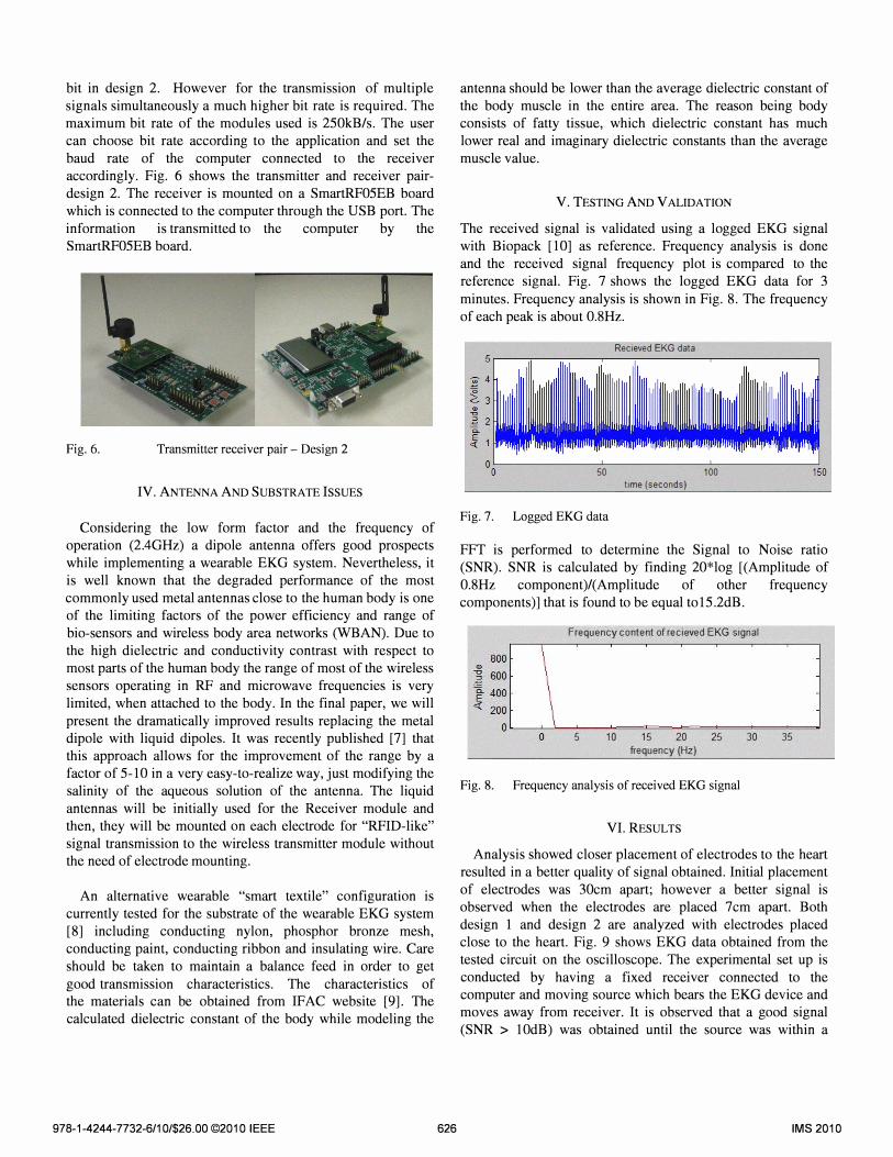
accordingly. Fig. 6 shows the transmitter and receiver pair
design 2. The receiver is mounted on a SmartRF05EB board
which is connected to the computer through the USB port. The
information is transmitted to the computer by the
SmartRF05EB board.
Fig. 6. Transmitter receiver pair - Design 2
IV. ANTENNA AND SUBSTRATE ISSUES
Considering the low form factor and the frequency of
operation (2.4GHz) a dipole antenna offers good prospects
while implementing a wearable EKG system. Nevertheless, it
is well known that the degraded performance of the most
commonly used metal antennas close to the human body is one
of the limiting factors of the power efficiency and range of
bio-sensors and wireless body area networks (WBAN). Due to
the high dielectric and conductivity contrast with respect to
most parts of the human body the range of most of the wireless
sensors operating in RF and microwave frequencies is very
limited, when attached to the body. In the final paper, we will
present the dramatically improved results replacing the metal dipole with liquid dipoles. It was recently published [7] that
this approach allows for the improvement of the range by a
factor of 5-10 in a very easy-to-realize way, just modifying the
salinity of the aqueous solution of the antenna. The liquid
antennas will be initially used for the Receiver module and
then, they will be mounted on each electrode for "RFID-like"
signal transmission to the wireless transmitter module without
the need of electrode mounting.
An alternative wearable "smart textile" configuration is
currently tested for the substrate of the wearable EKG system
[8] including conducting nylon, phosphor bronze mesh,
conducting paint, conducting ribbon and insulating wire. Care
should be taken to maintain a balance feed in order to get
good transmission characteristics. The characteristics of the materials can be obtained from IFAC website [9]. The
calculated dielectric constant of the body while modeling the
978-1-4244-7732-6/101$26.00 ©201 0 IEEE 626
antenna should be lower than the average dielectric constant of
the body muscle in the entire area. The reason being body
consists of fatty tissue, which dielectric constant has much
lower real and imaginary dielectric constants than the average
muscle value.
V. TESTING AND VALIDATION
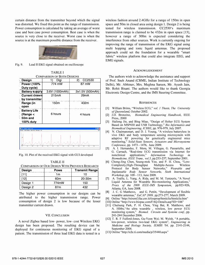
The received signal is validated using a logged EKG signal
with Biopack [10] as reference. Frequency analysis is done
and the received signal frequency plot is compared to the
reference signa\. Fig. 7 shows the logged EKG data for 3
minutes. Frequency analysis is shown in Fig. 8. The frequency
of each peak is about O.8Hz.
Recieved EKG data
50 100
Fig. 7. Logged EKG data
time (seconds)
FFT is performed to determine the Signal to Noise ratio
(SNR). SNR is calculated by finding 20*log [(Amplitude of
O.8Hz component)/(Amplitude of other frequency
components)] that is found to be equal to15.2dB.
Frequency content of recieved EKG signal
o 5 10 15 20 25 frequency (Hz)
Fig. 8. Frequency analysis of received EKG signal
VI. RESULTS
30 35
Analysis showed closer placement of electrodes to the heart
resulted in a better quality of signal obtained. Initial placement
of electrodes was 30cm apart; however a better signal is
observed when the electrodes are placed 7cm apart. Both
design 1 and design 2 are analyzed with electrodes placed
close to the heart. Fig. 9 shows EKG data obtained from the
tested circuit on the oscilloscope. The experimental set up is
conducted by having a fixed receiver connected to the computer and moving source which bears the EKG device and
moves away from receiver. It is observed that a good signal
(SNR > lOdB) was obtained until the source was within a
IMS 2010
certain distance from the transmitter beyond which the signal
was distorted. We fixed this point as the range of transmission.
Power consumption is calculated by taking an average of worst
case and best case power consumption. Best case is when the
source is very close to the receiver. Worst case is when the
source is at the maximum possible distance from the receiver.
._-------.......... ....-..---.....-I -
__ • '---'< __ -- ""
Fig. 9. Lead II EKG signal obtained on oscilloscope
TABLE I
COMPARISON OF BOTH DESIGNS Design 1 ) Digi 2) CC2530
Power (100% 774 mW 87 mW
Duty cycle)
Battery supph 3.8V (1000mAh) 2xl.5V (500mAh)
Current drawr 215mA 29mA
by transmitter
Range (in 150m 432m open
Battery Life
(Range < 8 hours 4 hours 50m and
100% duty
Fig. 10. Plot of the received EKG signal with GUI developed
TABLE II
COMPARISON OF OUR DESIGN WITH PREVIOUS RESEARCH
Design Powe Transmit Range
[11] 1m 10
[12] 80m 20-30m
Design 1 774mW 150
Design 2 87m 432
The higher power consumption in our designs can be attributed to the higher transmission range. Power consumption of design 2 is low because of the lesser transmitter current drawn.
VII. CONCLUSION
A novel Zigbee based low- power, low- cost Wireless EKG
design has been proposed. The resulting device can be
deployed for continuous monitoring of EKG signal of a
patient. The transmission of three lead EKG data is tested in a
978-1-4244-7732-6/101$26.00 ©2010 IEEE 627
wireless fashion around 2.4GHz for a range of 150m in open
space and 50m in closed area using design I. Design 2 is being tested for wireless transmiSSIOn. CC2530's maximum
transmission range is claimed to be 432m in open space [13],
however a range of 300m is expected considering the
interference from other sources. Work is currently ongoing for improving the range of transmission of the EKG signal using
multi hopping and ionic liquid antennas. The proposed approach could set the foundation for a wearable "smart
fabric" wireless platform that could also integrate EEG, and
EMG signals.
ACKNOWLEDGEMENT
The authors wish to acknowledge the assistance and support
of Prof. Sneh Anand (CBME, Indian Institute of Technology
Delhi), Mr. Abhinav, Mrs. Meghna Sareen, Mr. Ayush Jain,
Mr. Rohit Bisani. The authors would like to thank Georgia
Electronic Design Centre, and the IMS Steering Committee.
REFERENCES
[1] William Brims, "Wireless ECG," vol. I Thesis, The University of Queensland, October 2002.
[2] J.D. Bronzino, Biomedical Engineering Handbook, IEEE Press., 2000
[3] Hailong Jin, and Bing Miao, "Design of Holter ECG System Based on MSP430 and USB Technology," Bio Informatics and Biomedical Engineering, ICBBE, pp. 976-979, July 2007.
[4] N. Chaimanonart, and D. 1. Young, "A wireless batteryless in vivo EKG and body temperature sensing microsystem with adaptive RF powering for genetically engineered mice monitoring," Solid-State Sensors, Actuators and Microsystems Conference, pp. 1473 - 1476, June 2009.
[5] A. I. Hernandez, F. Mora, M. Villegas, G. Passariello, and G. Carrault, "Real-time ECG transmission via Internet for nonclinical applications," Information Technology in Biomedicine, IEEE Trans., vol. 5, pp.253-257, September 2001.
[6] Chong-Jing Chen, Seung-mok Yoo, and P. H. Chou, "LowComplexity, High-Throughput Multiple-Access Wireless Protocol for Body Sensor Networks," Wearable and Implantable Body Sensor Networks, Sixth International Workshop, pp. 109 - 113, June 2009.
[7] A. Traille, L. Yang, A. Rida, and M. M. Tentzeris, "A Novel Liquid Antenna for Wearable Bio-monitoring Applications," Procs. of the 2008 IEEE-IMS Symposium, pp.923-926, Atlanta, GA, June 2008.
[8] J. C. G Matthews, and G. Pettitt, "Development of flexible wearable antennas," EuCAP 2009, pp.273-277, March 2009.
[9] Online ''http://niremfifac.cnr.itltissprop/htmlclie/htmlclie.htm'' [10] Online .. http://www.biopac.comlFAQ-Details.asp?ID=106 .. [II] Chulsung Park, P. H. Chou, Ying Bai, R. Matthews, and
A. Hibbs,"An ultra wearable , wireless, low power ECG monitoring system," Biomed. Circuits and Systems coni, pp. 241-244 December 2006.
[12] T. R. F Fulford-Jones, Gu-Yeon Wei; M. Welsh, "A portable, low-power, wireless two-lead EKG system", Engineering in Medicine and Biology Society, fEMBS '04, pp. 2141-2144, September 2004.
[13] Online ''http://e2e. tLcomlmedia/p/35440.aspx''
IMS 2010