a novel approach of lift control in automatic car parking … · an automatic parking (multilevel)...
TRANSCRIPT
IJRET: International Journal of Research in Engineering and Technology eISSN: 2319-1163 | pISSN: 2321-7308
_______________________________________________________________________________________
Volume: 04 Issue: 06 | June-2015, Available @ http://www.ijret.org 330
A NOVEL APPROACH OF LIFT CONTROL IN AUTOMATIC CAR
PARKING USING PLC
Sharadchandra A. Amale1, Sanjay A. Pardeshi
2
1PG Student [Digital Systems], Dept. of ECE, Rajarambapu Institute of Technology, Maharashtra, India
2Professor, Dept. of ECE, Rajarambapu Institute of Technology, Maharashtra, India
Abstract In the today situation, where parking of four wheeler vehicle is very severe problem in urban region. It is crucial time to avoid the
wastage of space in urban areas, as the no of vehicles are increasing day by day. An automatic parking (multilevel) strategy
should be developed where parking problems arise intensively, which involves space reduction. In this paper a novel approach for
lift control is proposed in fully automatic Level Car Parking System which used to take cars in/out of system & park the cars.
Entire system is controlled using a Programmable Logic Controller (PLC). As speed control is required for multiple speed setting & proper stopping accuracy, the lift will be driven by the VFD (Variable Frequency Drive) for speed control. The pallet position
on lift, accurate positioning between lift-level & safety interlocks are sensed from dedicated sensor. EPLAN software for used for
electrical panel design purpose whileTWINCAT PLC control is used for auto/manual modes programming & simulated results.
Keywords: Lift control, Automatic Parking, PLC programming, IEC standard 61131-3.
--------------------------------------------------------------------***----------------------------------------------------------------------
1. INTRODUCTION
With increase in trade and commerce in the Indian metro
cities, the number of vehicles has increased abruptly. These cities bring in considerable amount of cars. Also despite of
fact that there are multiple parking spaces available for
metro cities, the parking capacity of these parking spaces is
not sufficient to satisfy to the current demand & also the
parking space location is questionable. The side of the street
are occupied with parked vehicles leading to a major
bottleneck in the smooth flow of traffic due to the absence
of adequate parking facilities. For solving the problem of
finding parking space for the increasing number of vehicles,
Multi‐level parking lots at strategic places and a rational
parking fee are inevitable. An automatic car parking system (ACPS) is a kind of mechanical system developed to reduce
the area and volume needed for parking the cars.With rising
safety & comfort standards and attention towards safety
measures and with the development in modern technologic,
elevator systems in car parking are getting better, fast and
more reliable. PLC can make a conventional elevator system
into an automatic, energy saving, safe and reliable elevator
system by using various math functions, timers, creating
interlocks etc. into its program [1].As Lifts were used as
vertical transport tool, which belong to potential energy load
and require frequent start and stop. Traditional relay control modes were replaced by PLC control method, which could
gradually transited from DC speed adjusting system to AC
variable frequency speed adjusting system [2].With the
higher and quicker development of elevators, the safety has
became more and more important and safety device
becomes particular vital. Besides the hardware, the
program‟s security is also significant. Except putting the
necessary limit switches and self locking program into some
main drive circuit, the program should also be equipped
with safety procedures [3].
In this paper, automatic control of lift in automatic car parking system is proposed. The total system is having two
lifts, three level transfer mechanisms. A single PLC
(BECKHOFF PLC) is used to control the entire parking
system. For accurate speed control lift is operated with
VFD. Speed control is required for acceleration/
deceleration & proper stopping accuracy. The flow
sequences are designed according to system sequence for lift
for manual mode & auto mode operations. The lift will be
given command to go to specific level depending upon the
storage pallet or parked car location in system. The
organization of rest of paper is as fallows sensor overview
of lift is explained in section 2. Electrical wiring diagram of VFD in section 3. Algorithm, Flowcharts in auto & manual
mode & elevator module are explained in section 4.
Performance analysis & simulation results are explained in
section 5 Concluding remarks are given in section 6.
2. OVERVIEW DIAGRAM OF LIFT
Level car parking system intends to develop an automatic
car parking system with easier storage & retrieval of cars.
The lift positions feedback are obtained from dedicated
sensors. The sensors overview along with lift movement
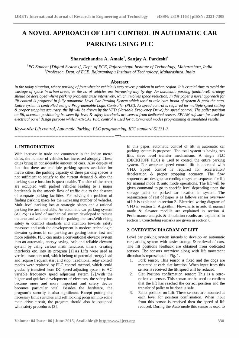
direction is represented in Fig. 1.
1. Fork sensor. This sensor is fixed and the dogs are
mounted at each slat location. When input from this sensor is received the lift speed will be reduced.
2. Slat Position confirmation sensor: This is a retro-
reflective sensor. This sensor are be used to confirm
that the lift has reached the correct position and the
transfer of pallet to be done is safe.
3. Pallet position on Lift: These sensors are mounted at
each level for position confirmation. When input
from this sensor is received then the speed of lift
reduced. During the Auto mode this sensor is used to
IJRET: International Journal of Research in Engineering and Technology eISSN: 2319-1163 | pISSN: 2321-7308
_______________________________________________________________________________________
Volume: 04 Issue: 06 | June-2015, Available @ http://www.ijret.org 331
insure the pallet position confirmation on the pallet,
thus ensuring that the pallet has reached on lift.
4. Safety sensors: If the lift pallet not engaged properly
during up/down movements, then Height/AntiLift
sensors cut and stop the operation of Lift. The over
travel sensors used to alarm the system that lift is going above the safe position limits.
Fig -1: Sensor layout diagram of lift
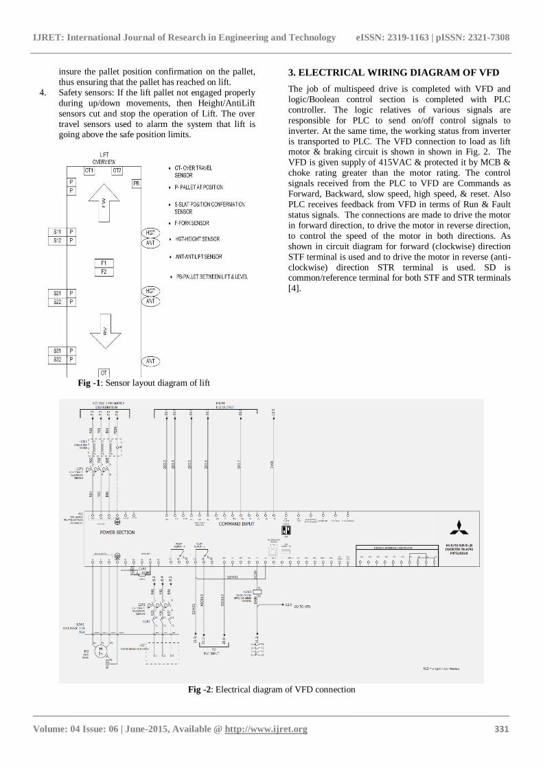
3. ELECTRICAL WIRING DIAGRAM OF VFD
The job of multispeed drive is completed with VFD and
logic/Boolean control section is completed with PLC
controller. The logic relatives of various signals are
responsible for PLC to send on/off control signals to
inverter. At the same time, the working status from inverter
is transported to PLC. The VFD connection to load as lift motor & braking circuit is shown in shown in Fig. 2. The
VFD is given supply of 415VAC & protected it by MCB &
choke rating greater than the motor rating. The control
signals received from the PLC to VFD are Commands as
Forward, Backward, slow speed, high speed, & reset. Also
PLC receives feedback from VFD in terms of Run & Fault
status signals. The connections are made to drive the motor
in forward direction, to drive the motor in reverse direction,
to control the speed of the motor in both directions. As
shown in circuit diagram for forward (clockwise) direction
STF terminal is used and to drive the motor in reverse (anti-
clockwise) direction STR terminal is used. SD is common/reference terminal for both STF and STR terminals
[4].
Fig -2: Electrical diagram of VFD connection
IJRET: International Journal of Research in Engineering and Technology eISSN: 2319-1163 | pISSN: 2321-7308
_______________________________________________________________________________________
Volume: 04 Issue: 06 | June-2015, Available @ http://www.ijret.org 332
4. OPERATIONAL SEQUENCE
Sequence of operation
There are two types of sequences manual mode sequence
and auto mode sequence.
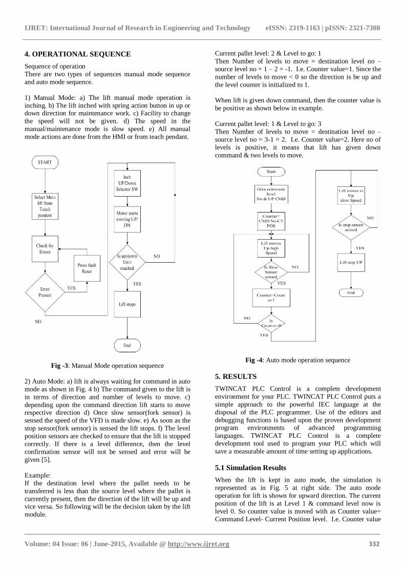
1) Manual Mode: a) The lift manual mode operation is
inching. b) The lift inched with spring action button in up or down direction for maintenance work. c) Facility to change
the speed will not be given. d) The speed in the
manual/maintenance mode is slow speed. e) All manual
mode actions are done from the HMI or from teach pendant.
Fig -3: Manual Mode operation sequence
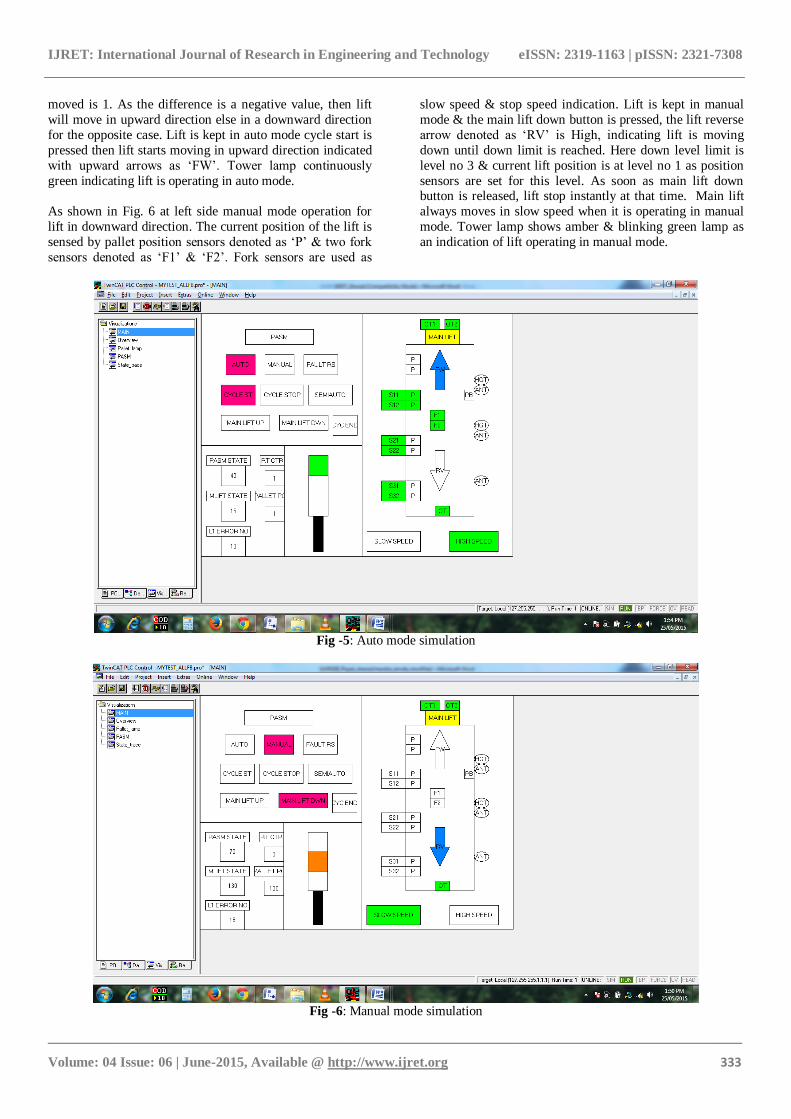
2) Auto Mode: a) lift is always waiting for command in auto
mode as shown in Fig. 4 b) The command given to the lift is
in terms of direction and number of levels to move. c)
depending upon the command direction lift starts to move respective direction d) Once slow sensor(fork sensor) is
sensed the speed of the VFD is made slow. e) As soon as the
stop sensor(fork sensor) is sensed the lift stops. f) The level
position sensors are checked to ensure that the lift is stopped
correctly. If there is a level difference, then the level
confirmation sensor will not be sensed and error will be
given [5].
Example:
If the destination level where the pallet needs to be
transferred is less than the source level where the pallet is
currently present, then the direction of the lift will be up and vice versa. So following will be the decision taken by the lift
module.
Current pallet level: 2 & Level to go: 1
Then Number of levels to move = destination level no –
source level no = 1 – 2 = -1. I.e. Counter value=1. Since the
number of levels to move < 0 so the direction is be up and
the level counter is initialized to 1.
When lift is given down command, then the counter value is
be positive as shown below in example.
Current pallet level: 1 & Level to go: 3
Then Number of levels to move = destination level no –
source level no = 3-1 = 2. I.e. Counter value=2. Here no of
levels is positive, it means that lift has given down
command & two levels to move.
Fig -4: Auto mode operation sequence
5. RESULTS
TWINCAT PLC Control is a complete development
environment for your PLC. TWINCAT PLC Control puts a
simple approach to the powerful IEC language at the
disposal of the PLC programmer. Use of the editors and
debugging functions is based upon the proven development program environments of advanced programming
languages. TWINCAT PLC Control is a complete
development tool used to program your PLC which will
save a measurable amount of time setting up applications.
5.1 Simulation Results
When the lift is kept in auto mode, the simulation is
represented as in Fig. 5 at right side. The auto mode
operation for lift is shown for upward direction. The current
position of the lift is at Level 1 & command level now is
level 0. So counter value is moved with as Counter value=
Command Level- Current Position level. I.e. Counter value
IJRET: International Journal of Research in Engineering and Technology eISSN: 2319-1163 | pISSN: 2321-7308
_______________________________________________________________________________________
Volume: 04 Issue: 06 | June-2015, Available @ http://www.ijret.org 333
moved is 1. As the difference is a negative value, then lift
will move in upward direction else in a downward direction
for the opposite case. Lift is kept in auto mode cycle start is
pressed then lift starts moving in upward direction indicated
with upward arrows as „FW‟. Tower lamp continuously
green indicating lift is operating in auto mode.
As shown in Fig. 6 at left side manual mode operation for
lift in downward direction. The current position of the lift is
sensed by pallet position sensors denoted as „P‟ & two fork
sensors denoted as „F1‟ & „F2‟. Fork sensors are used as
slow speed & stop speed indication. Lift is kept in manual
mode & the main lift down button is pressed, the lift reverse
arrow denoted as „RV‟ is High, indicating lift is moving
down until down limit is reached. Here down level limit is
level no 3 & current lift position is at level no 1 as position
sensors are set for this level. As soon as main lift down button is released, lift stop instantly at that time. Main lift
always moves in slow speed when it is operating in manual
mode. Tower lamp shows amber & blinking green lamp as
an indication of lift operating in manual mode.
Fig -5: Auto mode simulation
Fig -6: Manual mode simulation
IJRET: International Journal of Research in Engineering and Technology eISSN: 2319-1163 | pISSN: 2321-7308
_______________________________________________________________________________________
Volume: 04 Issue: 06 | June-2015, Available @ http://www.ijret.org 334
5.2 Input/ Output Testing
Table -1: I/O & communication testing
Sr.
No.
Points to be
Checked
Target Remarks/Achiev
ed
1 Input Testing As per
input list
Tested ok
2 Output
Testing
As per
Output list
Tested ok
3 Communicati
on testing
between HMI
& PLC
As per RS
422/485
Standard
Tested All HMI
tags
Input testing are completed with reference to input list in
CMS (Control mechanical Sign-off) sheet & checked
working conditions of inputs to PLC such as sensors,
buttons & switches. For BECKHOFF PLC inputs indexed with notation as “IX0.0” & outputs are represented as
notation “QX0.0”. Output testing are performed with output
list form CMS sheet & checked the working conditions of
actuators like lamp, motor, buzzer etc. are shown in table 1.
6. CONCLUSION
Automatic control of lift in Level Type Car Parking System
is designed which used to take cars in & out of system to
park. The system has several advantages to conventional car
parking system lift like reduction in construction costs, cycle
time, space requirements, highly secure & pollution control.
In addition to this, lift stopping accuracy is quite accurate
due to presence of pallet position sensors placed at all levels. In this paper for human & machine safety, interlocks are
used which take care of healthy condition all time.
Whenever an alarm occurs whole lift goes into emergency
case where the operator needs to acknowledge alarm to
avoid major accidents at parking. The alarm system has
been designed which ensures more safety of operator.
ACKNOWLEDGEMENTS
I would like to thanks my project supervisor Dr. S. A.
Pardeshi for providing the valuable guidance & Department
of Electronics & Telecommunication, Rajarambapu Institute
of Technology, Islampur & PARI LTD.
REFERENCES
[1] G. Singh, A. Agarwal, R.K. Jarial, V.Agarwal, M. Mondal, “PLC controlled elevator system”, in Proc.
IEEE Engineering and Systems (SCES) 2013, pp. 1 –
5, Feb 2013.
[2] J. Jing, Z. Xuesong, “Variable frequency speed-
regulation system of elevator using PLC technology”,
in Proc. IEEE Advanced Computer Control (ICACC)
2011, pp. 328 – 332, Jan 2011.
[3] L. Jun, L. Min, “Development of Elevator Intelligent
Safety Control System Based on PLC”, in Proc.
IEEE Computational and Information Sciences
(ICCIS)2013, pp.1963 – 1966, Jun 2013.
[4] X.Yan,Q. Zhu, H. Xu, “Design and Practice of an
Elevator Control System Based on PLC”, in Proc.
IEEE Workshop on Power Electronics and Intelligent
Transportation System 2008, pp. 94 – 99, Apr 2008.
[5] Y. Huang, J. Chen, S. Lee, Y.Weng, “Design of
Elevator Control Systems Using Statecharts”, in Proc. IEEE International Conference on Networking,
Sensing and Control (ICNSC) 2013, pp. 322 – 327,
Aug 2013.
BIOGRAPHY
Sharadchandra A. Amale, born in
Solapur District, Maharashtra, India in
1987. He received B.E. degree in
Electronics and Telecommunication
Engineering at Walchand Institute of
Technology from Solapur University in
2009 and now pursuing M-Tech. in Electronics-Digital
Systems at Rajarambapu Institute of Technology, Islampur (Sangli). His research of focus is on Automation and
Robotics.