a multiphase solute diffusion model for dendritic...
TRANSCRIPT
A Multiphase Solute Diffusion Model for Dendritic Alloy Solidification
C.Y. WANG and C. BECKERMANN
A solute diffusion model, aimed at predicting microstructure formation in metal castings, is proposed for dendritic solidification of alloys. The model accounts for the different length scales existing in a dendritic structure. This is accomplished by utilizing a multiphase approach, in which not only the various physical phases but also phases associated with different length scales are considered separately. The macroscopic conservation equations are derived for each phase using the volume averaging technique, with constitutive relations developed for the interfacial transfer terms. It is shown that the multiphase model can rigorously incorporate the growth of dendrite tips and coarsening of dendrite arms. In addition, the distinction of different length scales enables the inclusion of realistic descriptions of the dendrite topology and relations to key metallurgical parameters. Another novel aspect of the model is that a single set of conser- vation equations for solute diffusion is developed for both equiaxed and columnar dendritic solidification. Finally, illustrative calculations for equiaxed, columnar, and mixed columnar- equiaxed solidification are carried out to provide quantitative comparisons with previous studies, and a variety of fundamental phenomena such as recalescence, dendrite tip undercooling, and columnar-to-equiaxed transition (CET) are predicted.
I. INTRODUCTION
M O D E L I N G of transport phenomena occurring dur- ing dendritic alloy solidification has received consider- able research attention in the past several decades, m Recently, interest has been focusing on an important and promising approach, namely micro-macroscopic mod- eling. The main goal of this approach is to incorporate descriptions of fundamental microscopic phenomena, such as nucleation, undercooling, and grain growth, into macroscopic heat-flow calculations in order to predict microstructure formation of a solidifying material on the system scale. A review of micro-macroscopic modeling has been provided by Rappaz [2] and recent developments have been reported in conference proceedings. [3]
In an attempt to achieve detailed coupling between micro- and macroscopic phenomena, Ni and Beckermann [4] proposed a two-phase model for mass, momentum, energy, and species transport in a solidi- fying system. The model is formulated by viewing the solid and liquid phases separately and averaging the field properties of each phase over a representative elemen- tary volume. Through the volume averaging process, phase interaction terms appear in the resulting macro- scopic balance equations that reflect the effects of the transport phenomena occurring on the microscopic scale. These interaction terms are all proportional to the solid/liquid interfacial area-per-unit volume, which rep- resents the sole microscopic length scale. The same volume-averaging technique was employed by Ganesan and Poirier LS] to derive macroscopic mass and momen- tum equations for a stationary solid phase.
Nevertheless, volume-averaged two-phase models are
C.Y. WANG, Graduate Research Assistant, and C. BECKERMANN, Associate Professor, are with the Department of Mechanical Engineering, The University of Iowa, Iowa City, IA 52242.
Manuscript submitted November 12, 1992.
not well suited for incorporating microstructural features present in dendritic solidification. This problem origi- nates from the single-scale averaged description of phase behaviors. In traditional volume averaging, no distinc- tion is made between properties of a phase associated with different microscopic length scales. The phenom- ena occurring on various microscopic length scales are smeared and modeled using a single mean characteristic length (i.e., the interfacial area concentration). In real- ity, in dendritic growth there exist at least three disparate microscopic length scales that are smaller than the char- acteristic size of an averaging volume: (1) the overall size of the crystal or the primary dendrite arm spacing, (2) the secondary dendrite arm spacing, and (3) the ra- dius of a dendrite tip. Obviously, the transport phenom- ena occurring on the various microscopic scales differ greatly from one another and cannot be well described based on a single mean characteristic length, although they are all taking place within the same averaging vol- ume. In other words, a single-scale model provides in- sufficient resolution to capture dynamic behaviors on several microscopic length scales. Such resolution is, however, required for the complete incorporation of microscopic effects in a macroscopic model and the pre- diction of microstructure formation in a solidifying system.
Considerable progress has been made to account for the heterogeneous nature of microstructures in the micro-macroscopic modeling of both equiaxed L6,7'8] and columnar [9,1~ dendritic solidification. In the models of equiaxed dendritic growth, the necessary resolution is obtained by viewing the liquid phase in a control volume as two distinct fluids associated with two length scales: the liquid within the dendritic structure and the liquid outside the equiaxed grain. It is then possible to sepa- rately account for the different solute diffusion phenom- ena in the interdendritic structure and the dendrite tip region and, more importantly, to incorporate a growth
METALLURGICAL TRANSACTIONS A VOLUME 24A, DECEMBER 1993--2787
model for the dendrite tips. Similarly, when analyzing columnar dendritic solidification, Flood and Hunt t9j dis- tinguish between the liquid in the interdendritic region and that outside the columnar front and also take into account the undercooling at the primary dendrite tips.
Although these recent investigations have obtained successful results, they fail to provide a consistent and general framework for micro-macroscopic modeling of dendritic solidification. For example, in Dustin and Kurz 's model t6J of equiaxed growth and in Flood and Hunt 's model OJ of columnar solidification, the growth model for the dendrite tips is introduced at the expense of not conserving solute outside of the grain envelope or at the columnar front.t21 The same practice was repeated by Kerr et al. tlu The only model that not only conserves solute but also incorporates a dendrite-tip-growth model in a rigorous and consistent manner is due to Rappaz and Thevoz. tTl Unfortunately, lengthy calculations are re- quired to obtain the microscopic solute profile outside each equiaxed grain, which limits its utility in a macro- scopic model. Although the analytical version of the model t81 is suitable for incorporation into a macroscopic model, it is implied that the average concentration of the liquid outside of the grain remains at its initial value, which may not be valid in some cases (e.g., in the pres- ence of macrosegregation). Finally, none of the previ- ously mentioned micro-macroscopic models accounts for finite-rate solute diffusion in the solid on a microscopic scale.
The aim of this article is to formally and rigorously develop a micro-macroscopic model of dendritic solid- ification by utilizing a multiphase approach and volume averaging. Moreover, an attempt is made to construct a unified theory for both equiaxed and columnar dendritic solidification. As a first step, this article solely deals with solute diffusion. Due to the large value of the Lewis number for metallic alloys, thermal equilibrium is as- sumed to prevail on a microscopic scale, while the macroscopic temperature distribution is considered to be known from the solution of the energy equation. The inclusion of melt convection and solid movement is non- trivial and will be covered in a future publication. In the following, the basic model is introduced, and the rele- vant supplementary relations are provided, with the last two sections focusing on practically useful limiting cases and both qualitative and quantitative comparisons with previous studies.
I I . BASIC M O D E L C O N S I D E R A T I O N S
A. Multiphase Approach
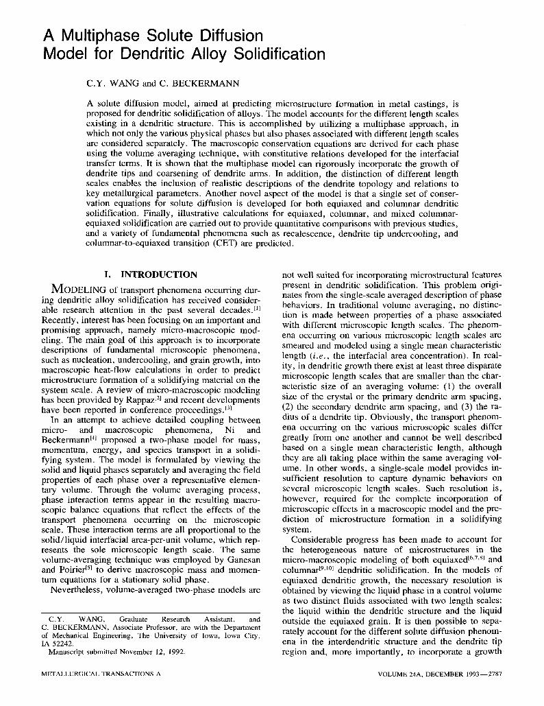
Consider a small volume element that contains several equiaxed or columnar dendritic crystals, as schemati- cally illustrated in Figure 1, in which two different inter- facial length scales can be distinguished. An interfacial scale (having the unit of length) is defined as the ratio of the volume of the structure to the interfacial area. In the equiaxed case, the solid crystal and the interdendritic liquid share a common interfacial length scale of 10 -5 to 10 -4 m, whereas the interface between the liquid out- side the grains and the interdendritic liquid has a larger length scale (of the order of 10 -4 to 10 -3 m). The same
/ V 0
( (a)
V0
(b)
Fig. 1 - - Schematic illustration of the averaging volume and the den- drite envelopes (interrupted lines) for (a) equiaxed growth and (b) columnar growth.
is true for the columnar case, if one notes the difference between the primary and secondary arm spacings (see Figure l(b)). The size of the volume element is chosen such that it is much larger than all interfacial length scales but small compared to the system scale (of the order of 10 -j to 10 ~ m). Hence, a proper volume element could have a radius between 10 -3 and 10 -2 m. A volume element of this size is what all macroscopic models are actually based on.
The hypothetical interface between the interdendritic liquid and the liquid outside the crystals is referred to as the dendrite envelope. The specification of this envelope is somewhat subjective. However, a reasonable choice appears to be a smooth surface connecting the primary and secondary dendrite arm tips, as shown by the inter- rupted line in Figure 1. More details on the envelope topology can be found in Section IV.
Now, the volume element can be considered to consist of three different phases: the solid phase and the two liquid phases. The two liquid phases separated by the dendrite envelope are distinguished by their different interfacial length scales. This multiphase approach to a heterogeneous system is realistic, since a fluid within a structure of a larger scale really could have different macroscopic properties than the same fluid in a smaller scale structure. It has long been recognized that the ef- fective transport properties of a fluid within a micro- structure are not only dependent on its physical
2788--VOLUME 24A, DECEMBER 1993 METALLURGICAL TRANSACTIONS A
properties but also on the geometry of the structure.t~2,13,14]
In the multiphase approach, separate macroscopic conservation equations are formulated for each phase. These macroscopic equations are linked through inter- facial transfer terms, which reflect the microscopic transport phenomena present at the interfaces. The new interface between the two liquid phases (i.e., the enve- lope), thus, provides an opportunity to incorporate ad- ditional microscopic phenomena in the model and transmit information from the two different length scales into the macroscopic equations. The macro- scopic conservation equations are derived using the volume-averaging technique, which is described in Section II-B.
B. Volume Averaging
Volume averaging has been a popular technique to de- rive macroscopic conservation equations for multiphase transport phenomena with and without phase change. In its application to solidification, a number of advantages have been pointed o u t . [41 Volume averaging shows how the various terms in the macroscopic equations arise and how the resulting macroscopic variables are related to the corresponding microscopic ones. This gives consid- erable insight into the formulation of constitutive rela- tions for the incorporation of the microscopic phenomena. In this work on heterogeneous solidification systems, volume averaging is also attractive, because it shows how physical phenomena occurring on one length scale are linked to those on another scale in a macro- scopic description.
The averaging volume, Vo, is shown in Figure 1. Rig- orously, the spatial smoothing of a physical property be- longing to the smaller-scale phase over the averaging volume, Vo, requires the knowledge of the transport equations first averaged over a smaller volume. Hence, in order to develop a macroscopic equation for the smaller-scale phase in a heterogeneous system, based on the volume Vo, the microscopic or point equation must be spatially averaged successively over two averaging volumes of different size. This is the basic idea under- lying the so-called dual-scale volume-averaging tech- nique that was r ecen t ly developed by Wang and Beckermann. tla However, the averaging theorems es- tablished for that technique reduce identically to those in the conventional volume-averaging method, if it is as- sumed that the smaller averaging volume is spatially in- dependent (but it can be time dependent) inside the larger volume, Vo. Therefore, for the sake of simplicity, the conventional volume-averaging method is employed here, and each fluid having a distinct length scale is viewed as a separate phase. While the details of the method have been well documented; ~6 19] only the av- eraging theorems are provided in the following:
< Oqrk~_O(~k> 1 fa ~ k w ' n d A [la] --o-ft / ot Vo
(V'k> = V(**) + ~00 *kndA [lb] k
where the averaging operator and the intrinsic volume average are defined, respectively, as 1L
(~k) = ~ Xkqtk dV [2a]
l f v ~ (*k)k = -~k Xk*kdV [2b]
with Xk denoting a phase function, equal to unity in phase k and zero elsewhere, and Vk is the volume of phase k in V0.
The factor n in Eqs. [la] and [lb] denotes the out- wardly directed unit vector normal to an interface, and w is the velocity of the interface. Note that Ak stands for the total interfacial area of the k-phase adjacent to all other phases j; i.e.,
A~ = E AkJ [3] j,j~:k
Equations [la] and [lb] are utilized in Section I I -C to derive the macroscopic transport equations.
C. Macroscopic Equations
In the absence of melt convection and solid move- ment, the relevant equations governing solute diffusion are the statements of mass and solute conservation within each phase. Their microscopic versions can be written as
Opk - - = 0 [41 Ot
and
0 ~ (pkCk) = --V "Jk [5] Ot
where Jk is the diffusive species flux in phase k. Making use of the averaging theorems, Eqs. [la] and [lb], we obtain the corresponding macroscopic versions as follows:
and
0 - - ( p k e ~ ) = ~'~ F~j Ot j, je'k
[61
0 O--t (p~ek (Ck> k) = - V " ((jk)) + E Jkj [7]
j , j#k
where ek is the volume fraction of phase k within the averaging volume, Fkj denotes the net rate of mass ex- change of phase k at the k-j interface, and Jkj is the spe- cies transfer rate of phase k at the k-j interface. The interfacial species transfer rate, Jkj, consists of two parts: namely,
Jkj = J[j + J{j [81 where the first part is due to interfacial movement and the second arises from species diffusion. Note that the motion of the solid-interdendritic liquid interface is caused by phase change, whereas that of the dendrite
METALLURGICAL TRANSACTIONS A VOLUME 24A, DECEMBER 1993--2789
envelope is induced by dendrite tip growth. The volume averaging procedure results in the following explicit re- lations for the interfacial transfer terms: 1s
= pkw" ndA [9]
Jg = p C:'-da [lOl
�9 1 s JJkj - Vo jk . ndA [11]
kj
These terms are constrained by interfacial balances on each k-j interface; i .e. ,
Fk; + Yak = 0 [ 12]
and
Jks + J : = 0 [13]
Obviously, an overall interfacial balance follows by summing up the interracial balances for each interface. The specification of the interfacial transfers in terms of macroscopic variables requires the development of con- stitutive relations for the system under consideration.
III. BASIC CONSTITUTIVE RELATIONS
Constitutive relations are formulated for a three-phase system consisting of the solid (k = s), the interdendritic liquid (k = d), and the extradendritic liquid outside the dendrite envelopes (k = l), so that G + ed + ez = 1. It is further assumed that the solid (s) has only pointwise contact with the liquid (l) outside the dendrite envel- opes, so that
Asd = Ads = As, Adl = Aid = A~, and A,t = Aa = 0
[141
These geometrical relationships imply that there exists no direct coupling between phases s and l, while phase d interacts with both phases s and 1.
A. Model ing o f the Interfacial Transfers Due to Interface Movemen t
The exact expressions for the interfacial transfers of mass and species due to interface movement are given by Eqs. [9] and [10]. Using the mean value theorem for integrals, these terms can be modeled as the product of an interracial area concentration, Ss = As/Vo or Se = Ae/Vo, and a mean interracial flux. Hence, at the s-d interface:
F~d = -F~s = S~p,v~,s [15]
where # , , is defined as the average normal velocity of the solid-interdendritic liquid interface, which is solely due to phase change. Similarly, at the d-I interface:
Fdt = - Ftd = S~pavv,,~ [ 16]
where uv,~ denotes the average normal velocity of the dendrite envelope. As mentioned before, the movement
of the envelope is related to the kinetics of the dendrite tips, which is discussed in more detail in Section VI.
In a like manner, the interfacial species transfers due to interface movement can be modeled as
J~r.d = CsdF,d; JVa, = Ca, Fd, [171
for the s-d interface, and
j r = Ca,Fa,; j r = CzaFtd [18]
for the d-I interface. The overbars denote an average over the interfacial area, As o r A e.
B. Model ing o f the Interfacial Species Transfers Due to Dif fusion
The exact expression for the interracial species trans- fer due to diffusion, J~j, is given by Eq. [11]. Physically, this term describes the interfacial diffusion process caused by species concentration gradients. The integral in Eq. [ 11 ] can be evaluated again as the product of the interfacial area concentration, S, and a mean interracial diffusive flux. The flux is directly proportional to its driving force, namely, the difference between the inter- facial and volume-averaged concentrations of a phase. On the other hand, the flux is inversely proportional to a so-called solute diffusion length, l, which characterizes the resistance to diffusion. Hence, the following math- ematical expressions can be written down:
J.~a S D = ,Ps 7 - (C,a - ( C y ) [19] lsd
and
j~.,. Dd _ = S,p,t-~a ~ (Cj~ - (Ca) a) [201
for the s-d interface. It should be noted that Pd and Dd are not necessarily equal to Pt and Dr, respectively, be- cause these properties are functions of the local concen- tration and temperature. Likewise, one has that
Dd - JJlt = SePd ~ (Cd, -- ( C a ) d) [21]
and
DI J{d = SePl ~ld (Cld -- (Cl) l) [221
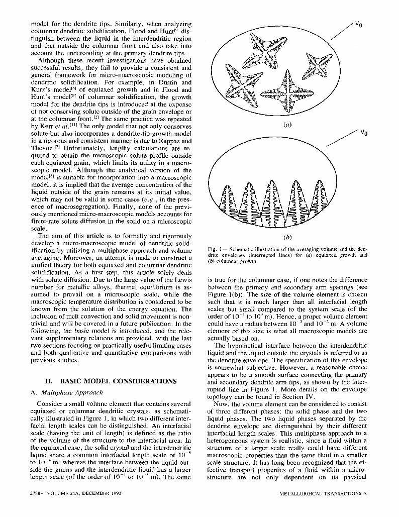
at the d-I interface. Figure 2 schematically illustrates the microscopic con-
centration distributions in the solid, interdendritic, and extradendritic liquid regions. The interfaces depicted in Figure 2 represent infinitesimal sections of the interfaces shown in Figure 1 and are drawn, for simplicity, as straight lines. The physical meanings of the various dif- fusion lengths, l, are also shown therein. Mathemati- cally, a diffusion length is defined as
G s - (Ck) k
lkj - OCk [23]
On kj
2790- -VOLUME 24A, DECEMBER 1993 METALLURGICAL TRANSACTIONS A
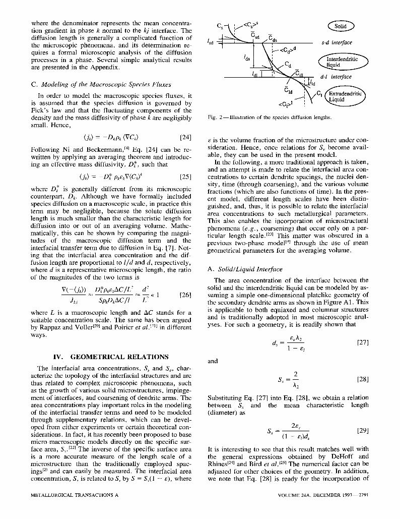
where the denominator represents the mean concentra- tion gradient in phase k normal to the kj interface. The diffusion length is generally a complicated function of the microscopic phenomena, and its determination re- quires a formal microscopic analysis of the diffusion processes in a phase. Several simple analytical results are presented in the Appendix.
C. Modeling of the Macroscopic Species Fluxes
In order to model the macroscopic species fluxes, it is assumed that the species diffusion is governed by Fick's law and that the fluctuating components of the density and the mass diffusivity of phase k are negligibly small. Hence,
(Jk) = --Dkpk (VCk) [24]
Following Ni and Beckermann, ~41 Eq. [24] can be re- written by applying an averaging theorem and introduc- ing an effective mass diffusivity, D*, such that
(jk) = - D * pkekV(Ck) k [25]
where D* is generally different from its microscopic counterpart, Dk. Although we have formally included species diffusion on a macroscopic scale, in practice this term may be negligible, because the solute diffusion length is much smaller than the characteristic length for diffusion into or out of an averaging volume. Mathe- matically, this can be shown by comparing the magni- tudes of the macroscopic diffusion term and the interfacial transfer term due to diffusion in Eq. [7]. Not- ing that the interfacial area concentration and the dif- fusion length are proportional to l i d and d, respectively, where d is a representative microscopic length, the ratio of the magnitudes of the two terms is
V(--(jk)) * 2 d 2 D k pkekAC/L . . . . << 1 [26]
Jk# SpkDkAC/1 L2
where L is a macroscopic length and AC stands for a suitable concentration scale. The same has been argued by Rappaz and Voller t2m and Poirier et al. ~21~ in different ways.
I V . G E O M E T R I C A L R E L A T I O N S
The interfacial area concentrations, Ss and Se, char- acterize the topology of the interracial structures and are thus related to complex microscopic phenomena, such as the growth of various solid microstructures, impinge- ment of interfaces, and coarsening of dendrite arms. The area concentrations play important roles in the modeling of the interracial transfer terms and need to be modeled through supplementary relations, which can be devel- oped from either experiments or certain theoretical con- siderations. In fact, it has recently been proposed to base micro-macroscopic models directly on the specific sur- face area, Sv. E22~ The inverse of the specific surface area is a more accurate measure of the length scale of a microstructure than the traditionally employed spac- ings E2J and can easily be measured. The interfacial area concentration, S, is related to Sv by S = Sv(1 - e), where
lsd ~ s d /Cds s-d interface
/dll ' ~ 0 1 '"~Odl . , d-l interface / "~.~lld .,,
Cld ~ ,,01 E~xx~den~t~lc �9 ~ ~" k, Liquid J
<CI>I ! l ~ #
Fig. 2--Illustration of the species diffusion lengths.
e is the volume fraction of the microstructure under con- sideration. Hence, once relations for Sv become avail- able, they can be used in the present model.
In the following, a more traditional approach is taken, and an attempt is made to relate the interfacial area con- centrations to certain dendrite spacings, the nuclei den- sity, time (through coarsening), and the various volume fractions (which are also functions of time). In the pres- ent model, different length scales have been distin- guished, and, thus, it is possible to relate the interfacial area concentrations to such metallurgical parameters. This also enables the incorporation of microstructural phenomena (e.g., coarsening) that occur only on a par- ticular length scale. L23j This matter was obscured in a previous two-phase model t4J through the use of mean geometrical parameters for the averaging volume.
A. Solid~Liquid Interface
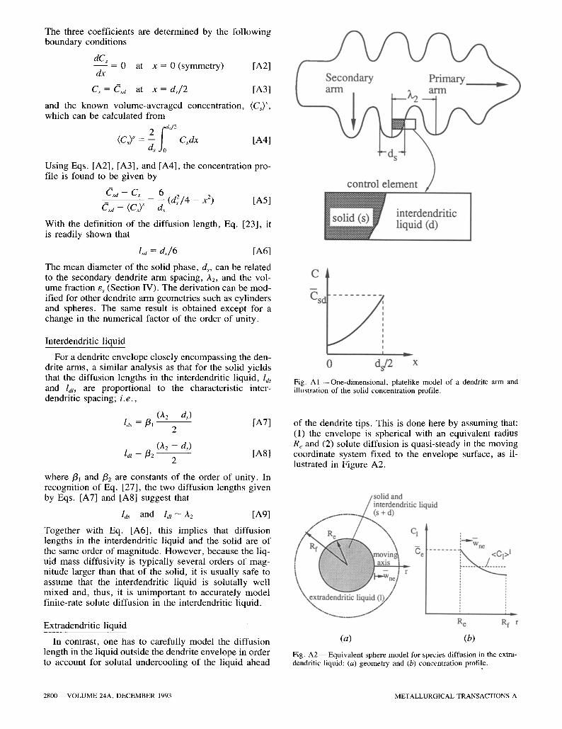
The area concentration of the interface between the solid and the interdendritic liquid can be modeled by as- suming a simple one-dimensional platelike geometry of the secondary dendrite arms as shown in Figure A1. This is applicable to both equiaxed and columnar structures and is traditionally adopted in most microscopic anal- yses. For such a geometry, it is readily shown that
es A2 d, - [27]
1 - ez
and
2 Ss = - - [28]
/~2
Substituting Eq. [27] into Eq. [28], we obtain a relation between Ss and the mean characteristic length (diameter) as
2e~ Ss - [29]
(1 - eDds
It is interesting to see that this result matches well with the general expressions obtained by DeHoff and Rhines t24~ and Bird et al. t251 The numerical factor can be adjusted for other choices of the geometry. In addition, we note that Eq. [28] is ready for the incorporation of
METALLURGICAL TRANSACTIONS A VOLUME 24A, DECEMBER 1993--2791
the coarsening effect. For example, by using the coars- ening law established by Kattamis et al. 32<
~2 ~- [~tla/3 [301
Eq. [28] gives
Ss ~ C 1/3 [31]
where t,, is the local "aging" time. This result is consis- tent with the coarsening experiments conducted by Marsh et al.t271 at a constant solid fraction.
Note that due to the assumption of a one-dimensional platelike geometry for the solid/liquid interface, the interfacial area concentration, S,, is not an explicit func- tion of the solid volume fraction (but S~ is; see earlier). This may not be a good approximation during the initial and final stages of solidification when the interface ex- periences qualitative changes in its topology. This prob- lem can be overcome by using the correction factor for the interfacial area due to Avrami t28~ to account for im- pingement of interfaces or the empirical relation pro- posed by Speich and Fisher. lz9J
B. Dendrite Envelope
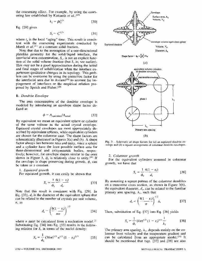
The area concentration of the dendrite envelope is modeled by introducing an envelope shape factor de- fined as
~) = Aequivalent/Aactual [32]
By equivalent we mean an equivalent sphere or cylinder of the same volume as the actual crystal envelope. Equiaxed crystal envelopes are most appropriately de- scribed by equivalent spheres, while equivalent cylinders are chosen for the columnar case. The shape factors are schematically illustrated in Figures 3(a) and (b). A shape factor always lies between zero and unity, since a sphere and a cylinder have the least possible surface area for three-dimensional and axisymmetric bodies, respec- tively; however, for envelope shapes similar to the ones shown in Figure 3, ~be is relatively close to unity. 13~ If the envelope is shape preserving during growth, ~b,, can be taken as a constant.
1. Equiaxed growth For equiaxed growth, it can easily be shown that
1 6 ( 1 - el) Se - [331
Note that this result is consistent with Eq. [29]. In Eq. [33], d~ is the diameter of the equivalent sphere that can be related to the number of crystals per unit volume, n , a s
(6(1_ - e,)) 1/3 [34] de= \ n~r
where n must be calculated from a nucleation model, t21 Substituting Eq. [34] into Eq. [33] results in the follow- ing relation for & in terms of the nuclei density:
1 1 Se = ~ee (36~') /3 h i /3 ( l - - e l ) 2 /3 [35]
J
j
Equiaxed dendrite
~ Envelope
Surface area, A e Volume, V e
Envelope volume equivalent sphere
Volume, V e
Diameter, d e
(a)
equivalent volume cylinders e~['~ of dendrite envelopes
"~" ~ i phase I ~'1
Primary arm spacing
(b)
Fig. 3 - - S c h e m a t i c of shape factors for (a) an equiaxed dendrite en- velope and (b) a square arrangement of columnar dendrite envelopes.
2. Columnar growth For the equivalent cylinders assumed in columnar
growth, we have that
1 4 ( 1 - et) S,, = - - [36]
~be de
By assuming a square pattern of the columnar dendrites on a transverse cross section, as shown in Figure 3(b), the equivalent diameter, d,,, can be related to the familiar primary arm spacing, hi, such that
( 4(1 - eO de = " ~r ~1 [ 3 7 ]
Then, substitution of Eq. [37] into Eq. [36] yields
1 (4~)1/2 ( l - - e l ) 1/2 1 [38] :
The primary arm spacing, AI, depends mainly on the co- lumnar front velocity and the temperature gradient and can be calculated from an appropriate model. ~3u It should be mentioned that Eqs. [37] and [38] are also
2792--VOLUME 24A, DECEMBER 1993 METALLURGICAL TRANSACTIONS A
valid for other arrangements of the dendrites except for a slight change in the numerical factor.
By comparing Eq. [35] with Eq. [38], it is apparent that the number density of equiaxed crystals, n, can equivalently be viewed as the number density o f primary arms in columnar solidification, that is n / ~ 1/h~. Furthermore, Eqs. [35] and [38] reveal the following im- portant parametric relation:
S e ~ rt 1/3 or l/A1 [39]
The final equivalent radius (R I = de~2) of a dendrite, which is useful in the calculation of the diffusion lengths (Appendix), can be obtained from Eq. [34] or [37] by taking el = 0. Similar to the solid/liquid interface, the envelope area concentrations expressed by Eqs. [35] and [38] need to be modified during the initial and final stages of solidification. In particular, Se should be equal to zero for el = 0.
V. T H E R M O D Y N A M I C R E L A T I O N S
Under the assumption of local thermodynamic equi- librium, the following conditions are valid at the solid/ interdendritic liquid interface:
Csd/Cd~ = K [40]
T - T , Cd~ -- - - [41]
mt
where we utilize the symbol T without a subscript to rep- resent the single temperature of an averaging volume (Section I).
At the d-l interface, phases d and l are actually the same liquid. Hence,
Cat = Cld = Q [42]
where Ce denotes the liquid concentration on the dendrite envelope. The envelope concentration cannot be ob- tained from the phase diagram but is determined by the interfacial species balance. Substituting Eqs. [16], [18], [21], and [22] into Eq. [13] results in
(Ct~ - Cdz) Plane
Dl Dd = pi~t d (Ctd -- <CJ) + Pd --Idi (Call -- <Ca> a) [43]
In recognition of Eq. [42], Eq. [43] can be solved for C~ to obtain the following:
piDi (CS + pdDd (Cd) d
Ce = lid lal [441 ptDl paDd
lla ldt
The use of Eq. [44] to determine Ce excludes the pos- sibility of obtaining the envelope velocity, #he, from Eq. I45]. Therefore, this velocity is no longer deducible from the conservation equations themselves but must be supplied through an independent relation governing the growth of the dendrite envelope. This is accomplished in Section VI.
VI . G R O W T H M O D E L F O R T H E D E N D R I T E E N V E L O P E
As shown in Figure 1, the envelope is a smooth sur- face connecting both the primary and secondary dendrite arm tips. Therefore, the envelope velocity, rPne, can be taken to be equal to some mean tip velocity. Generally, each tip moves at a different speed depending on the local solutal undercooling in the extradendritic liquid ad- jacent to the tip. In particular, there may be considerable differences in the speeds of the primary and secondary dendrite arm tips. In spite of this complex situation, it is assumed in this study that the mean dendrite tip ve- locity and, hence, the envelope velocity can be uniquely related to the average solutal undercooling in the extra- dendritic liquid, i .e. , Ce - (CJ . The irregular topog- raphy of the envelope caused by the different speeds of the dendrite tips is accounted for through the use of the envelope shape factor as described in Section IV.
Numerous studies have been performed to establish a relation between the dendrite tip undercooling and its growth velocity, and the basic derivations can be found in References 31 and 32. For conciseness, only the final result, written in terms of the present nomenclature, is stated here:
D t m ( K - 1)C~ [Iv-L(f~)] 2 [451 ~ne = 7rZF
where f~ is the dimensionless solutal undercooling and is defined as
Ce - (C i ) l 1~ - _ [46]
C e ( l - t()
and Iv- t ([1) is the inverse function of the Ivantsov trans- port function, t3~] Equation [45] assumes a parabolically shaped dendrite tip and neglects the thermal and cur- vature undercoolings. It is worth noting that Eq. [45] is applicable to both columnar and equiaxed growth, be- cause only solute diffusion is considered. If adopting the hemispherical needle approximation to the shape of a tip, the Ivantsov function simplifies to ~ = Iv(Pe,) = P e t , [3H s o that
Iv -1 (12) = ~ [47]
Then, substituting Eq. [47] into Eq. [45], we obtain the following quadratic relation:
Dim(K - - 1)Ce ~'~2 [48] Wne = w2F
This equation has been used by Rappaz and Thevoz t71 and is employed below in the comparisons for equiaxed solidification.
V I I . S U M M A R Y O F G O V E R N I N G EQUATIONS
A set of model equations is summarized and discussed in this section for situations where the following as- sumptions can be invoked.
METALLURGICAL TRANSACTIONS A VOLUME 24A, DECEMBER 1993--2793
(1) Species diffusion on a macroscopic scale is neg- ligible for all phases (see also Eq. [26]); i.e.,
D * = D * = D * ~ 0 [49]
(2) The densities of the solid and the liquid phases are equal and constant.
Under these circumstances, the general model pre- sented in the preceding sections reduces to a system of five conservation equations, which can be summarized as follows:
Dendrite envelope motion
0 SeDlml (K- 1)Ce - - ( e , + e d ) = S ~ W ~ = at "n'2F
Solute balance of phase s
O(es(CY) _ Csa __Oe" + S,D,
Ot Ot lsd
Solute balance of phase d
O(eZCd)~) (Ce - C',~s) Oe--2s at ot
[IV 1 (~'~)]2 [50]
(Q~ - (c3) [511
C =e - - + OEd S~D~ + Ot
SsD d _
(Cds -- (C J ) ld,
SeDa + - - (C~ - (c ,S)
lat
[52]
Solute balance of phase 1
O(et(CJ) C~ Oe, S~Dt - - - - - + ( C , , - ( C , ) ' ) [ 5 3 ]
Ot Ot ltd
Interfacial solute balance at the s-d interface
dE s _ SsDd S,.D, (Cd~. - C~.d) at l ~ (Cd.,. - - (Cd) d) + ~ (C~d -- ( C , ) ~)
[54]
Equations [51] through [54] have been obtained by elim- inating v~,,, and ~,~ in favor of es and ed. They constitute a full system of differential equations for five unknowns: e~, ed, (Csf, (Ca) d, and (CJ , while C~ is calculated from Eq. [44]. When supplied with the expressions for the diffusion lengths, thermodynamic conditions, and geo- metrical relations, these equations represent a complete model for solute diffusion. It is noteworthy that all model equations have clear physical interpretations. For example, Eq. [51 ] simply states that the change in mass of solute in the solid results from the combined contri- butions of movement of the solid/liquid interface and solute diffusion across the interface. Another salient fea- ture of the present model is that it provides the same set of conservation equations for both equiaxed and colum- nar dendritic solidification. In other words, the model represents a unified theoretical framework for both modes of solidification while leaving descriptions of the different physical characteristics of each mode to sup- plementary relations.
VIII . L I M I T I N G CASES
A. Physical Significance of Limiting Cases
In this subsection various limiting cases with regard to microscopic solute diffusion in the solid, the inter- dendritic liquid, and the extradendritic liquid are ex- amined separately. For the solid phase, Eq. [51] indicates two possible limiting cases:
S~D~ - - ~ ~ [ 5 5 ]
lsd
and
SsOs - 0 [ 5 6 ]
l,d
The first condition implies complete mixing of solute in the solid. Under this circumstance, the volume-averaged concentration, (C,) ~, must be equal to the interfacial con- centration, Csa, in order for both sides of Eq. [51] to remain finite. The other limiting case given by Eq. [56] characterizes vanishing solute diffusion in the solid. Recognizing that S, -- 1/3.2 and lsd ~ A 2 (see Eqs. [28] and [A6]), it is apparent that both extremes can be of practical significance. For example, a relatively high solid-mass diffusivity and a small secondary dendrite- arm spacing favor Eq. [55], while a low-mass diffusivity and a relatively large secondary-arm spacing support Eq. [56].
Similarly, Eq. [52] reveals an important limiting case for the interdendritic liquid: the interdendritic liquid be- comes solutally well mixed if
SsDd SeOd or --> o0 [57]
ld.,. ld,
Since both sides of Eq. [52] must be finite, Eq. [57] suggests that the average concentration, ( C y , must be equal to either Ca., or C~. Furthermore, if the microscopic concentration profile in the interdendritic liquid varies monotonically, with the only maxima and minima pres- ent at the two interfaces (as shown in Figure 2), Eq. [57] actually implies that the average concentration must be equal to both interfacial concentrations, i.e.,
< C j = Od, = C,, = Q [58]
Utilizing the fact that Ss ~ 1 /A2 and lds - /~2 (see Eq. [A9]), the first condition given by Eq. [57] can equivalently be expressed as
Dd - - ~ ~ [591 A~
For typical liquid-mass diffusivities and secondary-arm spacings occurring in alloy solidification, Eq. [59] is generally satisfied. The assumption of a solutally well- mixed interdendritic liquid is therefore employed throughout the remainder of the article.
Finally, from Eq. [53] we learn that if
SeDl - - ~ oo [ 6 0 ]
2794--VOLUME 24A, DECEMBER 1993 METALLURGICAL TRANSACTIONS A

a state of complete solutal mixing is reached in the extra- dendritic liquid. Once more, this condition forces the av- erage liquid concentration to be equal to the corresponding interfacial one in order for both sides of Eq. [53] to remain finite. Physically, Eq. [60] implies that a large envelope area-per-unit volume and a small diffusion length lead to a solutally well-mixed extra- dendritic liquid.
Note that all terms on the left-hand sides of Eqs. [55] through [57], [59], and [60] represent the inverse of the characteristic time for solute diffusion on the various microscopic scales. Obviously, several combinations of the limiting cases correspond to familiar assumptions that are often utilized in the analysis of alloy solidifi- cation. In Section B, the present model equations are simplified for a few selected cases.
solidification in cases where the assumptions of a well- mixed interdendritic liquid and vanishing solute diffu- sion in the solid can be invoked. It is noteworthy that Eq. [62] is uncoupled from the other differential equa- tions and only needs to be solved if ( C y is desired.
There is another interesting observation that follows from Eq. [64]: to be physically meaningful, d(CJ /d t must be greater than zero, which leads to the following:
SeDI Dz l,a --< - - - [651
del/dt l~ne
This poses a constraint on the diffusion length. The expressions for the length I~a developed in the Appendix satisfy this constraint and are therefore suitable for in- corporation in the present model.
B. Well-Mixed Interdendritic Liquid~Finite-Rate Diffusion in the Extradendritic Liquid
The first category to be considered assumes finite-rate solute diffusion in the extradendritic liquid and complete diffusion in the interdendritic liquid. Hence, under- cooling at the dendrite tips is accounted for in this type of model. Depending on the extent of solute diffusion in the solid, two cases (i.e., finite-rate and vanishing dif- fusion in the solid) can be further distinguished.
1. Finite-rate diffusion in the solid All model equations can be retained in this case except
for Eq. [52], in which the interfacial species fluxes on the right-hand side become indeterminate under Eq. [57]. Their evaluation must resort to the interracial balances, Eqs. [54] and [43], so that Eq. [52] becomes
OCe Oes - - + ( K - 1 ) ( 7 ~ - -
ed Ot Ot
SeDI (Ce - (Ci) I) SsDs - ll~ - ~ (Csa- ( C y ) [61]
Now Eqs. [50], [51], [53], and [61] represent the com- plete set of model equations in this case.
2. No diffusion in the solid By neglecting solute diffusion in the solid, as stated
by Eq. [56], all terms involving Ds on the right-hand sides of Eqs. [51] and [61] vanish, so that the equations simplify to
0 ( c , ( c y ) _ 0e~ - K C e - [621
Ot Ot
OC e _ 0 6 s S e D l
ed - -a t -]- (K -- 1)C e at - --ll d (Ce - (Ci) l) [ 6 3 ]
where use has been made of the fact that Csd = KCe and Ctd = Ce, in order to reduce the number of unknowns. Also, for reasons that will become apparent sub- sequently, we rewrite Eq. [53] as
O(CI) l ( S e D I Oct t et - + (C,~ - (CJ) [64]
Ot \ lid Ot /
Now, Eqs. [50] and [62] through [64] represent a com- plete model for both equiaxed and columnar dendritic
C. Well-Mixed Interdendritic and Extradendritic Liquids
In order to investigate this more restricted case, it is instructive to write down the overall solute balance that results from summing up the species conservation equa- tions for all three phases and canceling out the interfacial terms; namely,
0 0 0 s Ot (e~(CI)l) + ~ (ed(Cj) + ~ (es(C) ) 0 [66]
For solutally well-mixed 1 and d phases, Eq. [66] can be simplified as
0 0 s Ot [(1 - es)Ce] + ~t (es(Cs)) = 0 [67]
or, in integrated form,
(1 - c , )Ce + e , ( C , ) s = C o [681
Now, depending on the extent of solute diffusion in the solid, the following three subcases result.
(1) Complete diffusion in the solid
In this case, we have that (Cs) s = Csd ~- KCe, and Eq. [67] reduces to the following differential form of the Lever rule:
a C e - d[es(1 - K)Ce] = 0 [69]
(2) NO diffusion in the solid
Making use of Eq. [62], Eq. [67] leads to the follow- ing differential form of Scheil's equation:
d[( l - es)Ce] + KCede, = 0 [70]
(3) Finite-rate diffusion in the solid
In this case, the present model reduces to a set of only two equations, namely, Eqs. [51] and [67]. Restricting further attention to a parabolic solidification rate, Eq. [51] can be rewritten as
d ( C y e s - = (1 + 6a) ( K C e - - (Cs) s) [71]
de,
where the independent variable has been changed from t to es with the help of the parabolic solidification equa- tion esdes/dt = 1/2tf. Use has also been made of the
M E T A L L U R G I C A L T R A N S A C T I O N S A V O L U M E 24A, D E C E M B E R 1 9 9 3 - - 2 7 9 5

relations S~ = 2/A2 and lsa = e,a2/6 as developed pre- viously. The parameter a is the traditional diffusion Fourier number based on the secondary dendrite-arm spacing, which characterizes the extent of solute diffu- sion in the solid. Further substituting Ce for (C,)* in recognition of Eq. [68], one arrives at the following first-order differential equation for Ce:
- - "1- - - - - - q - C e - C 0 de, 1 - e~ e~(1 - e,)
[721
which has a closed-form analytical solution for finite and constant values of a:
Co
6a(1 - 6 ~ ) ( 1 + 6 ' ~ ) ~ - 1 (e~
)0 66 ~-1 (1 __ /~) (l+6~)Kde
[73]
It has been shown ~33) that Eq. [73] produces accurate re- suits for microsegregation of P in 6-Fe. To obtain a more simple expression for microsegregation, Ohnaka t34~ in- troduced additional assumptions in his integral method.
IX. I L L U S T R A T I V E E X A M P L E S
Illustrative calculations are carried out in order to compare the present multiphase model to several pre- vious models for dendritic solidification. For the sake of clarity, comparisons are made separately for purely equiaxed, purely columnar, and, finally, mixed columnar-equiaxed solidification.
A . E q u i a x e d G r o w t h
Two solute diffusion models for equiaxed dendritic growth have been put forward by Rappaz and Thevoz. 17,81 In both models, it is assumed that there is absent back diffusion in the solid and complete mixing of solute in the interdendritic liquid. Therefore, the sim- plified version of the multiphase model, consisting of Eqs. [50] and [62] through [64], is a suitable candidate for direct comparison with the two studies. Also, Rappaz and Thevoz p'81 assume a spherical dendrite envelope, so that the shape factor in Eq. [35] should be taken equal to unity. It can be seen that the present multiphase model differs from that of Rappaz and Thevoz tV~ only in that the former model utilizes an integral representation of solute diffusion in the extradendritic liquid together with the concept of a diffusion length, while Rappaz and Thevoz tVl solve a partial differential equation instead. However, this difference would not be of significant consequence, because the present diffusion length is de- rived from an analytical solution of the differential equa- tion governing solute diffusion in the extradendritic liquid (Appendix).
The second model of Rappaz and Thevoz tSl is analyt- ical in nature and can thus be compared more closely. If it is assumed in the present model that the average concentration, ( C j , outside the envelope remains equal
to its initial value, Co, such that d ( C J / d t = 0, then the species conservation equation, Eq. [64], reduces to
D/ lta - [74]
Wne
This is exactly the key result in the analytical model of Rappaz and Thevoz.tSl However, Eq. [74] should not be deemed as another general expression for the liquid dif- fusion length (compare to Eq. [A18]), because the as- sumption on which Eq. [74] is based may not generally be valid. Moreover, this assumption leads to the failure of arriving at a state of complete solute mixing in the liquid during the later stages of solidification. As a rem- edy, Rappaz and Thevoz E81 implement a certain correc- tion procedure so as to ensure a smooth transition to the state of complete solute mixing. By contrast, the use of Eq. [A18] together with the solute conservation equation for the extradendritic liquid, Eq. [64], does not suffer from these shortcomings,
To illustrate these comparisons quantitatively, a nu- merical study based on the present model has been per- formed for a uniformly solidifying system with an equiaxed dendritic morphology. The system is chosen to be the same as that studied by Rappaz and Thevoz. 17~ The temperature is assumed to be uniform, so that the energy equation can be written as: 171
CpJ" = Ah de , d C e -- Cpm l [75] dt dt
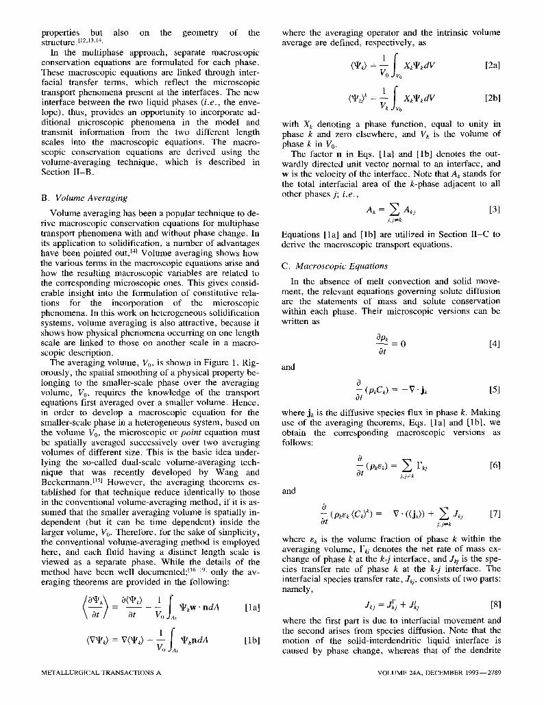
Also, the quadratic relation, Eq. [48], is employed as the growth model for the dendrite tips (i.e., Iv-~ (~) = f~ in Eq. [50]). The initial conditions for Eqs. [50], [62] through [64], and [75] are es = ed = 0, (C,) ~ = KC0, and C~ = ( C J = Co. This set of equations is numerically solved using the standard fourth-order Runge-Kutta method. Results are obtained for an A1-5 wt pct Si alloy, a cooling rate, 7", of 45 K s -I , and three different nuclei densities: n = 2.39 x 10¹¹, 2.39 x 10⁸ , and 2.39 x 10⁵ m -3, which correspond to final grain radii of 10 -4, 10 -3, and 10 -z m, respectively. It is assumed that nucleation occurs instantaneously at the liquidus temperature. The physical properties are taken from Reference 7.
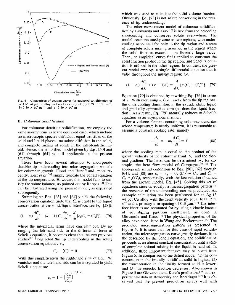
The predicted cooling curves near the recalescence stage are displayed in Figure 4, where the more exact solutions due to Rappaz and Thevoz tVl are shown as dashed lines. It is seen that the two predictions are indeed in close agreement, as they should. The minor difference for the case of n = 2.39 x 10 ~ m -3 is due to the fact that the present model utilizes an approximate analytical diffusion length, while Rappaz and Thevoz 's model tV~ calculates solute diffusion in the extradendritic liquid more accurately from a partial differential equa- tion. However, a comprehensive parametric study using different choices of the diffusion length leads to the con- clusion that the diffusion length is not a crucial factor in the present model/TM This, by the way, explains why the second model of Rappaz and Thevoz tSl employing the approximate diffusion length, Eq. [74], yields good results.
2 7 9 6 - - V O L U M E 24A, DECEMBER 1993 METALLURGICAL TRANSACTIONS A
0
O. 05
0.1
i 9.15 o
"~ 0.2
0.25
0. ~ / This work
x _ M
~ 0 0.'o2 o.'o4 o.'o~ 0/08 e.'l 0/12 0/14 o. IG �9 . . C + DLrnens~onless tame, ~ t
Ah
Fig. 4 - - C o m p a r i s o n of cooling curves for equiaxed solidification of an A1-5 wt pct Si alloy and nuclei density of (a) 2.39 • l0 II m 3, (b) 2.39 x 10⁸m 3, and (c ) 2.39 x 10⁵ m 3.
B. Columnar Solidification
For columnar dendritic solidification, we employ the same assumptions as in the equiaxed case, which include no macroscopic species diffusion, equal densities of the solid and liquid phases, no solute diffusion in the solid, and complete mixing of solute in the interdendritic liq- uid. Hence, the simplified model given by Eqs. [50] and [61] through [64] is still applicable in the present situation.
There have been several attempts to incorporate dendrite-tip undercooling into microsegregation models for columnar growth. Flood and Hunt Eg~ and, more re- cently, Kerr et al. f~l~ simply truncate the Scheil equation at the tip temperature. However, this model fails to sat- isfy the solute balance, as pointed out by Rappaz. TM This can be illustrated using the present model, as explained subsequently.
Summing up Eqs. [63] and [64] yields the following conservation equation (note that Ce is equal to the liquid concentration at the solid/liquid interface; see Eq. [58]):
d C e des d [e~(Ce - (CJ)] [76] (1 - es) ~ t + (K - 1) Ce d t - - dt
where the interracial terms have canceled out. By ar- ranging the left-hand side in the differential form of Scheil's equation, it becomes clear that the two previous studies [9'11~ neglected the tip undercooling in the solute conservation equation; i.e.,
Ce - (Ci) l~-" 0 [77]
With this simplification the right-hand side of Eq. [76] vanishes and the left-hand side can be integrated to yield Scheil's equation:
e, = 1 - [781
which was used to calculate the solid volume fraction. Obviously, Eq. [78] is not solute conserving in the pres- ence of tip undercooling.
The other more recent model of columnar solidifica- tion by Giovanola and Kurz El~ is free from the preceding shortcoming and conserves solute everywhere. The model treats the mushy zone as two regions, with under- cooling accounted for only in the tip region and a state of complete solute mixing assumed in the region where the solid fraction exceeds a sufficiently large value. Then, an empirical curve fit is applied to construct the solid fraction profile in the tip region, and Scheil's equa- tion is utilized in the other region. In contrast, the pres- ent model employs a single differential equation that is valid throughout the mushy region; i.e.,
(1 -- Es) d ~ e d - - "~- (K -- 1 ) C e = - - [ e l ( C e - (c i ) l )] [79] de, des
Equation [79] is obtained by rewriting Eq. [76] in terms of es. With increasing e, (i. e., away from the tip region), the undercooling diminishes in the extradendritic liquid and gradually approaches zero (so does the liquid frac- tion). As a result, Eq. [79] naturally reduces to Scheil's equation in an asymptotic manner.
For a volume element containing columnar dendrites whose temperature is nearly uniform, it is reasonable to assume a constant cooling rate, namely
dT d C e - m l - = J" [ 8 0 ]
dt dt
where the cooling rate is equal to the product of the growth velocity of the columnar front, V,, and the ther- mal gradient. The latter can be determined by, for ex- ample, the heat flow model of Campagna. t35'36~ The appropriate initial conditions to Eqs. [50], [62] through [64], and [80] are e, = t; d - - 0 , (Ci ) I = Co, and C e --
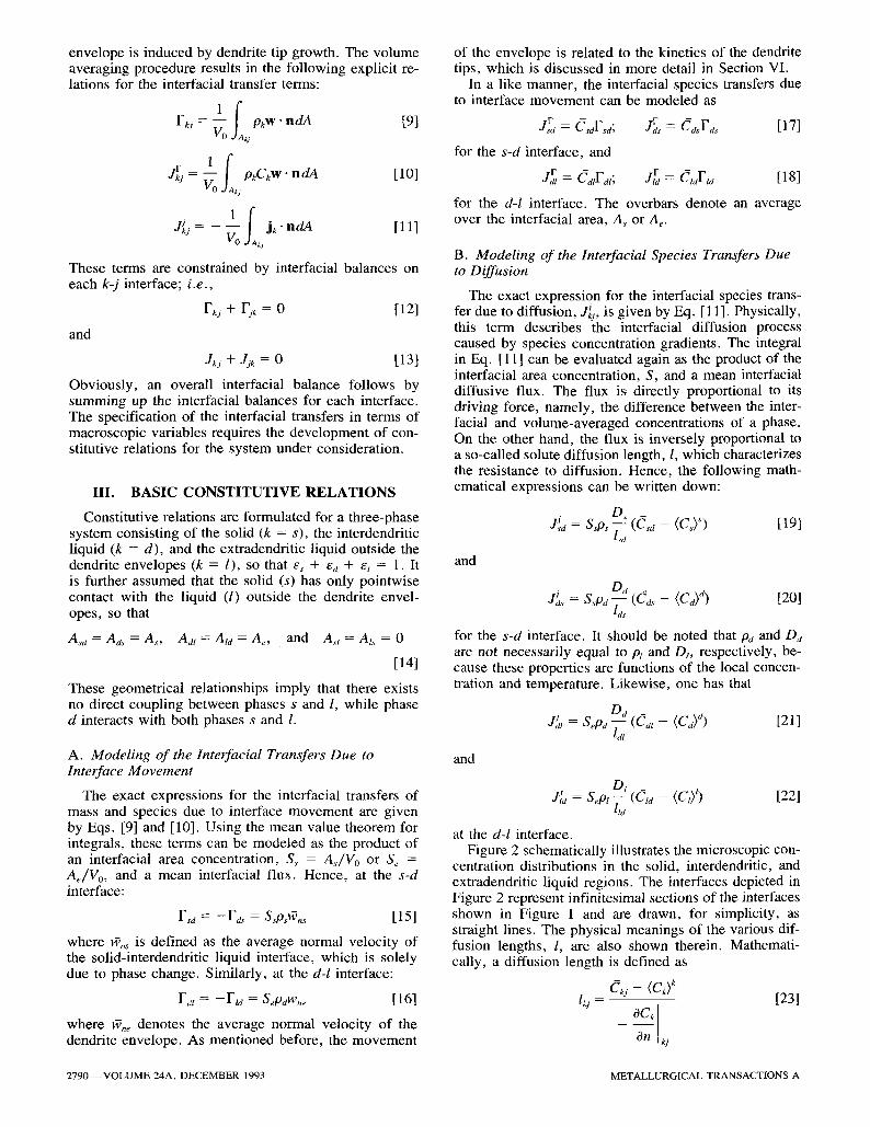
Co = f ( V 3 , respectively, with the last relation obtained from the growth model, Eq. [45]. Solving this set of equations simultaneously, a microsegregation pattern in the presence of tip undercooling can be predicted. An example calculation has been performed for an Ag-15 wt pct Cu alloy with the front velocity equal to 0.12 m s-1 and a primary arm spacing of 0 .3/xm. [37] The inter- face kinetics are accounted for by using a kinetic instead of equilibrium partition coefficient, as done in Giovanola and Kurz. tl~ The physical properties of the alloy have been listed in Wang and Beckermann. t33J The predicted microsegregation pattern is presented in Figure 5. It is seen that for this case of rapid solidifi- cation, the microsegregation curve greatly deviates from the described by the Scheil equation, and solidification proceeds at an almost constant concentration until a state of complete solutal mixing in the liquid is reached. In addition, three important features may be noted from Figure 5. In comparison to the Scheil model: (1) the con- centration in the initially solidified solid is higher, (2) the concentration in the finally formed solid is lower, and (3) the eutectic fraction decreases. Also shown in Figure 5 are Giovanola and Kurz's predictions t1~ and ex-
�9 - r [37] perimental data of Bendersky and Boettlnge . It is ob- served that the present prediction agrees well with
METALLURGICAL TRANSACTIONS A VOLUME 24A, DECEMBER 1993--2797
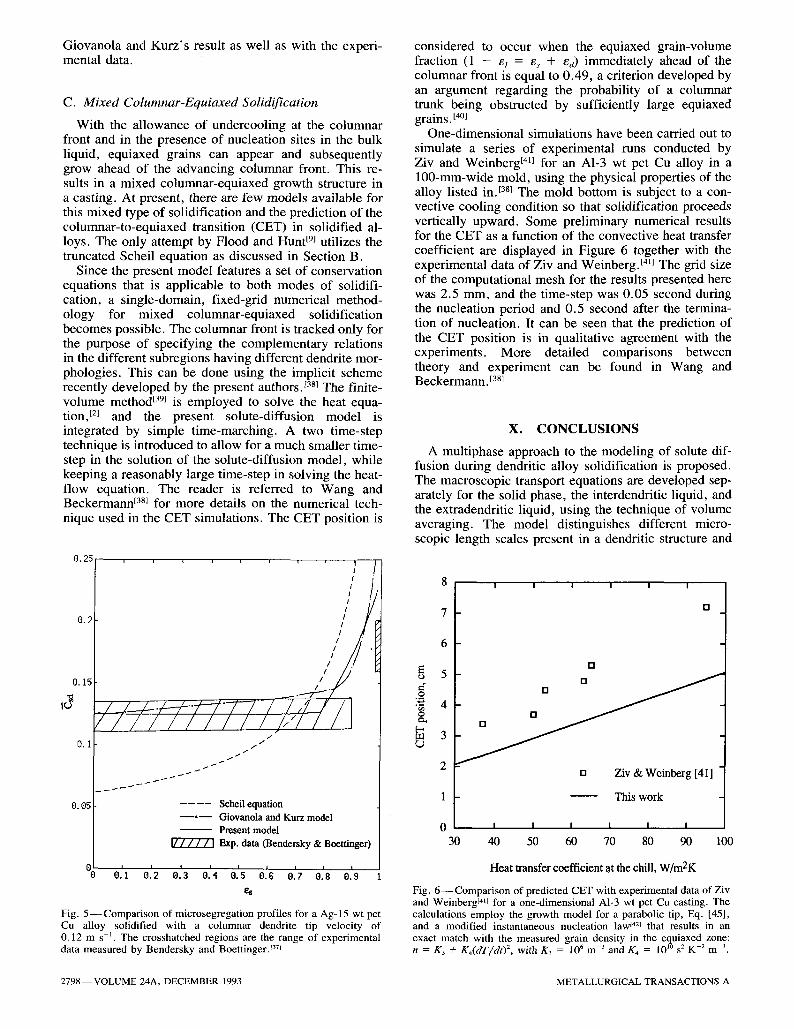
Giovanola and Kurz 's result as well as with the experi- mental data.
C. Mixed Columnar-Equiaxed Solidification
With the allowance of undercooling at the columnar front and in the presence of nucleation sites in the bulk liquid, equiaxed grains can appear and subsequently grow ahead of the advancing columnar front. This re- sults in a mixed columnar-equiaxed growth structure in a casting. At present, there are few models available for this mixed type of solidification and the prediction of the columnar-to-equiaxed transition (CET) in solidified al- loys. The only attempt by Flood and Hunt [9[ utilizes the truncated Scheil equation as discussed in Section B.
Since the present model features a set of conservation equations that is applicable to both modes of solidifi- cation, a single-domain, fixed-grid numerical method- ology for mixed columnar-equiaxed solidification becomes possible. The columnar front is tracked only for the purpose of specifying the complementary relations in the different subregions having different dendrite mor- phologies. This can be done using the implicit scheme recently developed by the present authors.j38[ The finite- volume method [39[ is employed to solve the heat equa- tion, [2[ and the present solute-diffusion model is integrated by simple time-marching. A two time-step technique is introduced to allow for a much smaller time- step in the solution of the solute-diffusion model, while keeping a reasonably large time-step in solving the heat- flow equation. The reader is referred to Wang and Beckermann [38~ for more details on the numerical tech- nique used in the CET simulations. The CET position is
0.25
0.2
8.15
10
0.1
O. 05
r
,/-/111/ 7//1 t
, I I I
i /
Seheil equation - - 0 - - Giovanola and Kurz model - - - Present model
[7"7"77"7"] Exp. data (Bendersky & Boettinger)
0 e:, 0:2 0:3 o:4 0:7 0:8 0:9' 1 es
Fig. 5 - Comparison of microsegregation profiles for a Ag-15 wt pct Cu alloy solidified with a columnar dendrite tip velocity of 0.12 m s -~. The crosshatched regions are the range of experimental data measured by Bendersky and BoettingerJ 37{
considered to occur when the equiaxed grain-volume fraction (1 - et = es + ea) immediately ahead of the columnar front is equal to 0.49, a criterion developed by an argument regarding the probability of a columnar trunk being obstructed by sufficiently large equiaxed grains. [40[
One-dimensional simulations have been carried out to simulate a series of experimental runs conducted by Ziv and Weinberg [411 for an A1-3 wt pct Cu alloy in a 100-mm-wide mold, using the physical properties of the alloy listed in. [38[ The mold bottom is subject to a con- vective cooling condition so that solidification proceeds vertically upward. Some preliminary numerical results for the CET as a function of the convective heat transfer coefficient are displayed in Figure 6 together with the experimental data of Ziv and Weinberg. t4~l The grid size of the computational mesh for the results presented here was 2.5 mm, and the time-step was 0.05 second during the nucleation period and 0.5 second after the termina- tion of nucleation. It can be seen that the prediction of the CET position is in qualitative agreement with the experiments. More detailed comparisons between theory and experiment can be found in Wang and Beckermann. [38]
X. C O N C L U S I O N S
A multiphase approach to the modeling of solute dif- fusion during dendritic alloy solidification is proposed. The macroscopic transport equations are developed sep- arately for the solid phase, the interdendritic liquid, and the extradendritic liquid, using the technique of volume averaging. The model distinguishes different micro- scopic length scales present in a dendritic structure and
I I I I I I
7
6
5
"8 4
3
[]
[]
[] Ziv & Weinberg [41]
1 This work
0 I I I I I I
30 40 50 60 70 80 90 100
Heat transfer coefficient at the chill, W/m2K
Fig. 6 - - Compa r i son of predicted CET with experimental data of Ziv and Weinberg t411 for a one-dimensional A1-3 wt pct Cu casting. The calculations employ the growth model for a parabolic tip, Eq. [45], and a modified instantaneous nucleation law {421 that results in an exact match with the measured grain density in the equiaxed zone: n = K 3 + K , ( d T / d t ) 2, with K3 = 106 m 3 and K4 = 10 l~ s 2 K -2 m 3.
2798--VOLUME 24A, DECEMBER 1993 METALLURGICAL TRANSACTIONS A

links the microscopic phenomena occurring on each length scale to the macroscopic equations. In particular, the model incorporates dendrite tip growth in the pres- ence of undercooling in the extradendritic liquid, as well as accounts for dendrite geometry, coarsening, and finite-rate solute diffusion in the solid. The model should lead to improved predictions of dendritic solidification and microstructure formation on the system scale. Furthermore, the present model consists of a single set of conservation equations for both equiaxed and colum- nar growth, thus providing a unified theoretical frame- work for both modes of solidification. Illustrative calculations have shown that the proposed model is suc- cessful in addressing a variety of phenomena, such as recalescence in equiaxed growth, dendrite tip under- cooling during rapid columnar solidification, and CET.
Efforts are currently underway to generalize the model to include melt convection and solid movement (for equiaxed grains) utilizing the same multiphase approach.
a
A As
Ae b C
C
cp d d~
D Iv J J
k 1 L ml
n n
Pe Pe,
r
R S Sv t
T T V
v~ Vo v,
N O M E N C L A T U R E
constant, in the A pendix interracial area, Am~ area of the solid/interdendritic liquid interface, m 2 area of the dendrite envelope, m 2 constant, in the Appendix constant, in the Appendix concentration of a chemical species, weight percent volumetric specific heat, J m - 3 K 1 microscopic length scale, m mean characteristic length or diameter of the solid phase, m mean characteristic diameter of the dendrite envelope, m diffusion coefficient, m 2 s -~ Ivantsov function species diffusion flux, kg m -2 s 1 interfacial species transfer rate per unit of volume, kg m - 3 s - 1
constants in the nucleation law, see Figure 6 species diffusion length, m macroscopic length scale, m liquidus line slope nuclei density, m 3 outwardly directed unit normal vector envelope Peclet number, "~neRJD~ solutal Peclet number at the dendrite tip, VtRt/2Dt radial coordinate radius, m interfacial area concentration, A J V o , m -1 specific interfacial area, Ak/Vk, m 1 time, s temperature, K cooling rate, K s -1 velocity, m s -1 volume of phase k, m 3
averaging volume, m 3
dendrite tip velocity, m s-
W
Wn X
X
interface velocity, m s- t normal interface velocity, ms -~ position vector phase function
Greek Symbols
a diffusion Fourier number, 4Dsty/h~ /3 a factor F interfacial mass transfer rate due to
interface movement (kg m - 3 S J) or Gibbs- Thomson coefficient (mK)
Ah volumetric latent heat of phase change, j m 3
volume fraction partition coefficient dendrite arm spacing, m density, kg m - 3
shape factor a field property a field property solutal supersaturation
E
/(
A P 4,
qt
f~
Subscripts
d interdendritic liquid e dendrite envelope f final dimension of the dendrite envelope j phase j k phase k kj pertinent to phase k on the k-j interface l extradendritic liquid m melting point of pure metal n normal direction o initial state r in the r-direction s solid t dendrite tip
Superscripts
j due to species gradients F due to interface movement - interfacial a rea - -averaged * effective or dimensionless
A P P E N D I X
Microscopic analysis of the diffusion lengths
Solid region
The modeling of the diffusion length in the solid is important for the prediction of finite-rate solute diffusion and, hence, microsegregation in a solidified alloy. For dendritic solidification, Ohnaka t341 has presented an el- egant model that gives good agreement with experimen- tal data and fits well into the framework of the present formulation. Following his procedure, the present deri- vation is based on a one-dimensional platelike dendrite arm geometry, as shown in Figure A 1. A parabolic con- centration distribution is assumed in the solid
C s = a + bx + cx 2 [A1]
METALLURGICAL TRANSACTIONS A VOLUME 24A, DECEMBER 1993--2799
The three coefficients are determined by the following boundary conditions
dCs - 0 at x = 0 (symmetry) [A2]
d r
Cs=Csd at x = d s / 2 [A3]
and the known volume-averaged concentration, (Cs) s, which can be calculated from
2 f d*/2 = Csdx [A4] {Cs>S
Using Eqs. [A2], [A3], and [A4], the concentration pro- file is found to be given by
Csa - C, 6 - ( d 2 / 4 - x 2) [A5]
(~sd- ( C y ds
With the definition of the diffusion length, Eq. [23], it is readily shown that
lsd = d J 6 [A6]
The mean diameter of the solid phase, ds, can be related to the secondary dendrite arm spacing, A2, and the vol- ume fraction G (Section IV). The derivation can be mod- ified for other dendrite arm geometries such as cylinders and spheres. The same result is obtained except for a change in the numerical factor of the order of unity.
Interdendritic liquid
For a dendrite envelope closely encompassing the den- drite arms, a similar analysis as that for the solid yields that the diffusion lengths in the interdendritic liquid, ljs and ld~, are proportional to the characteristic inter- dendritic spacing; i . e . ,
(/~2 -- d~) lds = ]31 - - [ A 7 ]
2
(& - ds) ldt = ]32 - - [A8]
2
where 131 and ]32 are constants of the order of unity. In recognition of Eq. [27], the two diffusion lengths given by Eqs. [A7] and [A8] suggest that
G and /d / ~ A 2 [A9]
Together with Eq. [A6], this implies that diffusion lengths in the interdendritic liquid and the solid are of the same order of magnitude. However, because the liq- uid mass diffusivity is typically several orders of mag- nitude larger than that of the solid, it is usually safe to assume that the interdendritic liquid is solutally well mixed and, thus, it is unimportant to accurately model finite-rate solute diffusion in the interdendritic liquid.
Extradendritic liquid
In contrast, one has to carefully model the diffusion length in the liquid outside the dendrite envelope in order to account for solutal undercooling of the liquid ahead
Fig. A I - - O n e - d i m e n s i o n a l , platelike model of a dendrite arm and illustration of the solid concentration profile.
of the dendrite tips. This is done here by assuming that: (1) the envelope is spherical with an equivalent radius Re and (2) solute diffusion is quasi-steady in the moving coordinate system fixed to the envelope surface, as il- lustrated in Figure A2.
(a) (b)
Fig. A 2 - - E q u i v a l e n t sphere model for species diffusion in the extra- dendritic liquid: (a) geometry and (b) concentration profile.
2800--VOLUME 24A, DECEMBER 1993 METALLURGICAL TRANSACTIONS A
The differential equation governing solute diffusion in the interdendritic liquid can now be written as
Vr - - -- r 2 d r r 2 d r d r /
The liquid around the envelope moves relative to the moving coordinate system at a radial velocity whose dis- tribution is obtained from the continuity equation as
2
Equation [A10], together with the velocity profile given by Eq. [A 11 ], admits a general solution of the form of
= ( w , e R e / D l r ) [A 12] Cl a + b exp - 2
By introducing a Peclet number that is based on the final equivalent radius, R I, of the dendrite envelope
vvneRf Pe - [A 13]
Dl
and a dimensionless radius
r* = r / R , . [A14I
Equation [A12] is recast into
] Cl = a + b exp (1 - et) 2/3 [A15]
where use has been made of the fact that R e / R f = (1 - El) ~/3. The constants a and b are determined by the following conditions
Cl = Cta, at r* = r* = (1 - 8l) 1/3 [A16]
( C i ) l = @ z f v 3 f l C i d V = - - r * 2 C l d r * [A17] l el 1 --8/) 1/3
With the concentration profile found, substitution into the definition of the diffusion length yields
l t J R I = - 1 - - - e x p [ - P e ( 1 - El) 1/3] Pe e~
1 el) 1/3 x2 exp x dx
[A18]
where x is a dummy variable of integration. The integral requires numerical evaluation.
This derivation for the liquid diffusion length can also be performed for cylindrical and Cartesian coordinate systems. Due to length limitations, only the final results are presented here:
1 ( 2 l la/Rf = - - 1 - - -
Pe e~ e x p [ - ~ ( 1 - El)I/2 In (1 -- Et)]
1 xexpr-Pe ) �9 l - - - - El) 1/2 In x] d x
k 1 --el) 1/2
[A19]
for a cylindrical envelope and
l~d/Rj. = - - 1 - - - [1 - exp (e/Pe)] Pe e~Pe
[A20]
for a platelike envelope. Equation [A18] is useful for equiaxed growth, while Eq. [A19] is applicable to the columnar case.
Last, it is worth noting that the diffusion lengths given by Eqs. [A18], [A19], and [A20] all share the property that
1 l t J R f <- - - [A21 ]
Pe
or alternatively,
Ol lld --< _ [A22]
W ne
A C K N O W L E D G M E N T S
This work was supported by the National Science Foundation under Grant No. CTS-8957149 and by the ALCOA Technical Center, Alcoa Center, PA.
R E F E R E N C E S
1. C. Beckermann and R. Viskanta: Appl. Mech. Rev., 1993, vol. 46, pp. 1-27.
2. M. Rappaz: Int. Mater. Rev., 1989, vol. 34, pp. 93-123. 3. V.R. Voller, M.S. Stachowicz, and B.G. Thomas: Materials
Processing in the Computer Age, TMS, Warrendale, PA, 1991. 4. J. Ni and C. Beckermann: Metall. Trans. B, 1991, vol. 22B,
pp. 349-61. 5. S. Ganesan and D.R. Poirier: Metall. Trans. B, 1990, vol. 21B,
pp. 173-81. 6. I. Dustin and W. Kurz: Z. Metallkd., 1986, vol. 77, pp. 265-73. 7. M. Rappaz and Ph. Thevoz: Acta Metall., 1987, vol. 35,
pp. 1487-97. 8. M. Rappaz and Ph. Thevoz: Acta Metall., 1987, vol. 35,
pp. 2929-33. 9. S.C. Flood and J.D. Hunt: Appl. Sci. Res., 1987, vol. 44,
pp. 27-42. 10. B. Giovanola and W. Kurz: Metall Trans. A, 1990, vol. 21A,
pp. 260-63. 11. R.C. Kerr, A .W. Woods , M.G. Worster, and H.E. Huppert:
J. Fluid Mech., 1990, vol. 217, pp. 331-48. 12. N. Wakao and J.M. Smith: Chem. Eng. Sci., 1962, vol. 17,
pp. 825-34. 13. O.A. Plumb and S. Whitaker: in Dynamics of Fluids in
Hierarchical Porous Media, J.H. Cushman, ed., Academic Press, London, 1990, pp. 97-148.
14. M. Kaviany: Principles of Heat Transfer in Porous Media, Springer-Verlag, New York, NY, 1991.
15. C.Y. Wang and C. Beckermann: Int. J. Multiphase Flow, 1993, vol. 19, pp. 397-407.
16. D.A. Drew: Annu. Rev. Fluid Mech., 1983, vol. 15, pp. 261-91.
METALLURGICAL TRANSACTIONS A VOLUME 24A, DECEMBER 1993--2801
17. S.M. Hassanizadeh and W.G. Gray: Adv. Water Resour., 1979, vol. 2, pp. 131-44.
18. S.M. Hassanizadeh and W.G. Gray: Adv. Water Resour., 1979, vol. 2, pp. 191-208.
19. S.M. Hassanizadeh and W.G. Gray: Adv. Water Resour., 1980, vol. 3, pp. 25-41.
20. M. Rappaz and V.R. Voller: Metall. Trans. A, 1990, vol. 21A, pp. 749-53.
21. D.R. Poirier, P.J. Nandapurkar, and S. Ganesan: Metall. Trans. B, 1991, vol. 22B, pp. 889-900.
22. S.P. Marsh and M.E. Glicksman: in Modeling of Casting, Welding and Advanced Solidification Processes V1, T.S. Piwonka, V. Voller, and L. Katgerman, eds., TMS, Warrendale, PA, 1993, pp. 55-62.
23. M.E. Glicksman, R.N. Smith, S.P. Marsh, and R. Kuklinski: Metall. Trans. A, 1992, vol. 23A, pp. 659-67.
24. R.T. DeHoff and F.N. Rhines: Quantitative Microscopy, McGraw-Hill, New York, NY, 1968.
25. R.B. Bird, W.E. Stewart, and E.N. Lightfoot: Transport Phenomena, John Wiley, New York, NY, 1960, p. 167.
26. T.Z. Kattamis, J.C. Coughlin, and M.C. Flemings: Trans. TMS- A1ME, 1967, vol. 239, pp. 1504-11.
27. S.P. Marsh, M.E. Glicksman, L. Meloro, and K. Tsutsumi: in Modeling and Control of Casting and Welding Processes IV, A.F. Giame and G.J. Abbashian, eds., TMS, Warrendale, PA, 1988, pp. 15-23.
28. M. Avrami: J. Chem. Phys., 1940, vol. 8, pp. 212-24. 29. G.R. Speich and R.M. Fisher: in Recrystallization, Grain
Growth and Textures, Margolin, H., ed., ASM, Metals Park, OH, 1966, pp. 563-98.
30. S. Ahuja, C. Beckermann, R. Zakhem, P.D. Weidman, and H.C. deGroh III: in Micro/Macro Scale Phenomena in Solidification, C. Beckermann, L.A. Bertram, S.J. Pien, and R.E. Smelser, eds., ASME, New York, NY, 1992, pp. 85-91.
31. W. Kurz and D.J. Fisher: Fundamentals of Solidification, Trans. Tech Publications, Aedermannsdorf, Switzerland, 1989.
32. J. Lipton, M.E. Glicksman, and W. Kurz: Mater. Sci. Eng., 1984, vol. 65, pp. 57-63.
33. C.Y. Wang and C. Beckerrnann: Mat. Sci. Eng. A, 1993, in press.
34. I. Ohnaka: Trans. Iron Steel Inst. Jpn., 1986, vol. 26, pp. 1045-51.
35. A.J. Campagna: Ph.D. Thesis, Massachusetts Institute of Technology, Cambridge, MA, 1970.
36. M.C. Flemings: Metall. Trans. A, 1991, vol. 22A, pp. 957-81. 37. L.A. Bendersky and W.J. Boettinger: in Rapidly Quenched
Metals, S.S. Warlimont, ed., 1985, vol. 1, pp. 887-90. 38. C.Y. Wang and C. Beckermann: Metall. Trans. A, 1993,
vol. 24A, in press. 39. S.V. Patankar: Numerical Heat Transfer and Fluid Flow,
Hemisphere Publishing Corp., New York, NY, 1980. 40. J.D. Hunt: Mater. Sci. Eng., 1984, vol. 65, pp. 75-83. 41. I. Ziv and F. Weinberg: Metall. Trans. B, 1989, vol. 20B,
pp. 731-34. 42. D.M. Stefanescu, G. Upadhya, and D. Bandyopahyoy: Metall.
Trans. A, 1990, vol. 21A, pp. 997-1005.
2802--VOLUME 24A, DECEMBER 1993 METALLURGICAL TRANSACTIONS A