a multilayer-coated diffraction-grating device for polarized and unpolarized neutron interferometry
Post on 19-Sep-2016
212 views
TRANSCRIPT
20
J. Appl. Cryst. (1995). 28, 20-25
A Multilayer-Coated Diffraction-Grating Device for Polarized and Unpolarized Neutron Interferometry
BY M . M,~AZA AND B. PARDO
Institut d' Optique Th~orique et Appliqu~e, BCttiment 503, Universit~ Paris Sud, Orsay, France
(Received 16 September 1992; accepted 4 July 1994)
Abstract
This work is devoted to a new generation of cold- neutron interferometers based on bidimensional diffrac- tion. The use of multilayer coatings in the classical Ioffe difffraction-grating neutron interferometer is pro- posed. This interferometer combines the properties of two periodic structures, namely the dispersion by a diffraction grating and the high reflectivity ensured by the multilayer coating. All the cold-neutron interferom- eter devices (two diffraction gratings and two mirrors) must be multilayered with Ni-Ti or Fe-Ge for unpo- larized or polarized neutron interferometry experiments, respectively. The computed results, giving the charac- teristics of the multilayer-coated amplitude diffraction grating are discussed within a kinematic model. An Ni-Ti multilayered amplitude diffraction grating for use at A = 5/~ is presented as an example.
1. Introduction
The technique of neutron interferometry with wave- lengths on the angstrom scale has developed steadily since it was established more than 18 years ago (Rauch, Treimer & Bonse, 1974; Rauch & Petraschek, 1978). The theoretical aspects have been rigorously developed in numerous articles (Bonse, 1979; Ranch, 1979). Neutron interferometry has been established as an almost ideal tool for experimental tests of the foundations of quan- tum mechanics. These tests include: the historic direct experimental confirmation of the 47r periodicity of spinor wave functions (Rauch, Zeilinger, Badurek, Wilting, Bauspiess & Bonse, 1975), the quantum principles of linear superposition of fermion spin states (Summham- mer, Badurek, Rauch, Kischko & Zeilinger, 1983), the observation of the Aharonov-Casher topological phase shift (Cimmino, Opat, Klein, Kaiser, Werner, Arif & Clothier, 1989) and the observation of the gravitation- ally induced quantum interference due to the earth's rotation (Collela, Overhauser & Werner, 1975). These unique fundamental experiments, amongst the highlights of modern physics, contribute strongly to give a real- istic proof of the Schr6dinger-de Broglie wave-matter formalism.
As in electromagnetic interferometry (Fran~on, 1967), a neutron interferometer consists of three components: a beam splitter, a mirror and an analyzer. There are two
© 1995 International Union of Crystallography Printed in Great Britain - all rights reserved
kinds of neutron interferometers, the Hart-Bonse silicon perfect crystal (Bonse, 1979) and the Ioffe diffraction grating (Ioffe, 1983; Ioffe, Zabijakin & Drabkin, 1985). They differ from each other according to the manner in which the splitting of the incident unpolarized neutron beam into two coherent beams is performed. Both of them correspond to the so-called Mach-Zehnder classi- cal interferometer.
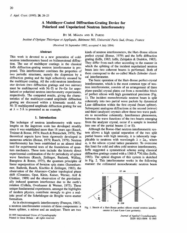
The basic operation of the Hart-Bonse perfect-crystal interferometer, which is the most common type of neu- tron interferometer, consists of an arrangement of three plane-parallel crystal plates cut from a monolithic block of perfect silicon with high geometrical precision (Fig. 1). The incident monochromatic neutron beam is split coherently into two partial wave packets by dynamical Laue diffraction within the first crystal (beam splitter). Subsequent analogous diffractions at the second (mirror) and third (analyzer) crystals allow these two wave pack- ets to recombine coherently. Interference phenomena, between the wave functions of the two beams emerging from the analyzer crystal, occur if a sample is inserted into one of the partial beams (I or II).
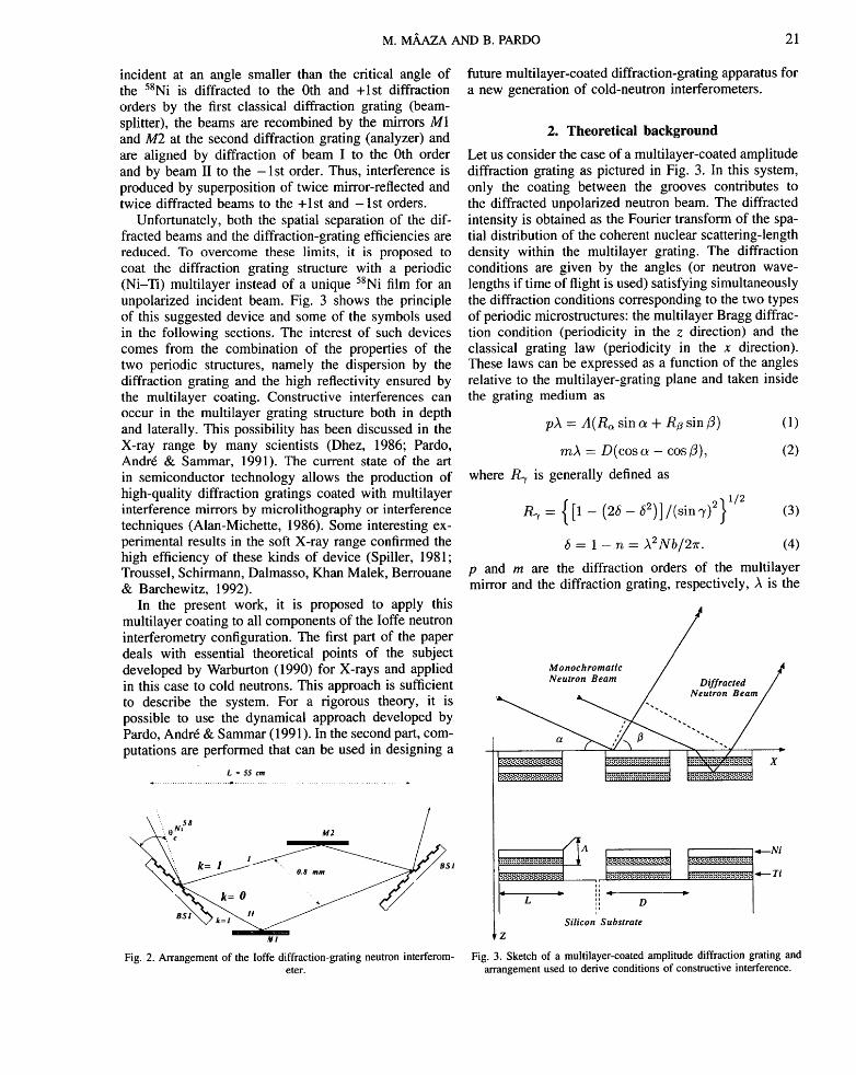
Although the Bonse-Hart neutron interferometric sys- tem allows a high spatial separation of the two split partial beams with high intensity, it is inherently inap- plicable to neutrons with wavelength A > 2ac, where ac is the silicon crystal lattice parameter. To overcome this limit for cold and ultra cold neutron interferometry, Ioffe suggested a symmetrical scheme using classical diffraction gratings coated with a 1500/~ 58Ni film (Ioffe, 1983). The optical diagram of this system is sketched in Fig. 2. This interferometer works in the following manner: the collimated monochromatic neutron beam
12 cm
0 Y
Si 220
Fig. 1. Sketch of a Hart-Bonse perfect silicon crystal neutron interfer- ometer in Laue-Laue-Laue geometry.
Journal of Applied Crystallography ISSN 0021-8898 © 1995
M. M,~,AZA AND B. PARDO 21
incident at an angle smaller than the critical angle of the 58Ni is diffracted to the 0th and +lst diffraction orders by the first classical diffraction grating (beam- splitter), the beams are recombined by the mirrors MI and M2 at the second diffraction grating (analyzer) and are aligned by diffraction of beam I to the 0th order and by beam II to the -1s t order. Thus, interference is produced by superposition of twice mirror-reflected and twice diffracted beams to the +lst and -1s t orders.
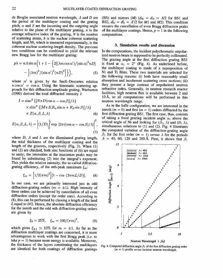
Unfortunately, both the spatial separation of the dif- fracted beams and the diffraction-grating efficiencies are reduced. To overcome these limits, it is proposed to coat the diffraction grating structure with a periodic (Ni-Ti) multilayer instead of a unique 58Ni film for an unpolarized incident beam. Fig. 3 shows the principle of this suggested device and some of the symbols used in the following sections. The interest of such devices comes from the combination of the properties of the two periodic structures, namely the dispersion by the diffraction grating and the high reflectivity ensured by the multilayer coating. Constructive interferences can occur in the multilayer grating structure both in depth and laterally. This possibility has been discussed in the X-ray range by many scientists (Dhez, 1986; Pardo, Andre & Sammar, 1991). The current state of the art in semiconductor technology allows the production of high-quality diffraction gratings coated with multilayer interference mirrors by microlithography or interference techniques (Alan-Michette, 1986). Some interesting ex- perimental results in the soft X-ray range confirmed the high efficiency of these kinds of device (Spiller, 1981; Troussel, Schirmann, Dalmasso, Khan Malek, Berrouane & Barchewitz, 1992).
In the present work, it is proposed to apply this multilayer coating to all components of the Ioffe neutron interferometry configuration. The first part of the paper deals with essential theoretical points of the subject developed by Warburton (1990) for X-rays and applied in this case to cold neutrons. This approach is sufficient to describe the system. For a rigorous theory, it is possible to use the dynamical approach developed by Pardo, Andre & Sammar (1991). In the second part, com- putations are performed that can be used in designing a
L = 55 c m
0f' / """ I
k=O
Fig. 2. Arrangement of the Ioffe diffraction-grating neutron interferom- eter.
future multilayer-coated diffraction-grating apparatus for a new generation of cold-neutron interferometers.
2. Theoretical background
Let us consider the case of a multilayer-coated amplitude diffraction grating as pictured in Fig. 3. In this system, only the coating between the grooves contributes to the diffracted unpolarized neutron beam. The diffracted intensity is obtained as the Fourier transform of the spa- tial distribution of the coherent nuclear scattering-length density within the multilayer grating. The diffraction conditions are given by the angles (or neutron wave- lengths if time of flight is used) satisfying simultaneously the diffraction conditions corresponding to the two types of periodic microstructures: the multilayer Bragg diffrac- tion condition (periodicity in the z direction) and the classical grating law (periodicity in the x direction). These laws can be expressed as a function of the angles relative to the multilayer-grating plane and taken inside the grating medium as
pA = A ( R ~ s i n a + R~ sin/3) (1)
mA = D(cos a - cos/3), (2)
where R.y is generally defined as
= }1/2 P~ { [1 - (26 - 52)] /(sin T) 2 (3)
6 = 1 - n = A 2 N b / 2 ~ r . (4)
p and m are the diffraction orders of the multilayer mirror and the diffraction grating, respectively, A is the
Monochromatic / 4 4 .. Neutron / NDiffractedBea m /
t D
Silicon Substrate Z
Fig. 3. Sketch of a multilayer-coated amplitude diffraction grating and arrangement used to derive conditions of constructive interference.
22 MULTILAYER-COATED DIFFRACTION GRATING
de Broglie associated neutron wavelength, A and D are the period of the multilayer coating and the grating pitch, a and/3 are the incoming and the outgoing angle relative to the plane of the multilayer grating, n is the average refractive index of the grating, N is the number of scattering atoms, b is the nuclear coherent scattering length, and Nb, which is measured experimentally, is the coherent nuclear scattering-length density. The previous two conditions can be combined to yield the relevant new Bragg law for the multilayer grating:
pA = n A s i n a ( 1 + 1 - { 2 [ ( A m c o s a ' ) / ( s i n a ) 2 n D ]
- [ ( A m ) ~ / ( s i n a ' ) 2 ( n D ) ~ ] } ) , (5)
where a ' is given by the Snell-Descartes relation n cos a ' = cos a. Using the kinematic scattering ap- proach for this diffraction-amplitude grating, Warburton (1990) derived the total diffracted intensity I:
I = s i n c ~ { [ N ~ D ( c o s a - cos~)]/A}
x sinc 2 {[MTrA(R,~s ina + R~ sin/3)]/A}
x Z ( a , fly L, A) (6)
_ L 12 Z(o~,/3, L , A ) = ( 1 / D ) f e x p [2~-i (cosa-cos/3) /A]
(7)
where D, A and L are the illuminated grating length, the total thickness of the multilayer coating and the length of the grooves, respectively (Fig. 3). When (1) and (2) are checked, both sinc functions of (6) are equal to unity; the intensities at the maximum peaks may be found by substituting (2) into the integral's exponent. This yields the relative intensity, the so-called diffration- grating efficiency, of the ruth-peak maximum ~m:
[1/2(~'m) 2] [1 - cos (27rmL/D)] . (8)
In our case, we are primarily interested just in odd diffraction-grating orders (m = -t-1). High intensity of these orders can be achieved by cancellation of all even diffraction orders (except the order zero). According to (8), this can be performed by chosing a length of the land L equal to D/2. Hence, the absolute diffraction efficiency for the zeroth and the odd mth difffraction-grating orders are given by
~0 = 257O, ~,~ = 100/(Trm) 9, ( 9 )
which gives ~+1 "" 1070 for m = +1. As far as the diffraction multilayer coatings are concerned, it is more advantageous to work with the first Bragg peak (i.e. to take p = 1) because more energy is available. Moreover, the thickness of the layers constituting the multilayers are identical for both coatings of diffraction gratings
(BS) and mirrors (M) (dNi : dTi : A/2 for BS1 and BS2, d{~i = d~i = A'/2 for M1 and M2). This condition ensures the cancellation of even Bragg diffraction peaks of the multilayer coatings. Hence, p - 1 in the following computations.
3. S i m u l a t i o n r e s u l t s a n d d i s c u s s i o n
In the computations, the incident polychromatic unpolar- ized neutron beam is supposed to be perfectly collimated. The grazing angle at the first diffraction grating BS1 is fixed at oq = 2 ° (Fig. 4). As underlined before, the multilayer coating is made of a superposition of Ni and Ti films. These two materials are selected for the following reasons: (i) both have reasonably small absorption and incoherent scattering cross sections; (ii) they present a large contrast of unpolarized neutron refractive index. Generally, in neutron research reactor facilities, high neutron flux is available between 2 and 10•, so all computations will be performed in this neutron wavelength range.
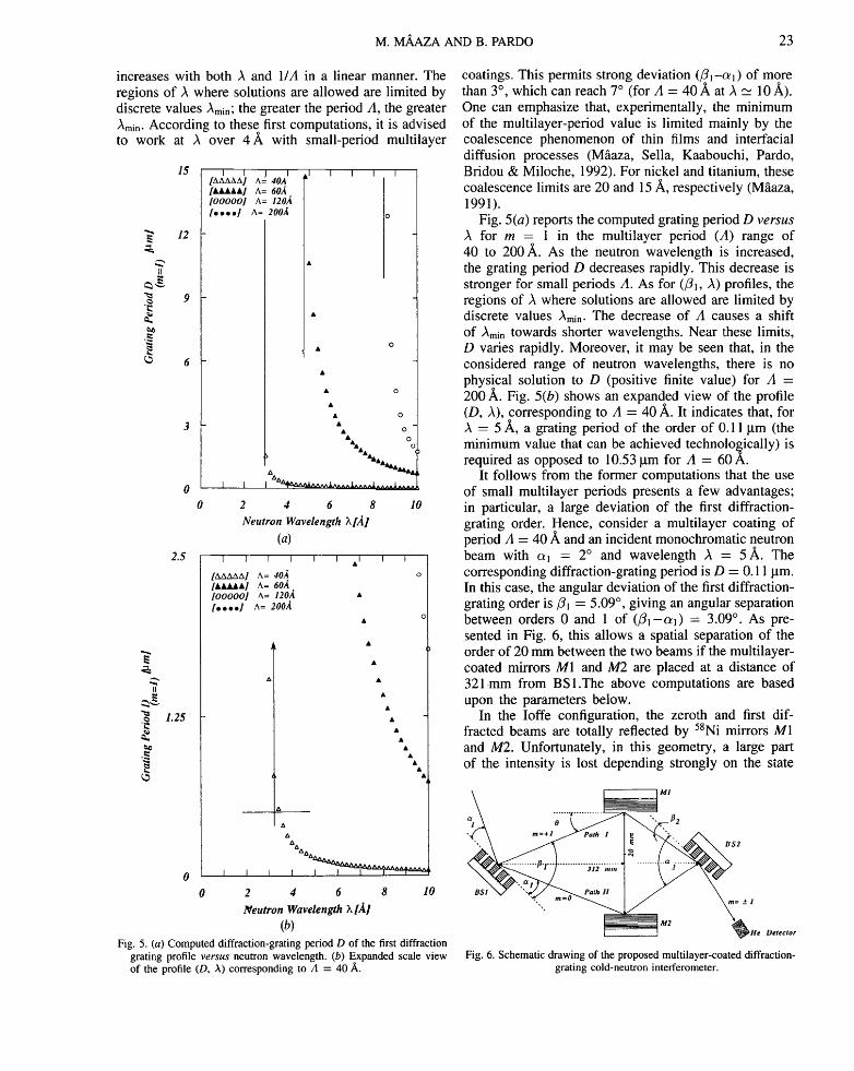
As in the Ioffe configuration, we are interested in the zeroth (m = 0) and first (m = 1) orders diffracted by the first diffraction grating BS 1. The first case, thus, consists of taking a fixed grazing incident angle oq above the critical angle of Ni and looking for (/31, A)and (D, A), simultaneous solutions to (1) and (2). Fig. 4 illustrates the computed variation of the diffraction-grating angle /31 for the first order (m = 1) versus A for the periods A = 40, 60, 120 and 200~. First, it shows that /31
12 i i i A
/AAAAM A= 40A A
[000001 A= 120A 4 [0 .,0 01 A= 200A ,,
&& ..~ .9 ++
II A
AA &&
6 A A &&
A jl+& && e a+ ' & &Jl, JkA
"~ A & &&
3 AA A ~ AA ~ _~1
A && 0000~ & • 00 I.:' , '"I ~ooOO°°
aa 0000'1 @ ~.~ _&A [ ~0000 l .@@..I0
=~ t , " I Lo~ ~ , L - - . ~ " "
1 5.5 10
Neutron Wavelength ~ [A]
Fig. 4. Computed diffraction angle ~1 of the first diffraction grating order (m = 1) profile versus incident neutron wavelength.
M. MAAZA AND B. PARDO 23
increases with both A and 1/A in a linear manner. The regions of A where solutions are allowed are limited by discrete values/~min; the greater the period A, the greater /~min. According to these first computations, it is advised to work at A over 4 A with small-period multilayer
2.5
.~ 1.25
g,
15
12
/AAAAAI 40A I l t t t t t l A= 60A 1ooooo1 A= 120A [ . . . . 1 A= 200A
I I I I
o
• O
• o
° o
% I I ~ ^ ^ ~ , ^ , , ~ . . . . 1 . . . .
2 4 6 8 I0
Neutron Wavelength ?~ [A]
(a) I J 1 I I I A I I I
[AAAAA] A= 40A IA~UkAA1 A= 60A. [00000] A= 120A [ o • . . 1 A= 200A
A A
A&
0 J f t
0 2 4 6 8 10
Neutron Wavelength h [A] (b)
Fig. 5. (a) Computed diffraction-grating period D of the first diffraction grating profile versus neutron wavelength. (b) Expanded scale view of the profile (D, A) corresponding to A = 40 A,.
coatings. This permits strong deviation (il~-al) of more than 3 °, which can reach 7 ° (for A = 40 A, at A _~ 10/~). One can emphasize that, experimentally, the minimum of the multilayer-period value is limited mainly by the coalescence phenomenon of thin films and interfacial diffusion processes (Mfiaza, Sella, Kaabouchi, Pardo, Bridou & Miloche, 1992). For nickel and titanium, these coalescence limits are 20 and 15 A,, respectively (M~aza, 1991).
Fig. 5(a) reports the computed grating period D versus A for m - 1 in the multilayer period (A) range of 40 to 200 ]~. As the neutron wavelength is increased, the grating period D decreases rapidly. This decrease is stronger for small periods A. As for (ill, A) profiles, the regions of A where solutions are allowed are limited by discrete values Amin. The decrease of A causes a shift of )~min towards shorter wavelengths. Near these limits, D varies rapidly. Moreover, it may be seen that, in the considered range of neutron wavelengths, there is no physical solution to D (positive finite value) for A - 200 A,. Fig. 5(b) shows an expanded view of the profile (D, A), corresponding to A = 40 A. It indicates that, for A = 5 A, a grating period of the order of 0.11 ~tm (the minimum value that can be achieved technologically) is required as opposed to 10.53 lam for A = 60 A.
It follows from the former computations that the use of small multilayer periods presents a few advantages; in particular, a large deviation of the first diffraction- grating order. Hence, consider a multilayer coating of period A = 40 A and an incident monochromatic neutron beam with a l = 2 ° and wavelength A = 5]k. The corresponding diffraction-grating period is D = 0.11 l.tm. In this case, the angular deviation of the first diffraction- grating order is il~ = 5.09 °, giving an angular separation between orders 0 and 1 of ( i l - a l ) = 3.09 °. As pre- sented in Fig. 6, this allows a spatial separation of the order of 20 mm between the two beams if the multilayer- coated mirrors M1 and/142 are placed at a distance of 321ram from BS1.The above computations are based upon the parameters below.
In the Ioffe configuration, the zeroth and first dif- fracted beams are totally reflected by 58Ni mirrors M1 and M2. Unfortunately, in this geometry, a large part of the intensity is lost depending strongly on the state
. . . . . . -¢ . . . . . . . . . . . , 1] 0 " ' . 2
2
B S l . ± 1
Fig. 6. Schematic drawing of the proposed multilayer-coated diffraction- grating cold-neutron intefferometer.
24 MULTILAYER-COATED DIFFRACTION GRATING
of the surface (flatness, roughness). To minimize this effect, the use of multilayer coating is also required for the mirrors M1 and M2. Moreover, the use of multilayers allows a reduction in the spatial extension in region 2 of the interferometer (Fig. 6). If the dispersion relation is neglected, the period A' of these mirror multilayer coatings is given by A' = A/2sin 0, where 0 is the grazing angle at the surface of the multilayer coating. As will be shown, this angle is related to the angular parameters oq, ill, a2 and il2 of the tWO multi!ayer-coated diffraction gratings. To find this relation, let us recall that in the Ioffe configuration, at the second diffraction grating BS2, the beams I (order 1 for BS1) and II (order 0 for BS1) are diffracted at 0th and - l s t orders, respectively. If the BS2 characteristics are identical to those of BS1, for diffraction-grating order - 1 , provided that Ra2 = Rfl2 = 1 (dispersion relation is neglected), the incident and diffracted angles a2 and t 2 are given, respectively, by
o~. = arcsin{ ()~/2)[(m/D) 2 + (p/A)2]~l 2}
+ arctan ( - m A / p D ) (10)
~2 = arcsin{ ()~/2)[(m/D) 2 + (p/A)2] t/2}
- arctan ( - m A / p D ) . (11)
Thus, for ~ = 5 A, D = 0.11 l.tm, A = 40/~., m = - 1 , p = 1, a2 and il2 are equal to 5.67 and 1.50 ° , respectively. To recombine spatially the orders - 1 and +1, simple geometrical considerations enable one to obtain the equation
40 = (a2 - 12) + (ill -- O~1). (12)
For the previous values, 0 is equal to 1.82 °. It follows from this that a multilayer mirror period of A' = 79/1, is required (with d~i = d~ "-' 40,~). According to these results, one can conclude that it is possible to make an unpolarized cold-neutron intefferometer in Ioffe configuration whose components are all coated by (Ni-Ti) multilayers. The number of the (Ni-Ti) bilayers of the coatings can be adjusted easily to obtain neutron Bragg reflectivities of over 98% (M~za, 1991). These kinds of new intefferometers will allow both high spatial separation and high diffraction efficiencies (less intensity loss) of the two coherent beams. The theoretical values of ~0 = 25% and ~±1 = 10% can be reached. The characteristics of an interferometer working at A = 5/~ are given in Table 1.
Until now, the discussion was mainly on the use of the multilayer (Ni-Ti) coated diffraction grating interferom- eter with unpolarized cold neutrons. To achieve polarized neutron interferometry with the proposed configuration, without any additional flipping systems, multilayer films of magnetic-nonmagnetic materials are sufficient. As for the (Ni-Ti) multilayer coatings, the materials used must present large coherent magnetic scattering cross sections for one spin state (i.e. the matching condi-
Table 1. Characteristics o f an (Ni-Ti) multilayer-coated diffraction-grating interferometer working at )~ = 5 ,~
with unpolarized cold neutrons
First diffraction Second diffraction gating BSI Mirrors M1 and M2 grating BS2
cq = 2.00 ° 0 = 1.82 ° c~2 = 2.00 ° 31 = 5.09 ° •2 = 2. 000 D=0.11 ~m D= 0.11 ~m L = 0.055 ~rn L = 0.055 tun m=+l m=0 A = 40A A = 79/~ A = 40/~ dNi = dTi = 20/~ d/~ i = d~ = 40/~ dNi = dTi = 20/~ p = l p t = l p = l
tion for one spin state is required). This important condition ensures high polarization. Thus, taking into account these criteria, (Fe-Ge) multilayer coatings can be used. The polarization of the incident neutron beam must be achieved totally at the first multilayer-coated diffraction grating BS 1. From a practical point of view, taking into account the preparation problems, the (Ni-Ti) and (Fe--Ge) multilayer coating must be deposited on prepared silicon grating substrates (Mailly & Guerin, 1992).
4. Concluding remarks
Firstly, we proposed the use of multilayer coatings in Ioffe diffraction-grating neutron interferometry for both polarized and unpolarized cold neutrons. The interest in such devices comes from the combination of the properties of two periodic structures, namely the dis- persion by the classical diffraction grating and the high reflectivity ensured by the multilayer coating. Secondly, characteristics of such an interferometer working at )t = 5/~ with unpolarized cold neutrons are given. High levels of performance are theoretically possible with this new generation of neutron interferometers and work is under way to achieve this goal experimentally.
The authors are indebted to Drs D. Mailly and P. Guerin from Centre National d'Etudes de Trlrcommuni- cation of Bagneux, Professor R. Barchewitz and Dr J. M. Andr6 from Pierre-Marie Curie University for many useful discussions and Miss I. Granger for her invaluable help.
References
ALAN-MICHETrE, G. (1986). Optical Systems for Soft X-rays, edited by G. ALAN-MICHEITE, pp. 147-157. New York/London: Plenum Press.
BONSE, U. (1979). Neutron Interferometry, edited by U. BONSE & H. RAUCH, pp. 3-33. Oxford Science Publications.
CIMMINO, A., OPAT, G. I., KLEIN, A. G., KAISER, L., WERNER, • S . A . , ARIF, M. &: CLOTHIER, R. (1989). Phys. Rev. Lett. 63,
380-383. COLLELA, R., OVERHAUSER, A. W. & WERNER, S. A. (1975).
Phys. Rev. Lett. 34, 1472-1474.
M. M,~,AZA AND B. PARDO 25
DHEZ, P. (1986). J. Phys. (Paris) Colloq. C6, Suppl. 10, 47, 267-275.
FRAN(~ON, M. (1967). Advanced Optica Techniques, edited by A. C. S. VAN HEEL, pp. 23-70. Amsterdam: North-Holland.
IOFFE, A. I. (1983). Nucl. Instrum. Methods, 204, 565. IOFFE, A. I., ZAB1JAKIN, V. & DRABKIN, G. (1985). Phys. Lett.
A, 111, 373-375. MAAZA, M. (1991). Thesis, Pierre-Made Curie Univ., Pads,
France. M,~AZA, M., SELLA, C., KAABOUCHI, M., PARDO, B., BRIDOU,
F. & MILOCHE, M. (1992). Neutron Optical Devices & Applications. SPIE Proc. No. 1738, pp. 166-175.
MAILLY, D. & GUERIN, H. (1992). Private communication. PARDO, B., ANDRI~, J. M. & SAMMAR, A. (1991). J. Optics
(Paris), 22, 141-153. RAUCH, H. (1979). Neutron lnterferometry, edited by U. BONSE
& H. RAUCH, pp. 162-193. Oxford Science Publications.
RAUCH, H. & PETRASCHEK, D. (1978). Neutron Diffraction, edited by H. DACHS, p. 303. Berlin: Springer.
RAUCH, H., TREIMER, W. & BONSE, U. (1974). Phys. Lett. A, 47, 369-371.
RAUCH, H., ZEILINGER, A., BADUREK, G., WILFING, A., BAUSPIESS, W. & BONSE, U. (1975). Phys. Lett. A, 54, 425-427.
SPILLER, E. (1981). Low Energy X-ray Diagnostics, AIP Conf. Proc. No. 75, edited by D. T. ATWOOD & B. L. HENKE, pp. 124-130.
SUMMHAMMER, J., BADUREK, G., RAUCH, n., KISCHKO, U. & ZEILINGER, A. (1983). Phys. Rev. A27, 2523-2532.
TROUSSEL, P., SCHIRMANN, D., DALMASSO, J. M., KHAN MALEK, C., BERROUANE, H. & BARCHEWITZ, R. (1992). Rev. Sci. Instrum. 63, 2125-213 I.
WARBURTON, W. K. (1990). Nucl. Instrum. Methods, A291, 291-297.