a model-driven engineering approach for the usability … · a model-driven engineering approach...
TRANSCRIPT
J. Gulliksen et al. (Eds.): EIS 2007, LNCS 4940, pp. 140–157, 2008.
A Model-Driven Engineering Approach for the Usability of Plastic User Interfaces
Jean-Sébastien Sottet, Gaëlle Calvary, Joëlle Coutaz, and Jean-Marie Favre
Université Joseph Fourier, 385 rue de la Bibliothèque, BP 53, 38041 Grenoble Cedex 9, France
{Jean-Sebastien.Sottet,Gaelle.Calvary,Joelle.Coutaz, Jean-Marie.Favre}@imag.fr
Abstract. Plastic User Interfaces (UI) are able to adapt to their context of use while preserving usability. Research efforts have focused so far, on the functional aspect of UI adaptation, while neglecting the usability dimension. This paper investigates how the notion of mapping as promoted by Model Driven Engineering (MDE), can be exploited to control UI adaptation according to explicit usability criteria. In our approach, a run-time UI is a graph of models related by mappings. Each model (e.g., the task model, the Abstract UI, the Concrete UI, and the final UI) describes the UI from a specific perspective from high-level design decisions (conveyed by the task model) to low-level executable code (i.e. the final UI). A mapping between source and target models specifies the usability properties that are preserved when transforming source models into target models. This article presents a meta-model for the notion of mapping and shows how it is applied to plastic UIs.
Keywords: Adaptation, Context of use, Mapping, Meta-model, Model, Model transformation, Plasticity, Usability.
1 Introduction
In Human-Computer Interaction (HCI), plasticity refers to the ability of User Interfaces (UI) to withstand variations of context of use while preserving usability [36]. Context of use refers to a set of observables that characterize the conditions in which a particular system is running. It covers three information spaces: the user model, the platform model, and the physical and social environment model. UI adaptation has been addressed using many approaches over the years, including Machine Learning [21], Model-Driven Engineering (MDE) [8,17,18,32,33], and Component-oriented services [30]. Regardless of the approach, the tendency has been to focus on the functional aspects of adaptation. Usability has generally been regarded as a natural by-product of whatever approach was being used. In this article, we propose to promote usability as a first class entity using a model-based approach.
This article is structured in the following way. Section 2 introduces the concepts of MDE followed in Section 3, by the instantiation of the MDE principles when applied to the problem of UI plasticity. Section 4 presents HHCS (Home Heating Control System), a simple case study used as a running example to illustrate the principles.
© Springer-Verlag Berlin Heidelberg 2008
The original version of this chapter was revised: The copyright line was incorrect. This has beencorrected. The Erratum to this chapter is available at DOI: 10.1007/978-3-540-92698-6_37
A Model-Driven Engineering Approach for the Usability of Plastic User Interfaces 141
The rest of the paper is dedicated to the notion of mappings. First, in Section 5, we show how different UIs can be produced for HHCS using different mappings. Then we switch to a more abstract discussion with the definition of a meta-model for mappings (Section 6).
2 Motivations for an MDE Approach
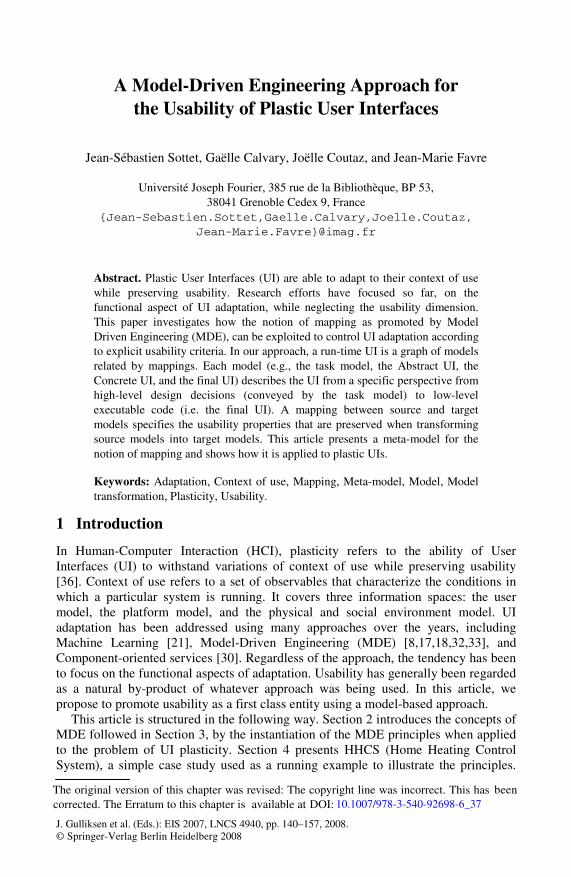
Although promising, the model-based approach to the development of UIs has not met wide acceptance: developers have to learn a new specification language, the connection between the specification and the resulting code is hard to understand and control, and the kinds of UI’s that can be built are constrained by the underlying conventional toolkit [19]. However, this early work has established the foundations for transforming high-level specifications into executable code. In particular, the following steps now serve as references for designing and developing UIs: from the domain-dependent Concepts and Task models, an Abstract UI (AUI) is derived which in turn is transformed into a Concrete UI (CUI), followed by the Final UI (Figure 1) [36].
Concepts-Tasks
Final UI
Concrete UI
Abstract UI
Context of use 1 : Vertical transformation
: Horizontal transformation
: Human Intervention
Context of use 2
Concepts-Tasks
Final UI
Concrete UI
Abstract UI
VAQUITAWebRevEnge
Fig. 1. A model-based framework [7] for UI plasticity
As discussed in [7], transformations can be combined and applied to any of these models to support UI adaptation. For example, VAQUITA [5] and WebRevEnge [23] reverse engineer HTML source files into more abstract descriptions (respectively AUI and task levels), and from there, depending on the tool, either retarget and generate the UI or are combined with retargeting and/or forward engineering tools (Figure 1). This means that developers can produce the models they are familiar with – including source code for fine-tuned elegant UIs, and then use the tools that support the appropriate transformations to retarget the UI to a different context of use. Transformations and models are at the heart of MDE.
The motivation for MDE is the integration of very different know-how and software techniques. Over the years, the field of software engineering has evolved into the development of many paradigms and application domains leading to the emergence of multiple Technological Spaces (TS). "A technological space is a working context with a set of associated concepts, body of knowledge, tools, required skills, and possibilities" [14]. Examples of technological spaces include documentware concerned with digital
142 J.-S. Sottet et al.
documents using XML as the fundamental language to express specific solutions, dataware related to data base systems, ontologyware, etc. In HCI, a java-based control panel running on a PDA can be used to control a web-based application running on a PC. Today, technological spaces can no longer evolve in autarky. Most of them share challenges of increasing complexity, such as adaptation, to which they can only offer partial solutions. Thus, we are in a situation where concepts, approaches, skills, and solutions, need to be combined to address common problems. MDE aims at achieving integration by defining gateways between technological spaces. The hypothesis is that models, meta-models, model transformations, and mappings, offer the appropriate means.
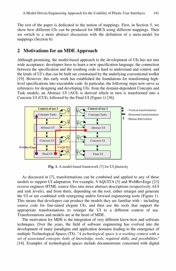
A model is a representation of a thing (e.g., a system), with a specific purpose. It is “able to answer specific questions in place of the actual thing under study” [4]. Thus, a model, built to address one specific aspect of a problem, is by definition a simplification of the actual thing. For example, a task model is a simplified representation of some human activities (the actual thing under study), but it provides answers about how “representative users” proceed to reach specific goals. Things and models are systems. Model is a role of representation that a system plays for another one. Models form oriented graphs (µ graphs) whose edges denote the µ relation “is represented by” (Figure 2). Models may be contemplative (they cannot be processed automatically by computers) or productive (they can be processed by computers). Typically, scenarios developed in HCI [27] are contemplative models of human experience in a specified setting. On the other hand, the task model exploited in TERESA [3] is productive.
In order to be processed (by humans, and/or by computers), a model must comply with some shared syntactic and semantic conventions: it must be a well-formed expression of a language. This is true both for productive and contemplative models: most contemplative models developed in HCI use a mix of drawings and natural language. A TERESA [3] task model is compliant with CTT [25]. A language is the set of all well-formed expressions that comply with a grammar (along with a semantics). In turn, a grammar is a model from which one can produce well-formed expressions (or models). Because a grammar is a model of a set of models (ε relation “is part of” on Figure 2), it is called a meta-model. CTT [25] is a meta-model for expressing specific task models.
A meta-model is a model of a set of models that comply with it. It sets the rules for producing models. It does not represent models. Models and meta-models form a χ tree: a model complies to a single meta-model, whereas a meta-model may have multiple compliant models. In the same way, a meta-meta-model is a model of a set of meta-models that are compliant with it. It does not represent meta-models, but sets the rules for producing distinct meta-models. The OMG Model-Driven Architecture (MDA) initiative has introduced a four-layer modeling stack as a way to express the integration of a large diversity of standards using MOF (Meta Object Facility) as the unique meta-meta-model. This top level is called M3, giving rise to meta-models, models and instances (respectively called M2, M1 and M0 levels). MDA is a specific MDE deployment effort around industrial standards including MOF, UML, CWM, QVT, etc. The µ and χ relations, however, do not tell how models are produced within a technological space, nor how they relate to each other across distinct technological spaces. The notions of transformation and mapping is the MDE answer to these issues.
A Model-Driven Engineering Approach for the Usability of Plastic User Interfaces 143
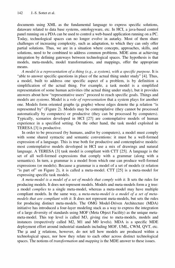
Fig. 2. Basic concepts and relations in MDE
In the context of MDE, a transformation is the production of a set of target models from a set of source models, according to a transformation definition. A transformation definition is a set of transformation rules that together describe how source models are transformed into target models [16]. Source and target models are related by the τ relation “is transformed into”. Note that a set of transformation rules is a model (a transformation model) that complies with a transformation meta-model. τ expresses an overall dependency between source and target models. However, experience shows that finer grain of correspondence needs to be expressed. Typically, the incremental modification of one source element should be propagated easily into the corresponding target element(s) and vice versa. The need for traceability between source and target models is expressed as mappings between source and target elements of these models. For example, each task of a task model and the concepts involved to achieve the task, are rendered as a set of interactors in the CUI model. Rendering is a transformation where tasks and their concepts are mapped into workspaces which, in turn, are mapped into windows populated with widgets in case of graphical UIs. The correspondence between the source task (and concepts) and its target workspace, window and widgets, is maintained as mappings. Mappings will be illustrated in Section 5 for the purpose of UI plasticity and meta-modeled in Section 6.
Transformations can be characterized within a four-dimension space: The transformation may be automated (it can be performed by a computer autonomously), it may be semi-automated (requiring some human intervention), or it may be manually performed by a human. A transformation is vertical when the source and target models reside at different levels of abstraction (Figure 1). Traditional UI generation is a vertical top down transformation from high-level descriptions (such as a task model) to code generation. Reverse engineering is also a vertical transformation, but it proceeds bottom up, typically from executable code to some high-level representation by the way of abstraction. A transformation is horizontal when the source and target models reside at the same level of abstraction (Figure 1). For example, translating a Java source code into C code preserves the original level of abstraction. Transformations are endogenous when the source and target models are expressed in the same language (i.e., are compliant to the same meta-model). Transformations are exogenous when sources and targets are expressed in different languages while belonging to the same technological space. When crossing technological spaces (e.g., transforming a Java source code into a
144 J.-S. Sottet et al.
JavaML document), then additional tools (called exporters and importers) are needed to bridge the gap between the spaces. Inter-technological transformations are key to knowledge and technical integration.
As discussed next, our approach to the problem of plastic UI is to fully exploit the MDE theoretic framework opening the way to the explicit expression of usability to drive the adaptation process.
3 MDE for UI Plasticity
Early work in the automatic generation of UIs [32] as well as more recent work in UI adaptation adhere only partially to the MDE principles. Our approach differs from previous work [8,17,18,32] according to the following four principles.
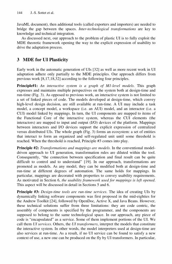
Principle#1: An interactive system is a graph of M1-level models. This graph expresses and maintains multiple perspectives on the system both at design-time and run-time (Fig. 3). As opposed to previous work, an interactive system is not limited to a set of linked pieces of code. The models developed at design-time, which convey high-level design decision, are still available at run-time. A UI may include a task model, a concept model, a workspace (i.e. an AUI) model, and an interactor (i.e. a CUI) model linked by mappings. In turn, the UI components are mapped to items of the Functional Core of the interactive system, whereas the CUI elements (the interactors) are mapped to input and output (I/O) devices of the platform. Mappings between interactors and I/O devices support the explicit expression of centralized versus distributed UIs. The whole graph (Fig. 3) forms an ecosystem: a set of entities that interact to form an organized and self-regulated unit until some threshold is reached. When the threshold is reached, Principle #3 comes into play.
Principle #2: Transformations and mappings are models. In the conventional model-driven approach to UI generation, transformation rules are diluted within the tool. Consequently, “the connection between specification and final result can be quite difficult to control and to understand” [19]. In our approach, transformations are promoted as models. As any model, they can be modified both at design-time and run-time at different degrees of automation. The same holds for mappings. In particular, mappings are decorated with properties to convey usability requirements. As motivated in Section 6, the usability framework used for mappings is left opened. This aspect will be discussed in detail in Sections 5 and 6.
Principle #3: Design-time tools are run-time services. The idea of creating UIs by dynamically linking software components was first proposed in the mid-eighties for the Andrew Toolkit [24], followed by OpenDoc, Active X, and Java Beans. However, these technical solutions suffer from three limitations: they are code centric, the assembly of components is specified by the programmer, and the components are supposed to belong to the same technological space. In our approach, any piece of code is “encapsulated” as a service. Some of them implement portions of the UI. We call them UI services. Others, the UI transformers, interpret the models that constitute the interactive system. In other words, the model interpreters used at design-time are also services at run-time. As a result, if no UI service can be found to satisfy a new context of use, a new one can be produced on the fly by UI transformers. In particular,
A Model-Driven Engineering Approach for the Usability of Plastic User Interfaces 145
Functional core User Interface
Context of use
Fig. 3. A UI is a graph of models. Mappings define both the rationale of each UI element and the UI deployment on the functional core and the context of use.
the availability of a task model at run-time makes it possible to perform deep UI adaptation based on high-level abstractions.
Principle #4: Humans are kept in the loop. HCI design methods produce a large body of contemplative models such as scenarios, drawings, storyboards, and mock-ups. These models are useful reference material during the design process. On the other hand, because they are contemplative, they can only be transformed manually into productive models. Manual transformation supports creative inspiration, but is prone to wrong interpretation and to loss of key information. On the other hand, experience shows that automatic generation is limited to very conventional UIs. To address this problem, we accept to support a mix of automated, semi-automated, and manually performed transformations. For example, given our current level of knowledge, the transformation of a “value-centered model” [9] into a “usability model” such as that of [2], can only be performed manually by designers. Semi-automation allows designers (or end-users) to adjust the target models that result from transformations. For example, a designer may decide to map a subset of an AUI with UI services developed with the latest post-WIMP toolkit. The only constraint is that the hand-coded executable piece is modeled according to an explicit meta-model and is encapsulated as a service. This service can then be dynamically retrieved and linked to the models of the interactive system by the way of mappings. With productive models at multiple levels of abstraction, the system can reason at run-time about its own design. In a nutshell, the components of a particular system at run-time can be a mix of generated and hand-coded highly tuned pieces of UI. By the way of a meta-UI [11], end-users can dynamically inform the adaptation process of their preferences.
To summarize, our approach to the problem of UI plasticity brings together MDE (Model Driven Engineering) and SOA (Service Oriented Approach) within a unified framework that covers both the development stage and the run-time phase of interactive systems. In this paper, we investigate how usability can be described and controlled by the way of mappings given that an interactive system is a graph of
146 J.-S. Sottet et al.
models. We use HHCS as an illustrative example before going into a more formal definition of the notion of mapping and its relation with that of transformation.
4 The Home Heating Control System: Overall Description
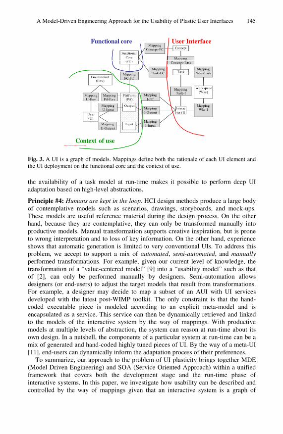
Our Home Heating Control System (HHCS) makes it possible for users to control the temperature of their home using different devices. Examples include a dedicated wall-mounted display, a Web browser running on a PDA, or a Java-enabled watch. As shown in Fig. 4, many UI variants are made possible, depending on the device screen size, as well as on the set of usability properties that HCI designers have elicited as key:
• From a functional perspective, the four UI’s of Fig. 4 are equivalent: they support the same set of tasks, with the same set of rooms (the living room, the cellar and the kitchen) whose temperature may be set between 15°C and 18°C;
• From a non-functional perspective, these UI’s do not satisfy the same set of usability properties. In particular, according to C. Bastien and D. Scapin’s usability framework [2], prompting (a factor for guidance), prevention against errors (a factor for error management), and minimal actions (a factor for workload) are not equally supported by the four UI solutions. In Fig. 4-a), the unit of measure (i.e. Celsius versus Fahrenheit) is not displayed. The same holds for the room temperature whose range of values is not made observable. As a result, prompting is not fully supported. In Fig. 4-b), the lack of prompting is repaired but the user is still not prevented from entering wrong values. Solutions in Fig. 4-c) and Fig. 4-d) satisfy the prompting criteria as well as prevention against error. Moreover, Fig. 4-d) improves the minimal actions recommendation (a factor for workload) by eliminating the “Select room” navigation (also called articulatory) task. The UIs of Fig. 4-a to 4-c satisfy homogeneity-consistency because the same type of interactor (i.e. a web link) is used to choose a room.
(a) temperature values are not observable
(b) The unit of measure and the validThe unit of measure and the validtemperature values are both observable
(c) The user is prevented from making errors (d) The user is prevented from navigation tasks
Fig. 4. Four functionally-equivalent UIs that differ from the set of usability criteria used to produce them
A Model-Driven Engineering Approach for the Usability of Plastic User Interfaces 147
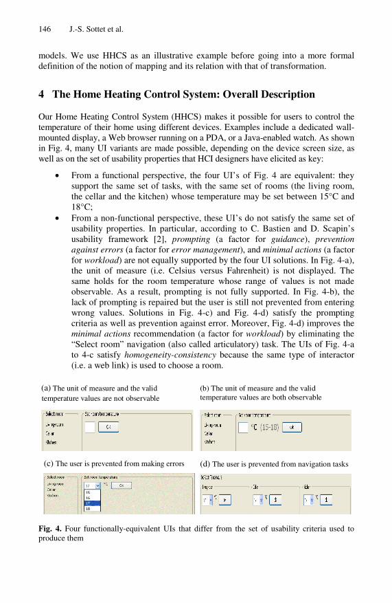
Fig. 5. A subset of the graph of M1-models for HHCS. Each model is compliant to a meta-model (M2-level). Each M1-level model of this figure is related to another M1-level model by the way of some mapping to form a sub-graph of Fig.1.
The purpose of this paper is not to define new meta-models but to show how mappings are appropriate for conveying usability properties. Whatever the UI is (Fig.4-a, b, c or d), HHCS is a graph of models, each of them depicting a specific perspective. Each model (M1-level) is compliant to a meta-model (M2-level). Fig. 5
148 J.-S. Sottet et al.
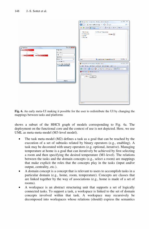
Fig. 6. An early meta-UI making it possible for the user to redistribute the UI by changing the mappings between tasks and platforms
shows a subset of the HHCS graph of models corresponding to Fig. 4a. The deployment on the functional core and the context of use is not depicted. Here, we use UML as meta-meta-model (M3-level model).
• The task meta-model (M2) defines a task as a goal that can be reached by the execution of a set of subtasks related by binary operators (e.g., enabling). A task may be decorated with unary operators (e.g. optional, iterative). Managing temperature at home is a goal that can iteratively be achieved by first selecting a room and then specifying the desired temperature (M1-level). The relations between the tasks and the domain concepts (e.g., select a room) are mappings that make explicit the roles that the concepts play in the tasks (input and/or output, centrality, etc.).
• A domain concept is a concept that is relevant to users to accomplish tasks in a particular domain (e.g., home, room, temperature). Concepts are classes that are linked together by the way of associations (e.g., home is made of a set of rooms).
• A workspace is an abstract structuring unit that supports a set of logically connected tasks. To support a task, a workspace is linked to the set of domain concepts involved within that task. A workspace may recursively be decomposed into workspaces whose relations (should) express the semantics
A Model-Driven Engineering Approach for the Usability of Plastic User Interfaces 149
of tasks operators (e.g., gives access to for the enabling operator). In Fig. 4a-b-c, there are three workspaces: one per task.
• An interactor is the basic construct for CUIs (e.g., window, panel, group box, link, text field, button). It is a computational abstraction that allows the rendering and manipulation of entities that require interaction resources (e.g., input/output devices). Each interactor is aware of the task and domain concepts it represents, and the workspace in which it takes place.
Fig. 6 shows a basic meta-UI that allows the user (either the designer and/or the end-user) to observe and manipulate a sub-graph of the M1-level models of HHCS. In this early prototype, the meta-UI is limited to the task and platform models. By selecting a task of the task model, then selecting the platform(s) onto which the user would like to execute the task, the user can dynamically redefine the redistribution of the UI over the resources currently available. The UI is re-computed and redistributed on the fly, thus ensuring UI consistency. On Fig. 6, two platforms are available (a PC HTML and a PC XUL-enabled). End-users can map the tasks “Select room” and “Set room temperature” respectively, to the PDA-HTML platform and to the PC-XUL platform, resulting in the Final UI shown in Fig.6.
This toy meta-UI shows only the mappings. The properties that these mappings convey are neither observable nor controllable. This is the next implementation step for fully demonstrating the conceptual advances that we present next. Section 5 is about the mappings used in HHCS whereas Section 6 goes one step further with the definition of a meta-model for mappings.
5 Mappings in HHCS
In HHCS, we have used Bastien-Scapin’s recommendations as our usability framework1. Due to lack of space, we limit our analysis to four of the eight criteria of this framework:
• Task compatibility; • Guidance in terms of Prompting and Grouping/Distinction of items; • Error Management in terms of Error prevention; • Workload in terms of Minimal actions.
In model-driven UI generation, usability criteria motivate the way abstract models are vertically transformed into more concrete models. Typically, Grouping/Distinction of items motivates the decomposition of UIs in terms of workspaces so that the concepts manipulated within a task are grouped together. By doing so, the distinction between the tasks that users can accomplish, is made salient. In our approach, we use usability criteria not only to motivate a particular design, but also to support plasticity at run-time. A mapping between elements of source and target models, is specified either manually in a semi-formal way by the designer, or is created automatically by the system as the result of a transformation function. The choice of the appropriate transformation function is performed, either by the system, or specified by users (the 1 As discussed in Section 6, other frameworks are valid as well.
150 J.-S. Sottet et al.
(a)
(b)
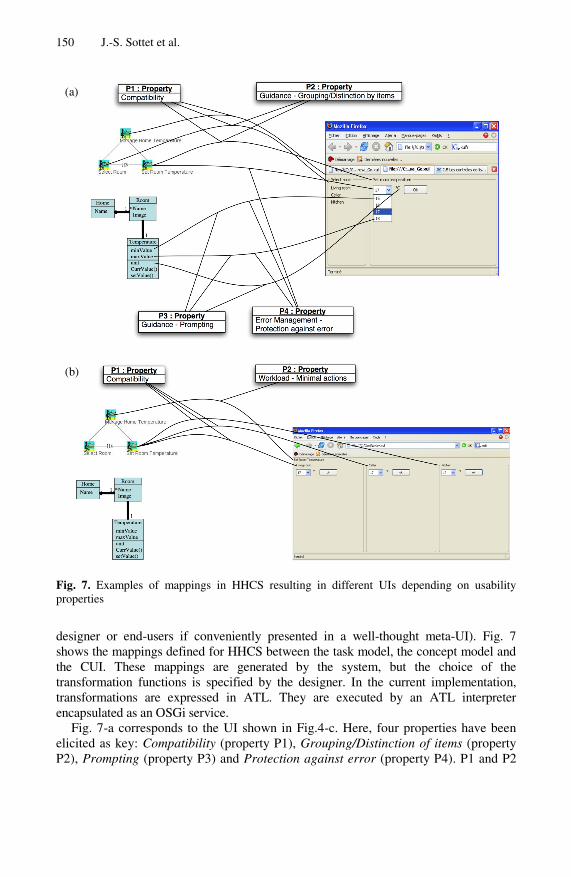
Fig. 7. Examples of mappings in HHCS resulting in different UIs depending on usability properties
designer or end-users if conveniently presented in a well-thought meta-UI). Fig. 7 shows the mappings defined for HHCS between the task model, the concept model and the CUI. These mappings are generated by the system, but the choice of the transformation functions is specified by the designer. In the current implementation, transformations are expressed in ATL. They are executed by an ATL interpreter encapsulated as an OSGi service.
Fig. 7-a corresponds to the UI shown in Fig.4-c. Here, four properties have been elicited as key: Compatibility (property P1), Grouping/Distinction of items (property P2), Prompting (property P3) and Protection against error (property P4). P1 and P2
A Model-Driven Engineering Approach for the Usability of Plastic User Interfaces 151
are attached to the mappings that result from the transformation function between tasks and workspaces. As shown in Fig. 7-a, this transformation function has generated one workspace per task (a workspace for selecting a room, and a workspace to set room temperature). These workspaces are spatially close to each other (they correspond to tasks that share the same parent task), and each workspace makes observable the concepts manipulated by the corresponding task. As a result, the CUI fully supports user’s tasks and is well-structured. Property P3 (Prompting) and Property P4 (Protection against errors) influences the way concepts and tasks are represented in terms of interactors. Because of Property P3, the unit of measure as well as the min and max values for a room temperature are made observable. Because of Property P4, the possible values for a room temperature are rendered as a pull-down menu.
Fig. 7-b) shows a very different CUI for the same set of tasks and concepts, but using a different set of properties. In particular, the Minimal actions Property aims at eliminating navigation tasks. As a result, because the screen real estate is sufficient, there is one workspace per room, and the task “Select a room” is performed implicitly by setting the temperature directly in the appropriate workspace.
Next section presents our meta-model for mappings. This meta-model is general, applicable to HCI for reasoning on usability-driven transformations.
6 Formal Definition of Mapping
In mathematics, a mapping is “a rule of correspondence established between two sets that associates each member of the first set with a single member of the second” [The American Heritage Dictionary of the English Language, 1970, p. 797]. In MDE, the term “mapping” is related to the notion of “transformation function”, but the overall picture is far from being clear. First, we clarify the notion of transformation as exploited in MDE. Then, we use this notion to propose a meta-model for mappings.
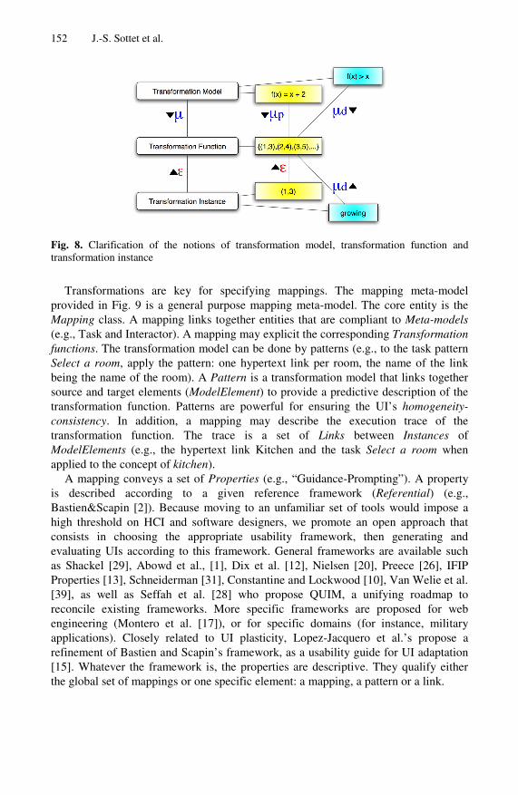
Fig. 8 introduces three terms: transformation model, transformation function and transformation instance. They are illustrated on the mathematical domain. “f(x)=x+2” is a transformation model that is compliant to a mathematical meta-model. A transformation model describes (µ relation) a transformation function in a predictive way: here the set {(1,3),(2,4),(3,5)…} for the function “f” when applied to integers. A transformation function is the set of all the transformation instances inside the domain variation (here, the integers). Transformation instances are subsets (ε relation) of the transformation function. They are the execution trace of the function (here, “f”).
In Fig. 8, the µ relation is refined into µp and µd. These relations respectively stand for predictive and descriptive representations. Predictive means that there is no ambiguity: the transformation model (e.g., “f(x)=x+2”) fully specifies the transformation function. Descriptive refers to a qualifier (e.g., “growing”). It does not specify the transformation function, but provides additional information. In Fig. 8, two examples are provided: “growing” and “f(x)>x”. They respectively deal with transformation instances and model. In the first case, the description is made a posteriori whilst it is made a priori in the second one. A posteriori descriptions are subject to incompleteness and/or errors due to too few samples.
152 J.-S. Sottet et al.
Fig. 8. Clarification of the notions of transformation model, transformation function and transformation instance
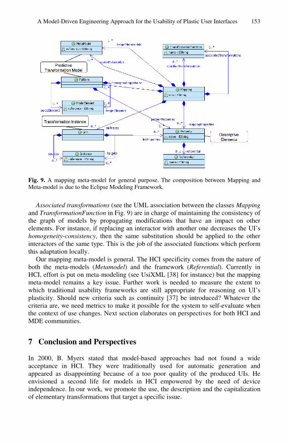
Transformations are key for specifying mappings. The mapping meta-model provided in Fig. 9 is a general purpose mapping meta-model. The core entity is the Mapping class. A mapping links together entities that are compliant to Meta-models (e.g., Task and Interactor). A mapping may explicit the corresponding Transformation functions. The transformation model can be done by patterns (e.g., to the task pattern Select a room, apply the pattern: one hypertext link per room, the name of the link being the name of the room). A Pattern is a transformation model that links together source and target elements (ModelElement) to provide a predictive description of the transformation function. Patterns are powerful for ensuring the UI’s homogeneity-consistency. In addition, a mapping may describe the execution trace of the transformation function. The trace is a set of Links between Instances of ModelElements (e.g., the hypertext link Kitchen and the task Select a room when applied to the concept of kitchen).
A mapping conveys a set of Properties (e.g., “Guidance-Prompting”). A property is described according to a given reference framework (Referential) (e.g., Bastien&Scapin [2]). Because moving to an unfamiliar set of tools would impose a high threshold on HCI and software designers, we promote an open approach that consists in choosing the appropriate usability framework, then generating and evaluating UIs according to this framework. General frameworks are available such as Shackel [29], Abowd et al., [1], Dix et al. [12], Nielsen [20], Preece [26], IFIP Properties [13], Schneiderman [31], Constantine and Lockwood [10], Van Welie et al. [39], as well as Seffah et al. [28] who propose QUIM, a unifying roadmap to reconcile existing frameworks. More specific frameworks are proposed for web engineering (Montero et al. [17]), or for specific domains (for instance, military applications). Closely related to UI plasticity, Lopez-Jacquero et al.’s propose a refinement of Bastien and Scapin’s framework, as a usability guide for UI adaptation [15]. Whatever the framework is, the properties are descriptive. They qualify either the global set of mappings or one specific element: a mapping, a pattern or a link.
A Model-Driven Engineering Approach for the Usability of Plastic User Interfaces 153
Fig. 9. A mapping meta-model for general purpose. The composition between Mapping and Meta-model is due to the Eclipse Modeling Framework.
Associated transformations (see the UML association between the classes Mapping and TransformationFunction in Fig. 9) are in charge of maintaining the consistency of the graph of models by propagating modifications that have an impact on other elements. For instance, if replacing an interactor with another one decreases the UI’s homogeneity-consistency, then the same substitution should be applied to the other interactors of the same type. This is the job of the associated functions which perform this adaptation locally.
Our mapping meta-model is general. The HCI specificity comes from the nature of both the meta-models (Metamodel) and the framework (Referential). Currently in HCI, effort is put on meta-modeling (see UsiXML [38] for instance) but the mapping meta-model remains a key issue. Further work is needed to measure the extent to which traditional usability frameworks are still appropriate for reasoning on UI’s plasticity. Should new criteria such as continuity [37] be introduced? Whatever the criteria are, we need metrics to make it possible for the system to self-evaluate when the context of use changes. Next section elaborates on perspectives for both HCI and MDE communities.
7 Conclusion and Perspectives
In 2000, B. Myers stated that model-based approaches had not found a wide acceptance in HCI. They were traditionally used for automatic generation and appeared as disappointing because of a too poor quality of the produced UIs. He envisioned a second life for models in HCI empowered by the need of device independence. In our work, we promote the use, the description and the capitalization of elementary transformations that target a specific issue.
154 J.-S. Sottet et al.
A UI is described as a graph of models and mappings both at design time and run-time. At design time, mappings convey properties that help the designer in selecting the most appropriate transformation functions. Either the target element of the mapping is generated according to the transformation function that has been selected, or the link is made by the designer who then describes the mapping using a transformation model. We envision adviser tools for making the designer aware of the properties he/she is satisfying or neglecting.
At run-time, mappings are key for reasoning on usability. However, it is not easy as (1) there is not a unique consensual reference framework; (2) ergonomic criteria may be inconsistent and, as a result, require difficult tradeoffs. Thus, (1) the meta-model will have to be refined according to these frameworks; (2) a meta-UI (i.e., the UI of the adaptation process) may be relevant for negotiating tradeoffs with the end-user.
Beyond HCI, this work provides a general contribution to MDE. It defines a mapping meta-model and clarifies the notions of mapping and transformation. Mappings are more than a simple traceability link. They can be either predictive (transformation specifications) or descriptive (the properties that are conveyed), as a result covering both the automatic generation and the hand-made linking. Moreover mapping models can embed transformation in order to manage models consistency. This is new in MDE as most of the approaches currently focus on direct transformation. Our mapping meta-model will be stored in the international Zoo of meta-models: the ZOOOMM project [40]. Acknowledgments. This work has been supported by the network of excellence SIMILAR and the ITEA EMODE project. The authors warmly thank Xavier Alvaro for the implementation of the prototype.
References
1. Abowd, G.D., Coutaz, J., Nigay, L.: Structuring the Space of Interactive System Properties. In: Larson, J., Unger, C. (eds.) Engineering for Human-Computer Interaction, pp. 113–126. Elsevier, Science Publishers B.V. (North-Holland), IFIP (1992)
2. Bastien, J.M.C., Scapin, D.: Ergonomic Criteria for the Evaluation of Human-Computer, Technical report INRIA, N°156 (June 1993)
3. Berti, S., Correani, F., Mori, G., Paterno, F., Santoro, C.: TERESA: a transformation-based environment for designing and developing multi-device interfaces. In: Conference on Human Factors in computing Systems, CHI 2004 extended abstracts on Human factors in computing systems, Vienna, Austria, pp. 793–794 (2004)
4. Bézivin, J.: In Search of a Basic Principle for Model Driven Engineering, CEPIS, UPGRADE. The European Journal for the Informatics Professional (2), 21–24 (2004)
5. Bouillon, L., Vanderdonckt, J.: Retargeting of Web Pages to Other Computing Platforms with VAQUITA. In: Proceedings of the Ninth Working Conference on Reverse Engineering (WCRE 2002), p. 339 (2002)
6. Calvary, G., Coutaz, J., Daassi, O., Balme, L., Demeure, A.: Towards a new generation of widgets for supporting software plasticity: the ’comet’. In: Bastide, R., Palanque, P., Roth, J. (eds.) DSV-IS 2004 and EHCI 2004. LNCS, vol. 3425, pp. 306–324. Springer, Heidelberg (2005)
A Model-Driven Engineering Approach for the Usability of Plastic User Interfaces 155
7. Calvary, G., Coutaz, J., Thevenin, D., Limbourg, Q., Bouillon, L., Vanderdonckt, J.: A unifying reference framework for multi-target user interfaces. Interacting With Computers 15/3, 289–308 (2003)
8. Clerckx, T., Luyten, K., Coninx, K.: Generating Context-Sensitive. In: Sasse, A., Johnson, C. (eds.) Multiple Device Interact 1999, Edinburgh, pp. 110–117. IOS Press Publ., Amsterdam (1999)
9. Cockton, G.: A development Framework for Value-Centred Design. In: ACM Proc. CHI 2005, Late Breaking Results, pp. 1292–1295 (2005)
10. Constantine, L.L., Lockwood, L.A.D.: Software for Use: A Practical Guide to the Models and Methods of Usage-Centred Design. Addison-Wesley, New-York (1999)
11. Coutaz, J.: Meta-User Interfaces for Ambient Spaces. In: Coninx, K., Luyten, K., Schneider, K.A. (eds.) TAMODIA 2006. LNCS, vol. 4385, pp. 1–15. Springer, Heidelberg (2007)
12. Dix, A., Finlay, J., Abowd, G., Beale, R.: Human-Computer Interaction. Prentice-Hall, New-Jersey (1993)
13. IFIP Design Principles for Interactive Software, IFIP WG 2.7 (13.4), Gram, C., Cockton, G.(eds.). Chapman&Hall Publ. (1996)
14. Kurtev, I., Bézivin, J., Aksit, M.: Technological Spaces: An Initial Appraisal. In: Meersman, R., Tari, Z., et al. (eds.) CoopIS 2002, DOA 2002, and ODBASE 2002. LNCS, vol. 2519. Springer, Heidelberg (2002)
15. Lopez-Jaquero, V., Montero, F., Molina, J.P., Gonzalez, P.: A Seamless Development Process of Adaptive User Interfaces Explicitly Based on Usability Properties. In: Bastide, R., Palanque, P., Roth, J. (eds.) DSV-IS 2004 and EHCI 2004. LNCS, vol. 3425, pp. 289–291. Springer, Heidelberg (2005)
16. Mens, T., Czarnecki, K., Van Gorp, P.: A Taxonomy of Model Transformations Language Engineering for Model-Driven Software Development, Dagstuhl (February-March 2004)
17. Montero, F., Vanderdonckt, J., Lozano, M.: Quality Models for Automated Evaluation of Web Sites Usability and Accessibility. In: Koch, N., Fraternali, P., Wirsing, M. (eds.) ICWE 2004. LNCS, vol. 3140. Springer, Heidelberg (2004)
18. Mori, G., Paternò, F., Santoro, C.: CTTE: Support for Developing and Analyzing Task Models for Interactive System Design. IEEE Transactions on Software Engineering, 797–813 (August 2002)
19. Myers, B., Hudson, S.E., Pausch, R.: Past, Present, and Future of User Interface Software Tools. Transactions on Computer-Human Interaction (TOCHI) 7(1) (2000)
20. Nielsen, J.: Heuristic evaluation. In: Nielsen, J., Mack, R.L. (eds.) Usability Inspection Methods. John Wiley & Sons, New York (1994)
21. Njike, H., Artières, T., Gallinari, P., Blanchard, J., Letellier, G.: Automatic learning of domain model for personalized hypermedia applications. In: International Joint Conference on Artificial Intelligence, IJCA, Edinburg, Scotland, p. 1624 (2005)
22. Nobrega, L., Nunes, J.N., Coelho, H.: Mapping ConcurTaskTrees into UML 2.0. In: Gilroy, S.W., Harrison, M.D. (eds.) DSV-IS 2005. LNCS, vol. 3941, pp. 237–248. Springer, Heidelberg (2006)
23. Paganelli, L., Paternò, F.: Automatic Reconstruction of the Underlying Interaction Design of Web Applications. In: Proceedings Fourteenth International Conference on Software Engineering and Knowledge Engineering, July 2002, pp. 439–445. ACM Press, Ischia (2002)
24. Palay, A., Hansen, W., Kazar, M., Sherman, M., Wadlow, M., Neuendorffer, T., Stern, Z., Bader, M., Peters, T.: The Andrew Toolkit: An Overview. In: Proc. On Winter 1988 USENIX Technical Conf., pp. 9–21. USENIX Ass., Berkeley, CA, (1988)
156 J.-S. Sottet et al.
25. Paterno’, F., Mancini, C., Meniconi, S.: ConcurTaskTrees: A Diagrammatic Notation for Specifying Task Models. In: Proceedings Interact 1997, Sydney, pp. 362–369. Chapman&Hall, Boca Raton (1997)
26. Preece, J., Rogers, Y., Sharp, H., Benyon, D., Holland, S., Carey, T.: Human-Computer Interaction. Addison Wesley Publ., Wokingham (1994)
27. Rosson, M.B., Carroll, J.M.: Usability Engineering: Scenario-Based Development of Human-Computer Interaction. Morgan Kaufman, San Francisco (2002)
28. Seffah, A., Donyaee, M., Kline, R.B.: Usability and quality in use measurement and metrics: An integrative model. Software Quality Journal (2004)
29. Shackel, B.: Usability-Context, Framework, Design and Evaluation. In: Human Factors for Informatics Usability, pp. 21–38. Cambridge University Press, Cambridge (1991)
30. Sheshagiri, M., Sadeh, N., Gandon, F.: Using Semantic Web Services for Context-Aware Mobile Applications. In: Proceedings of ACM MobiSys. 2004 Workshop on Context Awareness, Boston, Massachusetts, USA (June 2004)
31. Schneiderman, B.: Designing User Interface Strategies for effective Human-Computer Interaction, 3rd edn., 600 pages. Addison-Wesley Publ., Reading (1997)
32. da Silva, P.: User Interface Declarative Models and Development Environments: A Survey. In: Palanque, P., Paternó, F. (eds.) DSV-IS 2000. LNCS, vol. 1946, pp. 207–226. Springer, Heidelberg (2001)
33. Sottet, J.S., Calvary, G., Favre, J.M., Coutaz, J., Demeure, A., Balme, L.: Towards Model-Driven Engineering of Plastic User Interfaces. In: Bruel, J.-M. (ed.) MoDELS 2005. LNCS, vol. 3844, pp. 191–200. Springer, Heidelberg (2006)
34. Sottet, J.S., Calvary, G., Favre, J.M.: Towards Mappings and Models Transformations for Consistency of Plastic User Interfaces. In: The Many Faces of Consistency, Workshop CHI 2006, Montréal, Québec, Canada, April 22-23 (2006)
35. Sottet, J.S., Calvary, G., Favre, J.M.: Mapping Model: A First Step to Ensure Usability for sustaining User Interface Plasticity. In: Proceedings of the MoDELS 2006 Workshop on Model Driven Development of Advanced User Interfaces, October 3 (2006)
36. Thevenin, D.: Plasticity of User Interfaces: Framework and Research Agenda. In: Sasse, A., Johnson, C. (eds.) Proc. Interact 1999, Edinburgh, pp. 110–117. IFIP IOS Press Publ., Amsterdam (1999)
37. Trevisan, D., Vanderdonckt, J., Macq, B.: Continuity as a usability property. In: HCI 2003 - 10th Intl Conference on Human-Computer Interaction, Heraklion, Greece, June 22-27, 2003, vol. I, pp. 1268–1272 (2003)
38. UsiXML, http://www.usixml.org/ 39. Van Welie, M., van der Veer, G.C., Eliëns, A.: Usability Properties in Dialog Models. In:
6th International Eurographics Workshop on Design Specification and Verification of Interactive Systems DSV-IS 1999, Braga, Portugal, 2-4 June 1999, pp. 238–253 (1999)
40. Zooomm Project, http://www.zooomm.org
Questions
Yves Vandriessche: Question: How are you handling the layouts, should there be a model?
Answer: The layout model is in the transformation but we should really do that in another model.
A Model-Driven Engineering Approach for the Usability of Plastic User Interfaces 157
Question: There is no problem adding more models?
Answer: No problems, this is what the Zoom project is about.
Nick Graham: Question: Tell me about your platform model?
Answer: It is very simple, work by Dennis Wagelaar is interesting and I would like a more complex model.
Jan Gulliksen: Question: What about the end-user as designer, how difficult is it?
Answer: I am interested in end-user programming. I would like to achieve that and this is what we would like to do in the future.
Phil Gray: Question: Single task single user, what about multiple user multiple task?
Answer: Yes we have multiple users. How the task is described – we are talking about a Petri net model as a means of describing this. For some users some models are better than others, an evolution model is something we are working on in the team.
Jo Vermeulen: Comment: An interesting paper around a meta user interface editors is "User Interface Façades" which was presented at UIST last year. End-users are able to create new dialogs combining a couple of widgets from an existing dialog, or transform widgets (e.g. switch from a group of radio buttons to a combo box). This might be useful for your work if you want to look at extending it to enable user interface adaptation by end-user. The exact details of the paper: W. Stuerzlinger, O. Chapuis, D. Phillips and N. Roussel. User Interface Façades: Towards Fully Adaptable User Interfaces. In Proceedings of UIST'06, the 19th ACM Symposium on User Interface Software and Technology, pages 309-318, October 2006. ACM Press. URL: http://insitu.lri.fr/metisse/facades/ PDF: http://insitu.lri.fr/~ roussel/publications/UIST06-facades.pdf