a method for quantitative measurement by thermal neutron radiography
TRANSCRIPT
This article was downloaded by: [DUT Library]On: 05 October 2014, At: 23:41Publisher: Taylor & FrancisInforma Ltd Registered in England and Wales RegisteredNumber: 1072954 Registered office: Mortimer House, 37-41Mortimer Street, London W1T 3JH, UK
Nondestructive Testingand EvaluationPublication details, includinginstructions for authors andsubscription information:http://www.tandfonline.com/loi/gnte20
A METHOD FORQUANTITATIVEMEASUREMENT BYTHERMAL NEUTRONRADIOGRAPHYN. TAKENAKA a , H. ASANO a , T. FUJII a
& M. MATSUBAYASHI ba Department of MechanicalEngineering. Kobe University,Rokkodai, Nada, Kobe 657-8501, Japanb Tokai Establishment Japan AtomicEnergy Research Institute , Tokai,Naka, Ibaraki 319-1195, JapanPublished online: 27 Apr 2007.
To cite this article: N. TAKENAKA , H. ASANO , T. FUJII & M.MATSUBAYASHI (2001) A METHOD FOR QUANTITATIVE MEASUREMENTBY THERMAL NEUTRON RADIOGRAPHY, Nondestructive Testing andEvaluation, 16:2-6, 345-354, DOI: 10.1080/10589750108953089
To link to this article: http://dx.doi.org/10.1080/10589750108953089
PLEASE SCROLL DOWN FOR ARTICLE

Taylor & Francis makes every effort to ensure the accuracy ofall the information (the “Content”) contained in the publicationson our platform. However, Taylor & Francis, our agents, and ourlicensors make no representations or warranties whatsoever asto the accuracy, completeness, or suitability for any purposeof the Content. Any opinions and views expressed in thispublication are the opinions and views of the authors, andare not the views of or endorsed by Taylor & Francis. Theaccuracy of the Content should not be relied upon and shouldbe independently verified with primary sources of information.Taylor and Francis shall not be liable for any losses, actions,claims, proceedings, demands, costs, expenses, damages, andother liabilities whatsoever or howsoever caused arising directlyor indirectly in connection with, in relation to or arising out ofthe use of the Content.
This article may be used for research, teaching, and privatestudy purposes. Any substantial or systematic reproduction,redistribution, reselling, loan, sub-licensing, systematic supply,or distribution in any form to anyone is expressly forbidden.Terms & Conditions of access and use can be found at http://www.tandfonline.com/page/terms-and-conditions
Dow
nloa
ded
by [
DU
T L
ibra
ry]
at 2
3:41
05
Oct
ober
201
4
Nondestr, Test. Eval., Vol. 16. pp. 345-354Reprints availabledirectlyfrom the publisherPhotocopyingpennitted by licenseonly
© 2001 OPA (Overseas Publishers Association) N.V.Published by licenseunder
the Gordon and Breach SciencePublishers imprint.
Printed in Malaysia.
A METHOD FOR QUANTITATIVEMEASUREMENT BY THERMAL
NEUTRON RADIOGRAPHY
N. TAKENAKAa•• , H. ASANOa
, T. FUJIIa
and M. MATSUBAYASHIb
"Department of Mechanical Engineering. Kobe University,Rokkodai, Nada, Kobe 657-8501 Japan; "Tokai Establishment.
Japan Atomic Energy Research Institute, Tokai, Naka,Ibaraki 319-1195 Japan
(Received 14 July 2000)
A quantitative measurement method by thermal neutron radiography was proposed fortwo-dimensional void fraction measurement in two-phase flow. The umbra method wasmodified for two-dimensional measurement by using a neutron absorber grid. Imageprocessing methods to compensate for the effects of neutrons scattered in the object andoptical rays scattered in camera were developed. A step made from acrylic resin wastested with a B.C grid 3 mm in width and 3 mm in interval. It was shown that twodimensional quantitative measurement was possible with this method in sacrifice of thespatial resolution.
Keywords: Neutron radiography; Quantitative measurement; Umbra method; Scattering
1. INTRODUCTION
Visualization by neutron radiography is suitable for two-phase flowstudies. Measurement of the void fraction which is the volumetric ratioof the gas phase to the two-phase mixture is important to analyze thetwo-phase flow phenomena. However, it is not easy to measure thevoid fraction quantitatively from the images obtained by neutron
·Corresponding author. Tel.: +81-78-803-6118, Fax: +81-78-803-6122, e-mail:[email protected]
345
Dow
nloa
ded
by [
DU
T L
ibra
ry]
at 2
3:41
05
Oct
ober
201
4
346 N. TAKENAKA et at.
radiography. The brightness of the image is not always proportional tothe value calculated by linear attenuation equations. Some methodshave already been proposed for the quantitative measurement.
Glickstein et at. [I] used Monte-Carlo simulation for quantitativemeasurement and applied it to void fraction measurement byestimating the neutron scattering as an inverse problem of neutroninteraction. No special experimental preparation is required with thismethod. The profile of the void fraction distribution should beassumed to obtain an unique answer to solve the inverse problem.
Hrdlicka and Peterka [2], Hibiki el at. [3] and Yoshii and Kobayashi[4] proposed to increase the distance between the converter and theobject to reduce the possibility of the scattered neutrons falling on theimage in the converter. This method is easy but the spatial resolution isreduced if the L/D of the system is not high.
Tamaki [5] inserted a collimator made of neutron absorber betweenthe converter and the object to reduce the neutrons the direction ofwhich was changed after scattering in the object. A honeycombpainted with Gadolium was tested. By changing the LfD of thehoneycomb the reduction rate of the scattered neutrons could beestimated. When the L/D of the system was low, the visible field wasquite reduced due to the shadow of the collimator on the converter.
Kobayashi et at. [6] employed the umbra method to compensatethe neutron scattering effects. A cadmium tape was placed betweenthe object and the source to make the umbra of the tape on theconverter. The brightness due to the scattered neutron could bemeasured by the brightness at the umbra. Compensation was made bysubtracting the image with the tape from that without it. This methodis expected to compensate the effects of the scattered scintillationoptical rays. One-dimensional quantitative distribution is obtainablewith this method.
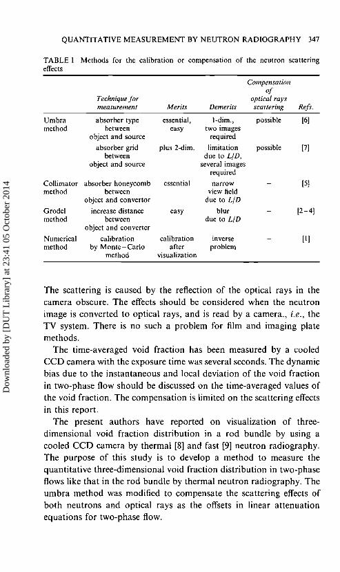
Murata et at. [7] modified this method to two-dimensionalmeasurement by using a grid made of several tapes. The interval ofthe tapes should be long enough for avoiding the effects of anothertape. Several images with changing the position of the grid wererequired for two-dimensional measurement with reasonable spatialresolution. These methods referred above are summarized in Table J.
Every method has merits and demerits so the best one should bechosen for the purpose of the measurement. However, the effects of thescattered optical rays can be compensated only by the umbra method.
Dow
nloa
ded
by [
DU
T L
ibra
ry]
at 2
3:41
05
Oct
ober
201
4
QUANTITATIVE MEASUREMENT BY NEUTRON RADIOGRAPHY 347
TABLE I Methods for the calibration or compensation of the neutron scatteringeffects
Compensationof
Technique for optical raysmeasurement Merits Demerits scattering Refs.
Umbra absorber type essential, 1-dim., possible [6]method between easy two images
object and source required
absorber grid plus 2-dim. limitation possible 17]between due to LID,
object and source several imagesrequired
Collimator absorber honeycomb essential narrow [5]method between view field
object and convertor due to LID
Grodel increase distance easy blur [2-4Jmethod between due to LID
object and converter
Numerical calibration calibration inverse [IImethod by Monte-Carlo after problem
method visualization
The scattering is caused by the reflection of the optical rays in thecamera obscure. The effects should be considered when the neutronimage is converted to optical rays, and is read by a camera., i.e., theTV system. There is no such a problem for film and imaging platemethods.
The time-averaged void fraction has been measured by a cooledCCD camera with the exposure time was several seconds. The dynamicbias due to the instantaneous and local deviation of the void fractionin two-phase flow should be discussed on the time-averaged values ofthe void fraction. The compensation is limited on the scattering effectsin this report.
The present authors have reported on visualization of threedimensional void fraction distribution in a rod bundle by using acooled CCD camera by thermal [8] and fast [9] neutron radiography.The purpose of this study is to develop a method to measure thequantitative three-dimensional void fraction distribution in two-phaseflows like that in the rod bundle by thermal neutron radiography. Theumbra method was modified to compensate the scattering effects ofboth neutrons and optical rays as the offsets in linear attenuationequations for two-phase flow.
Dow
nloa
ded
by [
DU
T L
ibra
ry]
at 2
3:41
05
Oct
ober
201
4
348 N. TAKENAKA et al.
2. PRINCIPE OF THE COMPENSATION
Three images of the two-phase flow experimental test section areobtainable when it is filled with gas, liquid and two-phase mixture inthe same configuration. The brightness of the images, sex, y), isexpressed as below, where G(x,y) and O(x,y) are the gain and theoffset, P and J.Lm are the density and the mass attenuation coefficient,a(x, y) and I(X, y) are the void fraction averaged in the beam directionand the thickness of the flow channel, and the suffixes I, 0, TP, wandL mean filled with the gas, with the liquid, with the two-phase mixture,the wall and the liquid, respectively.
filled with gas: a(x,y) = I
SI(X,y) = G(x,y)exp[-pwJ.Lmwtw(x,y)] + 01(X,y) (I)
filled with liquid: a(x,y) = 0
So(x,y) = G(x,y)exp[-PwJ.Lmwtw(x,y) - PLJ.imLt(X,y)] + Oo(x,y) (2)
filled with two-phase mixture
STP(x,y) = G(x,y) exp[-PwJ.imwtw(x,y)
- {I - a(x,Y)}PLJ.LmLt(X,y)] + OTP(x,y) (3)
G(x,y), Pw, PL, J.Lmw, J.LmL, t...(x,y) and t(x,y) are assumed to beconstant. If the three values of O(x,y) in the above equations areobtainable, a(x, y) can be determined without the constant valuesmentioned above as
( )hl{STP(x,y) - OTP(x,y)} -In{So(x,y) - Oo(x,y)}
a x y -, - In{Sl(x,y) - 01 (x,y)} -In{So(x,y) - Oo(x,y)}
(4)
where the three terms of {S(x,y)-O(x,y)} for the suffixes 1,2 and TPindicate the attenuation terms in Eqs. (I) - (3).
Two kinds of the offsets should be considered. The offsets of theimaging system and the radioactive and the optical rays originatedfrom the system besides the object are determined by its point (x, y)
and are assumed to be the same in three images. However, theneutrons scattered in the object and the optical rays scattered in the
Dow
nloa
ded
by [
DU
T L
ibra
ry]
at 2
3:41
05
Oct
ober
201
4
QUANTITATIVE MEASUREMENT BY NEUTRON RADIOGRAPHY 349
camera depend on the object. The offsets due to these effects aredifferent in three images. The offset at the point (x, y) is affected by theother points (x', y') over the image and should be expressed as
O(x,y) = JJO(x,y,x',y')dx'dy' (5)
The later offset term expressed as Eq. (5) can not be determined byusing the other images. Therefore, it is necessary to develop theprocessing method to obtain the offset O(x,y) as well as the brightnessS(x,y) in one image for the quantitative measurement.
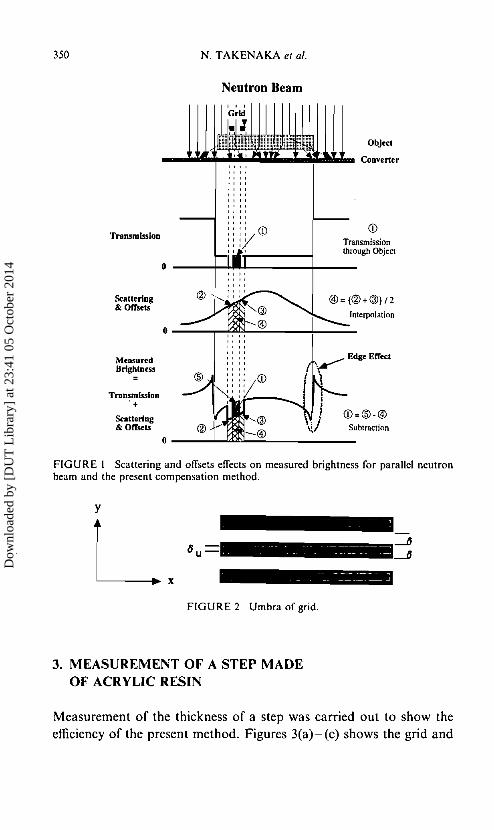
The umbra method was modified to measure both S(x,y) andO(x, y) in one image in sacrifice of the spatial resolution. A grid madeof B4C was placed between the object and the source. The image withthe grid was not compared with the image without it in the previousmethods [6,7] but both values of S(x,y) and O(x,y) were determinedby spatial interpolation in the image with the grid. The compensationmethod is illustrated schematically in Figure I.
The compensated attenuation term, {S(x,y)-O(X,y)}Cf is estimatedby the image calculation as
{S(x,y) _ O(x'Y)}c = IS(x,y) _S(x,y + 0) ; S(x,y - 0) I (6)
where 0 is the width and the interval of the tape of the grid.Compensated values can be calculated when the measurement position(x,y) is in the umbra and the positions (x,y+8) and (x,y-o) as shownFigure 2.
The width of the umbra ou is estimated as
ou = 0 - 2z/(L/D) (7)
where z is the distance between the grid and the converter. The value0= 3 mm was employed. When the object size is less than ISO mm, theumbra width is I mm for LID = ISO, the value of JRR-3M. The twodimensional quantitative void fraction distribution can be measuredby Eq. (4) after calculating the compensated attenuation terms in Eqs.(1)-(3) by Eq. (6) though the spatial resolution in y direction is reduceto 3 mm and the image information decreases to less than 1/3.
Dow
nloa
ded
by [
DU
T L
ibra
ry]
at 2
3:41
05
Oct
ober
201
4
350 N. TAKENAKA et al.
Neutron Beam
Interpolation
Object
CD
Subtraction
Transmissionthrough Object
CD=®-®
__w...~......a;WI"'''''o1I;r,aIIiI_. Converter
Transmission
0
Scattering& Offsets
0
Measun:dBrightness
Transmission+
Scattering& Offsets
0
FIGURE I Scattering and offsets effects on measured brightness for parallel neutronbeam and the present compensation method.
-- -----~- - ---'
y
L. '.=FIGURE 2 Umbra of grid.
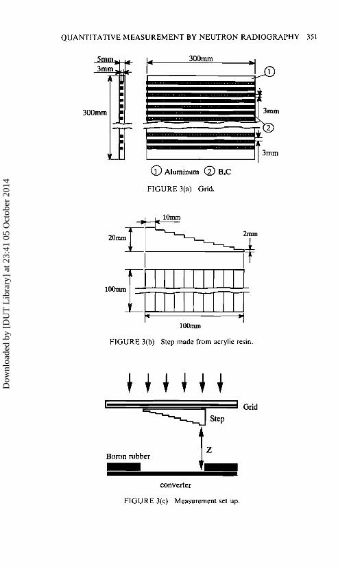
3. MEASUREMENT OF A STEP MADEOF ACRYLIC RESIN
Measurement of the thickness of a step was carried out to show theefficiency of the present method. Figures 3(a)-(c) shows the grid and
Dow
nloa
ded
by [
DU
T L
ibra
ry]
at 2
3:41
05
Oct
ober
201
4
QUANTITATIVE MEASUREMENT BY NEUTRON RADIOGRAPHY 351
300mrn
1
3mrn
1__t~m(i) Aluminum CV S.C
FIGURE 3(a) Grid.
FIGURE 3(b) Step made from acrylic resin.
converter
FIGURE 3(c) Measurement set up.
Dow
nloa
ded
by [
DU
T L
ibra
ry]
at 2
3:41
05
Oct
ober
201
4
352 N. TAKENAKA et al.
the step tested for the present report and illustration of the set up forthe measurement. The rods of the grid was made from B4C finepowder less than 5 urn filled in thirty rectangular ducts 3 mm x 3 mmmachined in an aluminum plate 5 mm in thickness. The step was madeof acrylic resin and its thickness was varied from 2 mm to 20 mm witha 2 mm interval. They are machined within 10urn tolerance. Thedistance, z, between the converter and the step was varied from 0 to9 mm by a remote-controlled traverser.
A cooled-CCO camera system at the JRR-3M in JAERI was usedfor the measurement. The exposure time was 6 seconds. Themathematical morphological filter [10] and the minimum filter wereused to reduce starlike noises due to the direct irradiation ofradioactive rays to the CCO elements. Two series of measurement ofthe step thickness with and without the grid were carried out bychanging the distance z from 0 to 9 mm. When the grid was used theconverter around the step was masked by a boron rubber plate 10mmin thickness to reduce the effects of the optical rays generated at theconverter without the object as shown in Figure 3(c).
The brightness of the step images is expressed as
Ss(x,y) = G(x,y)exp[-psJ.Lmsts(x,y)] + Os(x,y) (8)
The brightness without the step
S(x,y) = G(x,y) + O(x,y) (9)
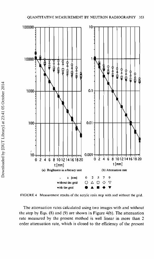
both with and without the grid, were also measured.Measured values of the brightness of each step thickness in arbitrary
unit are shown in Figure 4(a) with the distance z between the step andthe converter as the parameter. The brightness without the grid andthe compensated brightness with the grid by Eq. (4) are shown. It canbe seen from the data that the brightness without the grid is higherthan the measured value with grid by the offset terms due to thescattering effects. With increasing the distance z between the converterand the step, the effects of the scattered neutrons are decreased but theother effects to the offsets terms are not negligible without the presentmethods using the grid.
Dow
nloa
ded
by [
DU
T L
ibra
ry]
at 2
3:41
05
Oct
ober
201
4
QUANTITATIVE MEASUREMENT BY NEUTRON RADIOGRAPHY 353
(b) Attenuation rate
2468101214161820t [mm]
Nr\
\\
\\
\\
\\
10
0.1
0.01
0.0018101214161820 0t[mm]
(a) Brightness inarbitrary unit
\\
\\
\
\\\
~
\
10o 2 4 6
100
1000
10000
100000
z [em]
without the grid
withthe grid
o 2 5 7 9
o L:> 0 <> 'V'• & •• ~
FIGURE 4 Measurement results of the acrylic resin step with and without the grid.
The attenuation rates calculated using two images with and withoutthe step by Eqs. (8) and (9) are shown in Figure 4(b). The attenuationrate measured by the present method is well linear in more than 2order attenuation rate, which is closed to the efficiency of the present
Dow
nloa
ded
by [
DU
T L
ibra
ry]
at 2
3:41
05
Oct
ober
201
4
354 N. TAKENAKA et 01.
machining. Since the offset term at one point compensated by thepresent methods affected by the other points as shown by Eq. (5), alittle more discussion is required to speak about the measurementaccuracy of the void fraction in two-phase flow by the present method.
4. CONCLUSIONS
Quantitative measurement methods by neutron radiography weresummarized. For the TV system the effects of the scattered optical raysshould be considered. A method using an neutron absorber grid basedon the umbra method was proposed to for the two-dimensionalquantitative measurement with one image in sacrifice of the spatialresolution.
References
[I] Glickstein et 01. (1992). Trans. ANS/ENS, 66, 591-593.[2] Hirdlika and Peterka (1990). In: "Neutron Radiography (3)", Kluwer Acad. Pub.,
pp.131-143.[3] Hibiki el 01. (1993). J. Nuel. Sci. Tech., 30,15-22.[4] Yoshii and Kobayashi (1996). Nuel. Instr and Meth., A377, 76-79.[5] Tarnaki et 01., In: "Neutron Radiography (4)", Gordon and Breach Sci. Pub.,
pp. 837- 844.[61 Kobayashi et 01. (1991). Proc. lSI JSM E/ASME Int. Coni 011 Nuelear Engineering,
1,649-654.[71 Murata et 01. (1992). In: "Neutron Radiography (4)", Gordon and Breach Sci. Pub.,
pp. 583-590.[81 Takenaka er 01. (1996). Proc. 51h Wid' Coni Neutron Radiography, pp. 118-125.[9] Takenaka et 01. (1999). Proc. 3rd Top. Meet. Neutron Radiography, Nuel. lnst.
Meth., A424, 73-76.[10] Motomura et 01. (1996). Nuel. lnst. Meth., A377, 93-95.D
ownl
oade
d by
[D
UT
Lib
rary
] at
23:
41 0
5 O
ctob
er 2
014