a magnetometer for the measurement of the earth's...
TRANSCRIPT
434
A Magnetometer for the Measurement of the Earth's Vertical Magnetic Intensity inC.G.S. Measure.
By D. W. Dye, D.Sc. (of the National Physical Laboratory).
(Communicated by Sir Arthur Schuster, F.R.S.—.Received August 18, 1927.)
I. Introduction.
The measurement of the vertical component of the earth’s magnetic field is a less simple operation than that of the horizontal component.
The horizontal field measurements are on a satisfactory basis, whether made by the swinging magnet method, or by the more recently developed electric magnetometers, in which known magnetic fields may be provided by means of known currents flowing through coils of known dimensions.
In the horizontal intensity magnetometers an indicating system is suspended or supported so that it can turn about a truly vertical axis. In a vertical intensity instrument, the corresponding suspension of an indicating device about a truly horizontal axis is by no means so simple.
At present, therefore, vertical intensity measurements are deduced indirectly from horizontal intensity measurements combined with measurements of the angle of dip. This latter quantity cannot be measured with very great precision, and the accuracy of the finally deduced vertical intensity becomes less as the angle of dip becomes greater towards the magnetic poles.
The advantages of a direct method of measuring vertical intensity need no stressing; quite recently a novel absolute vertical intensity magnetometer has been developed by D. La Cour in Denmark (‘ Terrestrial Magnetism,’ vol. 31, p. 153, 1926).
In this instrument a large, flat circular coil is turned about a horizontal axis from one position with its plane horizontal to the other similar position displaced 180° from the first. The flux linkage so produced is balanced by the flux linkage with the secondary winding of a mutual inductance when a known current change is made in the primary winding.
From the published information on the instrument, the method appears to have considerable value and the accuracy attainable will doubtless be improved by further development.
The vertical intensity magnetometer forming the subject of the present paper makes use of the principle of balancing the vertical component of the
on June 13, 2018http://rspa.royalsocietypublishing.org/Downloaded from
Measurement o f Earth's Vertical Magnetic Intensity. 435
earth's field by a vertical field produced by a steady current passing through a Helmholtz coil system. Some possibilities in this direction have been indicated by F. E. Smith in his description of the horizontal force magnetometer developed at the National Physical Laboratory (F. E. Smith, ‘ Phil. Trans.,’ A, vol. 223), along the principle first described by A. Schuster (£ Terrestrial Magnetism,’ 1914). This principle applied to the horizontal intensity measurements was to orient the Helmholtz coil about a vertical axis and to observe the angle at which H — F cos a, where F is the actual field produced at the centre of the coil and a is the angle which its horizontal axis makes with the magnetic meridian.
This principle could have been applied to a vertical force magnetometer, but the difficulties of determining when the resultant small field is truly horizontal are great. The direct annulment of the earth’s vertical field appears to be a more satisfactory principle.
The principle of the magnetometer is carried into effect by setting up the Helmholtz coil system with its axis truly vertical. The measurement consists in adjusting and measuring the current through the coil system at that exact value necessary to produce a field equal and opposite to the earth’s vertical component.
One of the most important features of such a method is the means whereby the exact annulment is observed.
There are a number of possibilities ; for example :—
(a) A small exploring coil may be rotated about a horizontal axis which mustbe directed very precisely along the magnetic meridian.
The electromotive force induced in such a coil will become zero, at every instant, when the vertical component of the resultant magnetic field is zero, since it is then directed along the meridian and is parallel with the axis of rotation of the exploring coil.
The condition of zero-induced electromotive force may be observed either on a direct current galvanometer, by the help of a commutator on the coil spindle, or it may be observed on a vibration galvanometer, tuned to a frequency resonant to the rate of revolution of the coil.
(b) A small indicating magnet might be suspended about a horizontal axiswith its magnetic axis horizontal as in a vertical force magnetograph. The difficulties of using such a system are great, and the uncertainties regarding the conditions of balance consequent upon a gravity torque cannot easily be reduced to small quantities.
on June 13, 2018http://rspa.royalsocietypublishing.org/Downloaded from
436 D. W. Dye.
(c) A flat coil can be pivoted or suspended so that its plane is vertical and so that it can deflect about a horizontal axis. If a steady current is sent through the coil, a deflection will result. The deflection will become zero when the vertical field is zero.
( d) A very light coil can be suspended so that it may vibrate about a horizontal axis in a similar manner to a coil-type vibration galvanometer. If such a coil is supplied with alternating current of the same frequency as that of its free resonant vibration, it is very sensitive to a magnetic field in a suitable direction.
It is probable that any of these methods could be made satisfactory from the point of view of sensitivity, convenience and accuracy, and some of them have been tried.
The method actually developed finally has been that outlined under (d), using a vibrating coil.
The reasons for choosing this method are—(1) No revolving parts are required in the apparatus in the magnetic field provided by the Helmholtz system, and (2) no delicate pivoting or suspension of the detecting device is necessary. The control forces required to give the vibrating coil a convenient resonant vibration frequency are relatively large, so that its statical position is located with great certainty and constancy.
II. Principle of the Magnetometer.The principle of the magnetometer is therefore carried into effect as follows
The Helmholtz coil system is set up with its axis truly vertical. At the centre of the system a small, flat and very light coil is suspended about an axis of vibration. The plane of the coil is vertical, and its axis of vibration is horizontal. The coil is mounted in a frame in such a manner that these two conditions may be very nearly satisfied.
A relatively large alternating current at the frequency of resonant vibration is sent through the vibrating coil. Under these conditions a large vibration results from the inter-action between the alternating current and the earth’s vertical magnetic field. This vibration is reduced to zero when the applied vertical field exactly annuls the earth’s vertical component. The determination of Y consists in observing the current required to give an exact condition of rest or balance on the vibrating coil. This current multiplied by the calculated or otherwise determined constant of the Helmholtz coil gives the value of V in C.G.S. measure corresponding to that reading.
on June 13, 2018http://rspa.royalsocietypublishing.org/Downloaded from
Measurement o f Earth’sVertical Magnetic Intensity. 437
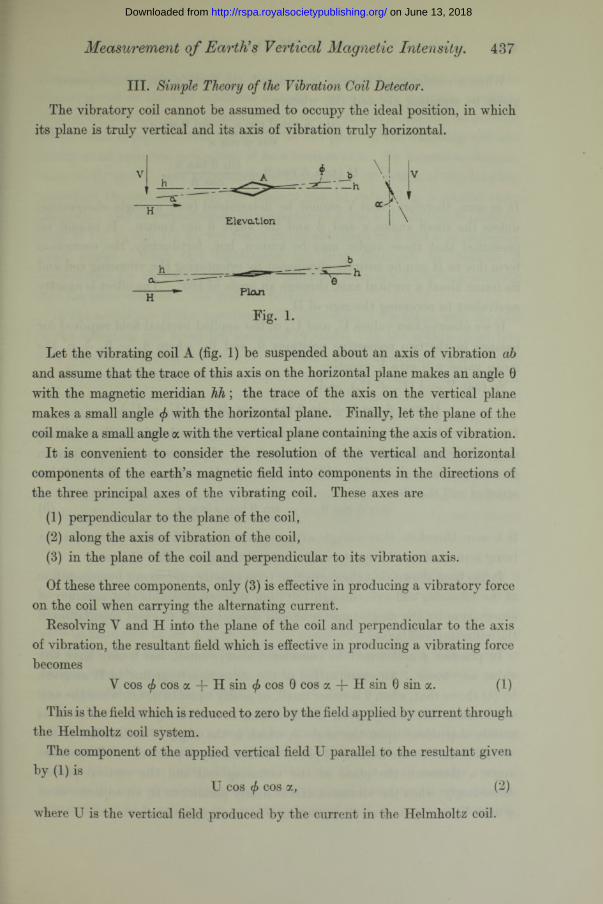
III. Simple Theory of the Vibration Coil Detector.The vibratory coil cannot be assumed to occupy the ideal position, in which
its plane is truly vertical and its axis of vibration truly horizontal.
b
Plan
Fig. 1.
Let the vibrating coil A (fig. 1) be suspended about an axis of vibration ab and assume that the trace of this axis on the horizontal plane makes an angle 0 with the magnetic meridian h h ; the trace of the axis on the vertical plane makes a small angle <f> with the horizontal plane. Finally, let the plane of the coil make a small angle a with the vertical plane containing the axis of vibration.
It is convenient to consider the resolution of the vertical and horizontal components of the earth’s magnetic field into components in the directions of the three principal axes of the vibrating coil. These axes are
(1) perpendicular to the plane of the coil,(2) along the axis of vibration of the coil,(3) in the plane of the coil and perpendicular to its vibration axis.
Of these three components, only (3) is effective in producing a vibratory force on the coil when carrying the alternating current.
Resolving Y and H into the plane of the coil and perpendicular to the axis of vibration, the resultant field which is effective in producing a vibrating force becomes
Y cos f cos a + H sin </> cos 0 cos a + H sin 0 sin a. (1)
This is the field which is reduced to zero by the field applied by current through the Helmholtz coil system.
The component of the applied vertical field U parallel to the resultant given by (1) is
U cos (f> cos a, (2)
where U is the vertical field produced by the current in the Helmholtz coil.
on June 13, 2018http://rspa.royalsocietypublishing.org/Downloaded from
438 D. W. Dye.
When a condition of balance is obtained, the earth’s vertical component is given by equating (1) and (2), whence
V ” (31
It is seen, therefore, that V cannot be determined from a single observation unless the small angles a and (f> and the angle 6 are known. It cannot be presumed that these angles may be known, but, fortunately, the correction term due to H can be entirely eliminated by orientating the vibrating coil and its frame about a vertical axis, through an angle of 180°. The effect is exactly equivalent to reversing the sign of H.
If we observe two values Uj and U2 of the applied vertical field required for balance in the two respective positions 0X and 02, where 02 = 0X -j- tu, the mean value will give V exactly.
By means of levelling screws on the frame carrying the vibrating coil, an adjustment of the small angles (f> and a can be made. By successive observations in the two positions giving TJ-l and U2 we can make Uj — U2 zero. The condition satisfied will then be
It is seen, therefore, that a single adjustment of this kind cannot ensure cf> and a being zero or of small importance for a small change in either of them.
It has been shown that the correction term exactly cancels out by orientation of the vibrating coil axis through 180°, but it is not desirable that accuracy of observation by the magnetometer should depend upon an exact orientation of the vibrating coil axis.
In practice </> and a may be considered always small, but 0 may have any value we choose. An examination of the correction term due to H as given by (4) shows that, when 0 is either small, or nearly equal to tt, when the axis of vibration lies nearly along the meridian, the vibratory force due to H is mainly dependent upon the angle </>, which is the angle of inclination of the vibration axis to the horizontal plane. I t is hardly dependent at all upon the angle a (between the plane of the vibrating coil and the vertical plane). Accordingly, when the vibration axis is nearly parallel to H, an adjustment of </> until Uj = U2 must result in causing </> to be very small indeed.
So that V = \(Uj + U2), andII (tan (f) cos 0 -(- sin 0 tan a/cos </>) = ^ (Uj — U2).
tan </> cos 0 = — sin 0 tan a/cos <f>. (5)
on June 13, 2018http://rspa.royalsocietypublishing.org/Downloaded from
Measurement o f Earth's Vertical Magnetic Intensity. 439
Again, suppose two values U3 and U4 are observed, with the axis of the vibrating coil in the two positions at right angles to the magnetic meridian (0 = 1/2 71 and 3/2 77), the vibrating force due to H will be mainly on account of the small departure from verticality of the plane of the vibrating coil and hardly at all upon the inclination of its vibration axis. By successive observations of U3 and U4 and adjustment of the angle a by means of the levelling screws on the coil mounting, the angle a can be reduced to a second order quantity. One or two alternate adjustments of </> and a by successive observations of Uj, U2 and U3, U4 will result in the reduction of and a to negligibly small angles. When this adjustment has been obtained, the balance is undisturbed for all values of 0. The vibration axis can be in any azimuth and the same value of U will give the balance.
In the actual use of the instrument the observations are taken with the axis of the vibrating coil along the meridian (0 small). In the nature of its construction the vibrating coil is liable to small variations in the angle a, which its plane makes with the vertical, blit the angle <f> is not apt to change much, since the suspensions are under considerable tension and so define the axis of vibration with precision and constancy. When 0 is nearly 0 or small variations in a do not affect the balance.
Errors of the Method.—When making the observations there will be a small uncertainty in the orientation of the vibration axis, so that if 0 is 0 in one position it will be tz + A0 in the second position instead of 7c. The mean of the tworeadings Uj and U2 will then give a value for V which is in error by the amount
HaA0.
The procedure in the adjustments outlined above will enable the angle a to be reduced to 1/1000 radian with certainty. In order that the error Ha A9/V may not be greater than one part in a hundred thousand it will only be necessary to set 0 to an accuracy equivalent to V/100 H. Actually 0 can be set to an accuracy at least as high as 1 /1000 radian, so that except in regions near the magnetic equator, where V/H will be small, there will not be any appreciable error due to A0.
Two other sources of error arise in the adjustment of the instrument, due (a) to errors in setting the axis of orientation truly vertical and ( ) in setting the axis of the Helmholtz coil parallel to this axis. These errors are dealt with in a short appendix, from which it will be seen that a small angular error ^ between the axis of orientation and the vertical will introduce an error into the measurement of Y, which at its maximum is equal to H It is seen, therefore,
on June 13, 2018http://rspa.royalsocietypublishing.org/Downloaded from
440 D. W. Dye.
that this error is in the first order of small quantities. The axis of orientation must therefore be set vertical with great precision. The instrument is provided with very sensitive levels, and the turntable, which virtually defines the vertical axis of orientation, revolves on a ball race of large diameter. A careful test showed that the departure from verticality of the axis was certainly not greater than 1 part in 50,000 and was probably less than half this amount.
IY. Description of the Magnetometer.(a) Helmholtz Coil System.—This system comprises the same marble cylinder
which forms the essential part of the horizontal force magnetometer described very fully by F. E. Smith in the paper previously referred to. For full details of the measurements of the diameter and pitch of the windings, etc., the reader is referred to that paper. The variations of the radial and axial fields of the coil over a region near its centre have also been fully investigated and need not be discussed here. I t will suffice to say that within a sphere of 2 cm. diameter the maximum difference in axial intensity from that at the centre of the system is less than 4 parts in 106.
The calculated constant of the coil system is
U( = 3-59595 ^(1 — 7-9 X 10~6 — 17]),
where Ut is the axial magnetic force in C.Gr.S. units when the cylinder is at the temperature t° C.
i is the current in absolute measure.The constant -j- 7-9 X 10~6 is the measured thermal expansion coefficient
of the marble in length and diameter. The constant 3 • 59595 is believed to be accurate to 1 part in 105 from the measured dimensions. This value refers to the dimensions measured in 1921. These may have slightly altered since then, but the present observations are on the assumption of unchanged dimensions.
The Original base and turntable have been used in the present magnetometer, but in order to support the cylinder with its axis vertical, a non-magnetic bronze platform has been made to fit, on its under side, the existing cradles on the turntable, and to provide on its upper surface three levelling and three centering screws for the support and adjustment to verticality of the marble cylinder.
The general appearance of the magnetometer will be seen by reference to the photograph, fig. 2, in which the triangular stiff platform can be seen. The turntable is provided with an accurately engraved angular scale, whereby it may be set in azimuth at any desired angle to an accuracy of a few seconds of arc.
on June 13, 2018http://rspa.royalsocietypublishing.org/Downloaded from
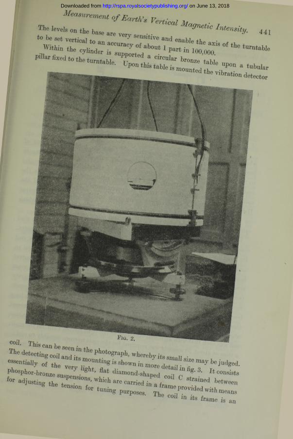
I___________* * • ' - % <4,to be set vertical } sensitive and enable +1,
„w i t w n « - 1 ^ » w o ,o o 7 of the turntaw e. t n b n I a r
— ------ t<5d vlbr«ion detector
coil *
Tie detecting cod 7 7 ^ Pb°tognPb’ whereby its sm „ .
■” ■ * * . * •• cod in its frame
an
on June 13, 2018http://rspa.royalsocietypublishing.org/Downloaded from
442 D. W. Dye.
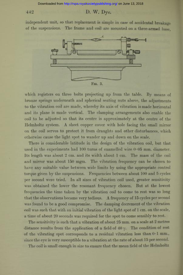
independent unit, so that replacenent is simple in case of accidental breakage of the suspensions. The frame and coil are mounted on a three-armed base,
Fig. 3.
which registers on three bolts projecting up from the table. By means of bronze springs underneath and spherical seating nuts above, the adjustments to the vibration coil are made, whereby its axis of vibration is made horizontal and its plane is made vertical. The clamping arrangements also enable the coil to be adjusted so that its centre is approximately at the centre of the Helmholtz system. A sheet copper cover with hole facing the. small mirror on the coil serves to protect it from draughts and other disturbances, which otherwise cause the light spot to wander up and down on the scale.
There is considerable latitude in the design of the vibration coil, but that used in the experiments had 100 turns of enamelled wire 0-05 mm. diameter. Its length was about 2 cm. and its width about 1 cm. The mass of the coil and mirror was about 150 mgm. The vibration frequency can be chosen to have any suitable value between wide limits by using the appropriate control torque given by the suspensions. Frequencies between about 100 and 5 cycles per second were tried. In all sizes of vibration coil used, greater sensitivity was obtained the lower the resonant frequency chosen. But at the lowest frequencies the time taken by the vibration coil to come to rest was so long that the observations became very tedious. A frequency of 15 cycles per second was found to be a good compromise. The damping decrement of the vibration coil was such that with an initial vibration of the light spot of 1 cm. on the scale, a time of about 20 seconds was required for the spot to come sensibly to rest.
The sensitivity is such that a vibration of about 25 mm. on a scale at 2 metres distance results from the application of a field of 40 y. The condition of rest of the vibrating spot corresponds to a residual vibration less than 0*1 mm., since the eye is very susceptible to a vibration at the rate of about 15 per second.
The coil is small enough in size to ensure that the mean field of the Helmholtz
on June 13, 2018http://rspa.royalsocietypublishing.org/Downloaded from
Measurement o f Earth’,s Vertical Magnetic Intensity. 443
system over the region occupied by it does not differ from that on the axis by more than 2 parts in 106.
(b) Auxiliary Apparatus.—The auxiliary apparatus necessary to the magnetometer, in addition to galvanometer lamps, scales and batteries, are—
(1) a small source of alternating current at a frequency of about 15 cycles per second,
(2) means of measuring and adjusting the Helmholtz coil current to a highdegree of accuracy.
(1) Various sources of alternating current were tried. These included a self- maintained tuning fork, a valve oscillator, and an alternator. Of these only the alternator proved satisfactory. The reason of this was that, with the other sources, a perfect balance was unobtainable, even when the magnetic field had been exactly compensated. A residual vibration of 15 or 20 mm. resulted when either a tuning fork or valve oscillator was used as source. This was puzzling at first, but was ultimately found to be due to heating effects of the current. The vibration coil is very small in surface, and, in order to obtain sensitivity, it is necessary to send a relatively large current through it (70 milliamperes). The energy dissipated in the coil is about 0-2 watt. Owing to an inevitable dissymmetry of the coil, the alternate heating and cooling of each cycle sets up a small vibratory force, which, of course, is quite independent of the magnetic field in which the coil is supported. With a symmetrical wave form, however, the heating and cooling should have a frequency twice that of the source, and hence at the most should produce only a minute forced vibration at the double frequency, since the vibration coil is completely out of tune to this frequency. The case is, on the other hand, otherwise if harmonics of frequency 2 n are present. An unsymmetrical wave form results so that the heating during one half-wave is not equal to that during the next half-wave. A vibra- tive force at the resonant frequency will result and will cause a residual vibration which cannot be reduced to zero by any adjustment of the magnetic field. Various kinds of circuits were tried, but no absolutely perfect balance could be obtained with any other source than an alternator. With almost any kind of alternator, however, a perfect balance can be obtained. The actual alternator used was a small machine used as a rotary converter run from a 6-volt battery. W ith the ball bearings and special brushes supplied the current taken was only 0-4 amp.
It was provided with a governor of the frictional gramophone type, in order that the speed might keep sufficiently constant to remain sensibly
VOL. CXVII.— A. 2 H
on June 13, 2018http://rspa.royalsocietypublishing.org/Downloaded from
444 D. W. Dye.
synchronous with the frequency of the vibrating coil. At the normal speed the root mean square voltage was about 4. This voltage provided 70 milli- amperes in the vibrating coil. The speed continually varied slightly in use, but this did not matter in practice, since the condition of a slight want of balance on the vibration coil always showed itself when the observation was continued for one minute. The small alternator behaved very satisfactorily throughout the experiments. In general, it was only necessary to adjust the speed once or twice during a run of about an hour and a half. In some cases the whole run was made without any readjustment.
(2) Measurement of Current.—The current measurement was made in some cases by a straightforward potentiometer method using a standard resistance coil of 1 ohm resistance. This method is very flexible, as it will allow measurements in any part of the world with the one set up, but requires the potentiometer and necessitates repeated adjustment of the potentiometer current during a run. In the later runs the independent potentiometer was dispensed with and was replaced by a direct potentiometer method, whereby part of the potential difference on the resistance combination was balanced against a standard cell. The most convenient arrangement for this is as shown in fig. 6 in Appendix II, in which the corrections and calibration of the current-measuring system are discussed.
In all cases where observations are made at a fixed station, the direct potentiometer method has much to recommend it. I t can readily be adapted to give direct readings of the change in Y over a range of a few parts in a thousand.
On an instrument intended to be used at places widely separated, where Y might have values ranging from0 to 0*6 C.G-.S. units, a separate potentiometer system would be much more flexible but not quite so accurate.
V. General Arrangement of the Apparatus.The general layout of the magnetometer and its auxiliaries is as shown
in fig. 4. The current-measuring system shown in the figure was that actually used, but the scheme suggested in Appendix II is preferable and will be used on future occasions.
The Helmholtz coil system CC is set up about the vertical axis ab. Its windings are supplied with current from a 20-volt battery Vr Rough adjustment is provided by a three-dial rheostat P with good contacts and carrying capacity for the current of about 1 • 2 amp. The current-measuring arrangements actually used consisted of standard resistance combination Rt of about 0*8 ohm in series with standard resistance R2 of 0-01 ohm. R2 was shunted
on June 13, 2018http://rspa.royalsocietypublishing.org/Downloaded from
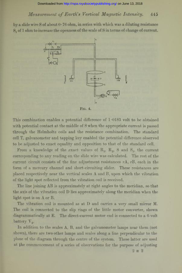
by a slide wire S of about 0*76 ohm, in series with which was a diluting resistance Sj of 1 ohm to increase the openness of the scale of S in terms of change of current.
Measurement o f Earth's Vertical Magnetic Intensity. 445
Fig. 4.
This combination enables a potential difference of 1-0183 volt to be obtained with potential contact at the middle of S when the appropriate current is passed through the Helmholtz coils and the resistance combination. The standard cell T, galvanometer and tapping key enabled the potential difference observed to be adjusted to exact equality and opposition to that of the standard cell.
From a knowledge of the exact values of Rj, R 2, S and S15 the current corresponding to any reading on the slide wire was calculated. The rest of the current circuit consists of the fine adjustment resistances rB, each in the form of a mercury channel and short-circuiting slider. These resistances are placed respectively near the vertical scales A and B, upon which the vibration of the light spot reflected from the vibration coil is received.
The line joining AB is approximately at right angles to the meridian, so that the axis of the vibration coil D lies approximately along the meridian when the light spot is on A or B.
The vibration coil is mounted as at D and carries a very small mirror M. The coil is connected to the slip rings of the little motor converter, shown diagrammatically at E. The direct-current motor end is connected to a 6-volt battery V2.
In addition to the scales A, B, and the galvanometer lamps near them (not shown), there are two other lamps and scales along a line perpendicular to the plane of the diagram through the centre of the system. These latter are used at the commencement of a series of observations for the purpose of adjusting
2 h 2
on June 13, 2018http://rspa.royalsocietypublishing.org/Downloaded from
446 D. W. Dye.
the plane of the vibration coil to its electrically vertical position. The actual observations are taken only on scales A and B alternately.
In the actual experiments made at the laboratory the direct current measuring apparatus and battery Vx were, for convenience, in the main building, whilst the magnetometer itself was in a special hut removed from local magnetic disturbances arising within the laboratory.
The motor converter and its battery V2 were set up just outside the hut at a distance of about 4 metres from the magnetometer. I t was so arranged that the vibration of the light spot was visible through the doorway when adjusting the governor and speed of the converter to that corresponding to resonance of the vibration coil.
A test was made to determine the stray field, produced by the permanent magnets of the motor converter, at the centre of the magnetometer. With the position of the converter such that the stray field was vertical, it was found to be equal to about 5 y at 4 metres distance. By turning the converter so that the stray field is horizontal, therefore, the error becomes quite negligible.
A vertical force magnetograph for recording continuously the changes in Y during a series of observations on the magnetometer was constructed and set up.
The instrument consisted of a cobalt-steel magnet 5 mm. diameter and 20 mm. long. The magnet was mounted transversely on a brass spindle provided with adjustable gravity control weights at right angles to one another and to the spindle. Thin phosphor-bronze suspensions attached one to each end of the spindle, and lightly strained in line to supports on a base, formed the horizontal axis of suspension.
A damping vane between copper plates served to render the system just aperiodic. The gravity control was adjusted to be nearly equal and opposite to that due to the vertical component acting on the magnet. The control force was finally adjusted by means of a small magnet which provided a weak horizontal field directed along the magnetograph magnet axis.
The image of a Nernst filament formed by reflection from a mirror on the magnet fell on a narrow horizontal slit, having first passed through a prism to turn the movement of the reflected ray into a horizontal plane. A long band of photographic paper slowly revolving behind the slit recorded the variations in V.
The sensitivity was such that a displacement of about 1 mm. wTas produced by a field change of 1 y.
The photographic paper moved at the rate of about 40 cm. per hour.
on June 13, 2018http://rspa.royalsocietypublishing.org/Downloaded from
The effect of the magnetograph magnet upon the magnetometer was quite negligible at the distance of 4 metres which separated them.
VI. Experimental Observations with the Magnetometer.
(a) Adjustments.—Having made a few preliminary runs in order to gain experience in the use of the instrument, it was set up in the magnetic hut in the laboratory grounds.
It was soon seen both by the magnetometer and by the magnetograph record that accurate observations were impossible during the daytime owing to train and tram disturbances. Continuous, rapid, and very large excursions (up to 100 y magnitude) occurred all the time. The accurate runs were therefore made at night during the hours of 1.30 and 4.0 a.m.
The turntable was first levelled as accurately as possible, using the sensitive levels on it. The resulting position of the axis of turning was vertical to a probable accuracy of 1 /50,000 radian.
The marble cylinder was then centred and levelled on its platform by the aid of a dial gauge which could indicate an eccentricity of 0-01 mm. The gauge was held in a rigid clamp so that its foot pressed against the outer cylindrical surface of the cylinder. By alternate observations at the lower end of the cylinder and adjustment of the centring screws, followed by observations at the upper end and adjustment of the levelling screws, the cylinder was brought into a truly concentric position with respect to the axis of turning.
The galvanometer lamps and scales were then adjusted so that the image of the cross wires on the lamp lens formed after reflection from the small mirror on the vibration coil (at rest) fell on definite lines on the scales, thus locating the two positions of the vibration coil axis approximately along the magnetic meridian. The other two lamps and scales were set up and adjusted to correspond to positions of the axis of D at right angles to the meridian. The current having been switched on and having become steady, the next adjustments made were those of the vibration coil. The light spot was brought to position on scale A and the mercury rheostat rA was adjusted until balance was obtained. The magnetometer was then oriented round until the light spot was on scale B. A small vibration of the light spot resulted. By temporary adjustment of rB for balance, an estimate of the difference in current for balance in the A and B positions was obtained. The rheostat rB was then placed midway between its new and old positions. The vibration, now reduced to about half its original value, was reduced to zero by adjustment of the axis of vibration of the coil by means of the appropriate levelling screw on D.
Measurement o f Earth's Vertical Magnetic Intensity. 447
on June 13, 2018http://rspa.royalsocietypublishing.org/Downloaded from
448 D. W. Dye.
A similar procedure was carried through with the vibration coil axis in the two E.W. directions, except that adjustment to equality was now made by adjustment of the plane of the vibrating coil.
After one or two repetitions of each of the above adjustments, a condition was arrived at such that for any of the four positions of orientation of the vibrating coil axis the current for balance was the same to within 2 or 3 parts in 10,000.
These adjustments satisfactorily completed, the actual observations constituting a run were made as follows :—
(b) Observations.—(i) A calibration of the magnetograph was made by meansof a known small current passed through a two-turn coil in a horizontal plane centrally disposed around the small suspended magnet constituting the essential part of the magnetograph. This current was such that a change of 25 y was made in the vertical field. The sensitivity of the magnetograph was such that a deflection of its recording light spot of about 30 mm. resulted. The calibrating field was applied in both positive and negative directions.
(ii) The magnetometer was brought into the A position and balance of the light spot obtained by adjustment of rA. The light spot had crossed lines on it and was observed with a lens. I t was found possible to obtain a balance of great sharpness. The vibration at 15 cycles per second is peculiarly susceptible to the eye, and the condition of rest, when obtained, corresponded to a vibration less than 0 • 1 mm. amplitude. Under the steady conditions appertaining to the night observations and on a magnetically quiet occasion, the balance remained sensibly perfect for a minute or more at a time.
(iii) When the balance had been obtained and was seen to be real and steady, a signal by means of a tapping key and lamp was given to an observer stationed at the current-measuring apparatus. He, forthwith, adjusted the slider on S until a balance on galvanometer G was obtained. The reading on S was noted and the time at which the signalling flash occurred was also entered.
Simultaneously with the flashing signal to the observer a locating signal was given to the recording magnetograph. This signal took the simple form of lighting a lamp, at a distance of about 10 feet, in front of the narrow slit in the box containing the photographic paper, upon which the magnetograph record was in course of exposure. This signal gave a fine line on the record and identified on it the instant at which the magnetometer observation was made.
(iv) The magnetometer was turned to the B position and the procedure as outlined under (6) and (c) was carried out, the adjustment of current being made by means of rB.
on June 13, 2018http://rspa.royalsocietypublishing.org/Downloaded from
A complete series of observations alternately on A and B was thus made throughout a period of about one and a half hours. During such a period between 30 to 40 observations were made.
At a few intervals, readings of the temperature of the marble cylinder of the magnetometer were made and of the standard resistance coils Rl5 R 2. The standard cell was in an oil bath in a vault and remained absolutely steady throughout a run.
During the run observations were made to see that the rotary converter was remaining in tune with the vibrating coil. In order to ascertain this, one of the rheostats rA or rB was offset so as to produce a change in current sufficient to give several centimetres vibration of the light spot. I t was then seen whether this vibration was as large as it should be. If it was small, a readjustment of speed was made. In general the small unavoidable variations of speed were such that the vibrating coil continually went into and out of tune, so that the vibration varied from a maximum to about one-half of this value. During any period of one minute, however, the light spot nearly always reached an amplitude nearly equal to its maximum amplitude. I t was only occasionally, therefore, that an observation was in error owing to insensitivity resulting from the vibrating coil being out of tune.
In the course of every observation a small displacement equivalent to about 1 part in 104 in current was made, and a reading was not accepted unless the resulting small vibration was visible.
At the conclusion of a series of observations, a second calibration of the magnetograph was made.
The observations when obtained were dealt with as follows:—From a knowledge of Rx, R2, S and S15 a factor was determined for converting differences from an arbitrarily chosen reading on S into differences in y units from the base line value corresponding to the arbitrary reading.
These values of y differences were entered opposite the corresponding S readings for the alternate A and B observations numbered in sequence 1, 2, 3, etc.
The values for the mean of each pair of observations, 1 and 2, 2 and 3, 3 and 4, etc., were then taken. These are the final V differences corresponding to the mean value of B at the instants 1 and 2, 2 and 3, etc.
The displacements from an arbitrary base line on the magnetograph record were next read off the record at the instants 1, 2, 3, etc. These, converted to y differences, were then treated similarly to the magnetometer readings so as to give the mean values for the readings 1 and 2, 2 and 3, etc.
Measurement o f Earth's Vertical Magnetic Intensity. 449
on June 13, 2018http://rspa.royalsocietypublishing.org/Downloaded from
450 D. W. Dye.
Finally, the differences between the magnetograph and the magnetometer deduced values of “y difference ” were taken. These latter should, of course, under ideal conditions, be quite constant. The variations in these differences give a measure of the uncertainty in any reading resulting from all the uncertainties in the chain of observations connecting them.
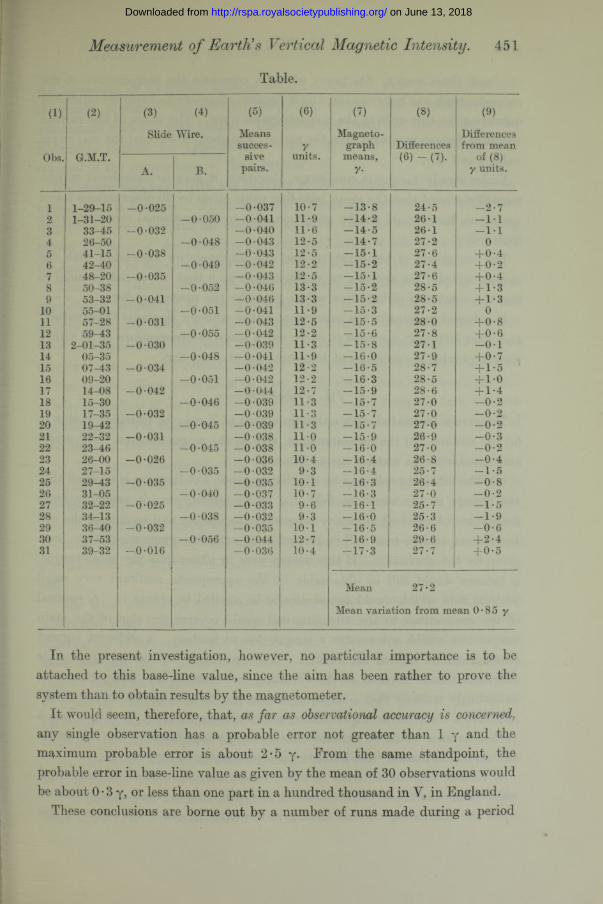
The final results deduced were the differences between the mean value of the differences of all the comparison readings and the individual difference readings. The mean variation from the mean given at the bottom of the last column is a measure of the probable amount by which any observation is different from the mean of a number of such observations. This latter figure is therefore a rough measure of the probable inaccuracy associated with the process of observation. I t must not be confused, of course, with inaccuracies in the absolute measurement of the whole vertical field associated with constant errors in the current ' measurement and in the constants and the set-up of the magnetometer. The results of a typical series of observations just as taken are given in the Table following.
Columns (1) and (2) give respectively the number and instant of the observation.
Colunns (3) and (4) give the slide-wire readings for the A and B positions alternatively taken from an arbitrary zero position near the centre of its scale.
Column (5) gives the means between the successive pairs, and column (6) gives the corresponding values in y units.
Column (7) gives the deduced mean values of y differences, from an arbitrary base line, as read off from the magnetograph record.
Column (8) gives the differences between corresponding readings in columns (6) and (7) in y units.
Column (9) gives the differences between the mean of all the values in column (8) and each individual reading. The mean value of the differences shown in column (9) is 0-85 y, and the maximum positive and negative values are 2*4 y and 2-7 y respectively.
The values of the various items by which the base-line value is calculated corresponding to the zero on the slide were
= 1 • 00036 int. ohm.R 2 + leads = 5*5071 int. ohm. x = 0*37 ohm.S -j- Sj = 1 *76 ohm.
Voltage of standard cell at 15° C. = 1*01842 int. volt.Helmholtz coil constant at 16° C. = 3*59598.Calculated base-line value V0 = 43152 y units.
on June 13, 2018http://rspa.royalsocietypublishing.org/Downloaded from
Measurement of Earth's Vertical Magnetic Intensity. 451
Table.
(1) (2) (3) (4) (5) (0) (7) (8) (9)Slide Wire. Means Magnet o- Differences
succes- y graph Differences from meanObs. G.M.T. sire units. means, (6) - (7). of (8)
A. B. pairs. y- y units.
i 1-29-15 -0-025 -0-037 10-7 -13-8 24-5 -2-72 1-31-20 -0-050 -0-041 11-9 -14-2 26-1 - 1 13 33-45 -0-032 -0-040 11-6 -14-5 26-1 - 1 14 26-50 -0-048 - 0 043 12-5 -14-7 27-2 05 41-15 -0-038 -0-043 12-5 -15-1 27-6 +0-46 42-40 -0-049 -0-042 12-2 -15-2 27-4 +0-27 48-20 - 0 035 -0-043 12-5 -1 5 1 27-6 +0-48 50-38 -0-052 -0-046 13-3 -15-2 28-5 + 1-39 53-32 -0-041 - 0 046 13-3 -15-2 28-5 + 1-3
10 55-01 -0-051 - 0 041 11-9 -15-3 27-2 011 57-28 -0-031 -0-043 12-5 -15-5 28-0 +0 - 812 59-43 -0-055 -0-042 12-2 -15-6 27-8 +0-613 2-01-35 -0-030 -0-039 11-3 -15-8 27-1 -0-114 05-35 -0-048 -0-041 11-9 -16-0 27-9 +0-715 07-43 -0-034 -0-042 12-2 -16-5 28-7 + 1-516 09-20 -0-051 -0-042 12-2 -16-3 28-5 + 1-017 14-08 -0-042 -0-044 12-7 -15-9 28-6 + 1-418 15-30 -0-046 -0-039 11-3 -15-7 27-0 -0-219 17-35 -0-032 -0-039 11-3 — 15-7 27-0 -0-220 19-42 - 0 045 -0-039 11-3 -15-7 27-0 -0-221 22-32 -0-031 -0-038 11-0 -15-9 26-9 -0-322 23-46 -0-045 -0-038 11-0 -16-0 27-0 -0-223 26-00 -0-026 -0-036 10-4 -16-4 26-8 -0-424 27-15 -0-035 - 0 032 9-3 -16-4 25-7 -1-525 29-43 -0-035 -0-035 10-1 -16-3 26-4 -0-826 31-05 - 0 040 -0-037 10-7 -16-3 27-0 -0-227 32-22 -0-025 -0-033 9-6 -16-1 25-7 -1-528 34-13 -0-038 -0-032 9-3 -16-0 25-3 -1-929 36-40 -0-032 -0-035 10-1 -16-5 26-6 -0-630 37-53 -0-056 -0-044 12-7 -16-9 29-6 + 2-431 39-32 -0-016 -0-036 10-4 -17-3 27-7 +0-5
Mean 27-2
Mean variation from mean 0*85 y
In the present investigation, however, no particular importance is to be attached to this base-line value, since the aim has been rather to prove the system than to obtain results by the magnetometer.
It would seem, therefore, that, as far as observational accuracy is ,any single observation has a probable error not greater than 1 y and the maximum probable error is about 2-5 y. From the same standpoint, the probable error in base-line value as given by the mean of 30 observations would be about 0 • 3 y, or less than one part in a hundred thousand in V, in England.
These conclusions are borne out by a number of runs made during a period
on June 13, 2018http://rspa.royalsocietypublishing.org/Downloaded from
452 D. W. Dye.J
of about three weeks. On many of these occasions the temperature of the magnetograph was not constant , and it became necessary to apply an estimated correction for this drift in the magnetograph trace. The mean of the various values of “ mean variation from the mean ” was about 0-8 y, and the maximum value was 1 • 2 y.
Under steady magnetic conditions, therefore, it may be considered experimentally proved that the mean base-line value given by 30 observations taken during an hour would not be uncertain, due to observational errors, by more than 0 • 3 y.
The variations of temperature, and the uncertainties associated with the magnetograph from one day to another, were such that it was not possible to test the constancy of base-line values given by the magnetometer.
I t is hoped to transfer the instrument to the Abinger Magnetic Observatory, and after setting it up there to carry out a series of observations of Y with a view to proving the accuracy of determination of a base line.
V II. Probable Errors.The errors associated with a determination of Y may be classified as due to
(a) the method, (b) the measurements, and (c) the magnetometer. The errors associated with the method are as follows :—
{a) The vibrating coil may be slightly magnetic but its mass is so small that the change in the resultant field due to hysteresis, etc., is probably quite negligible. A residual vibratory torque due to heating and cooling of the coil and its suspensions may still be present even with the symmetrical wave form given by the alternator. If this torque were in phase with the main torque, a balance would still be obtainable by the appropriate resultant very small vertical field which would automatically be applied to obtain it. A reversal of the connections to the vibrating coil would reverse the sign of the main torque but would not reverse a torque due to heating. A different current would then be needed for balance. An experiment showed no measurable difference due to reversal of the vibrating coil connections. It is, moreover, exceedingly unlikely that a vibrating torque due to heating and cooling would not have a component in quadrature with the main torque. In such a case a perfect balance would be unobtainable by simple adjustment of the Helmholtz coil current. Actually the balance when obtained was very sharp.
A further experiment tried in order to see the effect of an asymmetrical wave form was tried. This consisted in superposing a small steady current upon the alternating current flowing in the detector coil. The effect of this
on June 13, 2018http://rspa.royalsocietypublishing.org/Downloaded from
Measurement o f Earth’s Vertical Magnetic Intensity. 453
was apparent, as no perfect balance could be obtained, thus proving that the thermally produced fundamental frequency torque had a component in quadrature with the main torque. The effect was small and the setting of the Helmholtz current for approximate balance appeared to be unaffected by reversal of the connections on the vibrating coil.
The errors associated with the location of the vibrating coil have been discussed, and it has been shown that such errors are proportional to H and therefore increase towards the magnetic equator. By the method of observing in two positions of the vibrating coil axis 180° apart, it has been shown that the error may be reduced to less than 1 y when H = 0-5 C.G.S. unit.
There is a possible source of small error in the inevitable lack of perfect geometrical symmetry of the vibrating coil. If the suspensions are not strictly coincident with the axis of vibration, a small torque will result, since they are considerably displaced from the centre of the Helmholtz coil and are therefore not in a zero vertical magnetic field when this condition is obtained at the centre. Such error must be very small, since there are about 400 cm. of wire in the coil at an effective radius of about 3 mm. from the axis, whereas the suspension will almost certainly be within 0 • 3 mm. of the effective axis of vibration and has an effective length of about 3 cm. only.
(6) The errors associated with the measurements are those due to inaccuracy of observation and uncertainty in measurement of the current in the Helmholtz coil. The sensitivity is such that variations in setting the current may amount to the equivalent of 2-5 y in a single observation, with a probable variation of 1 y. The mean of a series of 20 observations would have a probable error of less than 0 • 5 y, due to limitation of sensitivity on the vibration coil.
The error associated with observing the current will include a small drift which may occur between the instant of the magnetometer observation and the observation of current on the potentiometer. This error is likely to be less than one part in a hundred thousand. The error in the finally deduced current might be as great as 1 part in 105, but the possible error in the unit in which the current is measured is 2 or 3 parts in 105, whether this unit is derived from standard resistances and a standard cell, or, as at the laboratory, from an absolute unit given by the current balance.
(c) The errors associated with the magnetometer are those due to errors in setting up and errors in its constant.
The former error has been discussed and was seen to be probably not greater than H/IO ’V, or in y units H/105.
on June 13, 2018http://rspa.royalsocietypublishing.org/Downloaded from
454 D. W. Dye. .
The error associated with the dimensions of the coil can only be estimated by a repetition of the measurements of length and diameter. Previous experience has shown that slow changes in the dimensions of marble cylinders do occur in the course of a few years, and they may in the present case amount to a few parts in a hundred thousand.
From these considerations it would appear that the complete magnetometer and its accessories form a means of obtaining a base-line value for vertical intensity which would be consistent to 1 or 2 y, but that the absolute value of the field in C.G.S. units is subject to an uncertainty of about twice this amount.
In conclusion, my thanks are due to the Metrology Department for the design and construction of parts of the mounting, to Mr. P. Yigoureux for much careful assistance in the observations and in the method of presenting the matter in Appendix I. My thanks are also due to the Director and to Dr. Chree for kindly interest in the development of the magnetometer.
Appendix I.
General case in which a Helmholtz coil system is set up with its axis nearly vertical and can be oriented about another axis nearly vertical. This latter is an axis of reference.
The detecting coil is set up with its plane nearly vertical and its axis of vibration pointing in any direction in a nearly horizontal plane, and capable of orientation about the axis of reference.
Let OX, OY and OZ be three axes of reference such that OY is coincident with the nearly vertical axis around which the Helmholtz coil and the vibrating coil can be oriented.
Let UM be the field produced by the Helmholtz coil and let its direction cosines be £, vj and £, where \ and £ are nearly zero and yj nearly unity.
Let the direction cosines of the vertical be X, [x and v, where X and v are nearly zero and ;x is nearly unity.
Let the earth’s field be F and its direction cosines be l, m and n. None of these is necessarily small.
Let the direction cosines of a line in the plane of the vibrating coil and perpendicular to its axis of vibration be a, (3 and y, where a and y are small and (3 is nearly unity.
The angle between F and the line a, [3, y is cos-1 (a£ + fit] + yO-The vibratory torque due to F is proportional to
F (cd + (3m + y
on June 13, 2018http://rspa.royalsocietypublishing.org/Downloaded from
Measurement o f Earth!sVertical Magnetic Intensity. 455
Again, the angle between Vm and the line a, [3, y iscos-1 (a£ + [3t] + y£)
and the vibratory torque is proportional to
UmK + ^ + yO-By adjustment of UM to the value Umi we can reduce the vibratory torque to
zero, so thatF (cd + (3m + Tn) = UMi (a£ + (3tj + y£). (1)
Now let the Helmholtz coil and the vibrating coil be oriented about the nearly vertical axis of reference OY through an angle 7t.
The new direction cosines becomey*
— TJV
l m n—a P —T
By adjustment of IJM to the value UM2, such that the vibratory torque is again zero, we have
F (— 7.1 + (3m — y n) = UM2 (oc£ + (3t] + TO* (2)
The mean of (1) and (2) givesF (3m = | (UM1 -f- UM2) (a£ + [3t] + yO*
The vertical component of the earth’s field = V is given byY = F (Xl + fxm + vn).
Eliminating F from (3) and (4) gives
2V 1 ( XZ+f xm+ v n ) (a £ +( 3T] +Y Q
(3)
(4)
Neglecting products of small quantities this gives
£(UM1 + UM2) = V . U l - ^ -[XT] \ [xmvn[xm (5)
In practice the plane and the axis of vibration of the vibrating coil are adjusted so that a and y are small by the process whereby Umi is made nearly equal to Um2- Also, the Helmholtz coil is adjusted so that \ and £ are very small.
We may therefore safely neglect the last two terms in equation (5). The simplified expression for V becomes
[XT]Umi+ Um2 1 — X? vn
[xm ( 6>2
on June 13, 2018http://rspa.royalsocietypublishing.org/Downloaded from
456 D. W. Dye.
The angles cos-1 X and cos-1 '/] can most certainly be adjusted to values smaller than 0 • 0001 radian. The values of p, and yj will therefore differ from unity by a quite negligible amount.
The correction which has to be applied to the mean of the two U readings reduces to the simple term — (XI -f- vn) in relation to unity.
I t is thus seen that the only quantity finally involved in these correctionsarising from the adjustments of the magnetometer is the departure from vertically of the axis about which the Helmholtz coil and the vibrating coil are oriented.
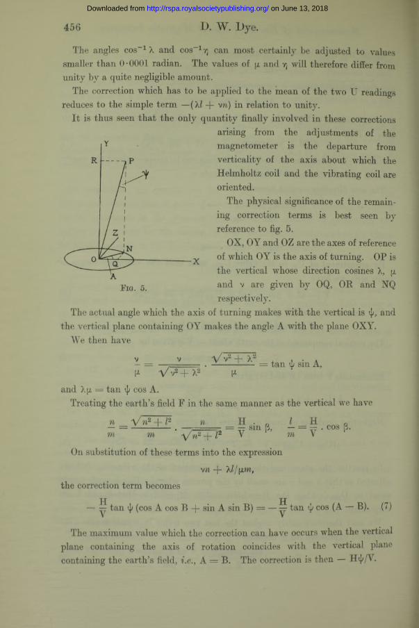
The physical significance of the remaining correction terms is best seen by reference to fig. 5.
OX, OY and OZ are the axes of reference of which OY is the axis of turning. OP is the vertical whose direction cosines X, jx and v are given by OQ, OR and NQ respectively.
The actual angle which the axis of turning makes with the vertical is <jq and the vertical plane containing OY makes the angle A with the plane OXY.
We then have
Fig. 5.
v V + X" = tan tj; sin A,ft V V2 + X̂ ^
and Xu = tan <]/ cos A.Treating the earth’s field F in the same manner as the vertical we have
n _a/ m2 + l2mm m
n H . „ H n. t--...= — sin B, — = • cos p.A /n 2+ l 2 V
On substitution of these terms into the expression
vn - f - X I J [ i m ,
the correction term becomes
— ^ tan ^ (cos A cos B + sin A sin B) = — S tan <]/ cos (A — B). (7)
The maximum value which the correction can have occurs when the vertical plane containing the axis of rotation coincides with the vertical plane containing the earth’s field, i.e., A = B. The correction is then — H<j//V.
on June 13, 2018http://rspa.royalsocietypublishing.org/Downloaded from
Measurement o f Earth's Vertical Magnetic Intensity. 457
Expressed as an error in relation to unity, it is seen that the error may be large in regions near the magnetic equator, but expressed in terms of y units the error is simply H + For a maximum value of H equal to 0*5 C.G.S. unit, it is seen that ^ should be reduced to 2 X 10-0 radian for an accuracy of 1 y to be obtained.
With the present instrument such an angle of departure of the axis of turning from the vertical can just be detected.
Appendix II.
Measurement of the Current.
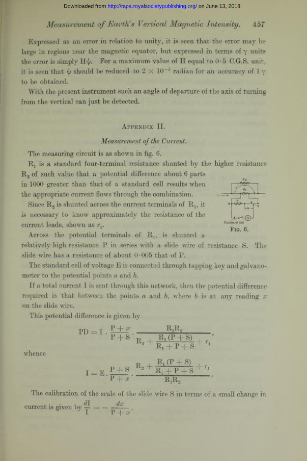
The measuring circuit is as shown in fig. 6.Rx is a standard four-terminal resistance shunted by the higher resistance
R 2 of such value that a potential difference about 6 parts in 1000 greater than that of a standard cell results when the appropriate current flows through the combination. i r ^ v- i - t — tVywq—i-4 -
Since R0 is shunted across the current terminals of R., it a - AVvVA' * —-r-—*Lx— '*
Sttuidard Cell
Fig. 6.
is necessary to know approximately the resistance of the current leads, shown as rv
Across the potential terminals of R ,, is shunted a relatively high resistance P in series with a slide wire of resistance S. The slide wire has a resistance of about 0 • 005 that of P.
The standard cell of voltage E is connected through tapping key and galvanometer to the potential points a and h.
If a total current I is sent through this network, then the potential difference required is that between the points a and b, where b is at any reading x on the slide wire.
This potential difference is given by
P + x____R^Rg__PI) = I
whence
P + S* , R, (P + S)2 1 Rx + P + S
I == E . P + S P + x
Ri (P + S) Ri + P + S ri
RjR.i
The calibration of the scale of the slide wire S in terms of a small change in
current is given by — — ----- —— .I P + x
on June 13, 2018http://rspa.royalsocietypublishing.org/Downloaded from
458 Measurement o f Earth's Vertical Magnetic Intensity.
In the case of the Helmholtz coil described, and for the value of Y in England, the value of I is about 1 • 19 amperes.
It is convenient to use a slide wire of 1 ohm resistance and to choose a value of P such that the slide wire covers a range of about 5 parts in 1000 in V. Under these conditions P becomes 200 ohms.
If = 1 ohm and R 2 = 6 ohms, then the effect of the current leads of Rx is small, but not quite negligible, if they have a resistance of 0• 0001 ohm.
For a base line corresponding to a value of x equal to 0 • 5 ohm the value of I becomes
r l 201201 0 ‘ 9091-01830 X — ■ X ------- amperes
200-5 6
= 1-19017.
For a change of slide wire reading of 0 • 001 ohm the proportionate change of current necessary to give balance is equal to
55Tb = 5 parts 1,110C'It is thus seen that accuracy to one part in a hundred thousand can be
obtained and observed if Rx and E are known to this accuracy.A more open scale can be obtained on the slide wire at the expense of a smaller
range, by choosing a higher value of P. By introducing the constant of the Helmholtz coil into the calculations, it is easy to calibrate the scale of S to read change of V directly in y units.
on June 13, 2018http://rspa.royalsocietypublishing.org/Downloaded from