a lower-limb exoskeleton for gait assistance in quadriplegia · a lower-limb exoskeleton for gait...
TRANSCRIPT
A lower-limb exoskeleton for gait assistance in quadriplegia
Daniel Sanz-Merodio, Manuel Cestari, Juan Carlos Arevalo and Elena GarciaCentre for Automation and Robotics, CSIC
La Poveda, 28500 Madrid, SpainPhone. +34-918711900 FAX. +34-918717050
Email: [email protected] author: D. Sanz-Merodio
Research Article
Abstract— The potential of lower-limb exoskeletonsand powered orthoses in gait assistance applications forpatients with locomotive disorders would have a terrificimpact in the society of the near future. This paperpresents the development and main features of a lowerlimb exoskeleton being developed as an active orthosis toallow a quadriplegic child to walk. As the patient is notable to move any of her limbs, the device will produceher basic motions in everyday-life activities: stand up,sit down, and walk stably. Synergic biarticular actuationin the ankle, compliance controller based on the forcemeasured by insoles at the feet and the definition ofparameterized hip and foot trajectories that allow tochoose the characteristics of gait are some of the newfeatures included in this prototype. Experiments validatethe improved performance of gait based on the proposedapproach.
I. INTRODUCTION
Exoskeletons and active orthosis for human lowerlimbs are robotic devices worn by an operator thatfit closely and operate in parallel with the humanlegs, and are the best choice for augmenting humanperformance in real environments. This is an area ofservice robotics with a significant relevance in the nearfuture society with applications ranging from industrialand military purposes to assistive technologies forphysically challenged persons. In general, the termexoskeleton is used to describe a device that augmentsthe performance of an able-bodied wearer, while theterm active orthosis is typically used to describe adevice that is used to increase the locomotive ability ofa person suffering from a leg pathology [1]. Althoughresearch in robotic exoskeletons and active orthosesbegan in the early 1960s, the technology required tobuild functional prototypes started to arise just onedecade ago.
Today there are commercially available autonomouslower-limb exoskeletons mainly devised for militaryapplications. However, the development of fully func-tional active orthosis for paralyzed patients still re-quires further research, featuring limited functionalitywith the aid of crutches. Specifically, the developmentof active orthosis for completely paralyzed patients,such as quadriplegic, has not been considered becauseof the added difficulty of stability control and user’sintention acquisition.
This paper presents the development of a full lower-limb active orthosis for helping out a 8-year oldquadriplegic girl for walking. The exoskeleton hasbeen designed to be portable, lightweight, comfortableand safe to the user while providing stability andlocomotion. The patient is affected by quadriplegia,which does not allow the user to interact with the robotfor its tele-operation. Therefore, the main benefits of aexoskeleton which rely on the perfect combination ofrobot strength and user motion ability are here lost, andthe complete motion of the robotic orthosis, includingthe control of stability has to be programmed. Theproposed approach is different from those presented incurrent development exoskeletons for disable people.A concept of full lower-limb active orthosis whichlocomotion cycle is based on a new parametrizedtrajectory generation has been developed. However, inorder for the robot to be robust from perturbationsin the sagittal plane and for the control of dynamicstability, an impedance control approach has beenproposed. The first prototype here presented includesa passive synergic actuation in the ankle and walksat moderate speeds (below 1 m/s) in straight line.In this paper, Section II presents a brief backgroundon lower-limb exoskeletons, Section III describes thefull active orthosis concept, Sections IV to V developon hardware specifications for the robotic structure,actuators and sensorial system. Section VI details thecontrol of locomotion. Section VII shows the safe gaitpattern followed by the joints. Finally Section VIIIpresents the main conclusions.
II. BACKGROUND IN LOWER-LIMB EXOSKELETONS
The concept of an exoskeleton or an active orthosisis an integrated system composed of the strength ofthe robot and the intelligence of the human wearer. Insuch an ideal human-machine integration the researchconcentrates in achieving means to acquire the user’sintention and in user-safe control algorithms to makethe robot follow the user’s intention quickly and with-out delay. In this line of attention, relevant work hasbeen developed [2]–[4], making emphasis on the load-carrying capacity through the development of powerfulactuators for force augmentation.
978-1-4673-2126-6/12/$31.00 © 2012 IEEE
Portable assistive exoskeletons for both performanceaugmenting and rehabilitative purposes have been de-veloped, making emphasis on the capture of the user’sintention through biological signal sensing [5], [6]and limb-force sensing [7]. Conversely, the work onactive orthoses has not progressed past the stage ofpreliminary investigations, probably due to a morelimited funding. Active orthosis are exoskeletons de-signed to allow a person with leg-pathology to walk.Such leg-pathology can be as severe as a paralysis.The majority of the orthotic devices already devel-oped are not energetically autonomous, typically beingtethered to some external power supply, and usedinside hospitals for rehabilitative purposes [8]–[10].Such rehabilitation exoskeletons work in place or intreadmill for gait training, so they are not meant to beportable and do not feature the challenges of portabledevices. The challenges associated with developingfunctional, autonomous exoskeletons are [1]: portableand long-lasting power supplies, lightweight, powerfulactuators, and efficient transmissions.
The issue of portability is one of the major factorsthat limit the application of active orthoses outsideof clinical therapy. The development of portable ac-tive lower-limb orthosis would have a terrific impactin our near future. The assistance of disabled andelderly people is predicted to be one of the mostimportant service applications of robotic systems [11].The development of autonomous, portable lower-limbactive orthosis will contribute to providing physicallychallenged persons with: (1) Improved quality of life,making their daily life much more “normal” than ever;(2) Autonomy and endurance to move around; (3)Details which are relevant for the disabled: normalheight at standing up posture, allowing the person totalk with people at their same height, and to reachswitches and objects which were placed at the heightof an upright person.
Early lower-limb orthosis for the paraplegic wereexternally powered and limited to predefined mo-tions [12]. Today there are commercially availableautonomous lower-limb orthotic devices for paraplegicpatients, developed by Argo Medical Technologies ofIsrael (ReWalk), Rex Bionics (REX) and BerkeleyBionics (e-Legs), being this last one the only activeorthosis with moderately adequate autonomy (6 hours),lightweight structure and natural user-intention moni-toring system. Some research devices like VanderbiltOrthosis [13] and Mina [14] only provide one hourof autonomy.A completely different concept was pro-posed at the MIT where a quasi-passive exoskeletonwas developed with focus on energy efficiency [15].However, the development of active orthosis for com-pletely paralyzed patients, such as quadriplegic, hasnot been considered because of the added difficulty ofstability control and user’s intention acquisition.
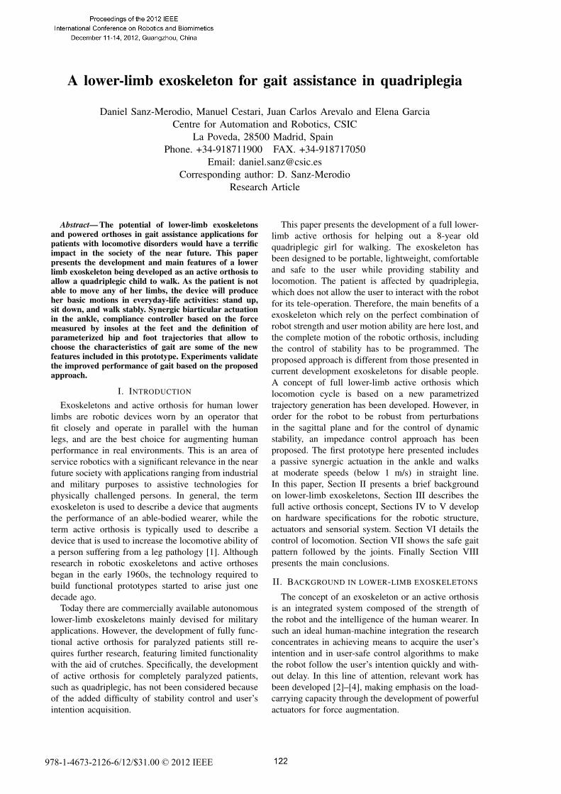
Fig. 1. Concept of the ATLAS exoskeleton showing main compo-nents
III. ATLAS CONCEPT
The ATLAS exoskeleton falls within the classi-fication of active orthosis as it is devised for gaitassistance, not for load-carrying augmentation [1].In orthotic terminology it can be considered as anactive THKAFO (Trunk-Hip-Knee-Ankle-Foot Ortho-sis). ATLAS is intended to support a 25-kg girl andhelp her out with walking at a moderate speed (≤1m/s). The particular pathology of ATLAS’ user isquadriplegia: she is a 8 year-old girl affected byparalysis of both legs and arms (the girl can onlymove her left hand). This paralysis was caused byspinal cord injury, and therefore, she cannot move herextremities, and she cannot control the torso to keepbalance. Besides, biological signals from the motorcortex do not reach the extremities in quadriplegicpatients.
With all this in mind, the ATLAS exoskeleton hasbeen thought of as a lightweight, easy to handle andto put on robotic system composed of the followingmain components, sketched in Figure 1:
1) Mechanical structure: As a lower limb orthosis,it must be simple, lightweight, strong, durableand cosmetically acceptable. It is a 6 DOFmechanism, having 3 DOF per leg: hip, knee andankle to allow the user to move in the sagittalplane. The structure is attached to the user bodythrough comfortable belts. The exoskeleton willbe worn by the user underneath her cloths, so itmust not be bulky.
2) Actuation system: The flexion and extensionmotion of the hip and knee joints is drivenby electrical brushless Maxon motors in com-bination with harmonic drive units. The setupprovides repeated peak torque up to 57 Nm, andaverage torque of 32 Nm at speed higher than20 rpm for each actuated joint. The result is amotor-gearbox kit that provides large power-to-weight ratio while keeping flat enough for notto bother the user motion. At the ankle, a steel
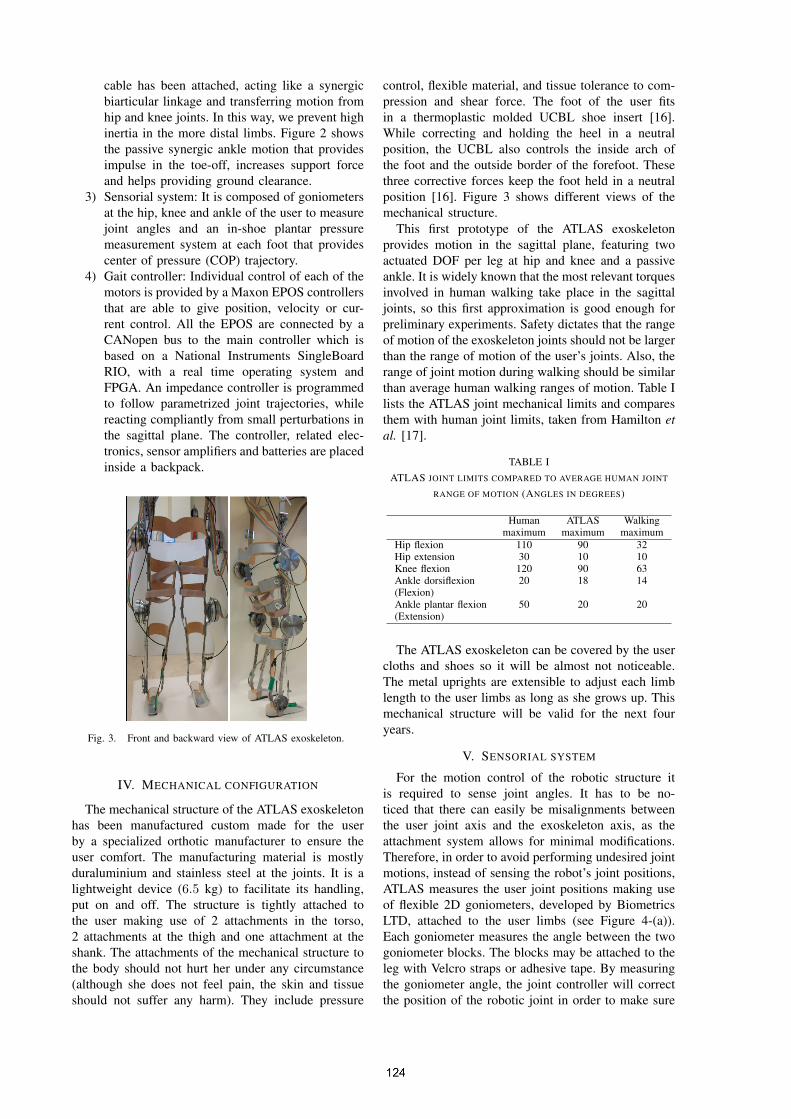
cable has been attached, acting like a synergicbiarticular linkage and transferring motion fromhip and knee joints. In this way, we prevent highinertia in the more distal limbs. Figure 2 showsthe passive synergic ankle motion that providesimpulse in the toe-off, increases support forceand helps providing ground clearance.
3) Sensorial system: It is composed of goniometersat the hip, knee and ankle of the user to measurejoint angles and an in-shoe plantar pressuremeasurement system at each foot that providescenter of pressure (COP) trajectory.
4) Gait controller: Individual control of each of themotors is provided by a Maxon EPOS controllersthat are able to give position, velocity or cur-rent control. All the EPOS are connected by aCANopen bus to the main controller which isbased on a National Instruments SingleBoardRIO, with a real time operating system andFPGA. An impedance controller is programmedto follow parametrized joint trajectories, whilereacting compliantly from small perturbations inthe sagittal plane. The controller, related elec-tronics, sensor amplifiers and batteries are placedinside a backpack.
Fig. 3. Front and backward view of ATLAS exoskeleton.
IV. MECHANICAL CONFIGURATION
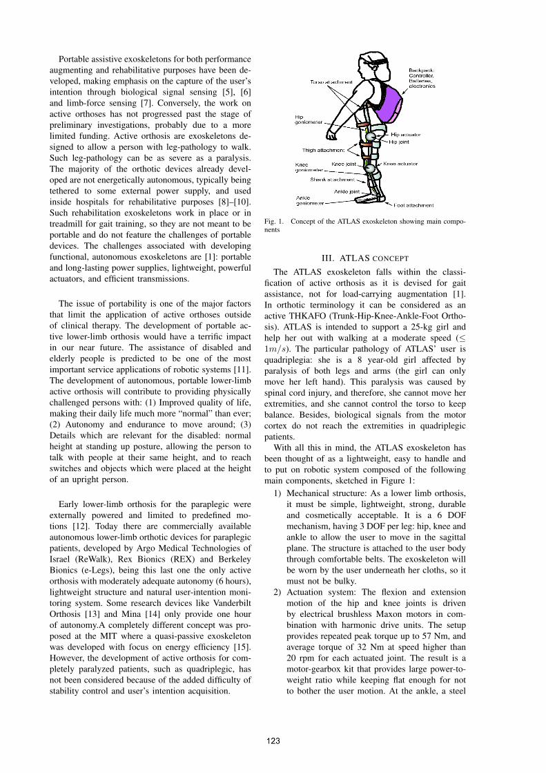
The mechanical structure of the ATLAS exoskeletonhas been manufactured custom made for the userby a specialized orthotic manufacturer to ensure theuser comfort. The manufacturing material is mostlyduraluminium and stainless steel at the joints. It is alightweight device (6.5 kg) to facilitate its handling,put on and off. The structure is tightly attached tothe user making use of 2 attachments in the torso,2 attachments at the thigh and one attachment at theshank. The attachments of the mechanical structure tothe body should not hurt her under any circumstance(although she does not feel pain, the skin and tissueshould not suffer any harm). They include pressure
control, flexible material, and tissue tolerance to com-pression and shear force. The foot of the user fitsin a thermoplastic molded UCBL shoe insert [16].While correcting and holding the heel in a neutralposition, the UCBL also controls the inside arch ofthe foot and the outside border of the forefoot. Thesethree corrective forces keep the foot held in a neutralposition [16]. Figure 3 shows different views of themechanical structure.
This first prototype of the ATLAS exoskeletonprovides motion in the sagittal plane, featuring twoactuated DOF per leg at hip and knee and a passiveankle. It is widely known that the most relevant torquesinvolved in human walking take place in the sagittaljoints, so this first approximation is good enough forpreliminary experiments. Safety dictates that the rangeof motion of the exoskeleton joints should not be largerthan the range of motion of the user’s joints. Also, therange of joint motion during walking should be similarthan average human walking ranges of motion. Table Ilists the ATLAS joint mechanical limits and comparesthem with human joint limits, taken from Hamilton etal. [17].
TABLE IATLAS JOINT LIMITS COMPARED TO AVERAGE HUMAN JOINT
RANGE OF MOTION (ANGLES IN DEGREES)
Human ATLAS Walkingmaximum maximum maximum
Hip flexion 110 90 32Hip extension 30 10 10Knee flexion 120 90 63Ankle dorsiflexion 20 18 14(Flexion)Ankle plantar flexion 50 20 20(Extension)
The ATLAS exoskeleton can be covered by the usercloths and shoes so it will be almost not noticeable.The metal uprights are extensible to adjust each limblength to the user limbs as long as she grows up. Thismechanical structure will be valid for the next fouryears.
V. SENSORIAL SYSTEM
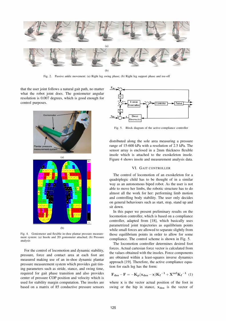
For the motion control of the robotic structure itis required to sense joint angles. It has to be no-ticed that there can easily be misalignments betweenthe user joint axis and the exoskeleton axis, as theattachment system allows for minimal modifications.Therefore, in order to avoid performing undesired jointmotions, instead of sensing the robot’s joint positions,ATLAS measures the user joint positions making useof flexible 2D goniometers, developed by BiometricsLTD, attached to the user limbs (see Figure 4-(a)).Each goniometer measures the angle between the twogoniometer blocks. The blocks may be attached to theleg with Velcro straps or adhesive tape. By measuringthe goniometer angle, the joint controller will correctthe position of the robotic joint in order to make sure
(a)
(b)
Fig. 2. Passive ankle movement: (a) Right leg swing phase; (b) Right leg support phase and toe-off
that the user joint follows a natural gait path, no matterwhat the robot joint does. The goniometer angularresolution is 0.007 degrees, which is good enough forcontrol purposes.
(a)
(b)
Fig. 4. Goniometer and flexible in-shoe plantar pressure measure-ment system: (a) Insole and 2D goniometer attached; (b) Pressureanalysis
For the control of locomotion and dynamic stability,pressure, force and contact area at each foot aremeasured making use of an in-shoe dynamic plantarpressure measurement system which provides gait tim-ing parameters such as stride, stance, and swing time,required for gait phase transition and also providescenter of pressure COP position and velocity which isused for stability margin computation. The insoles arebased on a matrix of 85 conductive pressure sensors
Fig. 5. Block diagram of the active-compliance controller
distributed along the sole area measuring a pressurerange of 15-600 kPa with a resolution of 2.5 kPa. Thesensor array is enclosed in a 2mm thickness flexibleinsole which is attached to the exoskeleton insole.Figure 4 shows insole and measurement analysis data.
VI. GAIT CONTROLLER
The control of locomotion of an exoskeleton for aquadriplegic child has to be thought of in a similarway as an autonomous biped robot. As the user is notable to move her limbs, the robotic structure has to doalmost all the work for her: performing limb motionand controlling body stability. The user only decideson general behaviours such as start, stop, stand up andsit down.
In this paper we present preliminary results on thelocomotion controller, which is based on a compliancecontroller, adapted from [18], which basically usesparametrized joint trajectories as equilibrium pointswhile small forces are allowed to separate slightly fromthose equilibrium points in order to allow for somecompliance. The control scheme is shown in Fig. 5.
The locomotion controller determines desired footforces. Actual cartesian force vector is calculated fromthe values obtained with the insoles. Force componentsare obtained within a least-squares inverse dynamicsapproach [19]. Therefore, the active compliance equa-tion for each leg has the form:
Fdes−F = −Kp(xdes−x)Kf−1+XrefKf
−1 (1)
where x is the vector actual position of the foot inswing or the hip in stance, xdes is the vector of
−300 −200 −100 0 100 200 300 400−700
−600
−500
−400
−300
−200
−100
0
X (mm)
Z (
mm
)
Original CGA path reference
Modi!ed path by force feedback
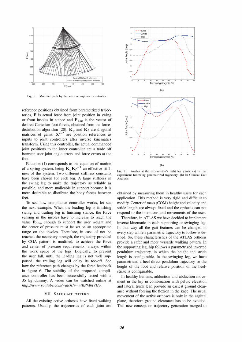
Fig. 6. Modified path by the active-compliance controller
reference positions obtained from parametrized trajec-tories, F is actual force from joint position in swingor from insoles in stance and Fdes is the vector ofdesired Cartesian foot forces, obtained from the force-distribution algorithm [20]. Kp and Kf are diagonalmatrices of gains. Xref are position references asinputs to joint controllers after inverse kinematicstransform. Using this controller, the actual commandedjoint positions to the inner controller are a trade offbetween user joint angle errors and force errors at thefoot.
Equation (1) corresponds to the equation of motionof a spring system, being KpKf
−1 an effective stiff-ness of the system. Two different stiffness constantshave been chosen for each leg. A large stiffness inthe swing leg to make the trajectory as reliable aspossible, and more malleable in support because it ismore desirable to distribute the body forces betweenfeet.
To see how compliance controller works, let seethe next example. When the leading leg is finishingswing and trailing leg is finishing stance, the forcesensing in the insoles have to increase to reach thevalue Fdes, enough to support the user weight andthe center of pressure must be set on an appropriaterange on the insoles. Therefore, in case of not bereached the necessary strength, the trajectory providedby CGA pattern is modified, to achieve the forceand center of pressure requirements; always withinthe work space of the legs. Logically, to preventthe user fall, until the leading leg is not well sup-ported, the trailing leg will delay its toe-off. Seehow the reference path changes by the force feedbackin figure 6. The stability of the proposed compli-ance controller has been successfully tested with a35 kg dummy. A video can be watched online athttp://www.youtube.com/watch?v=ntRPhI6tVHo.
VII. SAFE GAIT PATTERN
All the existing active orthoses have fixed walkingpatterns. Usually, the trajectories of each joint are
0 10 20 30 40 50 60 70 80 90 100
−70
−60
−50
−40
−30
−20
−10
0
10
20
Percent gait cycle (%)
Joint Angle (deg)
Knee
Ankle
Hip
(a)
0 10 20 30 40 50 60 70 80 90 100
−40
−30
−20
−10
0
Percent gait cycle (%)
Joint Angle (deg)
Knee
Ankle
Hip
(b)
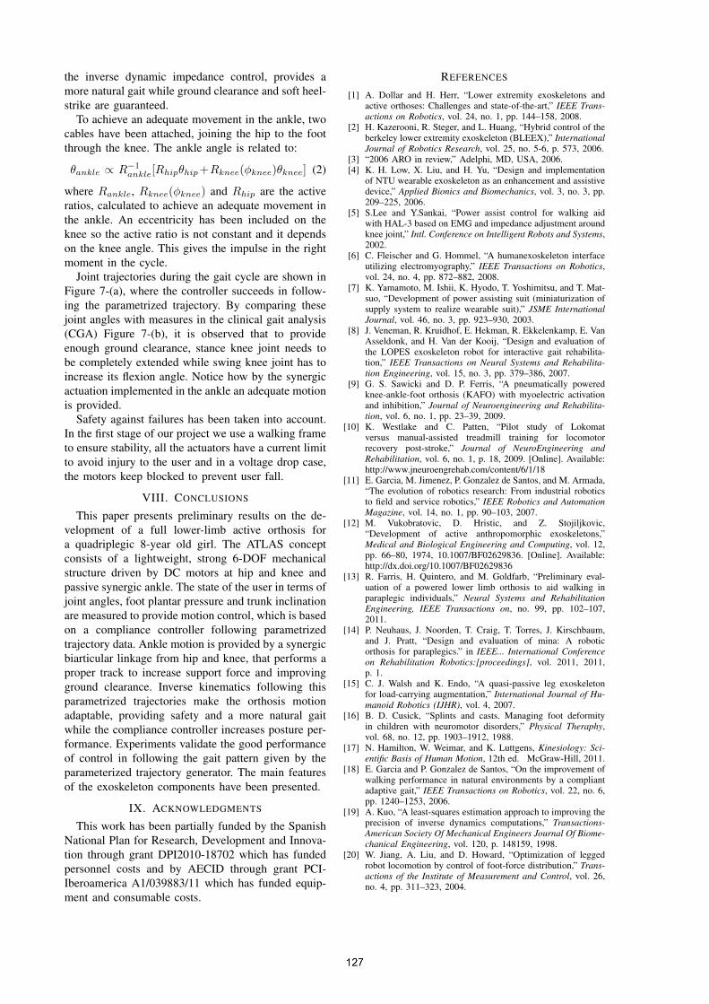
Fig. 7. Angles at the exoskeleton’s right leg joints: (a) In realexperiment following parametrized trajectory; (b) In Clinical GaitAnalysis
obtained by measuring them in healthy users for eachapplication. This method is very rigid and difficult tomodify. Center of mass (COM) height and velocity andstride length are always fixed and the orthosis can notrespond to the intentions and movements of the user.
Therefore, in ATLAS we have decided to implementinverse kinematic in each supporting or swinging leg.In that way all the gait features can be changed inevery step while a parametric trajectory to follow is de-fined. So, these characteristics of the ATLAS orthosisprovide a safer and more versatile walking pattern. Inthe supporting leg, hip follows a parametrized invertedpendulum trajectory, in which the height and stridelength is configurable. In the swinging leg, we haveparametrized a heel direct pendulum trajectory so theheight of the foot and relative position of the heel-strike is configurable.
In healthy humans, adduction and abduction move-ment in the hip in combination with pelvic elevationand lateral trunk lean provide an easiest ground clear-ance without forcing the flexion in the knee. The usualmovement of the active orthoses is only in the sagittalplane, therefore ground clearance has to be avoided.This new concept on trajectory generation merged to
the inverse dynamic impedance control, provides amore natural gait while ground clearance and soft heel-strike are guaranteed.
To achieve an adequate movement in the ankle, twocables have been attached, joining the hip to the footthrough the knee. The ankle angle is related to:
θankle ∝ R−1ankle[Rhipθhip+Rknee(ϕknee)θknee] (2)
where Rankle, Rknee(ϕknee) and Rhip are the activeratios, calculated to achieve an adequate movement inthe ankle. An eccentricity has been included on theknee so the active ratio is not constant and it dependson the knee angle. This gives the impulse in the rightmoment in the cycle.
Joint trajectories during the gait cycle are shown inFigure 7-(a), where the controller succeeds in follow-ing the parametrized trajectory. By comparing thesejoint angles with measures in the clinical gait analysis(CGA) Figure 7-(b), it is observed that to provideenough ground clearance, stance knee joint needs tobe completely extended while swing knee joint has toincrease its flexion angle. Notice how by the synergicactuation implemented in the ankle an adequate motionis provided.
Safety against failures has been taken into account.In the first stage of our project we use a walking frameto ensure stability, all the actuators have a current limitto avoid injury to the user and in a voltage drop case,the motors keep blocked to prevent user fall.
VIII. CONCLUSIONS
This paper presents preliminary results on the de-velopment of a full lower-limb active orthosis fora quadriplegic 8-year old girl. The ATLAS conceptconsists of a lightweight, strong 6-DOF mechanicalstructure driven by DC motors at hip and knee andpassive synergic ankle. The state of the user in terms ofjoint angles, foot plantar pressure and trunk inclinationare measured to provide motion control, which is basedon a compliance controller following parametrizedtrajectory data. Ankle motion is provided by a synergicbiarticular linkage from hip and knee, that performs aproper track to increase support force and improvingground clearance. Inverse kinematics following thisparametrized trajectories make the orthosis motionadaptable, providing safety and a more natural gaitwhile the compliance controller increases posture per-formance. Experiments validate the good performanceof control in following the gait pattern given by theparameterized trajectory generator. The main featuresof the exoskeleton components have been presented.
IX. ACKNOWLEDGMENTS
This work has been partially funded by the SpanishNational Plan for Research, Development and Innova-tion through grant DPI2010-18702 which has fundedpersonnel costs and by AECID through grant PCI-Iberoamerica A1/039883/11 which has funded equip-ment and consumable costs.
REFERENCES
[1] A. Dollar and H. Herr, “Lower extremity exoskeletons andactive orthoses: Challenges and state-of-the-art,” IEEE Trans-actions on Robotics, vol. 24, no. 1, pp. 144–158, 2008.
[2] H. Kazerooni, R. Steger, and L. Huang, “Hybrid control of theberkeley lower extremity exoskeleton (BLEEX),” InternationalJournal of Robotics Research, vol. 25, no. 5-6, p. 573, 2006.
[3] “2006 ARO in review,” Adelphi, MD, USA, 2006.[4] K. H. Low, X. Liu, and H. Yu, “Design and implementation
of NTU wearable exoskeleton as an enhancement and assistivedevice,” Applied Bionics and Biomechanics, vol. 3, no. 3, pp.209–225, 2006.
[5] S.Lee and Y.Sankai, “Power assist control for walking aidwith HAL-3 based on EMG and impedance adjustment aroundknee joint,” Intl. Conference on Intelligent Robots and Systems,2002.
[6] C. Fleischer and G. Hommel, “A humanexoskeleton interfaceutilizing electromyography,” IEEE Transactions on Robotics,vol. 24, no. 4, pp. 872–882, 2008.
[7] K. Yamamoto, M. Ishii, K. Hyodo, T. Yoshimitsu, and T. Mat-suo, “Development of power assisting suit (miniaturization ofsupply system to realize wearable suit),” JSME InternationalJournal, vol. 46, no. 3, pp. 923–930, 2003.
[8] J. Veneman, R. Kruidhof, E. Hekman, R. Ekkelenkamp, E. VanAsseldonk, and H. Van der Kooij, “Design and evaluation ofthe LOPES exoskeleton robot for interactive gait rehabilita-tion,” IEEE Transactions on Neural Systems and Rehabilita-tion Engineering, vol. 15, no. 3, pp. 379–386, 2007.
[9] G. S. Sawicki and D. P. Ferris, “A pneumatically poweredknee-ankle-foot orthosis (KAFO) with myoelectric activationand inhibition,” Journal of Neuroengineering and Rehabilita-tion, vol. 6, no. 1, pp. 23–39, 2009.
[10] K. Westlake and C. Patten, “Pilot study of Lokomatversus manual-assisted treadmill training for locomotorrecovery post-stroke,” Journal of NeuroEngineering andRehabilitation, vol. 6, no. 1, p. 18, 2009. [Online]. Available:http://www.jneuroengrehab.com/content/6/1/18
[11] E. Garcia, M. Jimenez, P. Gonzalez de Santos, and M. Armada,“The evolution of robotics research: From industrial roboticsto field and service robotics,” IEEE Robotics and AutomationMagazine, vol. 14, no. 1, pp. 90–103, 2007.
[12] M. Vukobratovic, D. Hristic, and Z. Stojiljkovic,“Development of active anthropomorphic exoskeletons,”Medical and Biological Engineering and Computing, vol. 12,pp. 66–80, 1974, 10.1007/BF02629836. [Online]. Available:http://dx.doi.org/10.1007/BF02629836
[13] R. Farris, H. Quintero, and M. Goldfarb, “Preliminary eval-uation of a powered lower limb orthosis to aid walking inparaplegic individuals,” Neural Systems and RehabilitationEngineering, IEEE Transactions on, no. 99, pp. 102–107,2011.
[14] P. Neuhaus, J. Noorden, T. Craig, T. Torres, J. Kirschbaum,and J. Pratt, “Design and evaluation of mina: A roboticorthosis for paraplegics.” in IEEE... International Conferenceon Rehabilitation Robotics:[proceedings], vol. 2011, 2011,p. 1.
[15] C. J. Walsh and K. Endo, “A quasi-passive leg exoskeletonfor load-carrying augmentation,” International Journal of Hu-manoid Robotics (IJHR), vol. 4, 2007.
[16] B. D. Cusick, “Splints and casts. Managing foot deformityin children with neuromotor disorders,” Physical Theraphy,vol. 68, no. 12, pp. 1903–1912, 1988.
[17] N. Hamilton, W. Weimar, and K. Luttgens, Kinesiology: Sci-entific Basis of Human Motion, 12th ed. McGraw-Hill, 2011.
[18] E. Garcia and P. Gonzalez de Santos, “On the improvement ofwalking performance in natural environments by a compliantadaptive gait,” IEEE Transactions on Robotics, vol. 22, no. 6,pp. 1240–1253, 2006.
[19] A. Kuo, “A least-squares estimation approach to improving theprecision of inverse dynamics computations,” Transactions-American Society Of Mechanical Engineers Journal Of Biome-chanical Engineering, vol. 120, p. 148159, 1998.
[20] W. Jiang, A. Liu, and D. Howard, “Optimization of leggedrobot locomotion by control of foot-force distribution,” Trans-actions of the Institute of Measurement and Control, vol. 26,no. 4, pp. 311–323, 2004.