a low-viscousity, highly thermally conductive epoxy molding … · 2004-03-02 · a low-viscousity,...
TRANSCRIPT
*e-mail: [email protected]/02/78-07©2004 Polymer Society of Korea
78
Macromolecular Research, Vol. 12, No. 1, pp 78-84 (2004)
A Low-Viscousity, Highly Thermally Conductive Epoxy Molding Compound (EMC)
Jong-Woo Bae
Korea Institute of Footwear and Leather Technology, Busan 614-100, Korea
Wonho Kim*, Seungchul Hwang, and Young-Sun Choe
Department of Chemical Engineering, Pusan National University, Busan 609-735, Korea
Sang-Hyun Lee
Division of Quantum Metrology, Korea Research Institute of Standards and Science, Daejeon 305-600, Korea
Received Aug. 20, 2003; Revised Jan. 19, 2004
Abstract: Advanced epoxy molding compounds (EMCs) should be considered to alleviate the thermal stress problemscaused by low thermal conductivity and high elastic modulus of an EMC and by the mismatch of the coefficient ofthermal expansion (CTE) between an EMC and the Si-wafer. Though AlN has some advantages, such as high thermalconductivity and mechanical strength, an AlN-filled EMC could not be applied to commercial products because ofits low fluidity and high modulus. To solve this problem, we used 2-µm fused silica, which has low porosity andspherical shape, as a small size filler in the binary mixture of fillers. When the composition of the silica in the binaryfiller system reached 0.3, the fluidity of EMC was improved more than twofold and the mechanical strength wasimproved 1.5 times, relative to the 23-µm AlN-filled EMC. In addition, the values of the elastic modulus and thedielectric constant were reduced to 90%, although the thermal conductivity of EMC was reduced from 4.3 to 2.5 W/m-K,when compared with the 23-µm AlN-filled EMC. Thus, the AlN/silica (7/3)-filled EMC effectively meets therequirements of an advanced electronic packaging material for commercial products, such as high thermal conductivity(more than 2 W/m-K), high fluidity, low elastic modulus, low dielectric constant, and low CTE.
Keywords: low viscosity, high thermal conductivity, AlN, fused silica, EMC.
Introduction
Over the last few decades, the micro-electronic industry,which needs development in computer and communicationdevices for fast treatment of huge amounts of data hasgrown rapidly in size. Thus, high performance integratedcircuits are in demand and the demand has been increasingsteeply.1 The major functions of packaging are to protectdevices from mechanical and chemical hazards, to distributesignals and power, and to dissipate heat. The ability of apackage to adequately perform these functions depends onthe properties of the device as well as the properties of pack-age materials.
Recently, to improve performance and reduce cost, thedensity of package has been increased. With the increaseddensity of package, the electrical energy consumed in adevice ultimately appears as heat, elevating the temperature
of the active junction and other parts of the package housingof the device. Increased temperature adversely affects thereliability of the device.2 So, the package material should havehigh thermal diffusion rate, i.e., high thermal conductivity.There are several other physical properties of polymericmaterials that are important to micro-electronics packaging,some of which are a low viscosity, a low dielectric constant,a low coefficient of thermal expansion (CTE), a low elasticmodulus, a high water resistance, and a high flexuralstrength.3,4
However, typical epoxy molding compounds (EMC) suchas fused silica filled EMC, which have low thermal conduc-tivity, cannot effectively dissipate the heat of a silicon die.Therefore, advanced epoxy molding compounds should beconsidered to alleviate thermal stress problems caused bylow thermal conductivity and high elastic modulus of thetypical EMCs and by the mismatch of coefficient of thermalexpansion (CTE) between EMC and the Si-wafer.
To more effectively solve the thermal dissipation problem,the use of high thermally conductive ceramic fillers (listed
A Low-Viscousity, Highly Thermally Conductive EMC
Macromol. Res., Vol. 12, No. 1, 2004 79
in Table I) should be considered.5
Though high thermally conductive fillers such as AlN(Aluminum Nitride) and alumina have higher thermal con-ductivity than fused silica, EMCs crack resistance oftendecreased because of their poor moldability and high modu-lus, which is caused by a high porosity and the modulus ofthe filler.6,7
To solve this problem, the filler size distribution theory8
that provided improved fluidity for the high filler loadingsystem, could be applied to manufacture of EMC. Accordingto the filler size distribution theory, the maximum packingfraction is inversely proportional to the viscosity of EMC(Mooney equation; Eq. 1)
ln(ηc/η0) = (KEΦf)/(1 - (Φf/Φm)) (1)
where η0 is the viscosity of the resin, ηc is the viscosity ofthe compound, Φm is the maximum filler fraction that can beachieved for a given filler composition, Φf is the packingfraction of the filler, and KE is the Einstein constant.
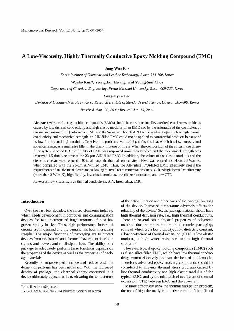
The Mooney equation describes nonlinear behavior of theviscosity increase as the filler loading approaches the maxi-mum packing fraction. It can be expected that the viscosityof the compound will be lower as the maximum packingfraction in the Mooney equation is increased. Figure 1shows the idealized packing of a binary mixture of spheresas a function of composition using their diameter ratios as aparameter.
The thermal conductivity of EMC (65 vol% of fillers) wasgreatly improved up to 5.2 W/m-K by using a binary mixtureof AlN (23 µm and 2µm of Aluminum Nitrides, granuletype) compared to 1.5 W/m-K of crystalline silica filled(65 vol%) EMC which is applied to packaging material as ahigh thermal conductive grade.9 However, the fluidity of thismixture became worse compared to commercial products, i.e., the spiral flow length was only 33 inches compared to over-flow (i. e, more than 60 inches) of commercial products.9
To improve fluidity and minimize the reduction of thermalconductivity of the EMC, fused silica can be considered as asmall size filler because it has low porosity and sphericalshape. In this study, to improve the fluidity of an AlN filledEMC, 2µm fused silica was used as a small size filler in abinary mixture of fillers. Properties such as the spiral flow,thermal conductivity, CTE, flexural strength, elastic modulus,
and dielectric properties of EMC were evaluated as a functionof the volume fraction of small size silica in the binary mix-ture of fillers.
Experimental
Raw Materials.Matrix and Additives: Epoxy resin can be divided into
two types: bisphenol-A and novolac. Solid novolac epoxy ismost widely used as a package material for semi-conductorsbecause of its excellent thermal stability. For this reason, inthis study, novolac epoxy was selected as a base resin, andphenol-novolac as a hardener. Although phenol-cured epoxyis not widely used commercially, it provides excellent mold-ability, electrical properties, and heat and humidity resistancewhen compared with other cured epoxies used in microelec-tronic packaging.11 The average epoxy equivalent weight ofnovolac epoxy is 200 g-mol-1eq, and the average hydroxylequivalent weight of phenol novolac is 106 g-mol-1eq. Acoupling agent, an accelerator, and natural wax were used as
Figure 1. Idealized maximum packing of binary mixtures ofspheres as a function of composition with diameter ratios as aparameter.10
Table I. Physical Properties of Ceramic Fillers and Epoxy Resin
Materials Dielectric Constant Coefficient of Thermal Expansion(10-6/K)
Thermal Conductivity(W/m-K)
Young’s Modulus(GPa)
Fused Silica 3.8 0.5 2 74
AlN 7.0 4.5 150(Practical) 330
Alumina 8.8 5.5 36 385
Epoxy 6~7 50~90 0.2~0.4 2
J.-W. Bae et al.
80 Macromol. Res., Vol. 12, No. 1, 2004
additives. The basic formulation is shown in Table II.7,9
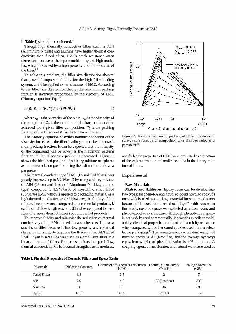
Filler: Even though AlN filler leads to improvements interms of thermal conductivity, thermal expansion andmechanical properties of EMC, it can also cause reductionof the moldability and the flowability. This study tried tosuggest the proper combination of fillers considering fluid-ity, thermal conductivity, thermal expansion, and dielectriccharacteristics of the resulting EMCs. The mean particlesize of an AlN (granule type) filler was 23µm (ART Co.,USA) and that of the fused silica was 2µm (Tokuyama Co.,Japan). The morphology of AlN and fused silica are shownin Figure 2.
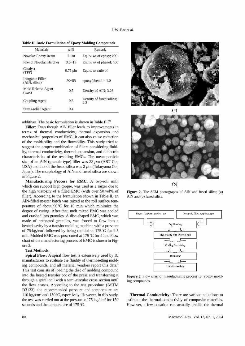
Manufacturing Process for EMC. A two-roll mill,which can support high torque, was used as a mixer due tothe high viscosity of a filled EMC (with over 50 vol% offiller). According to the formulation shown in Table II, anAlN-filled master batch was mixed at the roll surface tem-perature of about 90oC for 10 min which minimize thedegree of curing. After that, melt mixed EMC was cooledand crashed into granules. A disc-shaped EMC, which wasmade of preheated granules, was forced to flow into aheated cavity by a transfer molding machine with a pressureof 75 kgf/cm2 followed by being molded at 175oC for 2.5min. Molded EMC was post-cured at 175oC for 4 hrs. Flowchart of the manufacturing process of EMC is shown in Fig-ure 3.
Test Methods.Spiral Flow: A spiral flow test is extensively used by IC
manufacturers to evaluate the fluidity of thermosetting mold-ing compounds, and all material vendors report this data.3
This test consists of loading the disc of molding compoundinto the heated transfer pot of the press and transferring itthrough a spiral coil with a semi-circular cross section untilthe flow ceases. According to the test procedure (ASTMD3123), the recommended pressure and temperature are110 kgf/cm2 and 150oC, rspectively. However, in this study,the test was carried out at the pressure of 75 kgf/cm2 for 150seconds and the temperature of 175oC.
Thermal Conductivity: There are various equations toestimate the thermal conductivity of composite materials.However, a few equation can actually predict the thermal
Table II. Basic Formulation of Epoxy Molding Compounds
Materials wt% Remark
Novolac Epoxy Resin 7~30 Equiv. wt of epoxy; 200
Phenol Novolac Hardner 3.5~15 Equiv. wt of phenol; 106
Catalyst(TPP) 0.75 phr Equiv. wt ratio of
Inorganic Filler (AIN, silica) 50~85 epoxy/phenol = 1.0
Mold Release Agent (wax) 0.5 Density of AIN; 3.26
Coupling Agent 0.5 Density of fused sillica; 2.2
Stress-relief Agent 0.4
Figure 2. The SEM photographs of AlN and fused silica; (a)AlN and (b) fused silica.
Figure 3. Flow chart of manufacturing process for epoxy mold-ing compounds.
A Low-Viscousity, Highly Thermally Conductive EMC
Macromol. Res., Vol. 12, No. 1, 2004 81
conductivity of composite materials because predictingthermal conductivity of composite materials depends onmany factors. These equations are only useful in roughlyestimating the thermal conductivity of composite materials.That implies thermal conductivity of the composite materialsneed to be experimentally determined.
The measurement of thermal diffusivity (δ) was carried outby a laser flash method (Sinku-Riko Co. Model TC-7000) atroom temperature. The specific heat (C) was measured by aDSC (Perkin-Elmer Co, Pyris I). Also, the density of thespecimen(ρ) was measured by water displacement. Afterthat, the thermal conductivity (k) was calculated by Eq. 212:
(2)
Coefficient of Thermal Expansion: The coefficient ofthermal expansion (CTE) of the composite was measured byusing a bar-shaped specimen in a thermo-mechanical ana-lyzer (Perkin-Elmer, TMA 7e) with a static force (50 mN)and a heating rate of 5oC/min from 40 to 250oC. Eq. 3 wasused to calculate CTE:
(3)
where α is the coefficient of thermal expansion, ∆L/L0 isthe thermal expansion ratio of a sample, and ∆T is the tem-perature difference.
Dielectric Properties: The dielectric property of thecomposite material was measured by using a disk shapedspecimen (φ10Ý 2 mm) with a Dielectric Analyzer (DEA,TA Instrument Co, USA) at room temperature.
Flexural Strength and Modulus: Dynamic mechanicalanalyzer (Perkin-Elmer Co., DMA 7e) was used to measurethe flexural strength and elastic modulus of cured EMC.The sample size was 20Ý 5Ý 3 mm. Stress-strain propertywas measured using a 3-point bending apparatus with a staticforce scan mode (0.1 to 8 N) at room temperature. Also,elastic modulus of cured EMC was measured using a parallelplate apparatus (dynamic force: 100 mN, static force: 110mN) with a heating rate of 5oC/min (80 to 250oC).
Results and Discussion
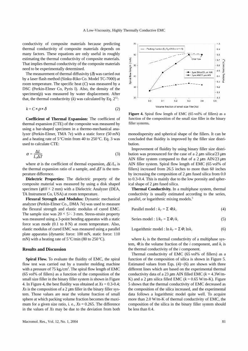
Spiral Flow. To evaluate the fluidity of EMC, the spiralflow test was carried out by a transfer molding machinewith a pressure of 75 kgf/cm2. The spiral flow length of EMC(65 vol% of fillers) as a function of the composition of thesmall size filler in the binary filler system is shown in Figure4. In Figure 4, the best fluidity was obtained at Xs= 0.3-0.4;Xs is the composition of a 2µm filler in the binary filler sys-tem. Those values are near the volume fraction of smallsphere at which packing volume fraction becomes the maxi-mum for a given size ratio, i. e., Xs= 0.265. The differencein the values of Xs may be due to the deviation from both
monodispersity and spherical shape of the fillers. It can beconcluded that fluidity is improved by the filler size distri-bution.
Improvement of fluidity by using binary filler size distri-bution was pronounced for the case of a 2µm silica/23µmAlN filler system compared to that of a 2µm AlN/23 µmAlN filler system. Spiral flow length of EMC (65 vol% offillers) increased from 26.5 inches to more than 60 inchesby increasing the composition of 2µm fused silica from 0.0to 0.3-0.4. This is mainly due to the low porosity and spher-ical shape of 2µm fused silica.
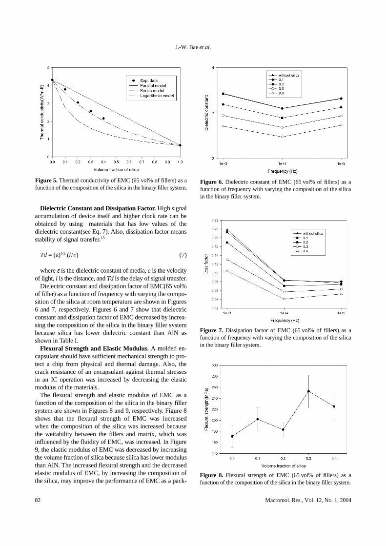
Thermal Conductivity. In a multiphase system, thermalconductivity is usually estimated according to the series,parallel, or logarithmic mixing models.5
Parallel model : kT = Σ Φi ki (4)
Series model : 1/kT = ΣΦ i /ki (5)
Logarithmic model : ln kT = ΣΦi lnki (6)
where kT is the thermal conductivity of a multiphase sys-tem, Φi is the volume fraction of the i component, and ki isthe thermal conductivity of the i component.
Thermal conductivity of EMC (65 vol% of fillers) as afunction of the composition of silica is shown in Figure 5.Estimated values from Eqs. (4)~(6) are shown with threedifferent lines which are based on the experimental thermalconductivity data of a 23µm AlN filled EMC (k = 4.3W/m-K) and a 2µm silica filled EMC (k = 0.65 W/m-K). Figure5 shows that the thermal conductivity of EMC decreased asthe composition of the silica increased, and the experimentaldata follows a logarithmic model quite well. To acquiremore than 2.0 W/m-K of thermal conductivity of EMC, thecomposition of the silica in the binary filler system shouldbe less than 0.4.
k C= ρ× δ×
α L∆L0 T∆------------=
Figure 4. Spiral flow length of EMC (65 vol% of fillers) as afunction of the composition of the small size filler in the binaryfiller systems.
J.-W. Bae et al.
82 Macromol. Res., Vol. 12, No. 1, 2004
Dielectric Constant and Dissipation Factor. High signalaccumulation of device itself and higher clock rate can beobtained by using materials that has low values of thedielectric constant(see Eq. 7). Also, dissipation factor meansstability of signal transfer.13
Td= (ε)1/2 (l /c) (7)
where ε is the dielectric constant of media, c is the velocityof light, l is the distance, and Td is the delay of signal transfer.
Dielectric constant and dissipation factor of EMC(65 vol%of filler) as a function of frequency with varying the compo-sition of the silica at room temperature are shown in Figures6 and 7, respectively. Figures 6 and 7 show that dielectricconstant and dissipation factor of EMC decreased by increa-sing the composition of the silica in the binary filler systembecause silica has lower dielectric constant than AlN asshown in Table I.
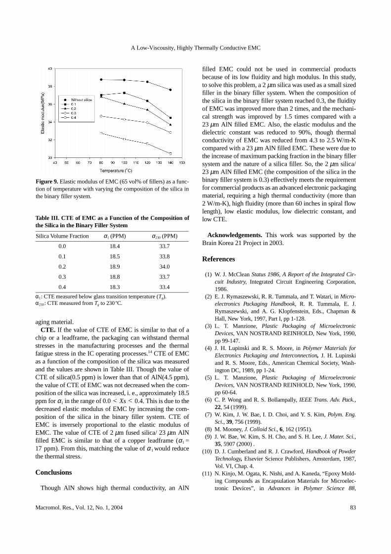
Flexural Strength and Elastic Modulus. A molded en-capsulant should have sufficient mechanical strength to pro-tect a chip from physical and thermal damage. Also, thecrack resistance of an encapsulant against thermal stressesin an IC operation was increased by decreasing the elasticmodulus of the materials.
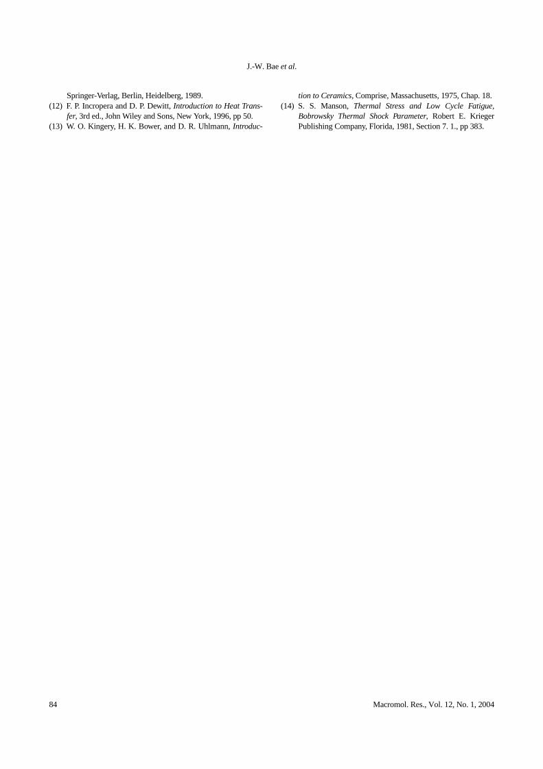
The flexural strength and elastic modulus of EMC as afunction of the composition of the silica in the binary fillersystem are shown in Figures 8 and 9, respectively. Figure 8shows that the flexural strength of EMC was increasedwhen the composition of the silica was increased becausethe wettability between the fillers and matrix, which wasinfluenced by the fluidity of EMC, was increased. In Figure9, the elastic modulus of EMC was decreased by increasingthe volume fraction of silica because silica has lower modulusthan AlN. The increased flexural strength and the decreasedelastic modulus of EMC, by increasing the composition ofthe silica, may improve the performance of EMC as a pack-
Figure 5. Thermal conductivity of EMC (65 vol% of fillers) as afunction of the composition of the silica in the binary filler system.
Figure 6. Dielectric constant of EMC (65 vol% of fillers) as afunction of frequency with varying the composition of the silicain the binary filler system.
Figure 7. Dissipation factor of EMC (65 vol% of fillers) as afunction of frequency with varying the composition of the silicain the binary filler system.
Figure 8. Flexural strength of EMC (65 vol% of fillers) as afunction of the composition of the silica in the binary filler system.
A Low-Viscousity, Highly Thermally Conductive EMC
Macromol. Res., Vol. 12, No. 1, 2004 83
aging material.CTE. If the value of CTE of EMC is similar to that of a
chip or a leadframe, the packaging can withstand thermalstresses in the manufacturing processes and the thermalfatigue stress in the IC operating processes.14 CTE of EMCas a function of the composition of the silica was measuredand the values are shown in Table III. Though the value ofCTE of silica(0.5 ppm) is lower than that of AlN(4.5 ppm),the value of CTE of EMC was not decreased when the com-position of the silica was increased, i. e., approximately 18.5ppm for α1 in the range of 0.0(Xs( 0.4. This is due to thedecreased elastic modulus of EMC by increasing the com-position of the silica in the binary filler system. CTE ofEMC is inversely proportional to the elastic modulus ofEMC. The value of CTE of 2µm fused silica/ 23µm AlNfilled EMC is similar to that of a copper leadframe (α1 =17 ppm). From this, matching the value of α1 would reducethe thermal stress.
Conclusions
Though AlN shows high thermal conductivity, an AlN
filled EMC could not be used in commercial productsbecause of its low fluidity and high modulus. In this study,to solve this problem, a 2µm silica was used as a small sizedfiller in the binary filler system. When the composition ofthe silica in the binary filler system reached 0.3, the fluidityof EMC was improved more than 2 times, and the mechani-cal strength was improved by 1.5 times compared with a23µm AlN filled EMC. Also, the elastic modulus and thedielectric constant was reduced to 90%, though thermalconductivity of EMC was reduced from 4.3 to 2.5 W/m-Kcompared with a 23µm AlN filled EMC. These were due tothe increase of maximum packing fraction in the binary fillersystem and the nature of a silica filler. So, the 2µm silica/23µm AlN filled EMC (the composition of the silica in thebinary filler system is 0.3) effectively meets the requirementfor commercial products as an advanced electronic packagingmaterial, requiring a high thermal conductivity (more than2 W/m-K), high fluidity (more than 60 inches in spiral flowlength), low elastic modulus, low dielectric constant, andlow CTE.
Acknowledgements. This work was supported by theBrain Korea 21 Project in 2003.
References
(1) W. J. McClean Status 1986, A Report of the Integrated Cir-cuit Industry, Integrated Circuit Engineering Corporation,1986.
(2) E. J. Rymaszewski, R. R. Tummala, and T. Watari, in Micro-electronics Packaging Handbook, R. R. Tummala, E. J.Rymaszewski, and A. G. Klopfenstein, Eds., Chapman &Hall, New York, 1997, Part I, pp 1-128.
(3) L. T. Manzione, Plastic Packaging of MicroelectronicDevices, VAN NOSTRAND REINHOLD, New York, 1990,pp 99-147.
(4) J. H. Lupinski and R. S. Moore, in Polymer Materials forElectronics Packaging and Interconnection, J. H. Lupinskiand R. S. Moore, Eds., American Chemical Society, Wash-ington DC, 1989, pp 1-24.
(5) L. T. Manzione, Plastic Packaging of MicroelectronicDevices, VAN NOSTRAND REINHOLD, New York, 1990,pp 60-64.
(6) C. P. Wong and R. S. Bollampally, IEEE Trans. Adv. Pack.,22, 54 (1999).
(7) W. Kim, J. W. Bae, I. D. Choi, and Y. S. Kim, Polym. Eng.Sci., 39, 756 (1999).
(8) M. Mooney, J. Colloid Sci., 6, 162 (1951).(9) J. W. Bae, W. Kim, S. H. Cho, and S. H. Lee, J. Mater. Sci.,
35, 5907 (2000) .(10) D. J. Cumberland and R. J. Crawford, Handbook of Powder
Technology, Elsevier Science Publishers, Amsterdam, 1987,Vol. VI, Chap. 4.
(11) N. Kinjo, M. Ogata, K. Nishi, and A. Kaneda, “Epoxy Mold-ing Compounds as Encapsulation Materials for Microelec-tronic Devices”, in Advances in Polymer Science 88,
Figure 9. Elastic modulus of EMC (65 vol% of fillers) as a func-tion of temperature with varying the composition of the silica inthe binary filler system.
Table III. CTE of EMC as a Function of the Composition ofthe Silica in the Binary Filler System
Silica Volume Fraction α1 (PPM) α230 (PPM)
0.0 18.4 33.7
0.1 18.5 33.8
0.2 18.9 34.0
0.3 18.8 33.7
0.4 18.3 33.4
α1: CTE measured below glass transition temperature (Tg).α230: CTE measured from Tg to 230oC.
J.-W. Bae et al.
84 Macromol. Res., Vol. 12, No. 1, 2004
Springer-Verlag, Berlin, Heidelberg, 1989.(12) F. P. Incropera and D. P. Dewitt, Introduction to Heat Trans-
fer, 3rd ed., John Wiley and Sons, New York, 1996, pp 50. (13) W. O. Kingery, H. K. Bower, and D. R. Uhlmann, Introduc-
tion to Ceramics, Comprise, Massachusetts, 1975, Chap. 18.(14) S. S. Manson, Thermal Stress and Low Cycle Fatigue,
Bobrowsky Thermal Shock Parameter, Robert E. KriegerPublishing Company, Florida, 1981, Section 7. 1., pp 383.